Embed Size (px)
Citation preview

2017 WJTA-IMCA Conference and Expo
October 25-27, 2017 ● New Orleans, Louisiana
Paper
EXPERIMENT ABOUT THE METHOD TO DOUBLE
THE EXTENSION ABILITY OF THE RADIAL JET
DRILLING TECHNOLOGY BY NARROW ANNULUS FLOW
Li Jingbin, Zhang Guangqing, Li Gensheng, Huang Zhongwei, Li Weichang
State Key Laboratory of Petroleum Resources and Prospecting, China U. of
Petroleum Beijing, Beijing 102249, China
ABSTRACT
Radial jet drilling (RJD) technology is an effective method to enhance oil recovery by
penetrating the near-wellbore damage zone, and increasing the drainage radius greatly.
But due to the confinement of the casing size, only the high pressure flexible hose
(HPFH) which is hard to be fed in can be used as the drill stem. Meanwhile, high
steering resistance is applied on the HPFH by the diverter. The extension ability of
RJD is severely limited. In our study, an innovative method to feed in the HPFH by
the high velocity flow in the narrow annulus is proposed. Its feasibility is researched
by theoretical and experimental ways, as well as the effect of different parameters.
Results show that the method is very effective; considerable drag force is generated
easily; the value of the drag force is comparative with the self-propelled force while
the work pressure is less than 1.2 MPa; it is easy to feed in the high pressure flexible
hose by this method; there is a power law relationship between the drag force
generated and the average velocity; the drag force increases linearly with the length of
the narrow annulus, higher average velocity and 1~2mm height are recommended.
According to force analysis, the extension ability of the RJD can be doubled
theoretically by this method.
Organized and Sponsored by WJTA-IMCA

1 INTRODUCTION
Radial jet drilling (RJD) technology is a low-cost, efficient, environmentally friendly method and
particularly suitable for depleted reservoirs, marginal reservoirs, fault block reservoirs, heavy oil
reservoirs, coal bed methane (CBM) reservoirs, etc. (Dickinson et al. 1985, 1989). Over the past 30
years, RJD mainly goes through the original RJD stage and the casing side-tracking RJD stage.
For the complex casing milling and under-reaming process, the original RJD technology is
complicated, destructive and high-risk. Card Landers (1993) presented the casing side-tracking
RJD technology which can complete the turn from the vertical direction to the horizontal direction
within the casing. But for the confinement of the casing size, only the high pressure flexible hose
(HPFH) is used as the drill stem. In addition, high steering resistance force applies on the HPFH
when it gets through the diverter. The extension ability, one of the most critical issues of the casing
side-tracking RJD technology, is limited.
By 1992, over 1,000 horizontal and curved radials have been placed in unconsolidated and
limestone formations in U.S. and Canada with the RJD technology. The average production
improvement is two times to four times (Dickinson 1992). Li (2000) described three key parts of
the traditional RJD technology: big diameter under-reaming technique, design principle of
diverting system, and option of well completion. Buset (2001) believed that the RJD technology is
a safe and cost effective alternative for well production and injection enhancement. The
penetration mechanism and self-induced nozzle pull force were analyzed by theoretical and
experimental methods. Cirigliano (2007) described the first application of RJD technology in deep
wells with complex geometry. It was proven that the RJD technology may be an attractive
substitute for other stimulation techniques, such as fractures, acids, side tracking, etc.
Abdel-Ghany M.A. (2011) highlighted the first application on the casing side-tracking RJD
technology in Egypt. Marbun B. T. H. (2011) reviewed the RJD technology. Cinelli S.D. (2013)
described the recompletion of a portion of a 40 year old field using RJD technology. Li J. etc
(2015) built the self-propelled force model of a multi-orifice nozzle for RJD. Wang B. etc (2016)
discussed the hydraulic calculations of the RJD technology. As shown in his study, the
self-propelled force is about 65N, while the steering resistance force applied to the HPFH by the
diverter is about 36N. More than half of the self-propelled force is expended to overcome the
resistance. Only less than half self-propelled force, 29N exactly, remains for the extension of the
casing side-tracking RJD. It is really important to research this issue.
In this paper, an innovative method to feed in the HPFH by the high velocity flow in the narrow
annulus is presented. A narrow annulus section is designed to form the narrow annulus with the

HPFH. When high velocity fluid flows through it, sizeable drag force is generated in the boundary
layer of the HPFH. The evenly distributed drag force can effectively feed the HPFH and overcome
the resistance of the diverter. The drag force equation is derived and validated by numerical
simulation. To obtain large force, the effects of different parameters are analyzed. The results can
greatly enhance the feed-in ability of the RJD technology.
2 METHOD AND PRINCIPLE
2.1 RJD Process
RJD technology can rehabilitate and optimize oil and gas wells by perforating 30-50mm diameter
lateral holes which are up to 100m radially from the well-bore. The specific RJD process is as
follows: First, a diverter is sent to the desired depth and azimuth by production tubing. Then, the
casing side-tracking assembly including a flexible shaft and a milling bit is sent to the diverter by
the coiled tubing through the production tubing. After that, the jet drilling assembly including the
HPFH and a self-propelled nozzle is sent to the well bottom. The self-propelled nozzle breaks the
rock and drags the assembly moving forward to form a radial hole. During the process, the
production tubing only plays the role of supporting and positioning the diverter. Meanwhile, the
HPFH should maintain straight by a short heavy section to run in hole smoothly.
According to fluid mechanics for engineering technology, when the Reynolds number is relatively
large, the fluid viscosity is usually ignored at macro level. But when it comes to the boundary
layer, because of the high velocity gradient, the viscosity force is considerable. Given that the
HPFH is unable to bear the axial compression force, the idea to feed-in the HPFH by the drag
force generated by the high velocity fluid in the narrow annulus is formulated.
2.2 Principle
As shown in Fig. 1, the key equipment of this method is the narrow annulus section. The HPFH
passes through the center of the narrow annulus section and forms the narrow annulus whose
height ranges from 1mm to 2mm. A limit joint is used to keep the narrow annulus section with the
HPFH. The lower section of the narrow annulus section is designed to seal the diverter to form the
only flow channel bewteen the annulus of production tube and HPFH.
During the running in hole process, the narrow annulus section can mean the HPFH straight
instead of the short heavy section. When the radial jet drilling begins, high pressure fluid is
pumped through the annulus of the production tubing and coiled tubing-flexible hose assembly,

then arrive the diverter, and flow through the narrow annulus, enter into the annulus of casing and
production tube, at last return to the ground. For the small size of the narrow annulus, high
velocity flow and the high velocity gradient are formed in the boundary layer. Consequently, large
axial drag force is applied on the out wall of the HPFH. Evenly distributed drag force could
overcome the diversion resistance generated by the diverter, and feed the HPFH into stratum.
Based on the force analysis, theoretically, the extension ability of the RJD technology would be
doubled. Meanwhile, the structure of the self-propelled jet bit can be optimized to make sure that
it efficiently breaks the rock. In addition, due to the large flow area of the diverter guideway, the
outflow of the narrow gap cannot influence the debris carrying from the radial hole. This method
can greatly facilitate the development of the RJD technology with the sample and reliable tools.
3 DRAG FORCE EQUATION
3.1 Fundamental Assumptions
To simplify the model, the following assumptions are made:
1) The working fluid is incompressible Newtonian fluid.
2) The velocity of the fluid in narrow annulus is equal to the average velocity.
3) The flow is steady.
4) The narrow annulus is concentric.
3.2 Derivation
The rheological properties of fluid are important to the annular flow. Water, a Newtonian fluid, is
designed to be used here. The flow of Newtonian fluids through annulus has drawn considerable
attention in the past. To apply the well-known relationship between pipe flow and annular flow,
various effective diameter definitions are presented. By replacing the diameter term, the Fanning
friction factor and Reynolds number equation can be used in annular flow. According to Reed’s
(1993) study, the Fanning friction factor for a concentric annulus should be based on the Hydraulic
Diameter, Dhy, which is simply the difference between the inner and outer diameters. The
Reynolds number should be based on an equivalent diameter equal to square of Lamb’s Diameter,
DL2, divided by Dhy (see Eq.3). Jones and Leung (1981) proved that these definitions also apply to
fully-turbulent flow through an annulus.
Hydraulic diameter of the annulus flow can be expressed as
2 1hyD D D (1)
Where, D1 is the inner diameter of the annulus, m; D2 is the outer diameter of the annulus, m.

The “Applied Drilling Engineering” book (1986) gives the Lamb’s diameter which is
1 2
2 2 2 2 2 2
2 1 2 1 2 1/ ln /LD D D D D D D
(2)
According to Reed (1993), equivalent diameter equals
2 /eq L hyD D D (3)
Reynolds number based on the equivalent diameter can be calculated by
Re /eqD e equ D (4)
Where, ue is the average velocity of the flow, m/s; μ is the viscosity, mPa*s; ρ is the density,
kg/m3.
To obtain enough drag force, the velocity in the narrow annulus should be no less than 10m/s. The
HPFH used in our laboratory has a 14.2mm outer diameter, while the inner diameter of the
annulus section is about 18.0mm. When the room temperature is 20℃, density of water is
998.203kg/m3, and its viscosity is 1.005 mPa*s. Then, the Reynolds number based on hydraulic
diameter, Lamb’s diameter, and equivalent diameter can be obtained respectively
Re 37743hyD , Re 162493
LD , Re 699547eqD (5)
According to Reed (1993), Hanks (1980), Hanks and Peterson (1982), the critical Reynolds
number based on Lamb’s diameter for the transition of laminar and turbulent is about 2100. The
flow in the narrow annulus here can be taken as turbulent boundary layer flow. The drag force can
be calculated by the equation of the incompressible turbulent boundary layer.
According to Churchill’s study (1995), the local shear stress applied on the inner wall of a
concentric annulus can be obtained by
2 2
0 11
12w
R R dp
R dz
(6)
Where, R0 is the radius at which the total shear stress is zero, m; R1 is the radius of the inner wall,
m.
The R0 expression at Re≈105 is derived and validated by Rehme(1974) with his own
experimental data, gives
0.386
0 1 1
2 0 2
R R R
R R R
(7)
Where, R2 is the radius of the outer wall, m.

For a narrow annulus, the drag force acting on the inner wall can be calculated by
2 2
1 1 0 10
2L
D wF R dz R R P (8)
Where, ΔP is the pressure drop of the narrow annulus, Pa; L is the length of narrow annulus, m.
According to Fanning equation, the pressure loss can be obtained by
2
2
e
hy
uLP f
D
(9)
Where, f is the Fanning friction factor, dimensionless; L is the length of the narrow annulus, m;
Dhy is the hydraulic diameter, for the annulus flow, it equals 2(R2-R1), m.
Jonsson and Sparrow (1965) investigated the flow field and the pressure drop and friction factor
characteristics for turbulent flow in eccentric annular ducts. The friction factor expression of the
concentric annular flow can be obtained by
0.180.153RehyDf (10)
By substituting Eq.9, and Eq. 10 into Eq.8, it gives
2 2 2
0 1
0.180.240
Re
e
D
hy
L u R RF
D
(11)
Where,FD is the drag force generated by the narrow annulus, N; ρ is the fluid density, water is
used here, and its density is about 998.203 kg/m3 at 20℃.
3.3 Case Study
If a narrow annulus section is set as 1m length, 0.018m inner dimeter. When there is a HPFH with
0.0142m outer dimeter gets through the section, a 2.0 mm height narrow annulus is built.
According to Eq.11, if the average velocity is 20m/s, the drag force can be obtained by
2 2 2 -6
0.18
1 998.203 20 7.952 -7 *100.240* =45.759N
0.0038 79458.95DF
(12)
In this case, the drag force is about 45.759N. The same HPFH is used in Wang bin’s study (2016),
the steering resistance is measured as 36.85N with 35 MPa inner pressure by experiment. It is can
be inferred that the drag force generated by the high velocity flow in narrow annulus can
overcome the steering resistance, even can feed the HPFH into the oil and gas reservoir. Given
that the ejector force is only about 65N, theoretically, the extension ability of RJD technology
even can be doubled.

4 EXPERIMENT SET UP
A series of experiments are conducted to study the feasibility of the narrow annulus. To better
understand the method, effects of the structure parameters are analyzed.
4.1 Experiment Principle
The experiment principle to measure the drag force generated by high velocity flow in the narrow
annulus is shown in Fig.2. A designed measurement joint and different length seamless tube make
the main experiment body. There are fluid inlet, pressure measure point, and motive seal on the
measurement joint. The HPFH passes through the center of measurent joint and seamless tube
forms the narrow annulus. A digital display tension meter is connected with the HPFH by iron
wire to measure the force. Due to the variable high-pressure induced by the plunger pump, the
measured force changes continuously; thus, the peak value is recorded. The high pressure fluid
flow in the narrow annulus through the fluid inlet and form high velocity flow in the narrow
annulus. Considerable drag force is applied on the HPFH and measured by the tension meter. At
the same time, the pressure data in the annulus is collected and stored by a data acquisition
system.
The force condition of the HPFH is analyzed. Along the flow direction, drag force applies on the
HPFH, labeled as Fdrag. To drag the HPFH to move, the friction force between the HPFH and the
seamless tube, and that of the motive seal section is needed to be overcome, labeled as Ffriction.
The difference of the drag force and friction force is measure by the tension meter, labeled as
Fmeasure. According to that, the drag force can be obtained
Fdrag=Fmeasure+ Ffriction (13)
Where, Fdrag is the drag force generated by the narrow annulus, N; Fmeasure is the measured force
which obtained by the tension meter, N;Ffriction is the friction force which can be got by using the
tension meter to drag the HPFH through the experiment body, N.
4.2 Apparatus
A high-pressure plunger pump is used as the power source with a rated pressure of 60 MPa and a
certified capacity of 200 L/min. A hydro-pressure sensor with a measuring range of 30 MPa, an
output current of 4~20 mA, and an accuracy of 0.1% F*S is used to record the pressure. A digital
display tension meter with 500N range and 0.1N precision is used to measure the force. A data
acquisition system with a National Instruments multi-channel data acquisition card installed is
used to collect and store the pressure data. Given the HPFH used in field, the Exitflex 703-8 blue

hose with 17.5mm outer diameter is adopted here. Seamless tubes with 1m/0.5m length and 22mm
inner diameter are used.
4.3 Project
To validate and better understand the performance of the method to generate the drag force, a
series of experiments are designed and carried out. The experiment project is shown in table 1.
5 RESULTS AND DISCUSSION
5.1 Validation
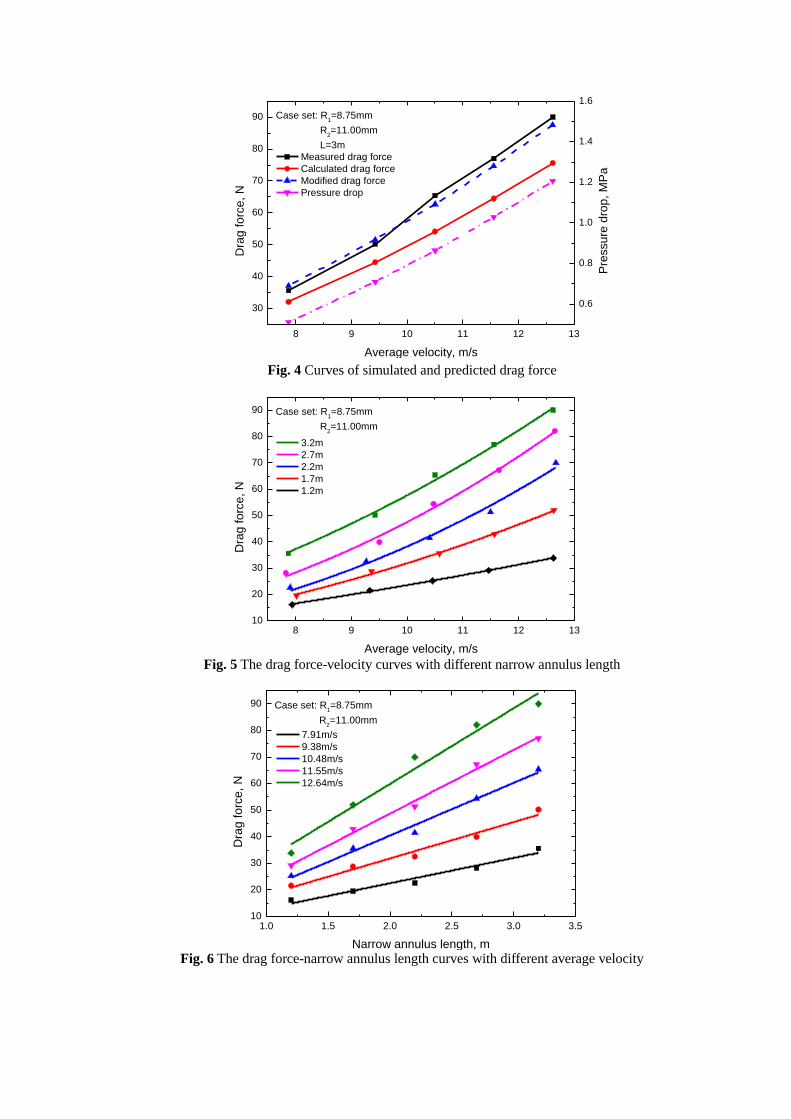
By experiment, we acquire a series of drag forces and pressure drops. Substituting structure
parameters and flow parameters into Eq.11, a series of drag forces are obtained. As shown in Fig.4,
the abscissa is the average velocity in the narrow annulus, and the ordinate is the drag force. The
measured drag force and the calculated drag force by Eq.11 are shown in solid line, and agrees
with each other very well. But the measured drag force is a little bigger than the calculated force.
All that may be caused by that the peak drag force is used and the HPFH is not straight and
concentric with the seamless tube. A 1.16 times relationship is found between the real drag force
and the calculated force. To predict the drag force accurately, Eq.11 can be modified as
2 2 2
0 1
0.180.278
Re
e
D
hy
L u R RF
D
(14)
As shown in Fig.4, the drag force calculated by modified model is displayed in dash line and
almost coincides with the real drag force. All these indicate that the modified model can be used to
calculate the drag force accurately. Besides, even though the average velocity is about 12.62m/s,
the real drag force is up to 90N which is much bigger than the steering resistance, even the
self-propelled force which is about 65N according to Wang (2016). At the same time, the biggest
pressure drop is about 1.2MPa which is very easy to implement. Once again, it is can be inferred
that the method is competitive and practical.
5.2 Effect of the Average Velocity
When the height of the narrow annulus is fixed, higher average velocity means more fierce flow
and greater velocity gradient which may lead to bigger drag force. The effect of the average
velocity is analyzed. The drag force-velocity curves with different lengths are shown in Fig.5. The
power law relationship is adopted to fit the data. The fitting results are good. It means that the high
velocity, the higher drag force while the augment is increasing. As shown in Fig.5, when the
length is 1.7m, the largest drag force is up to 52N, which is much bigger than the steering

resistance (about 36N) while the biggest velocity is only about 12.64m/s. It is proved that the drag
force generated by the narrow annulus can overcome the resistance and even feed the HPFH into
the strata, and it is easy to implement. According to the average velocity-pressure drop
relationship, higher velocity is easy to implement, and larger drag force can be achieved.
5.3 Effect of the Narrow Annulus Length
The narrow annulus length determines the exposure time of the high velocity flow and the HPFH.
To better design the narrow annulus length, effect of the narrow annulus length is researched. As is
shown in Fig. 6, the drag force applied on the HPFH linearly increases with the narrow annulus
length. With bigger average velocity the slope of the curve is larger which means the bigger
increcment per unit length. Even the narrow annulus length is only 1.2m, the drag force can
achieve 33.87N with 12.64m/s average velocity which is easy to implement. Given that the narrow
annulus section occupies the length of the HPFH which will increase the inner frictional resistance
of the fluid in the HPFH, we recommend that the narrow annulus length should range from 1 to
1.5 m.
6 CONCLUSION
The method to feed the HPFH by the drag force generated by the high velocity flow in the narrow
annulus is presented for the RJD technology. Its feasibility is researched by theoretical and
experimental ways, as well as the effect of different parameters. The following conclusions are
achieved:
1. The method is proved that it can generate enough drag force to overcome the steering
resistance and even feed in the HPFH to the oil and gas reservoir. According to stress analysis, the
extension ability of the RJD technology can be doubled theoretically.
2. Based on the boundary-layer theory of a concentric annulus, the drag force equation is
formulated. The equation is modified by experiment data. The modified equation can calculate the
drag force accurately.
3. There is a power law relationship between the drag force generated and the average
velocity. The drag force linearly increases with the length of the narrow annulus. The recommend
length ranges from 1 to 1.5 meters. For the complicated situation, higher drag force should be
generated by larger average velocity.

7 ACKNOWLEDGMENTS
This study was funded by the National Natural Science Foundation of China(No. 51521063 and
No. U1562212). This support is gratefully acknowledged by the authors, who are also grateful to
the reviewers of this paper for their detailed comments.
8 REFERENCES
Abdel-Ghany, M.A., Siso, S., Hassan, A.M., Pierpaolo, P., Roberto, C. 2011. New Technology
Application, Radial Drilling Petrobel, First Well In Egypt. Presented at the Offshore
Mediterranean Conference, Ravenna, Italy, 23-25 March. OMC-2011-163.
Bourgoyne, A. T. Jr., Chenevert, M. R, Millheim, K. K., and Young, F. S. Jr., Applied Drilling
Engineering, Society of Petroleum Engineers, Richardson, TX, p. 140, 1986.
Buset, P., Riiber, M. and Eek, A. 2001. Jet Drilling Tool: Cost-Effective Lateral Drilling
Technology for Enhanced Oil Recovery. Presented at the SPE/ICoTA Coiled Tubing
Roundtable, Houston, Texas,7-8 March. SPE-68504-MS.
Carl, W. L.1993. Method of and apparatus for horizontal well drilling. US Patent No. 5,853,056.
Cirigliano, R.A. and Blacutt, J.F.T. 2007. First Experience in the Application of Radial Perforation
Technology in Deep Wells. Presented at the Latin American & Caribbean Petroleum
Engineering Conference, Buenos Aires, Argentina, 15-18 April. SPE-107182-MS.
Churchill, S. W., & Chan, C. 1995. Turbulent flow in channels in terms of turbulent shear and
normal stresses. AIChE Journal, 41(12): 2513-2521.
Cinelli, S. D., & Kamel, A. H. 2013. Novel Technique to Drill Horizontal Laterals Revitalizes
Aging Field. SPE/IADC Drilling Conference, Amsterdam, The Netherlands, 5-7 March.
doi:10.2118/163405-MS.
Dickinson, W. and Dickinson, R.W. 1985. Horizontal Radial Drilling System. Presented at the
SPE California Regional Meeting, Bakersfield, California, 27-29 March. SPE-13949-MS
Dickinson, W., Anderson, R.R. and Dickinson, R.W. 1989. The Ultrashort-Radius Radial System.
SPE Drilling Engineering 4(03): 247-254. SPE-14804-PA.
Dickinson, W., Dykstra, H., Nees, J.M., Dickinson, E. 1992. The Ultrashort Radius Radial System
Applied to Thermal Recovery of Heavy Oil. Presented at the SPE Western Regional Meeting,
Bakersfield, California, 30 March-1 April. SPE-24087-MS.
Jonsson V K, Sparrow E M. 1966. Experiments on turbulent-flow phenomena in eccentric annular
ducts[J]. Journal of Fluid Mechanics, 25(1):65-86.
Jones, O. C. Jr., and Leung, J. C. M.1981. An Improvement in the Calculation of Turbulent
Friction in Smooth Concentric Annuli. ASME Jour. Fluids Engineering, 103, 615-23.
Hanks, R W. 1980. Critical Reynolds Numbers, for Newtonian Flow in Concentric Annuli, AlChE
J. No.1, 152-4.
Hanks, R. W., and Peterson, J. M. 1982. Complex Transitional Flows in Concentric Annuli, AlChE
J. 28, No.5, 800-06.
Li, Y., Wang, C., Shi, L., Guo, W. 2000. Application and Development of Drilling and Completion
of the Ultrashort-radius Radial Well by High Pressure Jet Flow Techniques. Presented at the
International Oil and Gas Conference and Exhibition in China, Beijing, China, 7-10 November.
SPE-64756-MS.

Li, J., Li, G., Huang, Z., Song, X., Yang, R., Peng, K. 2015. The Self-Propelled Force Model of a
Multi-Orifice Nozzle for Radial Jet Drilling. Journal of Natural Gas Science and Engineering,
24(2015), P441-448. doi: 10.1016/j.jngse.2015.04.009.
Marbun, B. T. H., Zulkhifly, S., Arliyando, L., & Putra, S. K. 2011. Review of Ultrashort-Radius
Radial System (URRS). International Petroleum Technology Conference, Bangkok, Thailand ,
15-17 November. doi:10.2523/IPTC-14823-MS.
Reed, T. D., & Pilehvari, A. A. 1993. A New Model for Laminar, Transitional, and Turbulent Flow
of Drilling Muds. SPE Production Operations Symposium, 21-23 March, Oklahoma City,
Oklahoma. doi:10.2118/25456-MS.
Wang, B., Li, G., Huang, Z., Li, J., Zheng, D., & Li, H. 2016. Hydraulics Calculations and Field
Application of Radial Jet Drilling. SPE Drilling & Completion 31(01): 71 - 81.
doi:10.2118/179729-PA.
9 NOMENCLATURE
ue The main velocity, m/s
R0 The radius at which the total shear stress is zero, m
R1 The radius of the inner wall, m
R2 The radius of the outer wall, m
D1 The inner diameter of the annulus, m
D2 The outer diameter of the annulus, m
Dhy The hydraulic diameter of annular flow, m
DL The Lamb’s diameter of annular flow, m
Deq The equivalent diameter of annular flow, m
ReDhy The Reynolds number based on the hydraulic diameter, dimensionless
ReDL The Reynolds number based on the Lamb’s diameter, dimensionless
ReDeq The Reynolds number based on the equivalent diameter, dimensionless
f The Fanning friction factor, dimensionless
L The length of the narrow annulus, m
τw1 The local shear stress applied on the inner wall of a concentric annulus, Pa
FD The drag force acting on the inner wall, N
10 TABLES
Table 1 Parameter settings for experiment
No.
Outer diameter
of the HPFH
mm
Inner diameter of
the seamless tube
mm
Narrow gap
length
m
Average velocity
m/s
1 17.50 22.00 1.20 7.91/ 9.38/ 10.48/
11.55/12.64
2 17.50 22.00 1.70 7.91/ 9.38/ 10.48/
11.55/12.64
3 17.50 22.00 2.20 7.91/ 9.38/ 10.48/
11.55/12.64
4 17.50 22.00 2.70 7.91/ 9.38/ 10.48/
11.55/12.64
5 17.50 22.00 3.20 7.91/ 9.38/ 10.48/
11.55/12.64

11 GRAPHICS
Oil tubing
Narrow annulus
section
Diverter
HPFH
Self-propelled
nozzle
Length
Fluid
Narrow
annulus
Height
Limit joint
Limit joint
Fig. 1 Schematic diagram of the method to feed in the HPFH by narrow annulus
High pressure flexible hose
Fluid inlet
Pressure sensor
Tension meter
Fmeasure
FdragFfriction
Seamless tube
Narrow annulus
Joint
Measurement joint
Fig.2 Principle diagram of drag force measurement experiment
Fig.3 Photo of drag force measurement experiment
8 9 10 11 12 13
30
40
50
60
70
80
90
Average velocity, m/s
Dra
g fo
rce
, N
Case set: R1=8.75mm
R2=11.00mm
L=3m
Measured drag force
Calculated drag force
Modified drag force
Pressure drop
0.6
0.8
1.0
1.2
1.4
1.6
Pre
ssu
re d
rop
, M
Pa
Fig. 4 Curves of simulated and predicted drag force
8 9 10 11 12 1310
20
30
40
50
60
70
80
90
Average velocity, m/s
Dra
g fo
rce
, N
Case set: R1=8.75mm
R2=11.00mm
3.2m
2.7m
2.2m
1.7m
1.2m
Fig. 5 The drag force-velocity curves with different narrow annulus length
1.0 1.5 2.0 2.5 3.0 3.510
20
30
40
50
60
70
80
90
Dra
g fo
rce
, N
Case set: R1=8.75mm
R2=11.00mm
Narrow annulus length, m
7.91m/s
9.38m/s
10.48m/s
11.55m/s
12.64m/s
Fig. 6 The drag force-narrow annulus length curves with different average velocity