Embed Size (px)
Citation preview
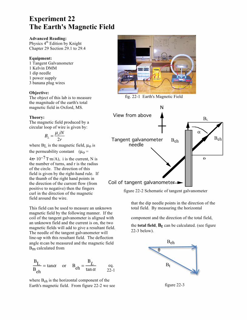
Experiment 22 The Earth's Magnetic Field Advanced Reading: Physics 4th Edition by Knight Chapter 29 Section 29.1 to 29.4 Equipment: 1 Tangent Galvanometer 1 Kelvin DMM 1 dip needle 1 power supply 3 banana plug wires Objective: The object of this lab is to measure the magnitude of the earth's total magnetic field in Oxford, MS. Theory: The magnetic field produced by a circular loop of wire is given by:
BL =
µoiN2r
where BL is the magnetic field, µo is the permeability constant (µo =
4π. 10−7 Τ.m/A), i is the current, N is the number of turns, and r is the radius of the circle. The direction of this field is given by the right-hand rule. If the thumb of the right hand points in the direction of the current flow (from positive to negative) then the fingers curl in the direction of the magnetic field around the wire. This field can be used to measure an unknown magnetic field by the following manner. If the coil of the tangent galvanometer is aligned with an unknown field and the current is on, the two magnetic fields will add to give a resultant field. The needle of the tangent galvanometer will line-up with this resultant field. The deflection angle α can be measured and the magnetic field Bm calculated from
eq. 22-1
where Beh is the horizontal component of the Earth's magnetic field. From figure 22-2 we see
that the dip needle points in the direction of the total field. By measuring the horizontal component and the direction of the total field,
the total field, Bt can be calculated. (see figure 22-3 below).
figure 22-3
Be
Bm
α
Tangent galvanometer needle
View from aboveN
Coil of tangent galvanometer
figure 22-2 Schematic of tangent galvanometer
fig. 22-1 Earth's Magnetic Field
BLBeh
= tanα or Beh =ΒL
tanα
BL
Beh Beh Beh
Beh
Beh
θ
Bt
Beh
Procedure: 1. Wire the tangent galvanometer, the current limiting resistor, the Kelvin DMM , and the power supply together in a series circuit. (see fig. 22-1) The tangent galvanometer has three places to connect wires. Where the wires are connected determines how many loops the current must pass through. Wire the circuit so that the current passes through 5 loops. Have your lab instructor approve your circuit before plugging in the power supply. 2. Align the tangent galvanometer coil so that it is parallel to the to the earth's magnetic field. (as shown in figure 22-2) Do this by rotating the dip needle so that it is horizontal and can act as a compass. The coil of the tangent galvanometer should be in line with the "compass" needle which points north-south. 3. Measure three different values for α by varying the current input. The values for α will be more accurate if they fall between 20 degrees and 60 degrees 4. Repeat step three using 10 loops and again for 15 loops of current carrying wire, for a total of nine trials. Calculate the average horizontal field from these data. 5. Measure the dip angle of the total field with the dip needle. Make sure that the power supply to the tangent galvanometer is off. From this angle, calculate the total field. Questions/Conclusions: 1. Compare (i.e., calculate % difference of ) the value of the total field found in this experiment to the magnetic field found in the website given in question # 2 below. 2. Magnetic declination is defined by Answers.com as “At a particular location, the horizontal angle between true meridian (true north-south line) and magnetic meridian (direction of compass needle).” What is the magnetic declination of your hometown, New York City and Los Angeles, CA? Please include where you are from.
Questions (continued) You can to go to this website for magnetic declination http://www.magnetic-declination.com/ 3. Look at figure 22-2 (Schematic of tangent galvanometer) above. It is a schematic of a galvanometer like the one used in the lab being observed from the top. Assume the end of the arrow is the north end of a compass needle. a) Using the right hand rule, what is the direction of the current (you can define current as either positive or negative) which causes the needle to deflect the direction that it does in the figure. See section 29.2 of text. b) Using the Biot-Savart Law show that you get the same current direction. See Example 29.2 from section 29.3. Your diagrams should have both the loop and a figure similar to the one in Example 29.2. You are also reminded that since the phenomena being described is 3-dimensional, your diagrams of loop can be either a top view or a side view or both. 4. Calculate the total resistance of 20 loops of copper wire on the galvanometer if the wire is 1 mm in diameter and the loops are 20 cm in diameter. (The resistivity of copper ρ = 1.69 x 10⁻⁸ Ω .m) 5. In this experiment and the Current Balance experiment you connected had your DMM (in ammeter mode) plugged into the 20A setting. Based upon what you observed in the Part 2 (The Resistance of an Ammeter) from the Series & Parallel Circuits experiment, explain what you think the resistance of the ammeter might be (i.e., resistance of DMM in ammeter setting). There is single numerical answer.
Beh


![Experiment 2 6. Magnetic Field Induced by Electric Fieldphyslab.snu.ac.kr/documents/manual/En/2-6.pdf · Experiment 2-6. Magnetic Field Induced by Electric Field ... Magnetic Field]](https://img.dokumen.tips/doc/110x75/5ea11c78b8c7202f935229c4/experiment-2-6-magnetic-field-induced-by-electric-experiment-2-6-magnetic-field.jpg)