Embed Size (px)
Citation preview

EXPERIENCE OF THE NATIONAL AVIATION UNIVERSITY
IN APPLICATIONS OF ACTIVE NOISE CONTROL IN AN AIRCRAFT CABIN
Tokarev V.I., Makarenko V.N., Zaporozhets O.I. 23‐26 September, 2014, Vilnius, Lithuania
“Aircraft Noise Reduction by Flow Control and Active / Adaptive Techniques”

Active Noise Control (ANC)
The concept of ANC was first described in a patent by P. Lueg N 655508. ANC basic idea: the electro-acoustic generation of a sound field to cancel an unwanted existing sound fieldThe basic elements: sensors, control algorithm, actuators.Over last 40 years the huge amount of literature was published on ANC systems. The number of publication on ANC systems is doubling every 5 years.

2 types of Active Noise Control
Feedforward and feedback control are the two main methods that have been used for ANC systems.
A feedforward controller requires a measure of the incoming disturbance to generate the required control signal for the control source.
A feedback controller requires no knowledge of the incoming disturbance and acts to change the system response by changing the system resonance frequencies and damping.

Specific features of the application of ANC system in aircraft cabins
1. Small crew cabin volume.2. Small time of reverberation and noise transmission loss of the fuselage in the low frequency range.3. Aircraft cabin noise from external sources (propellers, engines) is determined by performances of near acoustical field.
4. Low frequency noise less than Schroder frequency ( ): 5. The non-stationary acoustic field inside the crew cabin: the noise from aircraft engines, airframe noise, the noise from air conditioning systems (ACS), and the structure–born noise.
31.5 63 125 250 500 1k 2k 4k
30
40
f, Hz
R, d
B
63 125 250 500 1k 2k 4k 8k0.15
0.2
0.25
0.3
f, Hz
T 60, s
Tu-154An-24IL-86

Typical noise spectrum of turboprop aircraft Antonov 24 in the crew cabin
Sound radiation from propeller
Typical sources for aircraft interior noise
Noise from air conditioning systems (ACS)
Noise spectra from ACS in the crewcabin of turbojet aircraft Antonov-72

Typical measured noise spectrum of aircraft noise
Noise spectra from ACS in the crew cabin of turbojet aircraft Tupolev-154M for different phases of flight:
run and takeoff approach and landing

Typical calculated noise spectrum of aircraft noise
The noise spectra inside the cabins of turbojet aircraft Tupolev-154M in cruise flight at H=11000 m, M=0.85

Typical calculated noise spectrum of aircraft noise
Airframe noise
-90
-80
-70
-60
-50
-40
-30
-20
-10
0
50 80 125
200
315
500
800
1250
2000
3150
5000
8000
1/3 octave frequency bands, HzSP
L, d
B
Sum Jet Fan Turbine Combastor Airframe

Active noise control in the crew cabin of
aircraft Antonov-24The model of polyharmonic acoustic fields control in the crew cabin of aircraft Antonov-24. Mathematical model of ANC was defined in the frequency domain in the form of a vector equation:
where - n-dimensional vectors of Fourier coefficients of the input and output signals; - matrix of the frequency characteristics of the active reduction of noise; - n-dimensional vector of Fourier coefficients of signals characterizing the noise in cabin. Full compensation of oscillations in the control points is defined as a vector
Iterative algorithm was proposed for solving the equation to ensure cancellation of polyharmonic acoustic fields, which is implemented in the system with feedback control.

Principles of decreasing polyharmonic acoustic pressure in the crew cabin of aircraft Antonov-24
Two groups of loudspeakers were used to reduce noise in the cabin of aircraftAntonov-24. One group of loudspeakers simulates radiation of propellers, another,which is located inside the cabin, is used to compensate the sound field in the cabinof aircraft Antonov-24. Active reduction of interior noise in the cabin of aircraftAntonov-24 was carried out at three points at the head of the pilot. The tableshows the results of studies on the compensation of the fundamental blade passfrequency and second harmonics of the propeller in the three control points.
Synphasing Implementation feedback control and
synphasingDecreasing of sound pressure
level, dB
1 2 3 1 2 32 4.7 5.6 3.5 5 10.4

Active noise control in open ductOne method of the air conditioning system noise reduction in the cabin is the use of compensating loudspeakers in air distribution nozzles.
The feed-forward control system in the infinite duct includes: reference microphone, the electronic controller, loudspeaker, and error microphone
In contrast, for the simplest example of active control of a plane wave in the infinite ductnear open duct sound field is represented by two acoustic waves – the direct and reflectedwaves.In the National Aviation University performed theoretical and experimental studies of theeffectiveness of active noise reduction methods of air conditioning systems. Experimental studies
were carried out in an anechoic chamber using an open duct with diameter 0.1 m.

ANC application for open ductDirectional characteristics of sound radiation from an open duct, the frequency of
100 Hz (below cut-off frequency)An error microphones are adjusted for next angles: 1 - 00, 2 - 900, 3 - 1350
1, 2, 3 are loudspeakers;4 is sound source (loudspeaker);5 is soundproofing.

ANC application for open duct
Effect of the error microphone placement in open duct with active noise control system (loudspeaker N 2).
1.Without active noise control usage 2.The error microphone inside duct atat distance 8 cm from the end of the duct3.The error microphone outside duct atdistance 20 cm from the duct end4.The error microphone outside duct at distance 70 cm from the duct end

Application of active noise control system in open duct
Directional characteristics of sound radiation from an open duct for the frequencies of 250 Hz and 500 Hz (curve 1 - without active noise control usage)
2 - frequency 250 Hz 2 - frequency 500 Hz(loudspeaker N 2). (loudspeaker N 2).

Sound transmission control through the cylindrical panel
Property ValueYoungs modulus in longitudinal direction, EL
15.7∙109 Pa
Youngs modulus in transversal direction, ET
6.3∙109 Pa
Shear modulus, GLT 2.1∙109 PaPoisson’s ratio ν12 0.204
Damping loss factors
ηL 1.005∙10‐2ηT 1.699∙10‐2ηLT 1.807∙10‐2
Density 1430 kg/m3
Dimensions L×h×b 0.560×3∙10‐3×0.860 m3
Radius, a 2m
Property ValueYoungs modulus 6.85∙1010 PaPoisson’s ratio 0.3Density 2770 kg/m3
Dimensions 2.2×1.67×1,2∙10‐3 m3
Radius 2 m
40 50 60 70 80 90 100 110 120-5
0
5
10
15
20
25
30
35
TL, d
B
f, Hz

Sound transmission control through curved aircraft panel with stringers and ring frames
Differential equations of vibration of the curved panel with stringers, frames and masses (the form of Donnell-Mushtari-Vlasov equations):
Basic equations of bending and torsional displacements ws , of stringers, frames wr, and mass displacements wk , written as:
, ,

Sound transmission control through curved aircraft panel with distributed point masses
The optimization task is formulated to design such control parameters, whichmaximize transmission loss of the panel. The objective criteria is an integralassessment of sound insulation in the frequency range fmin , fmax :
under constrains imposed on location and weight of masses, d is transmissioncoefficient.The logarithmic form of transmission coefficient is the transmission loss (TL) :TL= -10lg d. The control parameters are: .The genetic algorithm with penalty functions for the constraints has been used tosolve this task. Theoretical and experimental investigation showed TL increase ofthe panel (aircraft Antonov-72) at the frequency of 374 Hz to 6.9 dB. The panel ismade of duraluminium with dimensions 2.22m x1.6m, thickness is 1.2 mm, mass is 23.6kg.
0.5 1 1.50.4
0.6
0.8
1
1.2
1.620kg1.510kg
x, m
y, m
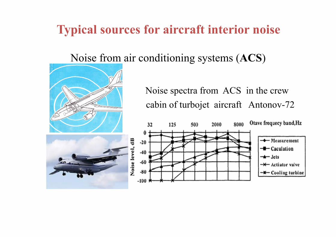
Sound transmission control through curved aircraft panel
The effect of a number of distributed masseson TL increase in case of optimal location ofthe masses on investigated panel (total weightof distributed point masses is equal to 13.3%of the total panel mass).
0 0.05 0.1 0.15 0.2 0.25 0.3 0.350
5
10
15
20
TL
, dB
Added mass in parts of panel
240 Hz240+360 Hz
1 2 30
5
10
15
TL
, dB
Quantity of additional masses
240Hz240+360Hz360Hz
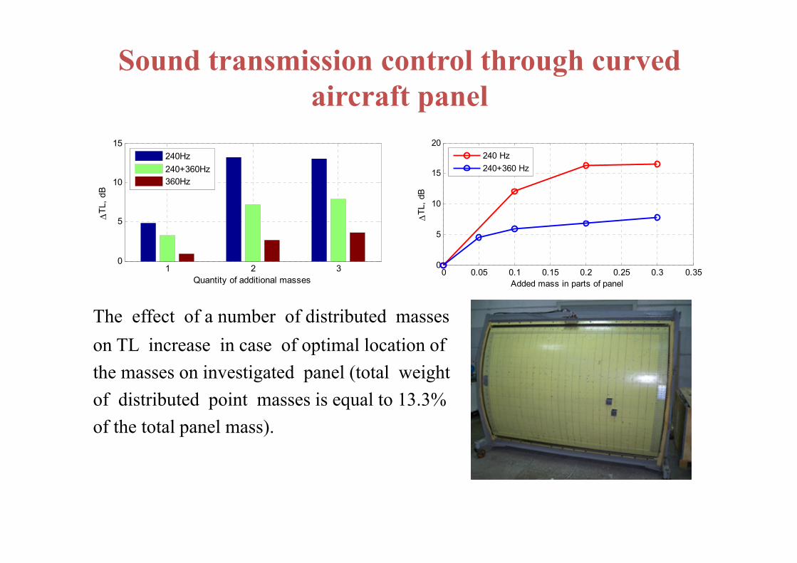
Application of sound insulation designs and damping layers for increasing fuselage TL
Principle of impedance mismatch is used in optimal sound insulation designs. It provides a soundinsulation of a multilayered structure due to two effects: the absorption of sound energy in thematerial and the reflection of sound waves from the interface between materials.Sound energy absorption is small in solid materials, so the sound insulation of such materials isdetermined by effect of sound reflection.On the other hand, effect of reflected sound is relatively small for porous materials comparing tothe irreversible loss of sound energy in the material layer, so soundproofing is completelydetermined by absorption in this case.In real structures both effects determine the actual sound insulation of the panels.
05
1015202530
250
400
630
1000
1600
2500
4000
6300
1000
0
f, Hz
R, d
B
0,3
0,4
0,5
0,6
0,7
0,8
0,9
1
160
200
250
315
400
500
630
800
1000
1250
1600
2000
Frequency, Hz
BWT-120
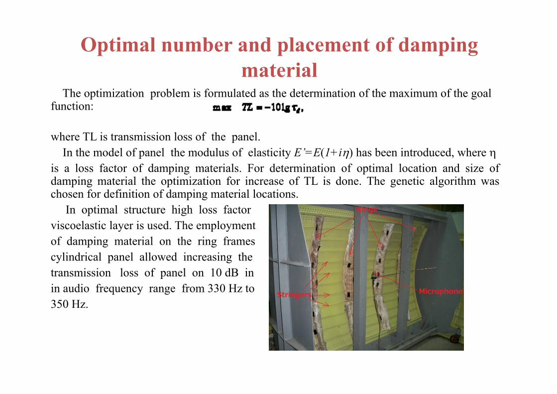
Optimal number and placement of damping material
The optimization problem is formulated as the determination of the maximum of the goal function:
where TL is transmission loss of the panel.In the model of panel the modulus of elasticity E’=E(1+i) has been introduced, where
is a loss factor of damping materials. For determination of optimal location and size ofdamping material the optimization for increase of TL is done. The genetic algorithm waschosen for definition of damping material locations.
In optimal structure high loss factorviscoelastic layer is used. The employmentof damping material on the ring framescylindrical panel allowed increasing thetransmission loss of panel on 10 dB inin audio frequency range from 330 Hz to350 Hz.
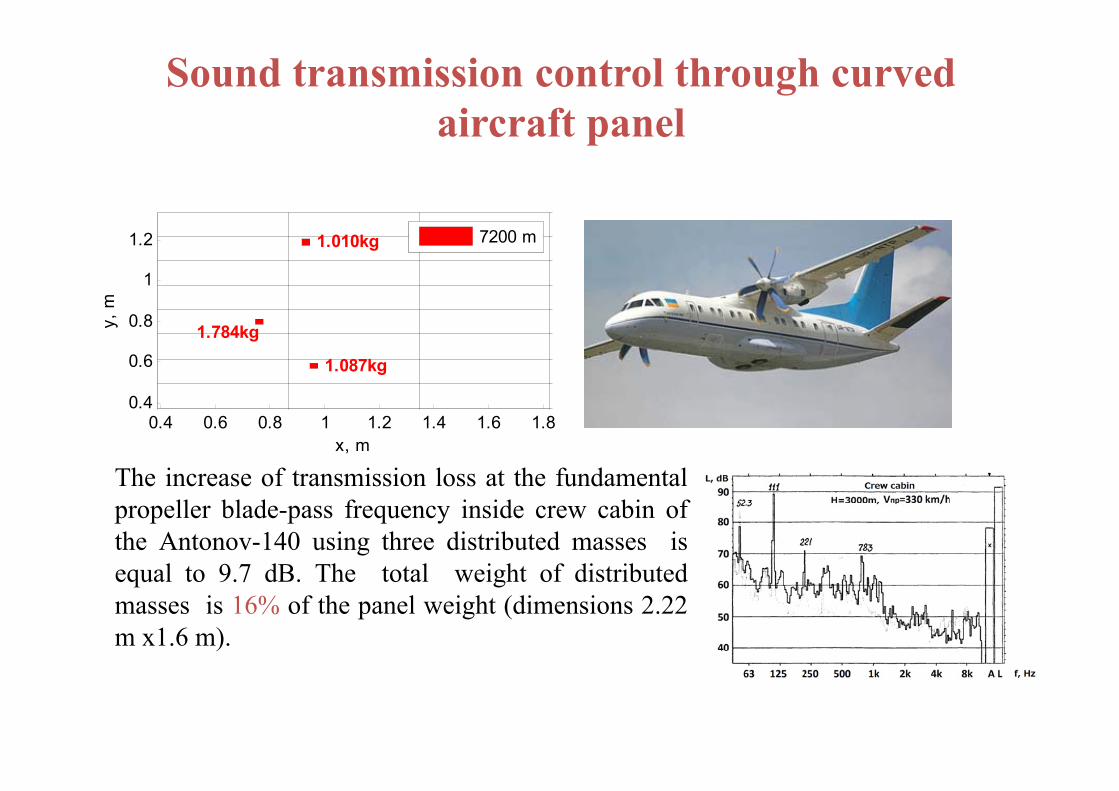
Sound transmission control through curved aircraft panel
The increase of transmission loss at the fundamentalpropeller blade-pass frequency inside crew cabin ofthe Antonov-140 using three distributed masses isequal to 9.7 dB. The total weight of distributedmasses is 16% of the panel weight (dimensions 2.22m x1.6 m).
0.4 0.6 0.8 1 1.2 1.4 1.6 1.80.4
0.6
0.8
1
1.2
x, m
y, m
1.087kg
1.784kg
1.010kg
7200 m

Future developments1. Aircraft noise reductions in cabins due to active noise control are achievable as a result of the interaction between system theory, engineering acoustics, electro-acoustics and adaptive signal processing. Examples of the development and installation of ANC system:- the reference and error sensors are used to obtain and derive a signal that is used by the controller to generate the driving signal for the control of loudspeakers;
From C. H. Hansen, DOES ACTIVE NOISE CONTROL HAVE A FUTURE?, Manuscript Number: 1226U
‐ novel actuator systems suited specifically to active control applications. An example is a low cost inertial actuator and/or the flat loudspeaker developed by Ultra Electronics to fit behind aircraft trim panels;
The piezoelectric actuators on jet engine fan blades

Future developments
2. The next generation of ANC systems will be powerful to allow very large numbers of channels as well as a high enough processing speed to implement feedback as well as feedforward control.Block diagram of multichannel ANC system MIMO (multiple-input and multiple-output system).
From T. Kletschkowski, Adaptive Feed-Forward Control of Low Frequency Interior Noise, Springer, 2012.

Future developmentsThe airframe noise generated by the air flow over the fuselage can be reduced using feedback active control (from Gibbs, G.P. and Cabell, R.H. , 2002. Active Control of Turbulent Boundary Layer Induced Sound Radiation from Multiple Aircraft Panels. Paper no. AIAA 2002-2496, 8th AIAA/CEAS Aeroacoustics Conference, Breckenridge, CO, June 16-18, 2002.)
Multiple single-channel independent feedback controllers can be used to improve the low-frequency transmission loss of a panel (from Gardonio, P., Bianchi, E. and Elliott, S.J. 2002. Smart panel with multiple decentralized units for the control of sound transmission. Part I: Theoretical predictions, Part II: Design of the decentralized control units, Part III: Control system implementation. Proceedings of Active 2002, Southampton, UK, July 15-17.)

Future developments3. Application of predictive control using active foam
Predictive control techniques can be used to provide regulation of plate vibrations over a wide bandwidth using piezoelectric actuators. The active element consists of regular foam with piezoelectric polymer polyvinylidene fluoride embedded in it and shaped similar to a sine wave. The foam is able to act as a passive absorber because the air molecules oscillate at the same frequency as the disturbance. This oscillation causes frictional losses. A control actuator adaptively modifies the acoustic impedance of the vibrating surface. The goal of the active foam is to modify the acoustic radiation impedance seen by the structure in order to yield a net decrease in the far-field sound power radiated by the vibrating surface.
From K. W. Eure, Adaptive PredictiveFeedback Techniques for VibrationControl, 1998.
Future developments
- implementation of active structural acoustic control (for structure-borne sounds) includes simultaneously active control of structural vibrations and active control of sound fields;
-semi-active approaches with application of passive and active noise control;
- smart panel design.