Embed Size (px)
Citation preview

EXPERIENCE IN INTRODUCTION OF
ELECTRICAL LOGGING THROUGH METALLIC
BORING CASING

TASKS TO BE SOLVED
Experience of technology introduction has shown the possibility for solution of the following tasks:
• - determination of current hydrocarbon saturation index;• - evaluation of reservoirs saturation nature;• - evaluation of influx composition from the facility (ratio
product/water);• - studying of fluid contacts advance;• - detection of inactive intervals;• - shale barriers integrity control between the process facilities; • - studying of brine and pumped water advance with different level
of salinity;• - borehole geophysical researches complex addition when
controlling technical condition of boreholes; • - researches in cased bottomholes in case of expected problems
during drilling;• - detection and evaluation of productive facilities missed during
exploring.
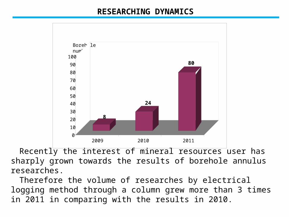
RESEARCHING DYNAMICS
Borehole number
8
24
80
0
10
20
30
40
50
60
70
80
90
100
2009 2010 2011
Recently the interest of mineral resources user has sharply grown towards the results of borehole annulus researches.
Therefore the volume of researches by electrical logging method through a column grew more than 3 times in 2011 in comparing with the results in 2010.
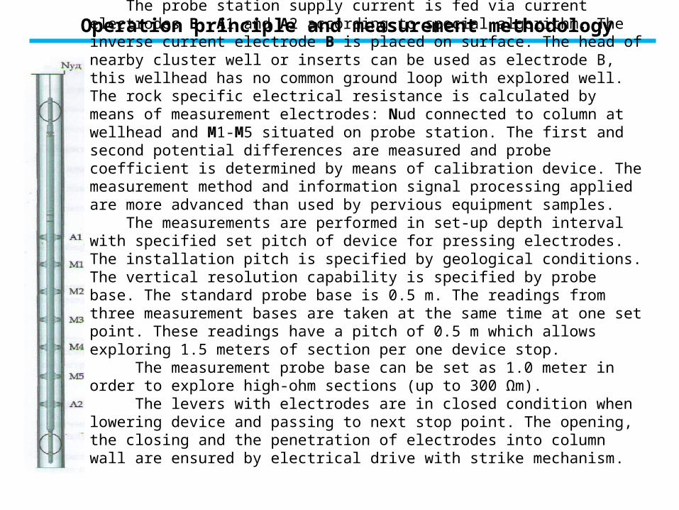
Operation principle and measurement methodology
The probe station supply current is fed via current electrodes B, A1 and A2 according to special algorithm. The inverse current electrode B is placed on surface. The head of nearby cluster well or inserts can be used as electrode B, this wellhead has no common ground loop with explored well. The rock specific electrical resistance is calculated by means of measurement electrodes: Nud connected to column at wellhead and M1-M5 situated on probe station. The first and second potential differences are measured and probe coefficient is determined by means of calibration device. The measurement method and information signal processing applied are more advanced than used by pervious equipment samples. The measurements are performed in set-up depth interval with specified set pitch of device for pressing electrodes. The installation pitch is specified by geological conditions. The vertical resolution capability is specified by probe base. The standard probe base is 0.5 m. The readings from three measurement bases are taken at the same time at one set point. These readings have a pitch of 0.5 m which allows exploring 1.5 meters of section per one device stop. The measurement probe base can be set as 1.0 meter in order to explore high-ohm sections (up to 300 Ωm). The levers with electrodes are in closed condition when lowering device and passing to next stop point. The opening, the closing and the penetration of electrodes into column wall are ensured by electrical drive with strike mechanism.
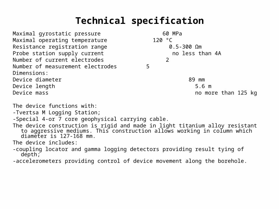
Technical specificationMaximal gyrostatic pressure 60 MPaMaximal operating temperature 120 °CResistance registration range 0.5-300 ΩmProbe station supply current no less than 4ANumber of current electrodes 2Number of measurement electrodes 5Dimensions:Device diameter 89 mmDevice length 5.6 mDevice mass no more than 125 kg
The device functions with:-Tvertsa M Logging Station;-Special 4-or 7 core geophysical carrying cable.The device construction is rigid and made in light titanium alloy resistant to aggressive mediums.
This construction allows working in column which diameter is 127-168 mm.The device includes:-coupling locator and gamma logging detectors providing result tying of depth;-accelerometers providing control of device movement along the borehole.

INTERPRETATION AND CONCLUSIONS ISSUE PECULIARITIES
First stage is an evaluation of reliability of resistance values received when recording and a linkage between pointwise record and depth. Reliability is estimated by beds which electrical resistance does not change with time (water saturated reservoirs and impermeable intervals). Linkage with section is done by means of rocks natural gamma radiation measuring module and collar locator built in the device.
Second stage is an explanation of current water salinity that saturates the rock. Knowledge of water resistance is required for estimation of current hydrocarbon saturation index. Operational experience shows that when efficient interpreting, the Analyst, as a rule, has no information concerning actual salinity of pumped and brine water mixture. This information will be available after testing. There are several explanations of water salinity (electrical resistance): - Average salinity of associated waters by deposit;- Use of associated waters analyses by neighbor boreholes;- Determination of current salinity (chlorine content) in certain borehole by additional methods of borehole geophysical researches.

INTERPRETATION AND CONCLUSIONS ISSUE PECULIARITIES
Third stage of interpretation is an estimation of current hydrocarbon saturation index and influx composition forecasting.
This stage is implemented when being available trustworthy information concerning petrophysical dependences of water saturation factor on resistance (Archie Formula) and oil and water relative permeability coefficients for process facility under research.
Current oil saturation index, researched bed saturation nature and expected value of water quantity in influx are given in operational conclusion. The conclusion is supplemented with geological and geophysical tablet.
INTERPRETATION EXAMPLES UNDER VARIOUS GEOLOGICAL CONDITIONS.

Validity of resistance measured behind the column 1.Thick water saturated bed. Initial resistance was estimated as 3.8 Ohm. Current resistance has not almost changed and is equal to 3.5 Ohm. 2. Resistance remains without changes in the interval of tight-rocks bedding. Saline brine water encroachment of bed 3. Gas saturated bed resistance has reduced from 28 Ohm to 12 Ohm.Current gas saturation index is 70%. Initially gas saturation index was equal to 80%. The bed is encroached by brine water. Oil-Water Contact Raise 4. Oil-water contact is traced clear in initially oil saturated bed at depth of 2357.9 by resistance decrease from 20 Ohm to 6 Ohm. It has raised more than by 2 m.
INTERPRETATION EXAMPLES UNDER VARIOUS GEOLOGICAL SITUATIONS

Beds unaffected by operation process 1.Top clay-bearing beds with low reservoir properties are unaffected by operation process.Current resistance has not changed against the resistance in open bore. Current resistance has been raised sharply from the depth of 1761.2 from 5 to 8 Ohm. It definitely indicates fresh water encroachment.
Barrier damage 2. Barrier bedded directly under encroached bed is damaged.
Fresh water encroachment of oil saturated beds. 3. Oil beds are encroached up to residual-oil saturation. Influx composition forecasted by resistance measure in column and actual influx are coincided. Fluid influx is gotten with 95% of water.
INTERPRETATION EXAMPLES UNDER VARIOUS GEOLOGICAL SITUATIONS

Brine water encroachment of beds 1.Beds have been encroached. Resistance has reduced from 6 Ohm to 3 Ohm.
Thin interlayers unaffected by operation process2. Underlying thin isolated interlayers are unaffectedby operation process.
Brine water encroachment of oil saturated bed 3. Brine water encroachment appeared clear in oil saturated bed that caused reducing of resistance from 11 Ohm to 6 Ohm. Forecasted water influx is 16% and actual water influx is 5%.
INTERPRETATION EXAMPLES UNDER VARIOUS GEOLOGICAL SITUATIONS
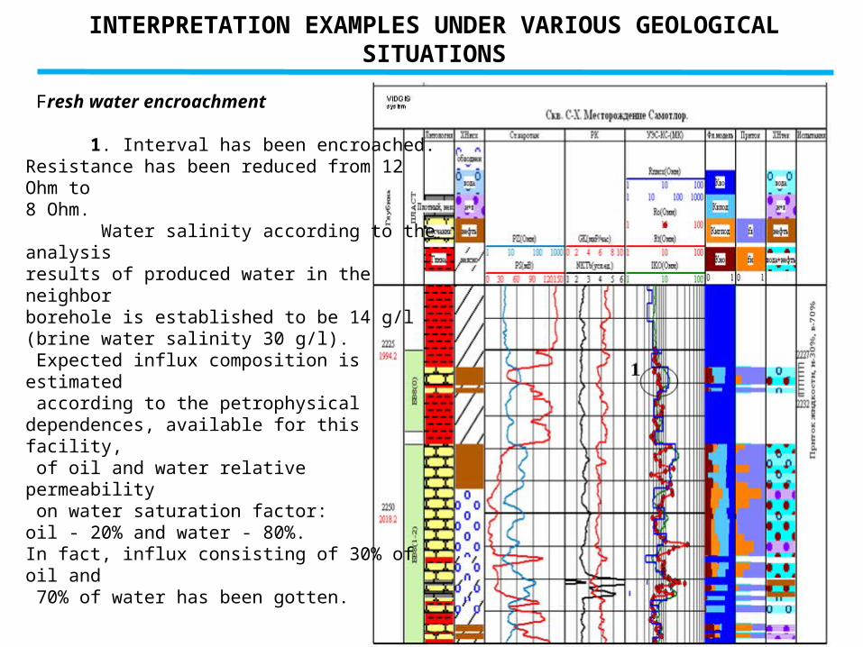
Fresh water encroachment 1. Interval has been encroached.Resistance has been reduced from 12 Ohm to 8 Ohm. Water salinity according to the analysis results of produced water in the neighbor borehole is established to be 14 g/l (brine water salinity 30 g/l). Expected influx composition is estimated according to the petrophysical dependences, available for this facility, of oil and water relative permeability on water saturation factor: oil - 20% and water - 80%. In fact, influx consisting of 30% of oil and 70% of water has been gotten.
INTERPRETATION EXAMPLES UNDER VARIOUS GEOLOGICAL SITUATIONS

Fresh water encroachment of gas deposit. Gas saturated beds unaffected by process facilities. 1. Gas deposit has been unevenly encroached by fresh water. Thin beds with worsened reservoir properties are unaffected by operation process.
Fresh water encroachment of oil pool. 2. Initially oil saturated interval has been encroached by fresh water. Forecasted water influx is estimated to be 37% and actual water influx is 30%.
Possible formation of technogenic deposit. 3. Maybe the technogenic deposit has been formed in initially water saturated part of section. Resistance has increased from 4 Ohm to 30 Ohm. Current resistance has decreased again up to the water saturated bed resistance - 4 Ohm in underlying interval 863- 1864.8.
INTERPRETATION EXAMPLES UNDER VARIOUS GEOLOGICAL SITUATIONS

INTERPRETATION EXAMPLES UNDER VARIOUS GEOLOGICAL SITUATIONS
Barrier damage between process facilities 1. Barrier has been damaged between process facilities. Current resistance of argillaceous-clay materials considerably has increased.
Fresh water encroachment of gas saturated beds 2. Gas saturated bed has been encroached by fresh water. Water salinity has been established according to the analysis of produced water in neighbor boreholes. Hydrocarbon saturation index has reduced from 55% to 48%. Forecasted water influx is 29% according to current hydrocarbon saturation index and actual water influx is 36%.

THANK YOU FOR ATTENTION!