Embed Size (px)
Citation preview

4 952.500.6200 | www.exlar.com
GS Series Linear Actuators with Integrated Motor
Exlar GS Series Linear Actuator FamilyThe GS Series linear actuator family offers you two grades of actuator to provide cost effective options in order to meet your application’s requirements. View the chart below to compare the GSX and GSM models.
All GS Series actuators use a specially designed roller screw mechanism for converting electric motor power into linear motion within the actuator. Planetary rollers assembled around the actuator’s extending rod follow threads which are precisely machined on the inside surface of the actuator’s hollow armature. Linear motion is produced in precise synchronization with the armature rotation. Because this roller screw mechanism has an inherently larger cumulative contact surface, these actuators have a much longer working life, and can handle heavier loads at higher speeds than is possible from a similarly sized unit built around a ball screw system.
Exlar’s T-LAM™ segmented lamination stator technology delivers higher continuous motor torque than is available in traditionally wound motors. T-LAM technology consists of stator segments, each containing individual phase wiring for maximum motor performance. The improved efficiencies of the GSX Series are a result of the limited heat generation qualities inherent in the segmented stator design as seen above. The elimination of end turns in the stator, and use of thermally conductive potting removes the parts most susceptible to failure in a traditional stator. Other design advantages include:
• Neodymium-iron-boron magnets provide high flux density and maximum motor torque.
• Thermally conductive potting of the entire stator provides increased heat dissipation and provides protection from contamination in oil-cooled units.
• Each stator segment contains individual phase wiring. External winding of individual segments provides maximum slot fill for maximum motor performance.
• Motors with T-LAM technology have Class 180 H insulation systems compliant with UL requirements.
• UL recognized component.
• Motors with T-LAM technology are CE compliant
The Actuator & Motor, All in one Compact UnitWith other actuator technologies, customers are usually responsible for engineering the completed linear motion system. This usually includes purchasing the motor, gear reducer, timing belt, mounting hardware, flexible couplings, etc. separately. Then they all must be assembled to perform properly in a given application.
GS Series actuators eliminate all this systems engineering. These units are single, fully integrated component packages – much smaller than traditional rotary-to-linear conversion mechanisms.
Designed for Closed Loop Servo SystemsTheir brushless servo design means GS Series units can be used in advanced closed-loop servo systems when velocity and positioning is required. Position feedback can be delivered in a number of different forms. These include resolvers, encoders or internally mounted linear position feedback sensors.
GSX and GSM Differences GSX (pg 5) GSM (pg 42)
Roller Screw Option High Capacity Standard Capacity
Ingress Protection IP65S IP54S (IP65S optional)
No. of Stacks 1, 2, 3 1, 2
Life BSY (Ball Screw Years) 15X 2 to 5X
Oil Cooling Yes No
Food Grade Paint Yes Yes
Electroless Nickel Housing Yes Yes
Stainless Steel Case Yes No
Hard Coat Anodized Yes Yes
LVDT FB Yes (except 2" frame) Yes (except 2" frame)
5.5 in. Frame Yes No
7 in. Frame Yes No
Force (lbf) 92 - 15,000 92 - 3,966
1.0 Lead 50 & 60 only No
Rear Brake all all
Speeds (ips) 5 - 40 5 - 37.5
Electroless Nickel Connectors Yes Yes
Backlash (in) 0.004 0.008
Lamination Endcaps
Individual Segments
Courtesy of Steven Engineering, Inc. - (800) 258-9200 - [email protected] - www.stevenengineering.com

952.500.6200 | www.exlar.com 5
GSX Series Linear Actuators with Integrated Motor
GSX Series–High Capacity Roller Screw OptionFor applications that require long life and continuous duty, even in harsh environments the GSX Series actuator offers a robust solution. The life of the GSX Series can exceed that of a ball screw actuator by 15X while delivering high speeds and high forces. This compact package has all the advantages that our GS Series offers.
Sealed for Long Life with Minimum MaintenanceGSX Series actuators have strong advantages whenever outside contaminants are an issue. In most rotary-to-linear devices, critical mechanisms are exposed to the environment. Thus, they must be frequently inspected, cleaned and lubricated.
In contrast, the converting components in all Exlar GSX units are mounted within the sealed motor housing. With a simple bushing and seal arrangement on the smooth extending rod, abrasive particles or other contaminants are prevented from reaching the actuator’s critical mechanisms. This assures trouble-free operation even in the most harsh environments.
Lubrication requirements are minimal. GSX actuators can be lubricated with either grease or recirculated oil. Grease lubricated units will run up to 10,000 hours without regreasing. Recirculated oil systems eliminate this type of maintenance altogether. A GSX Series actuator with a properly operating recirculating oil system will operate indefinitely without any other lubrication requirements.
Available in Five Frame Sizes
2" GSX20 3" GSX30 4" GSX40 5" GSX50 7" GSX60
If you need a custom design, your local sales representative will work with you to engineer a solution specifically tailored to your application.
Feature Standard Optional
External anti-rotate mechanism
No Yes
Internal Anti-rotate No Yes
Pre-loaded follower No Yes
Electric brake No Yes
External End switches No Yes
ConnectorsMS or Threaded Circular
Style Connectors
Electroless Nickel Connectors/Male NPT with Potted Leads/
Manufacturers Connectors
Mounting StyleExtended Tie Rods, Side Tapped Mounting Holes, Trunnion, Rear
Clevis, Front or Rear FlangeCustom Mountings
Rod EndMale or Female:
U.S. Standard or MetricSpecials Available To Meet
OEM Requirements
Lubrication
Greased, Oil Connection Ports are Built-in for Customer
Supplied Recirculated Oil Lubrication
Specials Available To Meet OEM Requirements
Primary FeedbackStandard Encoders or
Resolvers to Meet Most Amplifier Requirements
Custom Feedback
Absolute Linear Feedback
No ICT, including signal conditioner
GSX
Ser
ies
Courtesy of Steven Engineering, Inc. - (800) 258-9200 - [email protected] - www.stevenengineering.com

6 952.500.6200 | www.exlar.com
Repeatable force control plus positioning accuracy extends the life of costly tools when Exlar linear actuators are used in precision clamping applications.
Hydraulic cylinder replacementBall screw replacementPneumatic cylinder replacementChip and wafer handlingAutomated flexible fixturingDispensersMachine toolAutomated assemblyParts clampingAutomatic tool changersVolumetric pumps
Medical equipmentConveyor diverters / gatesPlastics equipmentCut-offsDie cuttersPackaging machineryEntertainmentSawmill equipmentOpen / close doorsFillersFormersPrecision grindersIndexing stages
LiftsProduct sortingMaterial cuttingMaterial handlingRiveting / fastening / joiningMoldingSemiconductorPick and place systemsRobot manipulator armsSimulatorsPrecision valve controlVentilation control systems
PressingProcess controlTube bendingWeldingStampingTest standsTension controlWeb guidanceWire windingFood Processing
Exlar GSX Series Linear Actuators Applications Include:
In clean room applications like those common to semiconductor manufacturing, the compact design of our GSX Series saves critical space.
Because they cycle quickly and can be synchronized to line speeds, Exlar actuators produce dramatic improvements in web control applications.
Repeatable force, reliable positioning accuracy, and flexible control make GSX actuators a perfect fit for assembly presses or test stands.
GSX Series Linear Actuators with Integrated Motor
Courtesy of Steven Engineering, Inc. - (800) 258-9200 - [email protected] - www.stevenengineering.com

952.500.6200 | www.exlar.com 7
These charts represent typical linear speed versus linear force curves for the GSX actuators using common brushless motor amplifiers. The GSX Series are compatible with many different brushless motor amplifiers, and differences in the
performance ratings of these amplifiers can alter the actuator’s performance. Thus, the curves below should be used for estimation only. (Further information is available by contacting your local sales representative.)
GSX20-.2 Inch Lead
1 Stack2 Stack3 Stack
1 Stack2 Stack3 Stack
GSX20-.4 Inch Lead
700 (3114)
600 (2670)
500 (2224)
400 (1779)
300 (1334)
200 (890)
100 (445)
0
450 (2002)
400 (1779)
350 (1557)
300 (1334)
250 (1112)
200 (890)
150 (667)
100 (445)
50 (222)
0
200 (890)
150 (667)
100 (445)
50 (222)
0
Speed in/sec (mm/sec)
Speed in/sec (mm/sec)
Speed in/sec (mm/sec)
Speed in/sec (mm/sec)
Speed in/sec (mm/sec)
Speed in/sec (mm/sec)
Forc
e lb
f (N
m)
Forc
e lb
f (N
m)
Forc
e lb
f (N
m)
Forc
e lb
f (N
m)
Forc
e lb
f (N
m)
Forc
e lb
f (N
m)
GSX20-.1 Inch Lead
GSX20-.2 Inch Lead
GSX20-.4 Inch Lead
GSX30-.1 Inch Lead
GSX30-.2 Inch Lead
GSX30-.5 Inch Lead
1 Stack2 Stack
GSX30-.1 Inch Lead
GSX30-.2 Inch Lead
1 Stack2 Stack3 Stack
GSX30-.5 Inch Lead
1 Stack2 Stack3 Stack
0 1 2 3 4 5 6 7 8 9 (25.4) (50.8) (76.2) (101.6) (127) (152.4) (177.8) (203.2) (228.6)
0 2 4 6 8 10 12 14 16 18 (50.8) (101.6) (152.4) (203.2) (254) (304.8) (355.6) (406.4) (457.2)
0 5 10 15 20 25 30 35 (127) (254) (381) (508) (635) (762) (889)
GSX Series Speed vs. Force Curves
0 1 2 3 4 5 6 (25.4) (50.8) (76.2) (101.6) (127) (152.4)
0 2 4 6 8 10 12 (50.8) (101.6) (152.4) (203.2) (254) (304.8)
0 5 10 15 20 25 30 (127) (254) (381) (508) (635) (762)
1400 (6228)
1200 (5338)
1000 (4448)
800 (3559)
600 (2670)
400 (1779)
200 (890)
0
1000 (4448)
800 (3559)
600 (2670)
400 (1779)
200 (890)
0
450 (2002)
400 (1779)
350 (1557)
300 (1334)
250 (1112)
200 (890)
150 (667)
100 (445)
50 (222)
0
Test data derived using NEMA recommended aluminum heatsink 10" x 10" x 1/4" for GSX20 and 10" x 10" x 3/8" for GSX30
GSX Series Linear Actuators with Integrated Motor
See page 28 for explanation of motor stator options (1x8, 2x8, 3x8)
1 Stack2 Stack
GSM20-.1 Inch Lead
GSX
Ser
ies
Courtesy of Steven Engineering, Inc. - (800) 258-9200 - [email protected] - www.stevenengineering.com

8 952.500.6200 | www.exlar.com
GSX Series Speed vs. Force CurvesGSX40-.1Inch Lead
1 Stack2 Stack
4000 (17793)
3500 (15569)
3000 (13345)
2500 (11121)
2000 (8896)
1500 (6672)
1000 (4448)
500 (2224)
0
Speed in/sec (mm/sec)
Forc
e lb
f (N
m)
GSX40-.1 Inch Lead
0 1 2 3 4 5 6 (25.4) (50.8) (76.2) (101.6) (127) (152.4)
GSX40-.2 Inch Lead
1 Stack2 Stack3 Stack
Speed in/sec (mm/sec)
Forc
e lb
f (N
m)
GSX40-.2 Inch Lead
0 2 4 6 8 10 12 (50.8) (101.6) (152.4) (203.2) (254) (304.8)
3000 (13345)
2500 (11120)
2000 (8896)
1500 (6672)
1000 (4448)
500 (2224)
0
GSX40-.5 Inch Lead
1 Stack2 Stack3 Stack
1400 (6228)
1200 (5338)
1000 (4448)
800 (3559)
600 (2670)
400 (1779)
200 (890)
0
Speed in/sec (mm/sec)
Forc
e lb
f (N
)
GSX40-.5 Inch Lead
0 5 10 15 20 25 30 (127) (254) (381) (508) (635) (762)
GSX40-.75 Inch Lead
1 Stack2 Stack3 Stack
900 (4003)
800 (3559)
700 (3114)
600 (2670)
500 (2224)
400 (1779)
300 (1334)
200 (890)
100 (445)
0
Speed in/sec (mm/sec)
Forc
e lb
f (N
m)
GSX40-.75 Inch Lead
0 5 10 15 20 25 30 35 40 (127) (254) (381) (508) (635) (762) (889) (1016)
Speed in/sec (mm/sec)
Forc
e lb
f (N
m)
GSX50-.1 Inch LeadGSX50-.1 Inch Lead
1 Stack2 Stack
0 1 2 3 4 5 (25.4) (50.8) (76.2) (101.6) (127)
8000 (35586)
7000 (31138)
6000 (26689)
5000 (22241)
4000 (17793)
3000 (13345)
2000 (8896)
1000 (4448)
0
Speed in/sec (mm/sec)
Forc
e lb
f (N
m)
GSX50-.2 Inch LeadGSX50-.2 Inch Lead
1 Stack2 Stack3 Stack
0 2 4 6 8 10 (50.8) (101.6) (152.4) (203.2) (254)
6000 (26689)
5000 (22241)
4000 (17793)
3000 (13345)
2000 (8896)
1000 (4448)
0
Speed in/sec (mm/sec)
Forc
e lb
f (N
m)
GSX50-.5 Inch LeadGSX50-.5 Inch Lead
1 Stack2 Stack3 Stack
0 5 10 15 20 25 (127) (254) (381) (508) (635)
3000 (13345)
2500 (11121)
2000 (8896)
1500 (6672)
1000 (4448)
500 (2224)
0
Speed in/sec (mm/sec)
Forc
e lb
f (N
m)
GSX50-1.0 Inch LeadGSX50-.1.0 Inch Lead
1 Stack2 Stack3 Stack
0 10 20 30 40 50 (254) (508) (762) (1016) (1270)
1600 (7117)
1400 (6228)
1200 (5338)
1000 (4448)
800 (3559)
600 (2670)
400 (1779)
200 (890)
0
Test data derived using NEMA recommended aluminum heatsink 12" x 12" x 1/2" for GSX40 and 12" x 12" x 1/2" for GSX50
GSX Series Linear Actuators with Integrated Motor
See page 28 for explanation of motor stator options (1x8, 2x8, 3x8)
Courtesy of Steven Engineering, Inc. - (800) 258-9200 - [email protected] - www.stevenengineering.com

952.500.6200 | www.exlar.com 9
GSX Series Speed vs. Force Curves
Speed in/sec (mm/sec)
Forc
e lb
f (N
m)
GSX60-.25 Inch LeadGSX60-.25 Inch Lead
1 Stack2 Stack3 Stack
0 2 4 6 8 10 12 (50.8) (101.6) (152.4) (203.2) (254) (304.8)
14000 (62275)
12000 (53379)
10000 (44482)
8000 (35586)
6000 (26689)
4000 (17793)
2000 (8896)
0
Speed in/sec (mm/sec)
Forc
e lb
f (N
m)
GSX60-.5 Inch LeadGSX60-.5 Inch Lead
1 Stack2 Stack3 Stack
0 5 10 15 20 25 (127) (254) (381) (508) (635)
7000 (31138)
6000 (26689)
5000 (22241)
4000 (17793)
3000 (13345)
2000 (8896)
1000 (4448)
0
Speed in/sec (mm/sec)
Forc
e lb
f (N
m)
GSX60-1.0 Inch LeadGSX60-1.0 Inch Lead
1 Stack2 Stack3 Stack
0 5 10 15 20 25 30 35 40 45 (127) (254) (381) (508) (635) (762) (889) (1016) (1143)
4000 (17793)
3500 (15569)
3000 (13345)
2500 (11121)
2000 (8896)
1500 (6672)
1000 (4448)
500 (2224)
0
These charts represent typical linear speed versus linear force curves for GSX actuators using common brushless motor amplifiers. The GSX Series are compatible with many different brushless motor amplifiers, and differences in the
performance ratings of these amplifiers can alter the actuator’s performance. Thus, the curves below should be used for estimation only. (Further information is available by contacting your local sales representative.)
GSX Series Linear Actuators with Integrated Motor
See page 28 for explanation of motor stator options (1x8, 2x8, 3x8)
GSX
Ser
ies
Courtesy of Steven Engineering, Inc. - (800) 258-9200 - [email protected] - www.stevenengineering.com

10 952.500.6200 | www.exlar.com
The L10 expected life of a roller screw linear actuator is
expressed as the linear travel distance that 90% of properly maintained roller screws manufactured are expected to meet or exceed. For higher than 90% reliability, the result should be multiplied by the following factors: 95% x 0.62; 96% x 0.53; 97% x 0.44; 98% x 0.33; 99% x 0.21. This is not a guarantee and these charts should be used for estimation purposes only.
The underlying formula that defines this value is: Travel life in millions of inches, where:
C = Dynamic load rating (lbf ) F = Cubic mean applied load (lbf ) S = Roller screws lead (inches)
All curves represent properly lubricated and maintained actuators. Ratings may vary depending on application.
GSX Series Lifetime Curves
GSX40-xx01
GSX40-xx02
GSX40-xx05
GSX40-xx08
6,000 (26689)
5,000 (22241)
4,000 (17793)
3,000 (13345)
2,000 (8896)
1,000 (4448)
500 (2224)
0
Travel Life Millions of inches (mm)
Mea
n L
oad
pou
nd
s (N
)
GSX40
1 10 100 1,000 10,000 (25.4) (254) (2,540) (25,400) (254,000)
GSX30-xx01
GSX30-xx02
GSX30-xx05
4,000 (17793)
3,500 (15569)
3,000 (13345)
2,500 (11121)
2,000 (8896)
1,500 (6672)
1,000 (4448)
500 (2224)
0 1 10 100 1,000 10,000 (25.4) (254) (2,540) (25,400) (254,000)
Travel Life Millions of inches (mm)
Mea
n L
oad
pou
nd
s (N
)
GSX30
GSX50-xx01
GSX50-xx02
GSX50-xx05
GSX50-xx10
10,000 (44482)
9,000 (40034)
8,000 (35586)
7,000 (31138)
6,000 (26689)
5.000 (22241)
4,000 (17793)
3,000 (13345)
2,000 (8896)1,000
(4448)0
1 10 100 1,000 10,000 (25.4) (254) (2,540) (25,400) (254,000)
Travel Life Millions of inches (mm)
Mea
n L
oad
pou
nd
s (N
)
GSX50
L10
= ( C )3 x S
F
Travel Life Millions of inches (mm)
1000 (4448)
900 (4004)
800 (3559)
700 (3114)
600 (2669)
500 (2224)
400 (1779)
300 (1334)
200 (890)
100 (445)
0 1 10 100 1,000 10,000 (25.4) (254) (2,540) (25,400) (254,000)
Mea
n L
oad
pou
nd
s (N
)
GSX20
GSX20-xx01
GSX20-xx02
GSX20-xx04
GSX Series Linear Actuators with Integrated Motor
20,000 (88964)
15,000 (66723)
10,000 (44482)
5,000 (22241)
0 1 10 100 1,000 10,000 (25.4) (254) (2,540) (25,400) (254,000)
Travel Life Millions of inches (mm)
Mea
n L
oad
pou
nd
s (N
)
GSX60
GSX60-xx03
GSX60-xx05
GSX60-xx10
If your application requires high force over a stroke length shorter than the length of the nut, please contact Exlar for derated life calculations. You may also download the article “Calculating Life Expectency” at www.exlar.com/technical_reference_notes
Courtesy of Steven Engineering, Inc. - (800) 258-9200 - [email protected] - www.stevenengineering.com

952.500.6200 | www.exlar.com 11
GSX Series Linear Actuators with Integrated Motor
GSX20 & GSX30 Performance Specifications
Model No.Frame Size
in (mm)Strokein (mm)
Screw Leadin (mm)
Continuous Force Rating
lb (N) 1/2/3 stackMax Velocityin/sec (mm/sec)
Maximum Static Load
lb (N)
Armature Inertia**
lb-in-s2 (Kg-m2)
Dynamic Load Rating
lb (N)
Weight (approx.)
lb (kg)
GSX20-0301
2.25(57)
3(76)
0.1(2.54)
367/578/NA(1,632/2,571/NA)
8.33(211.67)
1250(5560)
0.00101(0.000114)
2075(9230)
6.5(2.9)GSX20-0302 0.2
(5.08)195/307/NA
(867/1,366/NA)16.77
(423.33)1540
(6850)
GSX20-0304 0.4(10.16)
103/163//NA(459/723/NA)
33.33(846.67)
1230(5471)
GSX20-0601
2.25(57)
6(152)
0.1(2.54)
367/578/NA(1,632/2,571/NA)
8.33(211.67)
1250(5560)
0.00114(0.000129)
2075(9230)
8.0(3.6)GSX20-0602 0.2
(5.08)195/307/409
(867/1,366/1,817)16.67
(423.33)1540
(6850)
GSX20-0604 0.4(10.16)
103/163/216(459/723/962)
33.33(846.67)
1230(5471)
GSX20-1001
2.25(57)
10(254)
0.1(2.54)
367/578/NA(1,632/2,571/NA)
8.33(211.67)
1250(5560)
0.00133(0.000150)
2075(9230)
9.5(4.3)GSX20-1002 0.2
(5.08)195/307/409
(867/1,366/1,817)16.67
(423.33)1540
(6850)
GSX20-1004 0.4(10.16)
103/163/216(459/723/962)
33.33(846.67)
1230(5471)
GSX20-1201
2.25(57)
12(305)
0.1(2.54)
367/578/NA(1,632/2,571/NA)
8.33(211.67)
1250(5560)
0.00143(0.000162)
2075(9230)
11.0(4.9)GSX20-1202 0.2
(5.08)195/307/409
(867/1,366/1,817)16.67
(423.33)1540
(6850)
GSX20-1204 0.4(10.16)
103/163/216(459/723/962)
33.33(846.67)
1230(5471)
GSX30-0301
3.125(79)
3(76)
0.1(2.54)
792/1,277/NA(3,521/5,680/NA)
5(127)
2700(12010)
0.00319(0.000360)
5516(24536)
9.5(4.3)GSX30-0302 0.2
(5.08)449/724/NA
(1,995/3,219/NA)10
(254)5800
(25798)
GSX30-0305 0.512.7)
190/306/NA(845/1,363/NA)
25(635)
4900(21795)
GSX30-0601
3.125(79)
5.9(152)
0.1(2.54)
792/1,277/NA(3,521/5,680/NA)
5(127)
2700(12010)
0.00361(0.000408)
5516(24536)
11.5(5.2)GSX30-0602 0.2
(5.08)449/724/1,020
(1,995/3,219/4,537)10
(254)5800
(25798)
GSX30-0605 0.5(12.7)
190/306/432(845/1,363/1,922)
25(635)
4900(21795)
GSX30-1001
3.125(79)
10(254)
0.1(2.54)
792/1,277/NA(3,521/5,680/NA)
5(127)
2700(12010)
0.00416(0.00047)
5516(24536)
19(8.6)GSX30-1002 0.2
(5.08)449/724/1,020
(1,995/3,219/4,537)10
(254)5800
(25798)
GSX30-1005 0.5(12.7)
190/306/432(845/1,363/1,922)
25(635)
4900(21795)
GSX30-1201
3.125(79)
12(305)
0.1(2.54)
792/1,277/NA(3,521/5,680/NA)
5(127)
2700(12010)
0.00443(0.000501)
5516(24536)
20.5(9.3)GSX30-1202 0.2
(5.08)449/724/1,020
(1,995/3,219/4,537)10
(254)5800
(25798)
GSX30-1205 0.5(12.7)
190/306/432(845/1,363/1,922)
25(635)
4900(21795)
GSX30-1401
3.125(79)
14(356)
0.1(2.54)
792/1,277/NA(3,521/5,680/NA)
5(127)
2700(12010)
0.00473(0.000534)
5516(24536)
20.5(9.3)GSX30-1402 0.2
(5.08)449/724/1,020
(1,995/3,219/4,537)10
(254)5800
(25798)
GSX30-1405 0.5(12.7)
190/306/432(845/1,363/1,922)
25(635)
4900(21795)
GSX30-1801
3.125(79)
18(457)
0.1(2.54)
792/1,277/NA(3,521/5,680/NA)
5(127)
2700(12010)
0.00533(0.000602)
5516(24536)
25(11.3)GSX30-1802 0.2
(5.08)449/724/1,020
(1,995/3,219/4,537)10
(254)5800
(25798)
GSX30-1805 0.5(12.7)
190/306/432(845/1,363/1,922)
25(635)
4900(21795)
**Inertia +/– 5% Specifications subject to change without notice. See page 13 for definition of terms.
GSX
Ser
ies
Courtesy of Steven Engineering, Inc. - (800) 258-9200 - [email protected] - www.stevenengineering.com

12 952.500.6200 | www.exlar.com
GSX40 Performance Specifications
Model No.Frame Size
in (mm)Strokein (mm)
Screw Leadin (mm)
Continuous Force Rating
lb (N) 1/2/3 stackMax Velocityin/sec (mm/sec)
Maximum Static Load
lb (N)
Armature Inertia**
lb-in-s2 (Kg-m2)
Dynamic Load Rating
lb (N)
Weight (approx.)
lb (kg)
GSX40-0401
3.9(99)
4(102)
0.1 (2.54)
2,089/NA/NA(9,293/NA/NA)
5 (127)
5400 (24020)
0.0140 ( 0.001582)
7900 (35141)
16 (7.3)
GSX40-0402 0.2(5.08)
1,194/NA/NA(5,310/NA/NA)
10 (254)
8300 (36920)
GSX40-0405 0.5 (12.7)
537/NA/NA(2,390/NA/NA)
25 (635)
7030 (31271)
GSX40-0408 0.75(19.05)
358/NA/NA(1,593/NA/NA)
37.5 (953)
6335 (28179)
GSX40-0601
3.9(99)
6(152)
0.1 (2.54)
2,089/3,457/NA(9,293/15,377/NA)
5 (127)
5400 (24020)
0.0152 ( 0.001717)
7900 (35141)
20 (9.1)
GSX40-0602 0.2(5.08)
1,194/1,975/NA(5,310/8,787/NA)
10 (254)
8300 (36920)
GSX40-0605 0.5 (12.7)
537/889/NA(2,390/3,954/NA)
25 (635)
7030 (31271)
GSX40-0608 0.75(19.05)
358/593/NA(1,593/2,636/NA)
37.5 (953)
6335 (28179)
GSX40-0801
3.9(99)
8(203)
0.1 (2.54)
2,089/3,457/NA(9,293/15,377/NA)
5 (127)
5400 (24020)
0.0163 ( 0.001842)
7900 (35141)
24 (10.9)
GSX40-0802 0.2(5.08)
1,194/1,975/2,687(5,310/8,787/11,950)
10 (254)
8300 (36920)
GSX40-0805 0.5(12.7)
537/889/1,209(2,390/3,954/5,378)
25 (635)
7030 (31271)
GSX40-0808 0.75 (19.05)
358/593/806(1,593/2,636/3,585)
37.5(953)
6335 (28179)
GSX40-1001
3.9(99)
10(254)
0.1 (2.54)
2,089/3,457/NA(9,293/15,377/NA)
5 (127)
5400(24020)
0.0175 (0.001977)
7900 (35141)
28 (12.7)
GSX40-1002 0.2 (5.08)
1,194/1,975/2,687(5,310/8,787/11,950)
10 (254)
8300 (36920)
GSX40-1005 0.5 (12.7)
537/889/1,209(2,390/3,954/5,378)
25 (635)
7030 (31271)
GSX40-1008 0.75 (19.05)
358/593/806(1,593/2,636/3,585)
37.5 (953)
6335 (28179)
GSX40-1201
3.9 (99)
12 (305)
0.1(2.54)
2,089/3,457/NA(9,293/15,377/NA)
5 (127)
5400 (24020)
0.0186 ( 0.002102)
7900 (35141)
32 (14.5)
GSX40-1202 0.2 (5.08)
1,194/1,975/2,687(5,310/8,787/11,950)
10 (254)
8300 (36920)
GSX40-1205 0.5 (12.7)
537/889/1,209(2,390/3,954/5,378)
25 (635)
7030 (31271)
GSX40-1208 0.75 (19.05)
358/593/806(1,593/2,636/3,585)
37.5 (953)
6335 (28179)
GSX40-1801
3.9 (99)
18 (457)
0.1 (2.54)
2,089/3,457/NA(9,293/15,377/NA)
5 (127)
5400 (24020)
0.022 (0.002486)
7900 (35141)
44 (20)
GSX40-1802 0.2 (5.08)
1,194/1,975/2,687(5,310/8,787/11,950)
10 (254)
8300(36920)
GSX40-1805 0.5 (12.7)
537/889/1,209(2,390/3,954/5,378)
25 (635)
7030(31271)
**Inertia +/– 5% Specifications subject to change without notice. See page 13 for definition of terms.
GSX Series Linear Actuators with Integrated Motor
Courtesy of Steven Engineering, Inc. - (800) 258-9200 - [email protected] - www.stevenengineering.com

952.500.6200 | www.exlar.com 13
GSX50 & GSX60 Performance Specifications
Model No.Frame Size
in (mm)Strokein (mm)
Screw Leadin (mm)
Continuous Force Rating
lb (N) 1/2/3 stackMax Velocityin/sec (mm/sec)
Maximum Static Load
lb (N)
Armature Inertia**
lb-in-s2 (Kg-m2)
Dynamic Load Rating
lb (N)
Weight (approx.)
lb (kg)
GSX50-0601
5.5(140)
6(152)
0.1(2.54)
4,399/7,150/NA(19,568/31,802/NA)
4(101.6)
13200(58717)
0.03241(0.003662)
15693 (69806)
54(24)
GSX50-0602 0.2(5.08)
2,578/4,189/NA (11,466/18,634/NA)
8(203) 13197 (58703)
GSX50-0605 0.5(12.7)
1,237/2,011/NA(5,503/8,944/NA)
20(508) 11656 (51848)
GSX50-0610 1.0(25.4)
619/1,005/NA(2,752/4,472/NA)
40(1016)
6363(28304)
GSX50-1001
5.5(140)
10(254)
0.1(2.54)
4,399/7,150/NA(19,568/31,802/NA)
4(101.6)
13200(58717)
0.03725(0.004209)
15693 (69806)
62(28)
GSX50-1002 0.2(5.08)
2,578/4,189/5,598 (11,466/18,634/24,901)
8(203) 13197 (58703)
GSX50-1005 0.5(12.7)
1,237/2,011/2,687(5,503/8,944/11,953)
20(508) 11656 (51848)
GSX50-1010 1.0(25.4)
619/1,005/1,344(2,752/4,472/5,976)
40(1016)
6363(28304)
GSX50-14025.5
(140)14
(356)
0.2(5.08)
2,578/4,189/5,598 (11,466/18,634/24,901)
8(203) 13200
(58717)0.04208
(0.004756)
13197 (58703)70
(32)GSX50-1405 0.5
(12.7)1,237/2,011/2,687
(5,503/8,944/11,953)20
(508) 11656 (51848)
GSX60-0603
7.0(178)
6(152)
0.25(6.35)
4,937/NA/NA(21,958/NA/NA)
10(254)
25000(111200)
0.1736(0.019614)
25300 (112540)
69(31)GSX60-0605 0.5
(12.7)2,797/NA/NA
(12,443/NA/NA)20
(508)22800
(101420)
GSX60-0610 1.0(25.4)
1,481/NA/NA(6,588/NA/NA)
40(1016) 21200 (94302)
GSX60-1003
7.0(178)
10(254)
0.25(6.35)
4,937/8,058/11,528(21,958/35,843/51,278)
10(254)
25000(111200)
0.1943(0.021953)
25300 (112540)
101(46)GSX60-1005 0.5
(12.7)2,797/4,566/6,533
(12,443/20,311/29,058)20
(508)22800
(101420)
GSX60-1010 1.0(25.4)
1,481/2,417/3,459(6,588/10,753/15,383)
40(1016) 21200 (94302)
**Inertia +/– 5% Specifications subject to change without notice.
Continuous Force Rating: The linear force produced by the actuator at continuous motor torque.
Max Velocity: The linear velocity that the actuator will achieve at rated motor rpm.
Maximum Static Load: The mechanical load limit of the actuator if re-circulated oil or other cooling method is used to allow higher than rated torque from the motor.
Armature Inertia: The rotary inertia of the armature of the GSX Series actuators. For calculation purposes, this value includes the screw inertia in a GSX actuator.
Dynamic Load Rating: A design constant used in calculating the estimated travel life of the roller screw. The cubic mean load is the load at which the device will perform one million revolutions.
GSX offers 1, 2, or 3 stack stators providing 3 torque force levels.
DEFINITION OF TERMS:
GSX Series Linear Actuators with Integrated Motor
GSX
Ser
ies
Courtesy of Steven Engineering, Inc. - (800) 258-9200 - [email protected] - www.stevenengineering.com
14 952.500.6200 | www.exlar.com
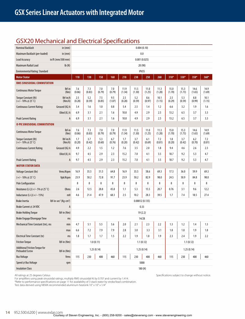
GSX20 Mechanical and Electrical SpecificationsNominal Backlash in (mm) 0.004 (0.10)
Maximum Backlash (pre-loaded) in (mm) 0.0
Lead Accuracy in/ft (mm/300 mm) 0.001 (0.025)
Maximum Radial Load lb (N) 20 (90)
Environmental Rating: Standard IP65S
Motor Stator 118 138 158 168 218 238 258 268 318* 338* 358* 368*
RMS SINUSOIDAL COMMUTATION
Continuous Motor Torque lbf-in (Nm)
7.6(0.86)
7.3(0.83)
7.0(0.79)
7.0(0.79)
11.9 (1.34)
11.5 (1.30)
11.0 (1.25)
11.3 (1.28)
15.0 (1.70)
15.3 (1.73)
14.6 (1.65)
14.9 (1.69)
Torque Constant (Kt)(+/– 10% @ 25˚C)
lbf-in/A(Nm/A)
2.5(0.28)
5.2(0.59)
7.5(0.85)
9.5 (1.07)
2.5 (0.28)
5.2 (0.59)
8.6 (0.97)
10.1 (1.15)
2.5 (0.29)
5.3 (0.59)
8.8 (0.99)
10.1 (1.15)
Continuous Current Rating: Greased (IG) A 3.4 1.6 1.0 0.8 5.4 2.5 1.4 1.2 6.6 3.2 1.9 1.6
Oiled (IL) A 6.9 3.1 2.1 1.6 10.8 4.9 2.9 2.5 13.2 6.5 3.7 3.3
Peak Current Rating A 6.9 3.1 2.1 1.6 10.8 4.9 2.9 2.5 13.2 6.5 3.7 3.3
O-PK SINUSOIDAL COMMUTATION
Continuous Motor Torque lbf-in(Nm)
7.6 (0.86)
7.3 (0.83)
7.0 (0.79)
7.0(0.79)
11.9 (1.34)
11.5 (1.30)
11.0 (1.25)
11.3 (1.28)
15.0 (1.70)
15.3 (1.73)
14.6 (1.65)
14.9 (1.69)
Torque Constant (Kt)(+/– 10% @ 25˚C)
lbf-in/A(Nm/A)
1.7(0.20)
3.7(0.42)
5.3(0.60)
6.7(0.76)
1.7(0.20)
3.7(0.42)
6.1(0.69)
7.2(0.81)
1.8(0.20)
3.7(0.42)
6.2(0.70)
7.2(0.81)
Continuous Current Rating Greased (IG) A 4.9 2.2 1.5 1.2 7.6 3.5 2.0 1.8 9.4 4.6 2.6 2.3
Oiled (IL) A 9.7 4.5 2.9 2.3 15.2 7.0 4.1 3.5 18.7 9.2 5.3 4.7
Peak Current Rating A 9.7 4.5 2.9 2.3 15.2 7.0 4.1 3.5 18.7 9.2 5.3 4.7
MOTOR STATOR DATA
Voltage Constant (Ke) Vrms/Krpm 16.9 35.5 51.5 64.8 16.9 35.5 58.6 69.3 17.3 36.0 59.9 69.3
(+/– 10% @ 25˚C) Vpk/Krpm 23.9 50.2 72.8 91.7 23.9 50.2 82.9 98.0 24.5 50.9 84.8 98.0
Pole Configuration 8 8 8 8 8 8 8 8 8 8 8 8
Resistance (L-L)(+/– 5% @ 25˚C) Ohms 2.6 12.5 28.8 45.8 1.1 5.3 15.5 20.7 0.76 3.1 9.6 12.2
Inductance (L-L)(+/– 15%) mH 4.6 21.4 47.9 68.3 2.5 10.2 28.3 39.5 1.7 7.4 18.5 27.4
Brake Inertia lbf-in-sec2 (Kg-cm2) 0.00012 (0.135)
Brake Current @ 24 VDC A 0.33
Brake Holding Torque lbf-in (Nm) 19 (2.2)
Brake Engage/Disengage Time ms 14/28
Mechanical Time Constant (tm), ms min 4.7 5.1 5.5 5.6 2.0 2.1 2.3 2.2 1.3 1.2 1.4 1.3
max 6.6 7.2 7.9 7.9 2.8 3.0 3.3 3.1 1.8 1.8 1.9 1.8
Electrical Time Constant (te) ms 1.8 1.7 1.7 1.5 2.2 1.9 1.8 1.9 2.3 2.4 1.9 2.2
Friction Torque lbf-in (Nm) 1.0 (0.11) 1.1 (0.12) 1.1 (0.12)
Additional Friction Torque for Preloaded Screw lbf-in (Nm) 1.25 (0.14) 1.25 (0.14) 1.25 (0.14)
Bus Voltage Vrms 115 230 400 460 115 230 400 460 115 230 400 460
Speed @ Bus Voltage rpm 5000
Insulation Class 180 (H)
All ratings at 25 degrees Celsius Specifications subject to change without notice.For amplifiers using peak sinusoidal ratings, multiply RMS sinusoidal Kt by 0.707 and current by 1.414.*Refer to performance specifications on page 11 for availability of 3 stack stator by stroke/lead combination.Test data derived using NEMA recommended aluminum heatsink 10" x 10" x 1/4"
GSX Series Linear Actuators with Integrated Motor
Courtesy of Steven Engineering, Inc. - (800) 258-9200 - [email protected] - www.stevenengineering.com

952.500.6200 | www.exlar.com 15
GSX30 Mechanical and Electrical SpecificationsNominal Backlash in (mm) 0.004 (0.10)
Maximum Backlash (pre-loaded) in (mm) 0.0
Lead Accuracy in/ft (mm/300 mm) 0.001 (0.025)
Maximum Radial Load lb (N) 30 (134)
Environmental Rating: Standard IP65S
Motor Stator 118 138 158 168 218 238 258 268 318* 338* 358* 368*
RMS SINUSOIDAL COMMUTATION
Continuous Motor Torque lbf-in(Nm)
16.9 (1.91)
16.8 (1.90)
16.3 (1.84)
16.0 (1.81)
26.9 (3.04)
27.1 (3.06)
26.7 (3.01)
27.0 (3.05)
38.7 (4.37)
38.2 (4.32)
36.2 (4.09)
36.3(4.10)
Torque Constant (Kt)(+/– 10% @ 25˚C)
lbf-in/A(Nm/A)
4.4(0.49)
8.7(0.99)
15.5(1.75)
17.5(1.97)
4.4(0.49)
8.7(0.99)
15.5(1.75)
17.5(1.97)
4.4(0.50)
8.7(0.98)
15.6(1.77)
17.5(1.98)
Continuous Current Rating: Greased (IG) A 4.3 2.2 1.2 1.0 6.9 3.5 1.9 1.7 9.7 4.9 2.6 2.3
Oiled (IL) A 8.6 4.3 2.4 2.0 13.8 6.9 3.8 3.4 19.5 9.9 5.2 4.6
Peak Current Rating A 8.6 4.3 2.4 2.0 13.8 6.9 3.8 3.4 19.5 9.9 5.2 4.6
O-PK SINUSOIDAL COMMUTATION
Continuous Motor Torque lbf-in(Nm)
16.9 (1.91)
16.8 (1.90)
16.3 (1.84)
16.0 (1.81)
26.9 (3.04)
27.1 (3.06)
26.7(3.01)
27.0 (3.05)
38.7 (4.37)
38.2 (4.32)
36.2 (4.09)
36.3(4.10)
Torque Constant (Kt)(+/– 10% @ 25˚C)
lbf-in/A(Nm/A)
3.1(0.35)
6.2(0.70)
11.0(1.24)
12.4(1.40)
3.1(0.35)
6.2(0.70)
11.0(1.24)
12.4(1.40)
3.1(0.35)
6.1(0.69)
11.11.25
12.4(1.40)
Continuous Current Rating: Greased (IG) A 6.1 3.0 1.7 1.4 9.7 4.9 2.7 2.4 13.8 7.0 3.7 3.3
Oiled (IL) A 12.2 6.1 3.3 2.9 19.5 9.8 5.4 4.9 27.6 13.9 7.3 6.5
Peak Current Rating A 12.2 6.1 3.3 2.9 19.5 9.8 5.4 4.9 27.6 13.9 7.3 6.5
MOTOR STATOR DATA
Voltage Constant (Ke) Vrms/Krpm 29.8 59.7 105.8 119.3 29.8 59.7 105.8 119.3 30.3 59.2 106.8 119.8
(+/– 10% @ 25˚C) Vpk/Krpm 42.2 84.4 149.7 168.7 42.2 84.4 149.7 168.7 42.9 83.7 151.0 169.4
Pole Configuration 8 8 8 8 8 8 8 8 8 8 8 8
Resistance (L-L)(+/– 5% @ 25˚C) Ohms 2.7 10.8 36.3 47.9 1.1 4.4 14.1 17.6 0.65 2.6 9.3 11.6
Inductance (L-L)(+/– 15%) mH 7.7 30.7 96.8 123.0 3.7 14.7 46.2 58.7 2.5 9.5 30.9 38.8
Brake Inertia lbf-in-sec2 (Kg-cm2) 0.00033 (0.38)
Brake Current @ 24 VDC A 0.5
Brake Holding Torque lbf-in (Nm) 70 (8)
Brake Engage/Disengage Time ms 19/29
Mechanical Time Constant (tm), ms min 4.9 4.9 5.2 5.4 2.0 2.0 2.0 2.0 1.1 1.2 1.3 1.3
max 9.4 9.5 10.1 10.5 3.9 3.8 3.9 3.8 2.2 2.3 2.5 2.5
Electrical Time Constant (te) ms 2.9 2.8 2.7 2.6 3.3 3.4 3.3 3.3 3.8 3.7 3.3 3.3
Friction Torque lbf-in (Nm) 1.5 (0.17) 1.7 (0.19) 1.9 (0.21)
Additional Friction Torque for Preloaded Screw lbf-in (Nm) 1.75 (0.20) 1.75 (0.20) 1.75 (0.20)
Bus Voltage Vrms 115 230 400 460 115 230 400 460 115 230 400 460
Speed @ Bus Voltage rpm 3000
Insulation Class 180 (H)
All ratings at 25 degrees Celsius Specifications subject to change without notice.For amplifiers using peak sinusoidal ratings, multiply RMS sinusoidal Kt by 0.707 and current by 1.414.*Refer to performance specifications on page 11 for availability of 3 stack stator by stroke/lead combination.Test data derived using NEMA recommended aluminum heatsink 10" x 10" x 3/8"
GSX Series Linear Actuators with Integrated Motor
GSX
Ser
ies
Courtesy of Steven Engineering, Inc. - (800) 258-9200 - [email protected] - www.stevenengineering.com

16 952.500.6200 | www.exlar.com
GSX40 Mechanical and Electrical SpecificationsNominal Backlash in (mm) 0.004 (0.10)
Maximum Backlash (pre-loaded) in (mm) 0.0
Lead Accuracy in/ft (mm/300 mm) 0.001 (0.025)
Maximum Radial Load lb (N) 40 (179)
Environmental Rating: Standard IP65S
Motor Stator 118 138 158 168 218 238 258 268 338* 358* 368*
RMS SINUSOIDAL COMMUTATION
Continuous Motor Torque lbf-in(Nm)
47.5 (5.37)
47.5 (5.36)
45.9 (5.19)
45.4(5.13)
75.1 (8.49)
78.6 (8.89)
78.7 (8.89)
79.5 (8.99)
106.9(12.08)
105.3(11.90)
106.9 (12.08)
Torque Constant (Kt)(+/– 10% @ 25˚C)
lbf-in/A(Nm/A)
4.1(0.46)
8.2(0.93)
14.5(1.64)
16.8(1.90)
4.1(0.46)
8.2(0.93)
14.5(1.64)
16.8(1.90)
8.4(0.95)
14.5(1.64)
16.8 (1.90)
Continuous Current Rating: Greased (IG) A 12.9 6.5 3.5 3.0 20.5 10.7 6.0 5.3 14.2 8.1 7.1
Oiled (IL) A 25.9 12.9 7.1 6.0 40.9 21.4 12.1 10.6 28.5 16.2 14.2
Peak Current Rating A 25.9 12.9 7.1 6.0 40.9 21.4 12.1 10.6 28.5 16.2 14.2
O-PK SINUSOIDAL COMMUTATION
Continuous Motor Torque lbf-in (Nm)
47.5 (5.37)
47.5(5.36)
45.9(5.19)
45.4(5.13)
75.1 (8.49)
78.6 (8.89)
78.7 (8.89)
79.5 (8.99)
106.9 (12.08)
105.3 (11.90)
106.9 (12.08)
Torque Constant (Kt)(+/– 10% @ 25˚C)
lbf-in/A (Nm/A)
2.9(0.33)
5.8(0.66)
10.3(1.16)
11.9(1.34)
2.9(0.33)
5.8(0.66)
10.3(1.16)
11.9(1.34)
5.9(0.67)
10.3(1.16)
11.9(1.34)
Continuous Current Rating: Greased (IG) A 18.3 9.1 5.0 4.3 28.9 15.1 8.5 7.5 20.1 11.4 10.1
Oiled (IL) A 36.6 18.3 10.0 8.6 57.9 30.3 17.1 15.0 40.3 22.9 20.1
Peak Current Rating A 36.6 18.3 10.0 8.6 57.9 30.3 17.1 15.0 40.3 22.9 20.1
MOTOR STATOR DATA
Voltage Constant (Ke) Vrms/Krpm 28.0 56.0 99.3 114.6 28.0 56.0 99.3 114.6 57.3 99.3 114.6
(+/– 10% @ 25˚C) Vpk/Krpm 39.6 79.2 140.5 162.1 39.6 79.2 140.5 162.1 81.0 140.5 162.1
Pole Configuration 8 8 8 8 8 8 8 8 8 8 8
Resistance (L-L)(+/– 5% @ 25˚C) Ohms 0.42 1.7 5.7 7.8 0.2 0.72 2.26 3.0 0.5 1.52 2.0
Inductance (L-L)(+/– 15%) mH 3.0 11.9 37.5 49.9 1.2 5.4 18.2 23.1 4.0 12.0 16.0
Brake Inertia lbf-in-sec2 (Kg-cm2) 0.00096 (1.08)
Brake Current @ 24 VDC A 0.67
Brake Holding Torque lbf-in (Nm) 97 (11)
Brake Engage/Disengage Time ms 20/29
Mechanical Time Constant (tm), ms min 4.5 4.5 4.8 4.9 2.1 1.9 1.9 1.9 1.2 1.3 1.2
max 6.0 6.0 6.4 6.6 2.8 2.6 2.6 2.5 1.7 1.7 1.7
Electrical Time Constant (te) ms 7.0 7.0 6.6 6.4 5.9 7.5 8.0 7.8 8.2 7.9 8.2
Friction Torque lbf-in (Nm) 2.7 (0.31) 3.0 (0.34) 3.5 (0.40)
Additional Friction Torque for Preloaded Screw lbf-in (Nm) 4.5 (0.51) 4.5 (0.51) 4.5 (0.51)
Bus Voltage Vrms 115 230 400 460 115 230 400 460 230 400 460
Speed @ Bus Voltage rpm 3000
Insulation Class 180 (H)
All ratings at 25 degrees Celsius Specifications subject to change without notice.For amplifiers using peak sinusoidal ratings, multiply RMS sinusoidal Kt by 0.707 and current by 1.414.*Refer to performance specifications on page 12 for availability of 3 stack stator by stroke/lead combination.Test data derived using NEMA recommended aluminum heatsink 12" x 12" x 1/2"
GSX Series Linear Actuators with Integrated Motor
Courtesy of Steven Engineering, Inc. - (800) 258-9200 - [email protected] - www.stevenengineering.com

FT80 Series Linear Actuators
952.500.6200 | www.exlar.com 17
GSX50 Mechanical and Electrical SpecificationsNominal Backlash in (mm) 0.004 (0.10)
Maximum Backlash (pre-loaded) in (mm) 0.0
Lead Accuracy in/ft (mm/300 mm) 0.001 (0.025)
Maximum Radial Load lb (N) 75 (337)
Environmental Rating: Standard IP65S
Motor Stator 138 158 168 238 258 268 338 358 368
RMS SINUSOIDAL COMMUTATION
Continuous Motor Torque lbf-in (Nm)
107.2 (12.12)
104.8 (11.84)
109.4(12.36)
179.9 (20.32)
178.8 (20.20)
177.8 (20.09)
233.3 (26.36)
237.2 (26.80)
238.3(26.93)
Torque Constant (Kt)(+/– 10% @ 25˚C)
lbf-in/A (Nm/A)
11.8(1.33)
20.2(2.28)
23.6(2.67)
11.8(1.33)
20.2(2.28)
23.6(2.67)
12.0(1.36)
20.2(2.28)
24.0(2.71)
Continuous Current Rating: Greased (IG) A 10.2 5.8 5.2 17.0 9.9 8.4 21.7 13.1 11.1
Oiled (IL) A 20.3 11.6 10.4 34.1 19.8 16.8 43.4 26.2 22.2
Peak Current Rating A 20.3 11.6 10.4 34.1 19.8 16.8 43.4 26.2 22.2
O-PK SINUSOIDAL COMMUTATION
Continuous Motor Torque lbf-in (Nm)
107.2 (12.12)
104.8 (11.84)
109.4 (12.36)
179.9 (20.32)
178.8 (20.20)
177.8 (20.09)
233.3(26.36)
237.2 (26.80)
238.3(26.93)
Torque Constant (Kt)(+/– 10% @ 25˚C)
lbf-in/A (Nm/A)
8.3(.94)
14.3(1.62)
16.7(1.88)
8.3(0.94)
14.3(1.62)
16.7(1.88)
8.5(0.96)
14.3(1.62)
17.0(1.92)
Continuous Current Rating: Greased (IG) A 14.4 8.2 7.3 24.1 14.0 11.9 30.7 18.5 15.7
Oiled (IL) A 28.7 216.4 14.7 48.2 27.9 23.8 61.4 37.1 31.4
Peak Current Rating A 28.7 16.4 14.7 48.2 27.9 23.8 61.4 37.1 31.4
MOTOR STATOR DATA
Voltage Constant (Ke) Vrms/Krpm 80.6 138.1 161.1 80.6 138.1 161.1 82.0 138.1 164.0
(+/– 10% @ 25˚C) Vpk/Krpm 113.9 195.3 227.9 113.9 195.3 227.9 116.0 195.3 232.0
Pole Configuration 8 8 8 8 8 8 8 8 8
Resistance (L-L)(+/– 5% @ 25˚C) Ohms 0.87 2.68 3.34 0.34 1.01 1.39 0.22 0.61 0.86
Inductance (L-L)(+/– 15%) mH 21.7 63.9 78.3 10.4 27.6 41.5 6.3 17.8 28.2
Brake Inertia lbf-in-sec2 (Kg-cm2) 0.0084 (9.5)
Brake Current @ 24 VDC A 1
Brake Holding Torque lbf-in (Nm) 354 (40)
Brake Engage/Disengage Time ms 25/73
Mechanical Time Constant (tm), ms min 2.2 2.3 2.1 0.9 0.9 0.9 0.5 0.5 0.5
max 2.8 3.0 2.7 1.1 1.1 1.1 0.7 0.7 0.7
Electrical Time Constant (te) ms 25.0 23.9 23.4 30.6 27.3 29.9 28.0 29.0 32.9
Friction Torque lbf-in (Nm) 4.1 (0.46) 4.6 (0.53) 5.3 (0.60)
Additional Friction Torque for Preloaded Screw lbf-in (Nm) 6.00 (0.68) 6.00 (0.68) 6.00 (0.68)
Bus Voltage Vrms 230 400 460 230 400 460 230 400 460
Speed @ Bus Voltage rpm 2400
Insulation Class 180 (H)
For amplifiers using peak sinusoidal ratings, multiply RMS sinusoidal Kt by 0.707 and current by 1.414. Specifications subject to change without notice.Test data derived using NEMA recommended aluminum heatsink 12" x 12" x 1/2"
GSX Series Linear Actuators with Integrated Motor
GSX
Ser
ies
Courtesy of Steven Engineering, Inc. - (800) 258-9200 - [email protected] - www.stevenengineering.com

18 952.500.6200 | www.exlar.com
GSX60 Mechanical and Electrical SpecificationsNominal Backlash in (mm) 0.004 (0.10)
Maximum Backlash (pre-loaded) in (mm) 0.0
Lead Accuracy in/ft (mm/300 mm) 0.001 (0.025)
Maximum Radial Load lb (N) 100 (445)
Environmental Rating: Standard IP65S
Motor Stator 138 158 168 238 258 268 358 368
RMS SINUSOIDAL COMMUTATION
Continuous Motor Torque lbf-in (Nm)
254.2(28.72)
249.9 (28.23)
261.9(29.59)
424.8 (47.99)
423.0 (47.79)
427.5 (48.30)
595.6(67.29)
615.0 (69.49)
Torque Constant (Kt)(+/– 10% @ 25˚C)
lbf-in/A (Nm/A)
12.6(1.42)
21.8(2.46)
25.2(2.84)
12.6(1.42)
21.8(2.46)
25.2(2.84)
21.4(2.42)
25.2(2.84)
Continuous Current Rating: Greased (IG) A 22.6 12.8 11.6 37.7 21.7 19.0 31.1 27.3
Oiled (IL) A 45.2 25.6 23.3 75.5 43.4 38.0 62.2 54.6
Peak Current Rating A 45.2 25.6 23.3 75.5 43.4 38.0 62.2 54.6
O-PK SINUSOIDAL COMMUTATION
Continuous Motor Torque lbf-in (Nm)
254.2 (28.72)
249.9(28.23)
261.9 (29.59)
424.8 (47.99)
423.0 (47.79)
427.5(48.30)
595.6(67.29)
611.6(69.10)
Torque Constant (Kt)(+/– 10% @ 25˚C)
lbf-in/A (Nm/A)
8.9(1.01)
15.4(1.74)
17.8(2.01)
8.9(1.01)
15.4(1.74)
17.8(2.01)
15.1(1.71)
17.8(2.01)
Continuous Current Rating: Greased (IG) A 31.9 18.1 16.4 53.4 30.7 26.8 44.0 38.4
Oiled (IL) A 63.9 36.2 32.9 106.7 61.3 53.7 88.0 76.8
Peak Current Rating A 63.9 36.2 32.9 106.7 61.3 53.7 88.0 76.8
MOTOR STATOR DATA
Voltage Constant (Ke) Vrms/Krpm 85.9 148.9 171.8 85.9 148.9 171.8 146.1 171.8
(+/– 10% @ 25˚C) Vpk/Krpm 121.5 210.6 243.0 121.5 210.6 243.0 206.6 243.0
Pole Configuration 8 8 8 8 8 8 8 8
Resistance (L-L)(+/– 5% @ 25˚C) Ohms 0.3 1.0 1.2 0.13 0.41 0.5 0.23 0.3
Inductance (L-L)(+/– 15%) mH 8.3 24.8 29.4 3.9 11.8 15.8 7.5 10.3
Brake Inertia lbf-in-sec2 (Kg-cm2) 0.02815 (31.8)
Brake Current @ 24 VDC A 1.45
Brake Holding Torque lbf-in (Nm) 708 (80)
Brake Engage/Disengage Time ms 53/97
Mechanical Time Constant (tm), ms min 3.9 4.0 3.6 1.6 1.6 1.6 1.0 0.9
max 4.3 4.5 4.1 1.8 1.8 1.8 1.1 1.0
Electrical Time Constant (te) ms 25.4 24.6 24.0 29.4 29.1 29.8 32.1 33.8
Friction Torque lbf-in (Nm) 8.1 (0.91) 10.8 (1.22) 14.5 (1.64)
Additional Friction Torque for Preloaded Screw lbf-in (Nm) 6.00 (0.68) 6.00 (0.68) 6.00 (0.68)
Bus Voltage Vrms 230 400 460 230 400 460 400 460
Speed @ Bus Voltage rpm 2400
Insulation Class 180 (H)
For amplifiers using peak sinusoidal ratings, multiply RMS sinusoidal Kt by 0.707 and current by 1.414. Specifications subject to change without notice.Test data derived using NEMA recommended aluminum heatsink 16" x 16" x 1"The GSX60-06 can only accommodate a single stack stator.
GSX Series Linear Actuators with Integrated Motor
Courtesy of Steven Engineering, Inc. - (800) 258-9200 - [email protected] - www.stevenengineering.com

FT80 Series Linear Actuators
952.500.6200 | www.exlar.com 19
GSX Series actuators include an integrated brushless servo motor. Exlar’s unique design gives users a variety of the feedback configuration options so GSX units can be powered by almost any brushless motor amplifier on the market.
This flexibility means GSX actuators can be incorporated into today’s highest performance single and multi-axis
motion control systems. In anything from food and beverage packaging, to multi-axis turning centers, to aircraft assembly, GSX Series units show incredible performance and durability.
The schematic below shows the typical connections for a single axis system with actuator and servo amplifier.
GSX Series – System Configuration
Drawings subject to change. Consult Exlar for certified drawings.
Brake Cable (if needed)
Motor Power Cable
Motor Feedback Cable
To linepower
Typical ServoAmplifier
Mot
or a
nd P
ower
con
nect
ions
Feed
back
Con
nect
ions
I/O C
onne
ctio
ns
GSX Series Linear Actuators with Integrated Motor
GSX
Ser
ies
Courtesy of Steven Engineering, Inc. - (800) 258-9200 - [email protected] - www.stevenengineering.com

20 952.500.6200 | www.exlar.com
Fastening and JoiningRivetingBag SealingThermoformingWeldingFillersFormersClampingMoldingPrecision GrindersPrecision Pressing Interference Detection
Die CuttersInjection MoldingTube BendingStampingTest Stand LiftsTension ControlWire WindingParts ClampingDispensersCircuit Board TestingBlood Processing
GSX SeriesForce Measuring ActuatorsExlar offers select models of its GSX Series actuators with integral force measuring capability. This option is available in the GSX30, 40, 50 & 60 models.
A load cell is embedded within the actuator allowing it to directly measure the force being applied by the actuator’s output rod. The strain gauge load sensor used to measure applied force is mounted inside the actuator’s case, protecting it from external damage and guaranteeing accurate and consistent force data.
A separate connector is supplied for connecting the internal load cell to an external strain conditioner/amplifier required to excite the strain gauge sensor. Exlar can offer strain gauge conditioners to provide a high level output signal, either 0-10V or 4-20mA.
Alternatively, any one of numerous conditioners/amplifiers available can be used for this purpose.
Applications
Features/Characteristics
Front flange or rear clevis mount
Bi-directional load measurement
Integrated strain gauge load cell
2 mV/V sensitivity
+/- 2% linearity
+/- 0.5% repeatability
Hysteresis, 1% nominal
250 Hz frequency response
Factory calibrated
Compatible with standard gauge monitors and PLC strain gauge input cards
Requires 10 VDC external excitation
Totally enclosed within the actuator’s sealed housing, and connectorized for ease of use
Strain Gauge Amplifier, (purchased separately)
GSX Series Linear Actuator
GSX Series Actuators with Integrated Motor
20 952.500.6200 | www.exlar.com
Consult your local sales representative to discuss your application if you plan to use the force measuring option with your GSX actuator. Actuators with force measuring should include an XT in the model mask.
Courtesy of Steven Engineering, Inc. - (800) 258-9200 - [email protected] - www.stevenengineering.com
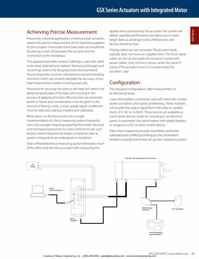
Achieving Precise MeasurementFrequently industrial applications involving linear actuation require the precise measurement of the load being applied by the actuator. Historically these have been accomplished by placing a load cell between the actuator and the connection to the workpiece.
This approach provides several challenges. Load cells need to be sized, selected and ordered. Mechanical linkages and mountings need to be designed, built and assembled. Precise alignment must be maintained to prevent bending moments which can severely degrade the accuracy of any load measurement system involving load cells.
Provisions for securing the wires to the load cell need to be designed particularly if the load cell is moving in the process of applying the force. Moving wires are extremely prone to failure and consideration must be given to the amount of flexing. Lastly, a strain gauge signal conditioner must be selected, ordered, installed and calibrated.
What seems on the front end to be a simple implementation of a force measuring system frequently turns into a project requiring expertise from both electrical and mechanical personnel. It is also common to see such projects extend beyond the target completion date as system components are redesigned or reordered.
Exlar’s embedded force measuring option eliminates much of the effort and the risk associated with measuring the
applied force produced by the actuator. This system will deliver specified performance and allow you to meet target dates as all design work is field-proven and factory-tested by Exlar.
Flexing cables are not necessary. The actuator body typically does not move as it applies force. The force signal cable can be run alongside the actuator’s central and power cables. And, the force sensor carries the same IP rating of the actuator since it is located inside the actuator’s case.
ConfigurationThe standard configurations offer measurement of bi-directional loads.
Load cell amplifiers commonly used with load cells contain power, excitation, and signal conditioning. These modules will amplify the output signal from milli-volts to useable levels of 0-10V or 4-20mA. These devices are available as stand-alone devices made for mounting in an electrical panel, incorporated into panel meters with digital displays, or integral to a PLC or other control device.
Exlar’s force measuring actuator assemblies are factory calibrated and certified providing you the information needed to quickly and simply set up your measuring system.
Actuator with Embedded Force Sensor
SerialCommunications
ServoAmplifier
Strain GaugeAmplifier
Force MonitoringInstrumentation
10 V Excitation
ACPower
GSX Series Actuators with Integrated Motor
952.500.6200 | www.exlar.com 21
GSX
Ser
ies
Courtesy of Steven Engineering, Inc. - (800) 258-9200 - [email protected] - www.stevenengineering.com

22 952.500.6200 | www.exlar.com
Performance SpecificationsGSX Series
Linearity (% of actuator rated force) +/- 2%
Repeatibility +/- 0.5%
Hysteresis 2% Nominal
Frequency Response* >250 Hz
Overload Capability 1.5x Full Scale
Sensitivity (nominal) 2 mV/V
Excitation +/-10V
Input Impedance 388 Ohms
Output Impedance 350 Ohms
* This is the frequency response of a “locked rotor” force measuring actuator. Frequency response of the load cell/actuator system will depend on total system inertia and the motor and drive amplifier powering the system.
GSX Actuator with Flange-Mount Force Measurement
Load Cell
GSX Actuator with Clevis-Mount Force Measurement
Performance SpecificationsModel Available Lead inch
(mm) Force Range lbf (N) Linearity
GSX30 01 = 0.1 (2.54)02 = 0.2 (5.08)
50-1300 (222-5783)50-900 (222-4004) +/- 2%
GSX40 01 = 0.1 (2.54)02 = 0.2 (5.08)
150-3800 (667-16903)150-2600 (667-11565) +/- 2%
GSX50 01 = 0.1 (2.54)02 = 0.2 (5.08)
250-8000 (1112-35586)250-5600 (1112-24910) +/- 2%
GSX60 03 = 0.25 (6.35) 500-10000 (2224-44482) +/- 2%
Example Calibration and Load InformationActuator with Load Cell (GSX40 Only)
Serial No 6090825
Type Compression Load Cell
Calibration Factor 2.1809 mV/V Full Scale
Calibration Full Scale Load 20,000 Pounds
Excitation Voltage +/-10V
Linearity <2%
Rated Force 3800 Pounds
See Operation Manual for wiring and operation instructions
Force Measuring Actuator Range/CapacityFrame 30 40 50 60
GSX Series ForceMeasurement Range / Capacity lbf (kN)
50 - 1300(0.2 - 5.78)
150 - 3800(0.67 - 16.5)
250 - 8000(1.1- 36)
500 - 10000(2.2 - 45)
GSX Series Actuators with Integrated Motor
Load Cell
Courtesy of Steven Engineering, Inc. - (800) 258-9200 - [email protected] - www.stevenengineering.com

952.500.6200 | www.exlar.com 23
- excitation
- signal
+ signal
+ excitation
V
V
earth
-10V
+10VDC
output 0/4.20mA
Grid output
output +-10V
capacitorforlowpass filtre
Typical Strain Gauge AmplifierLoad Cell
121110
987
654
321
Power
Gain
Offset
Force MeasurementAll Exlar precision load measuring designs are incremental in nature. By this it is intended that force measurements always be conducted as the change in the signal output between the start of each load producing motion and its completion. The force measuring option is not intended to be used as an absolute measurement of force being applied over extended time periods.
Exlar can separately provide strain gauge amplifiers that offer a convenient method for accurately and reliably measuring the resistance change per cycle of the strain gauge load cell embedded in a GSX Series actuator.
These units convert the small mV changes in load cell output to a 0-10 volt or 4-20 mA signal which is proportional to the load or tension being applied by the actuator. These amplifiers can be DIN rail or panel mountable, with or without displays.
Basic Strain Gauge Function• The strain gauge acts as a resistor in one leg of a Wheatstone bridge
• The strain gauge amplifier applies voltage across the bridge at A-A (excitation voltage), causing current to flow through the bridge
• The resistance of the strain gauge changes as a function of the force being applied
• The output voltage across B-B changes as a function of the force being applied to the load cell.
Wheatstone Bridge
Typical Features
• DIN rail panel
• 24 Volt power
• +/- 10 VDC or 0/4-20 mA output
• Simple gain & offset adjustments
• Auto calibration
• Simple filtering options
• With or without display
Typical System Wiring Diagram
V
R3
R2R1
BB
A
A
strain gauge
input voltage(+/- 10 Vdc usually) Output Voltage (V)
GSX Series Actuators with Integrated Motor
GSX
Ser
ies
Courtesy of Steven Engineering, Inc. - (800) 258-9200 - [email protected] - www.stevenengineering.com
Consult your local sales representative to discuss your application if you plan to use oil cooling with your GSX actuator.
All actuators to be used with oil cooling should have XL in the model mask.
Exlar GSX actuators are normally delivered with high performance synthetic grease as a lubricant. The application of grease for the rollerscrew mechanism and bearings has been proven adequate in thousands of applications over 25 years. However, in applications where the actuator is operated under high load, high speed and/or high duty cycle for extended periods of time the grease will degrade prematurely and will eventually fail to provide the lubrication needed to maintain operating efficiency and integrity of the rollerscrew and bearings. Continued operation of the actuator after the grease has broken down will cause premature failure of the device.
An ideal way to both lubricate and cool a GS Series actuator in high performance applications is to flow a small amount of oil at low pressure through the actuator while in operation. A small amount of oil flow through the actuator can, in many cases, allow operation of the actuator beyond normal continuous rated power levels. Oil flow lubrication has been has been used successfully and extensively in the field, allowing Exlar actuators to deliver thousands of hours of service between re-lubrication
intervals in the most arduous of applications.
Oil lubrication also significantly reduces actuator maintenance, saving valuable production time. With a recirculating oil system, lubricating oil is easily changed without having to access or dismount the actuator, and the ability to monitor oil condition can extend the usable life of the actuator by keeping the lubrication clean and fresh.
Some special application and actuator configuration considerations must be addressed prior to selecting and ordering a GS actuator with oil lubrication. As a result, all applications where oil lubricant is being considered must be discussed with Exlar Application Engineering prior to purchase.
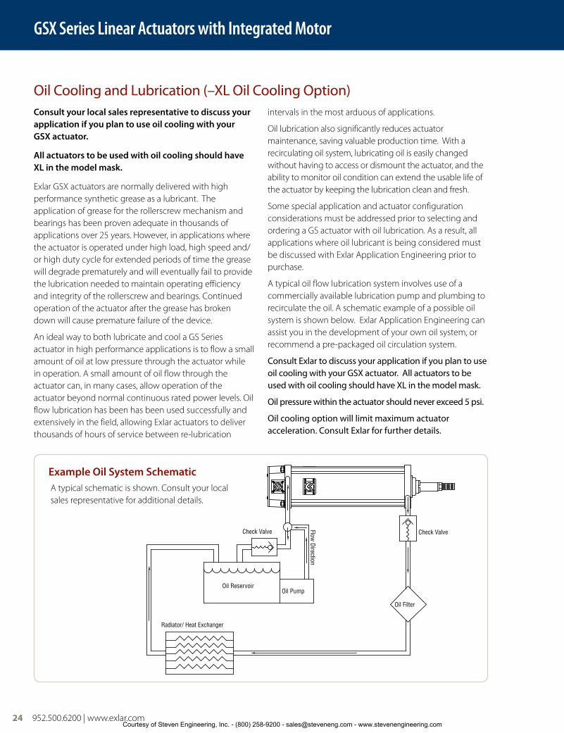
A typical oil flow lubrication system involves use of a commercially available lubrication pump and plumbing to recirculate the oil. A schematic example of a possible oil system is shown below. Exlar Application Engineering can assist you in the development of your own oil system, or recommend a pre-packaged oil circulation system.
Consult Exlar to discuss your application if you plan to use oil cooling with your GSX actuator. All actuators to be used with oil cooling should have XL in the model mask.
Oil pressure within the actuator should never exceed 5 psi.
Oil cooling option will limit maximum actuator acceleration. Consult Exlar for further details.
Oil Cooling and Lubrication (–XL Oil Cooling Option)
Radiator/ Heat Exchanger
Oil Filter
Check Valve
Oil Reservoir
Check Valve
Oil Pump
Flow Direction
A typical schematic is shown. Consult your local sales representative for additional details.
Example Oil System Schematic
GSX Series Linear Actuators with Integrated Motor
24 952.500.6200 | www.exlar.comCourtesy of Steven Engineering, Inc. - (800) 258-9200 - [email protected] - www.stevenengineering.com

FT80 Series Linear Actuators
952.500.6200 | www.exlar.com 25
Anti-rotation OptionThe unique design of the GSX Series of linear actuators permits the extending rod to rotate. This simplifies actuator setup by allowing the user to rotate the rod and thread it in and out of the actuator for mechanical attachment or system testing.
However, this feature also requires that once setup and testing are completed, the rod be kept from rotating so proper linear motion will be maintained. In most applications the actuator’s load is coupled to linear bearings, or some other support device. In these cases the load cannot rotate, and a separate anti-rotation system is not needed.
For applications in which the load is free to rotate, Exlar offers the anti-rotation systems shown right. Shorter GSX units use an anti-rotation arm on one side of the actuator. Longer strokes (defined above right) use arms on both sides.
Anti-rotation Option GSX/M20, GSX/M30, GSX/M40 and GSX60
Anti-rotation Option GSX50
CB
A
D
E
GøH
F
4.750(120.65)
2.00(50.8)
2.50(63.5)
3.84(97.5)
R1.09(R27.7)
2.13 (54.1)
0.75(19.1)
2.38 (60.5)
ø1.00 (25.4)
Anti-Rotate
GSX50 Linear Actuator
Contact exlar for a certified drawing.and should be used for estimation purposes only.This drawing is subject to change without notice
ALL DIMENSIONS IN INCHESUNLESS OTHERWISE SPECIFIED:
A second anti-rotate arm is used on GSX20, GSX30 and GSX40, 10 inch and longer stroke.
GSX60 uses a single sided anti-rotate for all stroke lengths.
Dims- in (mm) GSX/M20 GSX/M30 GSX/M40 GSX60
A 0.60 (15.2) 0.79 (20.1) 1.25 (31.8) 1.75 (44.5)
B 1.81 (46.0) 2.54 (64.5) 3.78 (96.0) 5.79 (147)
C 0.54 (13.7) 0.71 (18.0) 0.98 (24.9) 1.55 (39.4)
D 1.00 (25.4) 1.30 (33.0) 1.64 (41.7) 1.94 (49.3)
E 0.44 (11.2) 0.44 (11.2) 0.63 (16.0) 0.75 (19.1)
F 0.28 (7.11) 0.32 (8.13) 0.38 (9.65) 0.50 (12.7)
G 0.31 (7.87) 1.69 (42.9) 1.69 (42.9) 2.81 (71.4)
øH 0.37 (9.40) 0.50 (12.7) 0.50 (12.7) 1.00 (25.4)
NOTE: GSX50 actuators use one arm for all stroke lengths.
GSX Series Linear Actuators with Integrated Motor
952.500.6200 | www.exlar.com 25
GSX
Ser
ies
Courtesy of Steven Engineering, Inc. - (800) 258-9200 - [email protected] - www.stevenengineering.com

26 952.500.6200 | www.exlar.com
PF = Preloaded Follower This option offers a true zero backlash follower for the GSX Series actuator. The dynamic load rating of zero backlash, preloaded screws is 63% of the dynamic load rating of the standard non-preloaded screws. The calculated travel life of a preloaded screw will be 25% of the calculated travel life of the same size and lead of a non-preloaded screw for the same application. Preloaded follower is not available with LT linear feedback option.
AR = External Anti-rotate Assembly This option provides a rod and bushing to restrict the actuator rod from rotating when the load is not held by another method. Shorter actuators have single sided anti-rotation attachments. Longer lengths require attachments on both sides for proper operation.
RB = Rear Electric Brake This option provides an internal holding brake for the GSX Series actuators. The brake is spring activated and electrically released.
SR = Splined Main Rod This option provides a main rod manufactured of ball spline shafting, and the front seal and bushing assembly replaced with a ball spline nut to provide the anti-rotate function without using an external mechanism. Rod diameters are the closest metric equivalents to standard Exlar rod sizes. This option is NOT sealed in any way. This option is not suitable for any environment in which contaminants come in contact with the actuator, and may enter the actuator.Note: This option affects overall length and mounting dimensions for GSX
actuators. Consult your local sales representative if using splined main rod. Due to the reduced diameter of the splined main rod on the GSX50, the standard “A”, “F” and “B” rod ends are not available and an “X” should be used in the model mask. Please see Actuator Rod Ends with Splined Main Rod Options on page 36 for dimensions.
PB = Protective Bellows This option provides an accordion style protective bellows to protect the main actuator rod from damage due to abrasives or other contaminants in the environment in which the actuator must survive. The standard material of this bellows is S2 Neoprene Coated Nylon, Sewn Construction. This standard bellows is rated for environmental temperatures of -40 to 250 degrees F. Longer strokes may require the main rod of the actuator to be extended beyond standard length. Not available with extended tie rod mounting option. Please contact your local sales representative for details.
GSX Series Travel Options
Digit 1 - Ingress of Solid ObjectsThe IP rating system provides for 6 levels of protection against solids.
1 Protected against solid objects over 50 mm e.g. hands, large tools.
2 Protected against solid objects over 12.5 mm e.g. hands, large tools.
3 Protected against solid objects over 2.5 mm e.g. wire, small tools.
4 Protected against solid objects over 1.0 mm e.g. wires.
5 Limited protection against dust ingress. (no harmful deposit)
6 Totally protected against dust ingress.
Standard Ratings for Exlar Actuators
The standard IP rating for Exlar Actuators is IP54S or IP65S. Ingress protection is divided into two categories; solids and liquids.
For example, in IP65S the three digits following “IP” represent different forms of environmental influence:
• The first digit represents protection againstingress of solid objects.
• The second digit represents protectionagainst ingress of liquids.
• The suffix digit represents conditions ofmotion during the operation.
Digit 2 - Ingress of LiquidsThe IP rating system provides for 9 levels of protection against liquids.
1 Protected against vertically falling drops of water or condensation.
2 Protected against falling drops of water, if the case is disposed up to 15 degrees from vertical.
3Protected against sprays of water from any direction, even if the case is disposed up to 60 degrees from vertical.
4 Protected against splash water from any direction.
5 Protected against low pressure water jets from any direction. Limited ingress permitted.
6 Protected against high pressure water jets from any direction. Limited ingress permitted.
7 Protected against short periods of immersion in water of 1m or less for 30 minutes or less.
8 Protected against long durations of immersion in water.
9 High-pressure, high-temperature wash-down applications.
Suffix
S Device standing still during operation M Device moving during
operation
GSX Series Linear Actuators with Integrated Motor
26 952.500.6200 | www.exlar.comCourtesy of Steven Engineering, Inc. - (800) 258-9200 - [email protected] - www.stevenengineering.com

952.500.6200 | www.exlar.com 27
HW = Manual Drive, Handwheel This option provides a manual drive handwheel on the side of the actuator. The handwheel has an engage/disengage lever that is tied to an interrupt switch. Not available on GSX20. Also not available with holding brake unless application details have been discussed with your local sales representative.
RD = Manual Drive, Rear Hex This option provides a hex shaft at the rear of the actuator for manual operation. The hex shaft is directly coupled to the motor and can be turned by hand with a compatible wrench. The hex shaft is enclosed by a sealed cap during operation. This option is not available w/absolute feedback. If the application requires a brake, discuss manual drive use with your local sales representative.
SD = Manual Drive, Side Hex This option provides a hex shaft on the side of the actuator. The hex can be turned by hand with a wrench. Not available on GSX20. Also not available with holding brake unless application details have been discussed with your local sales representative.
XT = Special Travel Option Selections The XT Option can be used to specify various special travel options on the GSX Series of Linear Actuators. Because this option can be used to specify many things, it is important that an order including the -XT option spell out in detail, the exact options being selected by the including of the -XT in the model number.
It is recommended that prior to ordering an actuator including the -XT specifier that a quote be obtained through Exlar’s special products application engineers for the desired options, and that quote be referenced on, or included with any order placed.
Force Measuring Option, an XT option provides integral force measuring capability. See page 20-23.
High Temp Protective Bellows, an XT option, provides an accordion style protective bellows to protect the main actuator rod from damage due to abrasives or other contaminants in the environment in which the
actuator must survive. The high temperature material of this bellows is D1 Teflon Coated Fiberglass, Sewn Construction. This standard bellows is rated for environmental temperatures of -67 to 500 degrees F. Longer strokes may require the main rod of the actuator to be extended beyond standard length. Not available with extended tie rod mounting option. Please contact your local sales representative for details.
L1, L2, L3 = Adjustable External Travel Switches This option allows up to 3 external switches to be included with the GSX Series Actuator. These switches provide travel indication to the controller and are adjustable (must purchase external anti-rotate for this option). See page 35 for details.
XL = Non-Standard Lubrication This option provides for indication in the model number that the customer has specified a lubrication other than the standard provided by Exlar, Mobilith SHC220. Specials include other greases including JAX FG-2 food grade, Mobilgrease 28, other non-standard grease, or use of oil cooling.
GSX Series Linear Actuators with Integrated Motor
GSX
Ser
ies
Courtesy of Steven Engineering, Inc. - (800) 258-9200 - [email protected] - www.stevenengineering.com

28 952.500.6200 | www.exlar.com
Motor Speed DesignatorsAll Exlar T-LAM™ motors and actuators carry a standard motor speed designator as defined below. This is representative of the standard base speed of the motor, for the selected bus voltage.
If the model number is created and the location for the motor speed designator is left blank, this is the base speed to which each motor will be manufactured. The model number can also be created including this standard speed designator.
Exlar also provides the flexibility to manufacture all of its T-LAM products with special base speeds to match the customer’s exact application requirements. This may be a higher than standard speed motor, or lower base speed than standard which will allow the customer to get the required torque at a speed optimized to their application and use the minimum amount of current from their amplifier.
The call-out for a special speed is configured in the model number by using a two digit code from 01-99. These numbers represent the number, in hundreds, of RPM that will be the base speed for the particular motor.
For example, a GSX30-0301-OSM-AD1-118-30 motor that normally has a 3000 RPM standard winding can be changed to a 3300 RPM winding by changing the -30 to a -33. It can be changed to a 5000 RPM winding by changing the -30 to a -50.
Changing this speed designator will change the ratings of the motor, and these must be obtained from your local sales representative. Also, it is not possible to produce every possible speed from -01 to -99 for each motor at each voltage so please contact your local sales representative for confirmation of the speed that is desired for the application.
Feedback OptionsLT = ICT including signal conditioner This option provides for an actuator containing an internally mounted ICT transducer spanning the full stroke of the actuator. Inquire with Exlar engineering for details and signal conditioner output preference. Linear feedback is not available in the GSX20; not available with absolute feedback; not available with PF option, and not available with any stroke 14” or greater.
Absolute Feedback Due to the variability in size of some feedback devices, especially absolute feedback devices which are often very large relative to the size of the actuator motor, the actual size of the actuator may differ in length and width from these drawings for feedback types other than standard resolvers and standard encoders. Please consult Exlar for details. In the event that you order an actuator that differs from these standard dimensions, you will be sent a drawing of the final configuration of your actuator for approval.
DesignatorBase
SpeedActuator/
Motor Series
-50
-30
-24
5000 rpm
3000 rpm
2400 rpm
GSX20
GSX30, GSX40
GSX50, GSX60
01-99 Special Speed, Consult Exlar
118
1 stack
115 Vrms
8 Pole Class 180 H
138 230 Vrms158 400 Vrms168 460 Vrms1A8* 24 VDC1B8* 48 VDC1C8* 120 VDC218
2 stack
115 Vrms
8 Pole Class 180 H
238 230 Vrms258 400 Vrms268 460 Vrms2A8* 24 VDC2B8* 48 VDC2C8* 120 VDC318
3 stack
115 Vrms
8 Pole Class 180 H
338 230 Vrms358 400 Vrms368 460 Vrms3A8* 24 VDC3B8* 48 VDC3C8* 120 VDC
* Low voltage stators may be limited to less than catalog rated torque and/or speed. Please contact your local sales representative when ordering this option.
FG = Smooth White Epoxy This option provides for an actuator coated with FDA approved white epoxy.
EN = Electroless Nickel Plating This option provides for an actuator with electroless nickel plating.
SS = Stainless Steel Housing This option provides an actuator with all stainless steel construction. Housing dimensions for this option are not equal to the standard housing. Force, torque and current
ratings are reduced 25% with this option. Please inquire with Exlar for dimensions and ratings.
HC = Type III Hard Coat Anodized, Class I This option provides an actuator with type III hard coat anodized coating. Class I, no dye.
XH = Special Housing Option Any housing option that is not designated by the above codes should be listed as XH and described at time of order. All special options must be discussed with your local sales representative.
GSX Series Linear Actuators with Integrated Motor
Motor OptionsGSX motor options are described with a 3 digit code. The first digit calls out the stack length, the second the rated bus voltage, and the third the number of poles of the motor. Refer to the mechanical/electrical specifications for motor torque and actuator rated force.
Rod End AttachmentsRear Clevis Pin Spherical Rod Eye Rod Eye Rod ClevisSee drawings on pages 36-38. Attachments ordered separate from actuator.
Housing Options
28 952.500.6200 | www.exlar.comCourtesy of Steven Engineering, Inc. - (800) 258-9200 - [email protected] - www.stevenengineering.com

952.500.6200 | www.exlar.com 29
GSX20 Base Actuator
GSX20 Side Mounts or Extended Tie Rod Mount
GSX20 Side Trunnion Mount or Rear Clevis Mount
GSX20 Front or Rear Flange Mount
Oil cooling ports on bottom 1/8" NPT (2X)
1.0025.4
.7519.1
"S" & "D" =Ø .2500+0/-.0005 .25"J" & "K" =Ø 6mm M7 9.0
.256.4
2Dim "B"
"E" = 10-24 UNC"M" = M5 x 0.8
"S" & "D" = 1/4-20 UNC"J" & "K" = M6 x 1.0
"S & "K" = 4X, "D" & "K" = 8X
Ø 2.54664.66
BC
Single Side MountOn This Side
3.1279.1
5.12129.9
1.0025.4
"T" = Ø 1.000 ±.001"Q" = Ø 25mm h7
Ø 1.5038.1
Dim "C"
"C" = Ø .500 +.002/-.001"G" = Ø 12mm +.01/-.06
R.6315.9
Dim "D"
3.7595.3
3.1379.4
2.2456.8
1.7544.5
1.0025.4
Ø .125 +-.001.000
3.18 +.03.00
Ø.2506.35
1.0025.4
.4411.1
.5012.7
3.7595.3
3.1379.4
2.2456.8
1.0025.4
1.7544.5
Ø .125+-.001.000
3.18 +.03.00
Ø .2506.35
1.5038.1
.7519.1
2.2456.9
2.2456.9 1.12
28.4
1.1228.4
.143.7
Ø 1.500 +-.000.003
38.10 -.00.08
1.0025.4
2.0451.7
Dim "A"
2.3660.0
1Dim "E"
Notes:1. Add 1.78 inches to Dims “A” & “D” and to Dim△1 if ordering a brake.2. Models are shown with Exlar standard M23 style connectors (option “I”).
See ordering guide for other connector options.3. Depending on connector and feedback options selected, dimensions
may vary. Consult Exlar for details, or refer to the drawings provided after receipt of order.
4. Drawings subject to change.5. Add .50 inches to Dims “A, C, D, E” and to Dim△2 if ordering splined
main rod.
Dim 3" (76 mm) Strokein (mm)
6" (152 mm) Strokein (mm)
10" (254 mm) Strokein (mm)
12" (305 mm) Strokein (mm)
A 7.8 (198) 10.8 (274) 14.8 (375) 16.8 (426)
B 5.6 (143) 8.6 (219) 12.6 (320) 14.6 (371)
C 3.0 (76) 6.0 (152) 10.0 (254) 12.0 (305)
D 8.8 (223) 11.8 (299) 15.8 (401) 17.8 (452)
E 4.3 (110) 7.3 (186) 11.3 (288) 14.3 (364)
All Dimensions Shown in Inches (mm)
GSX Series Linear Actuators with Integrated Motor
GSX
Ser
ies
Courtesy of Steven Engineering, Inc. - (800) 258-9200 - [email protected] - www.stevenengineering.com

30 952.500.6200 | www.exlar.com
Oil cooling ports on bottom 1/8" NPT front and 1/4" NPT rear.If rear brake is used both ports are 1/8" NPT.
3.0577.4
3.0577.4
1.5238.7
1.5238.7
2.0451.7
2.6366.7
1Dim "E"
Ø 2.000 +-.000.003
50.80 -.00.08
.092.3
1.3233.5 Dim "A"
Ø3.53689.80
BC
Single Side MountOn This Side
.256.4
2 Dim "B"
1.7544.5
.9624.4
"S" & "D" = Ø.2500+0/-.0005 .25"J" & "K" = Ø6mm M7 9.5
"E" = 1/4-20 UNC"M" = M6 x 1.0
"S" & "D" = 1/4-20 UNC"J" & "K" = M6 x 1.0"S & "K" = 4X, "D" & "K" = 8X
"T" =Ø1.000 ±.001"Q" =Ø25mm h7
3.9299.6
1.0025.4
5.92150.4
Dim "C"Dim "D"
R.7519.1
"C" =Ø.750 +.002/-.001"G" =Ø20mm +0/-.07
Ø1.5038.1
2.5063.5
1.2531.8
5.94150.9
5.25133.4
3.6993.7
2.4361.7
3.0577.4
Ø.250 ±.00056.350 ±.013
Ø.39710.08
1.3233.5
.4411.1
.4411.1
3.6993.75.25
133.4
5.94150.9
2.4361.7
3.0577.4
Ø.39710.08
Ø.250 ±.00056.350 ±.013
GSX30 Base Actuator
GSX30 Side Mounts or Extended Tie Rod Mount
GSX30 Side Trunnion Mount or Rear Clevis Mount
GSX30 Front or Rear Flange Mount
Notes:1. Add 1.6 inches to Dims A & D and to Dim△1 if ordering a brake.2. Add 1.20 inches to Dims A, C, D, E and to Dim△2 if ordering a
splined main rod.3. Models are shown with Exlar standard M23 style connectors
(option “I”). See ordering guide for other connector options.4. Due to the size of many absolute encoders, the selection of
such feedback results in a larger package size than is shown in drawings. Consult Exlar for details, or refer to the drawings provided after receipt of order.
5. Drawings subject to change.
Dim 3" (76 mm) Stroke in (mm)
6" (152 mm) Stroke in (mm)
10" (254 mm) Stroke in (mm)
12" (305 mm) Stroke in (mm)
14" (355 mm) Stroke in (mm)
18" (457 mm) Stroke in (mm)
A 8.2 (209) 10.7 (272) 15.2 (387) 17.2 (437) 19.2 (488) 23.2 (590)
B 6.1 (156) 8.6 (219) 13.1 (333) 15.1 (384) 17.1 (435) 21.1 (536)
C 5.4 (137) 8.0 (203) 10.0 (254) 12.0 (305) 14.0 (356) 18.0 (457)
D 9.5 (241) 12.0 (304) 16.5 (418) 18.5 (469) 20.5 (520) 24.5 (621)
E 4.5 (114) 7.0 (178) 11.5 (292) 13.5 (343) 15.5 (394) 19.5 (495)
All Dimensions Shown in Inches (mm)
GSX Series Linear Actuators with Integrated Motor
Courtesy of Steven Engineering, Inc. - (800) 258-9200 - [email protected] - www.stevenengineering.com

952.500.6200 | www.exlar.com 31
Oil cooling ports on bottom 1/4" NPT (2X)3.9099.1
3.9099.1
1.9549.5
1.9549.5
.102.5
Ø 2.500 +-.000.003
63.50 -.00.08
1.6541.9
2.0451.7
Dim "E"2.6366.7
1
Dim "A"
Ø 4.243107.76
BC
Single Side MountOn This Side 1.75
44.5
.317.9
2Dim "B"
"S" & "D" = Ø.3750 +0/-.0005 .44"J" & "K" = Ø 8mm M7 12
1.3835.1
"S" & "D" = 3/8-16 UNC"J" & "K" = M10 x 1.5"S & "K" = 4X, "D" & "K" = 8X"E" = 3/8-16 UNC
"M" = M8 x 1.25
4.90124.46.90175.2
"T" = Ø 1.500 ±.001"Q" = Ø 35mm h7
1.0025.4
Ø 2.0050.8
Dim "C"Dim "D"
R.7519.1
"C" = Ø .750 +.002/-.001"G" = Ø 20mm +0/-.07
1.2531.8
2.5063.5
3.8096.5
6.80172.77.68
195.1
2.9274.2
Ø .51613.10
5.25133.4
Ø .250 ±.0016.350 ±.025
1.6541.9
.6315.9
.6315.9
5.25133.46.80172.77.68195.1
2.9274.2
3.8096.5
Ø .51613.10
Ø .250 ±.0016.350 ±.025
Dim 4" (102 mm) Stroke in (mm)
6" (152 mm) Stroke in (mm)
8" (203 mm) Stroke in (mm)
10" (254 mm) Stroke in (mm)
12" (305 mm) Stroke in (mm)
18" (457 mm) Stroke in (mm)
A 10.6 (269) 12.6 (320) 14.6 (370) 16.6 (421) 18.6 (472) 24.6 (624)
B 8.3 (211) 10.3 (262) 12.3 (313) 14.3 (364) 16.3 (414) 22.3 (567)
C 4.0 (102) 6.0 (152) 8.0 (203) 10.0 (254) 12.0 (305) 18.0 (457)
D 12.3 (312) 14.3 (363) 16.3 (415) 18.3 (466) 20.3 (516) 26.3 (669)
E 6.9 (175) 8.9 (226) 10.9 (277) 12.9 (328) 14.9 (378) 20.9 (531)
GSX40 Base Actuator
GSX40 Side Mounts or Extended Tie Rod Mount
GSX40 Side Trunnion Mount or Rear Clevis Mount
GSX40 Front or Rear Flange Mount
Notes:1. Add 2.33 inches to Dims A & D and to Dim△1 if ordering a brake.2. Add 1.77 inches to Dims A, C, D, E and to Dim△2 if ordering a
splined main rod.3. Models are shown with Exlar standard M23 style connectors
(option “I”). See ordering guide for other connector options.4. Due to the size of many absolute encoders, the selection of
such feedback results in a larger package size than is shown in drawings. Consult Exlar for details, or refer to the drawings provided after receipt of order.
5. Drawings subject to change.
All Dimensions Shown in Inches (mm)
GSX Series Linear Actuators with Integrated Motor
GSX
Ser
ies
Courtesy of Steven Engineering, Inc. - (800) 258-9200 - [email protected] - www.stevenengineering.com

32 952.500.6200 | www.exlar.com
Oil cooling ports on top 1/4" NPT (2X)
Ø 6.125155.58
BC
Single Side MountOn This Side
"S" & "D" =Ø .5000 +0/-.0005 .50"J" & "K" =Ø 12mm M7 12
.4110.3
2Dim "B"
3.0076.2
1.5038.1 "S" & "D" = 1/2-13 UNC
"J" & "K" = M12 x 1.75"S & "K" = 4X, "D" & "K" = 8X"E" = 1/2-13 UNC
"M" = M12 x 1.75
5.50139.7
2.7569.9
5.50139.7
2.7569.9
.133.2
2.1354.0
Ø 3.000 +-.000.003
76.20 -.00.08
2.0451.7
Dim "E" 3.0978.6
1
Dim "A"
"T" = Ø 2.000 ±.001"Q" = Ø 50mm h7
10.00254.0
7.00177.8
1.5038.1 Dim "C"
Dim "D"
R1.0025.4
Ø 2.5063.5
"C" = Ø 1.000 +.002/-.001"G" = Ø 25mm +0/-.07
1.5038.1
3.0076.2
7.63193.79.50241.3
6.50165.1
4.88123.8
3.2582.6
Ø .250 +-.001.000
6.35 +.03.00
Ø .56314.29
.7519.1
.7519.1
2.1354.0
6.50165.1
9.50241.3
4.88123.8
3.2582.6
7.63193.7Ø .563
14.30
Ø .250 +-.001.000
6.35 +.03.00
Dim 6" (152 mm) Strokein (mm)
10" (254 mm) Strokein (mm)
14" (356 mm) Strokein (mm)
A 14.3 (364) 18.3 (465) 22.3 (567)
B 11.1 (282) 15.1 (384) 19.1 (486)
C 6.0 (152) 10.0 (254) 14.0 (356)
D 16.6 (421) 20.6 (522) 24.6 (624)
E 10.0 (254) 14.0 (356) 18.0 (457)
All Dimensions Shown in Inches (mm)
GSX50 Base Actuator
GSX50 Side Mounts or Extended Tie Rod Mount
GSX50 Side Trunnion Mount or Rear Clevis Mount
GSX50 Front or Rear Flange Mount
Notes:1. Add 2.50 inches to Dims A & D and to Dim△1 if ordering a brake.2. Add 2.06 inches to Dims A, C, D, E and to Dim△2 if ordering a splined main rod.3. Models are shown with Exlar standard M23 style connectors (option “I”). See
ordering guide for other connector options.4. Depending on connector and feedback options selected, dimensions may vary.
Consult Exlar for details, or refer to the drawings provided after receipt of order.5. Drawings subject to change.
GSX Series Linear Actuators with Integrated Motor
Courtesy of Steven Engineering, Inc. - (800) 258-9200 - [email protected] - www.stevenengineering.com

952.500.6200 | www.exlar.com 33
Oil cooling ports on top 1/4" NPT (2X)
12.50317.5
10.17258.4
8.13206.4
6.80172.7
5.38136.5
Ø .78119.84
Ø .2500 +-.0005.0000
6.350 +.013.000
.7519.1
1.3133.3
1.9449.4
12.50317.5
10.17258.4
8.13206.4
6.80172.7
5.38136.5
Ø .78119.84
Ø .2500 +-.0005.0000
6.350 +.013.000
7.00177.8
7.00177.8
3.5088.9
3.5088.9
4.18106.2
1Dim "E"
Ø 3.375 +-.000.003
85.73 -.00.08
1.9449.4 Dim "A"
.133.2
2.0451.7
8.55217.2
2.0050.8
"T" = Ø 2.500 +-.000.002
"Q" = Ø 60mm h9
12.55318.8
Ø 3.5088.9
Dim "C"
Dim "D"
R2.1354.0
"C" = Ø 1.750 +.002/-.001"G" = Ø 45mm +0/-.07
2.5063.5
5.00127.0
Ø 7.778197.57
BC
3.4086.4
3.4086.4
7.00177.8
Single Side MountOn This Side
Dim "B".4411.1
2
3.0076.2
1.6541.9
"S" & "D" =Ø .5000 +0/-.0005 .62"J" & "K" =Ø 12mm M7 12
"E" = 9/16-12 UNC"M" = M14 x 2
"S" & "D" = 5/8-11 UNC"J" & "K" = M16 x 2"S & "K" = 4X, "D" & "K" = 8X
Dim 6" (152 mm) Strokein (mm)
10" (254 mm) Strokein (mm)
A 15.2 (387) 19.2 (488)
B 11.9 (302) 15.9 (403)
C 6.0 (152) 10.0 (254)
D 18.5 (469) 22.5 (571)
E 9.60 (245) 13.6 (346)
GSX60 Base Actuator
GSX60 Side Mounts or Extended Tie Rod Mount
GSX60 Side Trunnion Mount or Rear Clevis Mount
GSX60 Front or Rear Flange Mount
Notes:1. Add 3.58 inches to Dims A & D and to Dim△1 if ordering a brake.2. Add 2.73 inches to Dims A, C, D, E and to Dim△2 if ordering a splined main rod.3. Models are shown with Exlar standard M23 style connectors (option “I”). See
ordering guide for other connector options.4. Depending on connector and feedback options selected, dimensions may vary.
Consult Exlar for details, or refer to the drawings provided after receipt of order.5. Drawings subject to change.
All Dimensions Shown in Inches (mm)
GSX Series Linear Actuators with Integrated Motor
GSX
Ser
ies
Courtesy of Steven Engineering, Inc. - (800) 258-9200 - [email protected] - www.stevenengineering.com

34 952.500.6200 | www.exlar.com
Dim "A"
GSX 30 GSX 501.61 [40.9] 2.50 [63.5]A
Rear Brake Extension Option
*Consult Exlar for connector and wiring information if ordering brake option.
*Brake connector if needed.
GSX20 GSX30 GSX40 GSX50 GSX60
A in (mm) 1.78 (45.21) 1.61 (40.9) 2.33 (59.18) 2.5 (63.5) 3.575 (90.8)
GSX Series Linear Actuators with Integrated Motor
Anti-rotation Option GSX/M20, GSX/M30, GSX/M40 and GSX60
Anti-rotation Option GSX50
CB
A
D
E
GøH
F
4.750(120.65)
2.00(50.8)
2.50(63.5)
3.84(97.5)
R1.09(R27.7)
2.13 (54.1)
0.75(19.1)
2.38 (60.5)
ø1.00 (25.4)
Anti-Rotate
GSX50 Linear Actuator
Contact exlar for a certified drawing.and should be used for estimation purposes only.This drawing is subject to change without notice
ALL DIMENSIONS IN INCHESUNLESS OTHERWISE SPECIFIED:
A second anti-rotate arm is used on GSX20, GSX30 and GSX40, 10 inch and longer stroke.
GSX60 uses a single sided anti-rotate for all stroke lengths.
Dimsin (mm)
GSX/M20 GSX/M30 GSX/M40 GSX60
A 0.60 (15.2) 0.79 (20.1) 1.25 (31.8) 1.75 (44.5)
B 1.81 (46.0) 2.54 (64.5) 3.78 (96.0) 5.79 (147)
C 0.54 (13.7) 0.71 (18.0) 0.98 (24.9) 1.55 (39.4)
D 1.00 (25.4) 1.30 (33.0) 1.64 (41.7) 1.94 (49.3)
E 0.44 (11.2) 0.44 (11.2) 0.63 (16.0) 0.75 (19.1)
F 0.28 (7.11) 0.32 (8.13) 0.38 (9.65) 0.50 (12.7)
G 0.31 (7.87) 1.69 (42.9) 1.69 (42.9) 2.81 (71.4)
øH 0.37 (9.40) 0.50 (12.7) 0.50 (12.7) 1.00 (25.4)
NOTE: GSX50 actuators use one arm for all stroke lengths.
Courtesy of Steven Engineering, Inc. - (800) 258-9200 - [email protected] - www.stevenengineering.com
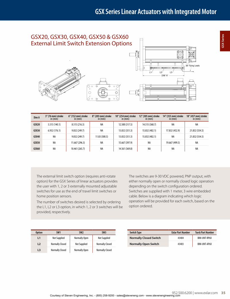
952.500.6200 | www.exlar.com 35
Option SW1 SW2 SW3 Switch Type Exlar Part Number Turck Part Number
L1 Not Supplied Normally Open Not Supplied Normally Closed Switch 43404 BIM-UNT-RP6X
L2 Normally Closed Not Supplied Normally Closed Normally Open Switch 43403 BIM-UNT-AP6X
L3 Normally Closed Normally Open Normally Closed
GSX20, GSX30, GSX40, GSX50 & GSX60 External Limit Switch Extension Options
Dim A 3" (76 mm) strokein (mm)
6" (152 mm) strokein (mm)
8" (203 mm) strokein (mm)
10" (254 mm) strokein (mm)
12" (305 mm) strokein (mm)
14" (355 mm) strokein (mm)
18" (457 mm) strokein (mm)
GSX20 5.515 (140.1) 8.515 (216.3) NA 12.500 (317.5) 14.515 (368.7) NA NA
GSX30 6.932 (176.1) 9.832 (249.7) NA 13.832 (351.3) 15.832 (402.1) 17.832 (452.9) 21.832 (554.5)
GSX40 NA 9.832 (249.7) 11.83 (300.5) 13.832 (351.3) 15.832 (402.1) NA 21.832 (554.5)
GSX50 NA 11.667 (296.3) NA 15.667 (397.9) NA 19.667 (499.5) NA
GSX60 NA 10.461 (265.7) NA 14.561 (369.8) NA NA NA
The external limit switch option (requires anti-rotate option) for the GSX Series of linear actuators provides the user with 1, 2 or 3 externally mounted adjustable switches for use as the end of travel limit switches or home position sensors.
The number of switches desired is selected by ordering the L1, L2 or L3 option, in which 1, 2 or 3 switches will be provided, respectively.
The switches are 9-30 VDC powered, PNP output, with either normally open or normally closed logic operation depending on the switch configuration ordered. Switches are supplied with 1 meter, 3 wire embedded cable. Below is a diagram indicating which logic operation will be provided for each switch, based on the option ordered.
DIM "A"
36" Flying Leads
L1 L2 L3
GSX Series Linear Actuators with Integrated Motor
GSX
Ser
ies
Courtesy of Steven Engineering, Inc. - (800) 258-9200 - [email protected] - www.stevenengineering.com

36 952.500.6200 | www.exlar.com
Actuator Rod End Options
D
A
H
FG
øB
C
J K
E
AA
A
B
øA
C
D
F
E
D DE
øF
C
B
A
øG
HøJ
K
C CB
A
øE
øD
A
A
øC
øC
D
D
øE
øE
B
B
MaleThread
MaleThread
B
B
D
D
øE
øE
F
F
øC
øC
FemaleThread
FemaleThread
*A Dim = 40mm
Standard Rod EndA B øC D øE F Male U.S. Male Metric Female U.S. Female Metric
GSX20in (mm) 0.813 (20.7) 0.375 (9.5) 0.500 (12.7) 0.200 (5.1) 0.440 (11.2) 0.750 (19.1) 3⁄8 – 24 UNF – 2A M8 x 1 6g 5/16 – 24 UNF – 2B M8 x 1 6h
GSX30 0.500 (12.7) 0.625 (15.9) 0.281 (7.1) 0.562 (14.3) 0.750 (19.1) 7/16 – 20 UNF– 2A M12 x 1.75 6g 7/16 – 20 UNF – 2B M10 x 1.5 6h
GSX40in (mm) 1.500 (38.1) 0.750 (19.1) 1.000 (25.4) 0.381 (9.7) 0.875 (22.2) 1.000 (25.4) 3⁄4 – 16 UNF – 2A M16 x 1.5 6g 5/8 – 18 UNF – 2B M16 x 1.5 6h
GSX50in (mm) 1.625 (41.3) 1.125 (28.6) 1.375 (34.9) 0.750 (19.1) 1.250 (31.8) 1.750 (44.5) 1 – 14 UNS – 2A M27 x 2 6g 1 – 14 UNS – 2B M24 x 2 6h
GSX60in (mm) 2.500 (63.5) 1.250 (31.8) 1.750 (44.5) 0.550 (14.0) 1.625 (41.3) 1.750 (44.5) 1 1/4 – 12 UNF – 2A M30 x 2 6g 7/8 – 14 UNF – 2B M25 x 1.5 6h
Drawings subject to change. Consult Exlar for certified drawings.
Part numbers for rod attachment options indicate the through hole size or pin diameter. Before selecting a spherical rod eye for use with a GSX series actuator, please consult the information on the anti-rotation option for the GSX actuators. Spherical rod eyes will allow the rod to rotate if the load is not held.
Rod End With Splined Main RodA B C D E F Male U.S. Male Metric Female U.S. Female Metric
GSX20in (mm) 0.813 (20.7) 0.375 (9.5) 0.512 (13.0) 0.200 (5.1) 0.440 (11.2) 0.750 (19.1) 3⁄8 – 24 UNF – 2A M8 x 1 6g 5/16 – 24 UNF – 2B M8 x 1 6h
GSX30 0.500 (12.7) 0.630 (16.0) 0.281 (7.1) 0.562 (14.3) 0.750 (19.1) 7/16 – 20 UNF– 2A M12 x 1.75* 6g 7/16 – 20 UNF – 2B M10 x 1.5 6h
GSX40in (mm) 1.500 (38.1) 0.750 (19.1) 0.906 (23.0) 0.381 (9.7) 0.875 (22.2) 1.000 (25.4) 3⁄4 – 16 UNF – 2A M16 x 1.5 6g 5/8 – 18 UNF – 2B M16 x 1.5 6h
GSX50in (mm) 1.625 (41.3) 1.000** (25.4) 1.102 (28.0) 0.750***
(19.1) 1.102 (28.0) 1.500 (38.1) 1 – 14 UNS – 2A M24 x 2 6g 3/4 – 16 UNF – 2B M20 x 1.5 6h
GSX60in (mm) 2.500 (63.5) 1.250 (31.8) 1.850 (47.0) 0.550 (14.0) 1.625 (41.3) 1.750 (44.5) 1 1/4 – 12 UNF – 2A M30 x 2 6g 7/8 – 14 UNF – 2B M25 x 1.5 6h
**When Male, Metric (A) = 0.945 (24 mm)***When Male (M or A) = 0.500 (12.7 mm)
GSX Series Linear Actuators with Integrated Motor
0.750* (19.1)in (mm)
0.750* (19.1)in (mm)
*When Male, Metric (A) = 1.575 (40 mm)
Courtesy of Steven Engineering, Inc. - (800) 258-9200 - [email protected] - www.stevenengineering.com

952.500.6200 | www.exlar.com 37
D DE
øF
C
B
A
øG
H øJ
K
Rod Clevis Dimensions
A øB C D E F G H J K
GSX20 SRM038in (mm) 1.625 (41.3) .375 (9.525) .906 (23.0) 1.0 (25.6) 12 deg .406 (10.3) .500 (12.7) .688 (17.7) .562 (14.3) 3/8-24
GSX30 SRM044in (mm) 1.81 (46.0 ) 0.438 (11.13) 1.06 (26.9 ) 1.13 (28.7) 14 deg 0.44 (11.1) 0.56 (14.2) 0.75 (19.1) 0.63 (16.0) 7/16-20
GSX40 SRM075in (mm)
2.88 (73.2 ) 0.75 (19.1) 1.72 (43.7) 1.75 (44.5) 14 deg 0.69 (17.5) 0.88 (22.3) 1.13 (28.7) 1.00 (25.4) 3/4-16
GSX50 SRF100in (mm) See GSX50 Special Rod Eye drawing to the right above. Requires female rod end.
A B C D E øF øG H øJ K
GSX20 RC038in (mm) 0.810 (20.6) 0.785 (19.9) 1.595 (40.5) 0.182 (4.6) 0.386 (9.8) 0.373 (9.5) 0.951 (24.2) NA NA 3/8-24
GSX30 RC050in (mm) 0.75 (19.1) 0.75 (19.1) 1.50 (38.1) 0.50 (12.7) 0.765 (19.43) 0.50 (12.7) 1.00 (25.4) 1.00 (25.4) 1.00 (25.4) 7/16-20
GSX40 RC075in (mm) 1.125 (28.58) 1.25 (31.75) 2.375 (60.3) 0.625 (15.88) 1.265 (32.13) 0.75 (19.1) 1.50 (38.1) 1.25 (31.75) 1.25 (31.75) 3/4-16
GSX50 RC100in (mm) 1.625 (41.2) 1.500 (38.1) 3.125 (79.4) 0.750 (19.1) 1.515 (38.5) 1.000 (25.4) 2.000 (50.8) 1.500 (38.1) 1.500 (38.1) 1-14
GSX60 RC138in (mm) 2.00 (50.8) 2.125 (53.98) 4.125 (104.78) 1.00 (25.4) 2.032 (51.6) 1.375 (34.93) 2.75 (69.85) 2.00 (50.8) 2.00 (50.8) 1-1/4 - 12
Drawings subject to change. Consult Exlar for certified drawings.
D
A
H
FG
øB
C
J K
E
Ø1"R1 3/8"
R1 7/16"1 1/2"
1 7/8"
1"-14Thread
LUBE FITTING
7/8"
1 1/2"
Dimensions for RE050, RC075, RC100, RC138
B
E
J
0.957
A
D
0.750
Ø F
C K
Dimensions for RC038
Spherical Rod Eye Dimensions
GSX Series Linear Actuators with Integrated Motor
GSX
Ser
ies
Courtesy of Steven Engineering, Inc. - (800) 258-9200 - [email protected] - www.stevenengineering.com

38 952.500.6200 | www.exlar.com
Rod Eye Dimensions
Clevis Pin Dimensions
øA B C D E F
GSX20 RE038in (mm) 0.50 (12.7) 0.560 (14.2) 1.000 (25.4) 0.500 (12.7) 0.25 x 45˚ 3/8 - 24
GSX30 RE050in (mm) 0.50 (12.7) 0.75 (19.1) 1.50 (38.1) 0.75 (19.1) 0.63 (15.9) 7/16 - 20
GSX40 RE075in (mm) 0.75 (19.1) 1.25 (31.8) 2.06 (52.3) 1.13 (28.7) 0.88 (22.3) 3/4 - 16
GSX50 RE100in (mm) 1.00 (25.4) 1.50 (38.1) 2.81 (71.4) 1.63 (41.4) 1.19 (30.2) 1 - 14
GSX60 RE138in (mm) 1.375 (34.93) 2.0 (50.8) 3.44 (87.3) 2.0 (50.8) 1.837 (46.67) 1 1/4 - 12
A B C øD øE
CP0501 in (mm) 2.28 (57.9) 1.94 (49.28) 0.17 (4.32) 0.50" -0.001/-0.002 (12.7 mm +0.00/-0.05) 0.106 (2.69)
CP0752 in (mm) 3.09 (78.5) 2.72 (69.1) 0.19 (4.82) 0.75" -0.001/-0.002 (19.1 mm +0.00/-0.05) 0.14 (3.56)
CP1003 in (mm) 3.59 (91.2) 3.22 (81.8) 0.19 (4.82) 1.00" -0.001/-0.002 (25.4 mm +0.00/-0.05) 0.14 (3.56)
CP1384 in (mm) 4.66 (118.3) 4.25 (108) 0.20 (5.08) 1.375" -0.001/-0.002 (34.93 mm +0.00/-0.05) 0.173 (4.39)
CP1755 in (mm) 5.656 143.6) 5.25 (133.3) 0.203 (5.15) 1.750" -0.001/-0.002 (4.44 mm +0.00/-0.05) 0.173 (4.39)1 Fits GSX20 and GSX30 rear clevis, RC050 and RE0502 Fits GSX30, 40 and RC075, RE075 and SMR0753 Fits GSX50 rear clevis, RC100, RE1004 Fits RC138, RE1385 Fits GSX60 rear clevis
Drawings subject to change. Consult Exlar for certified drawings.
AA
A
B
øA
C
D
F
E
C CB
A
øE
øD
GSX Series Linear Actuators with Integrated Motor
Courtesy of Steven Engineering, Inc. - (800) 258-9200 - [email protected] - www.stevenengineering.com

952.500.6200 | www.exlar.com 39
Notes
GSX
Ser
ies
Courtesy of Steven Engineering, Inc. - (800) 258-9200 - [email protected] - www.stevenengineering.com

40 952.500.6200 | www.exlar.com
GSX Series Ordering Information
AA = GSX Actuator Frame Size (Nominal)20 = 2 in (60 mm) 30 = 3 in (80 mm) 40 = 4 in (100 mm)50 = 5.5 in (140 mm)60 = 7 in (180 mm)
BB = Stroke Length03 = 3 in (76 mm) GSX20, GSX3004 = 4 in (102 mm) GSX40 06 = 5.9 in (150 mm) GSX30
6 in (152 mm) GSX20, GSX40, GSX50, GSX60
08 = 8 in (203 mm) GSX4010 = 10 in (254 mm) all models12 = 12 in (305 mm) GSX20, GSX30,
GSX4014 = 14 in (356 mm) GSX30, GSX5018 = 18 in (457 mm) GSX30, GSX40
CC = Lead01 = 0.1 in (2.54 mm) (GSX20, GSX30,
GSX40, GSX50)12
02 = 0.2 in (5.08 mm) (GSX20, GSX30, GSX40, GSX50)
03 = 0.25 in (6.35 mm) (GSX60)04 = 0.4 in (10.16 mm) (GSX20 only)05 = 0.5 in (12.7 mm) (GSX30, GSX40,
GSX50, GSX60)08 = 0.75 in (19.05 mm) (GSX40)8
10 = 1.0 in (25.4 mm) (GSX50, GSX60)9
D = ConnectionsI = Exlar standard M23 style10 M = Manufacturer’s connector6
A = MS style (anodized)D = MS style (electroless nickel) B = Embedded leads 3 ft. std.P = Embedded leads w/ “A” plug
3 ft. standardJ = Embedded leads w/ “I” plug,
3 ft. standardX = Special (please specify)
E = MountingB = Front and rear flangeC = Rear clevisF = Front flangeR = Rear flangeS = Side mountD = Double side mount22
T = Side trunnionE = Extended tie rodsJ = Metric side mountK = Metric double side mount22
Q = Metric side trunnionM = Metric extended tie rodsG = Metric rear clevisX = Special (please specify)
F = Rod End Thread/Rod MaterialM = Male, US std. threadA = Male, metric threadF = Female, US std. threadB = Female, metric threadW = Male, US std. thread SS21
R = Male, metric thread SS21
V = Female, US std. thread SS21
L = Female, metric thread SS21 X = Special (please specify)
GGG = Feedback Type (Also specify the Amplifier/Drive Model being used when ordering)- Standard Incremental Encoder – 2048 line
(8192 cts) per rev. index pulse, Hall commutation, 5vdc
- Standard Resolver – Size 15, 1024 line (2048 cts) per rev. two pole resolver
- Motor files for use with select Emerson/CT, Rockwell /AB and Danaher/Kollmorgen Drives are available at www.exlar.com
Custom Feedback - contact your local sales representative:XX1 = Wiring and feedback device information
must be provided and new feedback callout will be created
Allen-Bradley/Rockwell: (Note: AB8, AB9 and ABB callouts are available only on spare/replacement actuators that have been previously ordered. For all new configurations using a Rockwell drive, please select from the options below. Consult Exlar for integration questions)RA1 = Hiperface Stegmann SKM36 multi-turn
absolute encoder. MPL Type V feedback (128 sin/cos) and Type 7 SpeedTec connectors and wiring when using the “M” connector option. 20 and 30 frame sizes only. (Formerly ABB)16
RA2 = Hiperface Stegmann SRM50 multi-turn absolute encoder. MPL Type M feedback (1024 sin/cos) and Type 7 SpeedTec connectors and wiring when using the “M” connector option. 40, 50 and 60 frame sizes only. (Formerly AB9)16
RA3 = Standard incremental encoder. MPL Type M feedback (2048 line) and Type 7 SpeedTec connector and wiring when using the “M” connector option. (Formerly AB8)
RA4 = Standard Resolver. MPL Type R feedback (4 pole) and Type 7 SpeedTec connectors and wiring when using the “M” connector option. (Formerly AB6)
AMKASYN:AK1 = EnDat Heidenhain EQN1325 multi-turn
absolute encoder – 40-50-60 Frame Size. DS motor wiring w/M23 euro connectors for ‘M’ option
AK2 = EnDat Heidenhain EQN1125 multi-turn absolute encoder – 20-30 Frame Size. DS motor wiring w/M23 euro connectors for ‘M’ option
Advanced Motion Control:AM1 = Standard Incremental Encoder AM2 = Encoder 1000 line, w/commutation, 5 VDCAM3 = Standard ResolverAM5 = Encoder 5000 line, w/commutation, 5 VDCAPI Controls:AP1 = Standard ResolverAP2 = Standard Incremental Encoder Aerotech:AR1 = Encoder 5000 line, w/commutation, 5 VDCAR2 = Standard Incremental EncoderBaldor:BD2 = Std Resolver – BSM motor wiring w/M23
connectors for ‘M’ option BD3 = Std Incremental Encoder – BSM motor
wiring w/M23 connectors for ‘M’ option
Beckhoff:BE2 = EnDat Heidenhain EQN1125 multi-turn
absolute encoder – AM5XX motor wiring w/M23 euro connectors for ‘M’ option
Baumueller:BM2 = Standard ResolverB&R Automation:BR1 = Standard ResolverBR2 = EnDat Heidenhain EQN1125/1325
multi-turn absolute encoder – 8LS/8LM motor wiring w/M23 euro connectors for ‘M’ option
Copley Controls:CO1 = Standard Incremental EncoderCO2 = Standard ResolverControl Techniques/Emerson:CT1 = Hiperface Stegmann SRM050 multi-turn
absolute encoder – 40-50-60 Frame Size. FM/UM/EZ motor wiring w/M23 euro connectors for ‘M’ option
CT3 = Hiperface Stegmann SKM036 multi-turn absolute encoder – 20-30 Frame Size. FM/UM/EZ motor wiring w/M23 euro connectors for ‘M’ option
CT4 = Standard Incremental Encoder – FM/UM/EZ motor wiring w/M23 euro connectors for ‘M’ option
CT5 = Std Resolver – FM/UM/EZ motor wiring w/M23 euro connectors for ‘M’ option
CT7 = Encoder 5000 line, with commutation, 5 VDC – FM/UM/EZ motor wiring w/M23 euro connectors for ‘M’ option
Delta Tau Data Systems:DT1 = Encoder 1000 line, with commutation,
5 VDCDT2 = Standard ResolverElmo Motion Control:EL1 = Standard ResolverEL2 = Standard Incremental EncoderEL3 = EnDat Heidenhain EQN1125 multi-turn
absolute encoderEmerson/Control Techniques:EM2 = Std Incremental Encoder – NT motor
wiring w/MS connectors for ‘M’ optionEM5 = Encoder 5000 line, with commutation,
5 VDC – NT motor wiring w/MS connectors for ‘M’ option
Elau:EU1 = Hiperface Stegmann SRM050 multi-turn
absolute encoder – 40-50-60 Frame Size. SH motor wiring w/MS connectors for ‘M’ option
EU4 = Hiperface Stegmann SKM036 multi-turn absolute encoder – 20-30 Frame Size. SH motor wiring w/MS connectors for ‘M’ option
Exlar:EX4 = Standard ResolverEX5 = Standard Resolver with KTY84 thermistorEX6 = EnDat Heidenhain EQN/125 multi-turn
absolute encoder EX7 = Incremental encoder, 5000 line with
commutation, 5Vdc EX8 = Hiperface Stegmann SRM50 multi-turn
absolute encoderG&L Motion Control/Danaher Motion:GL1 = Std Incremental Encoder – HSM motor
wiring w/ MS connectors for ‘M’ optionGL2 = Std Incremental Encoder – LSM-MSM
motor wiring w/M23 euro connectors for ‘M’ option
GSXAA - BBCC - DEF - GGG - HHH - II - (XX..XX)
For cables and accessories see page 116.40 952.500.6200 | www.exlar.comCourtesy of Steven Engineering, Inc. - (800) 258-9200 - [email protected] - www.stevenengineering.com

952.500.6200 | www.exlar.com 41
GSX Series Ordering Information
GL3 = Std Incremental Encoder – NSM motor wiring w/MS connectors for ‘M’ option
GL4 = EnDat Heidenhain EQN1125 multi-turn absolute encoder – AKM motor wiring w/M23 euro connectors for ‘M’ option
Infranor:IF1 = Standard ResolverIndramat/Bosch-Rexroth:IN6 = Std Resolver – MKD/MHD motor wiring
w/M23 euro connectors for ‘M’ optionIN7 = Hiperface Stegmann SKM036 multi-turn
absolute encoder – MSK motor wiring w/M23 euro connectors for ‘M’ option – plug & play option
Jetter Technologies:JT1 = Standard Resolver – JH/JL motor wiring
w/M23 euro connectors for ‘M’ optionKollmorgen/Danaher:KM4 = EnDat Heidenhain EQN1325 multi-turn
absolute encoder – AKM motor wiring w/M23 euro connectors for ‘M’ option
KM5 = Standard Resolver – AKM motor wiring w/M23 euro connectors for ‘M’ option
KM6 = Standard Incremental Encoder – AKM motor wiring w/ M23 euro connectors for ‘M’ option
Lenze/AC Tech: LZ1 = Hiperface Stegmann SRM050 multi-turn
absolute encoder – MCS motor wiring w/M23 euro connectors for ‘M’ option
LZ5 = Standard Resolver – MCS motor wiring w/ M23 euro connectors for ‘M’ option
LZ6 = Standard Incremental Encoder – MCS motor wiring w/ M23 euro connectors for ‘M’ option
Metronix:MX1 = Standard Resolver N/A with Clevis, GSX/
GSM onlyMX2 = Hiperface Stegmann SKM036 multi-turn
absolute encoderMX3 = EnDat Heidenhain EQN1125 multi-turn
absolute encoderMitsubishi20:MT1 = Mitsubishi Absolute Encoder – HF-SP motor
wiring with ‘M’ option (N/A with clevis)Momentum:MN1 = Hyperface Stegmann SRM050 multi-turn
absolute encoder – MN motor wiring w/M23 connectors for ‘M’ option
MN2 = EnDat Heidenhain EQN1325 multi-turn absolute encoder – MN motor wiring connectors for ‘M’ option
MN3 = Std incremental encoder – MN motor wiring w/M23 connectors for ‘M’ option
MN4 = Std resolver – MN motor wiring w/M23 connectors for ‘M’ option
Moog:MG1 = Standard ResolverOrmec:OR1 = Standard Resolver OR2 = Std Incremental Encoder – G series motor
wiring w/ MS connectors for ‘M’ optionParker Compumotor:PC6 = Std Incremental Encoder – SMH motor
wiring w/M23 connectors for ‘M’ option – European only
PC7 = Std Resolver – SMH motor wiring w/M23 connectors for ‘M’ option – European only
PC8 = Standard Incremental Encoder – MPP series motor wiring w/PS connectors for ‘M’ option – US Only
PC9 = Hiperface Stegmann SRM050 multi-turn absolute encoder – MPP motor wiring w/PS connectors for ‘M’ option – US Only
PC0 = Standard Resolver – MPP motor wiring w/PS connectors for ‘M’ option – US Only
Pacific Scientific:PS2 = Standard Incremental EncoderPS3 = Standard Resolver – PMA motor wiring
w/M23 connectors for ‘M’ optionStober Drives:SB2 = Standard Resolver ED/EK motor wiring
w/M23 connector for ‘M’ optionSB3 = EnDat Heidenhain EQN1125 multi-turn
absolute encoder – ED/EK motor wiring w/M23 euro connectors for ‘M’ option
Siemens:SM2 = Standard Resolver – 1FK7 motor wiring
w/M23 connectors for ‘M’ optionSM3 = EnDat Heidenhain EQN1325 multi-turn
absolute encoder – 40-50-60 Frame Size. 1FK7 motor wiring w/M23 euro connectors for ‘M’ option
SM4 = EnDat Heidenhain EQN1125 multi-turn absolute encoder – 20-30 Frame Size. 1FK7 motor wiring w/M23 euro connectors for ‘M’ option
SEW/Eurodrive:SW1 = Standard Resolver – CM motor wiring
w/ M23 euro connectors for ‘M’ optionSW2 = Standard Incremental EncoderSW3 = Hiperface Stegmann SRM050 multi-turn
absolute encoder – CM motor wiring w/ M23 euro connectors for ‘M’ option
Yaskawa:YS2 = Yaskawa Absolute Encoder – SGMGH
motor wiring 40, 50, 60 Exlar Frame SizesYS3 = Yaskawa Absolute Encoder – SGMGH
motor wiring 20/30 Exlar Frame Sizes
HHH = Motor Stator – 8 Pole2 Class 180H19
II = Motor Speed24 = 2400 rpm, GSX50, GSX60 30 = 3000 rpm, GSX30, GSX4050 = 5000 rpm, GSX2001- 99 = Customer specified base speed
XX .. XX = Options
Travel OptionsPF = Preloaded follower1
AR = External anti-rotate assembly18
RB = Rear electric brake4
RD = Manual drive, Simple Rear13, 20
SD = Manual drive, Side Hex20
HW = Manual drive, Handwheel with interlock switch14, 20
PB = Protective bellows15
SR = Splined main rod11, 21
XT = Special travel option (see pg. 27), high temp bellows15
L1/L2/L3 = External limit switches7
Motor OptionsXM = Special motor optionXL = Special lubrication food grade or
Mobilgrease 28 or use of oil cooling, specify (see page 27)
118 = 1 stack115
Vrms
158 = 1 stack400
Vrms218 = 2 stack 258 = 2 stack318 = 3 stack 358 = 3 stack138 = 1 stack
230 Vrms
168 = 1 stack460
Vrms238 = 2 stack 268 = 2 stack338 = 3 stack 368 = 3 stack
Housing OptionsFG = White epoxy5 EN = Electroless nickel plating5
HC = Type III hard coat anodized, class I5 SS = Stainless steel housing5, 17 XH = Special housing option
Absolute Linear FeedbackLT = ICT, including signal conditioner3
##### = Part No. Designator for Specials Optional 5 digit assigned part number to designate unique model numbers for specials. 1. The dynamic load rating of zero backlash, preloaded
screws is 63% of the dynamic load rating of the standard non-preloaded screws. The calculated travel life of a preloaded screw will be 25% of the calculated travel life of the same size and lead of a non-preloaded screw. Preloaded follower is not available with absolute linear (LT) internal feedback option.
2. Stator voltage and pole options allow for catalog rated performance at varying amplifier bus voltages and pole configuration requirements. Refer to perfomance specification on pages 11-13 for availability of 3 stack stator.
3. Linear feedback is not available in the GSX20 and not available with absolute feedback. Not available with PF, not available with any stroke 14" or greater or with Yaskawa.
4. The brake option may require a third cable, consult local sales representative.
5. These housing options would typically be accompanied by the choice of the electroless nickel connectors if a connectorized unit were selected. This choice may also indicate the need for special material main rods or mounting.
6. Available as described in Feedback Types.
7. Requires AR option.
8. 0.75 lead not available above 12".
9. 1.0 lead not available above 10" stroke.
10. GSX60 uses M40 size 1.5 power connector.
11. If not otherwise specified by the customer, an M24x2 male rod end will be used on the GSX50. See note on page 26.
12. 0.1 lead not available over 10" stroke on GSX50.
13. Not available with absolute feedback, absolute linear feedback, rear clevis or rear flange.
14. Not available on GSX20.
15. N/A with extended tie rod mounting option.
16. Not compatible with Kinetix 300 Drives.
17. Force, torque and current ratings are reduced 25% with this option.
18. A second anti-rotate arm is used on GSX20, 30 & 40 for 10" and longer stroke.
19. See page 28 for optimized stator offerings.
20. N/A with holding brake unless application details are discussed with your local sales representative.
21. Consult your local sales representative if ordering splined stainless steel main rod.
22. Anti-rotate with D or K mount N/A on 10" or longer stroke except in GSX50.
952.500.6200 | www.exlar.com 41
GSX
Ser
ies
Courtesy of Steven Engineering, Inc. - (800) 258-9200 - [email protected] - www.stevenengineering.com

42 952.500.6200 | www.exlar.com
GSM Series–Standard Capacity Roller Screw OptionThis design incorporates Exlar’s patented roller screw technology with an integral brushless servo motor for medium to high performance motion control applications. The GSM Series offers 5 times the travel life of similarly sized ball screw actuators. It also provides a smaller package with higher speed and higher load capacity than ball screws and other traditional rotary to linear conversion mechanisms. These features make the GSM Series an excellent replacement for ball screw actuators.
Selection of the proper feedback configuration allows GSM Series actuators to be powered by nearly every brand of brushless motor amplifier on the market. This flexibility allows GSM Series actuators to be incorporated into the highest performance single and multi-axis motion control systems in use today. In applications varying from food and beverage packaging, to multi-axis turning centers, to aircraft assembly, the GSM Series of actuators show incredible performance and durability.
Exlar’s T-LAM technology incorporated into the motor design provides a solution with 35% more torque in the same package size as traditional brushless motors. The efficiencies of the GSM Series are a result of the limited heat generation qualities inherent in the segmented stator design. The elimination of end turns in the stator, and the use of thermally conductive potting removes the parts most susceptible to failure in a traditional stator. Other benefits include:
• Neodymium iron boron magnets provide high flux density and maximum motor torque.
• Thermally conductive potting of the entire stator provides increased heat dissipation and provides protection.
• Each stator segment contains individual phase wiring. External winding of individual segments provides maximum slot fill for maximum motor performance.
• Motors with T-LAM technology have Class H insulation systems compliant with UL requirements.
Features/Characteristics
T-LAM™ segmented lamination stator technology
2.25, 3.3 or 3.9 inch (60, 80 or100 mm) frame size
3, 4, 5.9, 6, 10 ,12, 14 and18 inch (76, 102, 152, 156, 203, 254, 305 and 356 mm) strokes
0.1, 0.2, 0.4, 0.5 and .75 inch (2.54, 5.08, 10.16, 12.7 and 19.05 mm) lead roller screws
7 to 75 lbf-in (0.8 to 8.47 Nm) torque motor availability
Up to 33 inch (838.2 mm) per second linear speeds
92 to 1983 lbf (409 to 8821 N) thrust capacity depending on motor selection
Front flange, rear flange, rear clevis, trunnion, side, double side or extended tie rods mounting options
Encoder feedback with MS style connectors
Molded and shielded cables available
Anodized aluminum housing
Competitively priced with ball screw actuators
5 times the life of a similar sized ball screw actuator
IP54S or IP65S sealing
Class 180 H insulation
UL recognized component
Lamination Endcaps
Individual Segments
GSM Series Linear Actuators with Integrated Motor
42 952.500.6200 | www.exlar.comCourtesy of Steven Engineering, Inc. - (800) 258-9200 - [email protected] - www.stevenengineering.com

952.500.6200 | www.exlar.com 43
Hydraulic cylinder replacementBall screw replacementPneumatic cylinder replacementChip and wafer handlingAutomated flexible fixturingDispensersMachine toolAutomated assemblyParts clampingAutomatic tool changersVolumetric pumps
Medical equipmentConveyor diverters / gatesPlastics equipmentCut-offsDie cuttersPackaging machineryEntertainmentSawmill equipmentOpen / close doorsFillersFormersPrecision grindersIndexing stages
LiftsProduct sortingMaterial cuttingMaterial handlingRiveting / fastening / joiningMoldingVolumetric pumpsSemiconductorPick and place systemsRobot manipulator armsSimulatorsPrecision valve control
Ventilation control systemsPressingProcess controlTube bendingWeldingStampingTest standsTension controlWeb guidanceWire windingFood ProcessingDampers
Exlar GSM Series Linear Actuators Applications Include:
GSM-Series actuators can provide the precision at high force loads for fluid dispensing in a medical environment.
A typical 3 inch stroke GSM Series actuator used in a valve-modulating application can control position to +/– .5% while ready to fully open or close in less than 200 mSec.
All-electric replacement for hydraulic cylinders improves throughput with servo control and less maintenance for core-pull cylinders.
GSM Series Linear Actuators with Integrated Motor
GSM
Ser
ies
Courtesy of Steven Engineering, Inc. - (800) 258-9200 - [email protected] - www.stevenengineering.com

44 952.500.6200 | www.exlar.com
GSM Series Performance
Test data derived using NEMA recommended aluminum heatsink 10" x 10" x 1/4"on GSM20 and 10" x 10" x 3/8" on GSM30
The below speed vs. force curves represent approximate continuous thrust ratings at indicated linear speed. Different types of servo amplifiers will offer varying motor
torque and thus actuator thrust. These values are at constant velocity and do not account for motor torque required for acceleration.
Speed in/sec (mm/sec)
Speed in/sec (mm/sec)
Speed in/sec (mm/sec)
Forc
e lb
f (N
m)
Forc
e lb
f (N
m)
Forc
e lb
f (N
m)
GSM20-.1 Inch Lead
GSM20-.2 Inch Lead
GSM20-.4 Inch Lead
700 (3114)
600 (2670)
500 (2224)
400 (1779)
300 (1334)
200 (890)
100 (445)
0
350 (1557)
300 (1334)
250 (1112)
200 (890)
150 (667)
100 (445)
50 (222)
0
180 (801)
160 (712)
140 (623)
120 (534)
100 (445)
80 (356)
60 (267)
40 (178)
20 (89)
0
GSM20-.1 Inch Lead
1 Stack2 Stack
GSM20-.2 Inch Lead
1 Stack2 Stack
GSM20-.4 Inch Lead
1 Stack2 Stack
0 1 2 3 4 5 6 7 8 9 (25.4) (50.8) (76.2) (101.6) (127) (152.4) (177.8) (203.2) (228.6)
0 2 4 6 8 10 12 14 16 18 (50.8) (101.6) (152.4) (203.2) (254) (304.8) (355.6) (406.4) (457.2)
0 5 10 15 20 25 30 35 (127) (254) (381) (508) (635) (762) (889)
Speed in/sec (mm/sec)
Speed in/sec (mm/sec)
Speed in/sec (mm/sec)
Forc
e lb
f (N
m)
Forc
e lb
f (N
m)
Forc
e lb
f (N
m)
GSM30-.1 Inch Lead
GSM30-.2 Inch Lead
GSM30-.5 Inch Lead
1400 (6228)
1200 (5338)
1000 (4448)
800 (3559)
600 (2670)
400 (1779)
200 (890)
0
800 (3559)
700 (3114)
600 (2670)
500 (2224)
400 (1779)
300 (1334)
200 (890)
100 (445)
0
300 (1557)
300 (1334)
250 (1112)
200 (895)
150 (667)
100 (445)
50 (222)
0
GSM30-.1 Inch Lead
1 Stack2 Stack
GSM30-.2 Inch Lead
1 Stack2 Stack
GSM30-.5 Inch Lead
1 Stack2 Stack
0 1 2 3 4 5 6 (25.4) (50.8) (76.2) (101.6) (127) (152.4)
0 2 4 6 8 10 12 (50.8) (101.6) (152.4) (203.2) (254) (304.8)
0 5 10 15 20 25 30 (127) (254) (381) (508) (635) (762)
GSM Series Linear Actuators with Integrated Motor
Courtesy of Steven Engineering, Inc. - (800) 258-9200 - [email protected] - www.stevenengineering.com

952.500.6200 | www.exlar.com 45
Life Curves Estimated L10 Travel Life
Test data derived using NEMA recommended aluminum heatsink 12" x 12" x 1/2" on GSM40
See page 10 for Life Curve Information. If your application requires high force over a stroke length shorter than the length of the nut, please contact Exlar for derated life calculations. You may also download the article “Calculating Life Expectency” at www.exlar.com/technical_reference_notes
Speed in/sec (mm/sec)
Forc
e lb
f (N
m)
GSM40-.75 Inch Lead700
(3114)
600 (2670)
500 (2224)
400 (1779)
300 (1334)
200 (890)
100 (445)
0
GSM40-.75 Inch Lead
1 Stack2 Stack
0 5 10 15 20 25 30 35 40 (127) (254) (381) (508) (635) (762) (859) (1016)
GSM20 GSM30 GSM40
Travel Life Millions of inches (mm) Travel Life Millions of inches (mm) Travel Life Millions of inches (mm)
Cub
ic M
ean
Load
lbf (
N)
Cub
ic M
ean
Load
lbf (
N)
Cub
ic M
ean
Load
lbf (
N)
800 (3559)
700 (3114)
600 (2669)
500 (2224)
400 (1779)
300 (1334)
200 (890)
100 (445)
0 1 10 100 1,000 10,000 (25.4) (254) (2,540) (25,400) (254,000)
1 10 100 1,000 10,000 (25.4) (254) (2,540) (25,400) (254,000)
1 10 100 1,000 10,000 (25.4) (254) (2,540) (25,400) (254,000)
Speed in/sec (mm/sec)
Forc
e lb
f (N
m)
GSM40-.5 Inch Lead1000
(4448)
800 (3559)
600 (2669)
400 (1779)
200 (890)
0
GSM40-.5 Inch Lead
1 Stack2 Stack
0 5 10 15 20 25 30 (127) (254) (381) (508) (635) (762)
Speed in/sec (mm/sec)
Forc
e lb
f (N
m)
GSM40-.2 Inch Lead2500
(11120)
2000 (8896)
1500 (6672)
1000 (4448)
500 (2224)
0
GSM40-.2 Inch Lead
1 Stack2 Stack
0 2 4 6 8 10 12 (50.8) (101.6) (152.4) (203.2) (254) (304.8)
Speed in/sec (mm/sec)
Forc
e lb
f (N
m)
GSM40-.1 Inch Lead4000
(17793)3500
(15569)3000
(13345)2500
(11121)2000
(8896)1500
(6672)1000
(4448)500
(2224)0
GSM40-.1 Inch Lead
1 Stack2 Stack
0 1 2 3 4 5 6 (25.4) (50.8) (76.2) (101.6) (127) (152.4)
GSM Series Linear Actuators with Integrated Motor
GSM20-xx01
GSM20-xx02
GSM20-xx04
GSM30-xx01
GSM30-xx02
GSM30-xx05
GSM40-xx01
GSM40-xx02
GSM40-xx05
GSM40-xx08
3000 (13345)
2,500 (11121)
2,000 (8896)
1,500 (6672)
1,000 (4448)
500 (2224)
0
4000 (17793)
3,500 (15569)
3000 (13345)
2,500 (11121)
2,000 (8896)
1,500 (6672)
1,000 (4448)
500 (2224)
0
GSM
Ser
ies
Courtesy of Steven Engineering, Inc. - (800) 258-9200 - [email protected] - www.stevenengineering.com

46 952.500.6200 | www.exlar.com
GSM20 & GSM30 Performance Specifications
Model No.Frame Size
in (mm)Strokein (mm)
Screw Leadin (mm)
Continuous Force Rating
lb (N)1 stack/2 stack
Max Velocityin/sec
(mm/sec)
Maximum Static Load
lb (N)
Armature Inertia**
lb-in-s2 (Kg-m2)
Dynamic Load Ratinglb (N)
Weight (approx.)
lb (kg)
GSM20-0301
2.25(57)
3(76)
0.1 (2.54)
367/578(1,632/2,571)
8.33 (211.67)
750(3336)
0.00101(0.000114)
1568(6970)
6.5 (2.9)GSM20-0302 0.2
(5.08)195/307
(867/1,366)16.77
(423.33)1219
(5422)
GSM20-0304 0.4(10.16)
103/163(459/723)
33.33 (846.67)
738(3283)
GSM20-0601
2.25 (57)
6 (152)
0.1(2.54)
367/578(1,632/2,571)
8.33 (211.67)
750 (3336)
0.00114(0.000129)
1567(6970)
7.0 (3.2)GSM20-0602 0.2
(5.08)195/307
(867/1,366)16.67
(423.33)1219
(5422)
GSM20-0604 0.4(10.16)
103/163(459/723)
33.33(846.67)
738(3283)
GSM20-1001
2.25 (57)
10 (254)
0.1 (2.54)
367/578(1,632/2,571)
8.33 (211.67)
750 (3336)
0.00133(0.000150)
1567(6970)
7.5 (3.4)GSM20-1002 0.2
(5.08)195/307
(867/1,366)16.67
(423.33)1219
(5422)
GSM20-1004 0.4(10.16)
103/163(459/723)
33.33(846.67)
738(3283)
GSM20-1201
2.25(57)
12(305)
0.1(2.54)
367/578(1,632/2,571)
8.33(211.67)
750 (3336)
0.00143(0.000162)
1567(6970)
8.0 (3.6)GSM20-1202 0.2
(5.08)195/307
(867/1,366)16.67
(423.33)1219
(5422)
GSM20-1204 0.4(10.16)
103/163(459/723)
33.33(846.67)
738(3283)
GSM30-0301
3.3(84)
3(76)
0.1(2.54)
792/1,277(3,521/5,680)
5(127)
1620(7206)
0.00319(0.000360)
3310(14724)
9.5(4.3)GSM30-0302 0.2
(5.08)449/724
(1,995/3,219)10
(254)3570
(15880)
GSM30-0305 0.5(12.7)
190/306(845/1,363)
25(635)
3016(13416)
GSM30-0601
3.3(84)
5.9(150)
0.1(2.54)
792/1,277(3,521/5,680)
5(127)
1620(7206)
0.00361(0.000408)
3310(14724)
11.5(5.2)GSM30-0602 0.2
(5.08)449/724
(1,995/3,219)10
(254)3570
(15880)
GSM30-0605 0.5(12.7)
190/306(845/1,363)
25(635)
3016(13416)
GSM30-1001
3.3(84)
10(254)
0.1(2.54)
792/1,277(3,521/5,680)
5(127)
1620(7206)
0.00416(0.00047)
3310(14724)
19(8.6)GSM30-1002 0.2
(5.08)449/724
(1,995/3,219)10
(254)3570
(15880)
GSM30-1005 0.5(12.7)
190/306(845/1,363)
25(635)
3016(13416)
GSM30-1201
3.3(84)
12(305)
0.1(2.54)
792/1,277(3,521/5,680)
5(127)
1620(7206)
0.00443(0.000501)
3310(14724)
20.5(9.3)GSM30-1202 0.2
(5.08)449/724
(1,995/3,219)10
(254)3570
(15880)
GSM30-1205 0.5(12.7)
190/306(845/1,363)
25(635)
3016(13416)
GSM30-1401
3.3(84)
14(356)
0.1(2.54)
792/1,277(3,521/5,680)
5(127)
1620(7206)
0.00473(0.000534)
3310(14724)
22 (10)GSM30-1402 0.2
(5.08)449/724
(1,995/3,219)10
(254)3570
(15880)
GSM30-1405 0.5(12.7)
190/306(845/1,363)
25(635)
3016(13416)
GSM30-1801
3.3(84)
18(457)
0.1(2.54)
792/1,277(3,521/5,680)
5(127)
1620(7206)
0.00533(0.000602)
3310(14724)
25 (11.3)GSM30-1802 0.2
(5.08)449/724
(1,995/3,219)10
(254)3570
(15880)
GSM30-1805 0.5(12.7)
190/306(845/1,363)
25(635)
3016(13416)
**Inertia +/– 5% See page 47 for definition of terms.
GSM Series Linear Actuators with Integrated Motor
Courtesy of Steven Engineering, Inc. - (800) 258-9200 - [email protected] - www.stevenengineering.com

952.500.6200 | www.exlar.com 47
GSM40 Performance Specifications
Model No.Frame Size
in (mm)Strokein (mm)
Screw Leadin (mm)
Continuous Force Rating
lb (N) 1 stack/2 stack
Max Velocityin/sec
(mm/sec)
Maximum Static Load
lb (N)
Armature Inertia**
lb-in-s2 (Kg-m2)
Dynamic Load Rating
lb (N)
Weight (approx.)
lb (kg)
GSM40-0401
3.9(99)
4(102)
0.1 (2.54)
2,089/NA(9,293/NA)
5(127)
3966(17642)
0.0140 (0.001582)
4736(21067)
16(7.3)
GSM40-0402 0.2(5.08)
1,194/NA(5,310/NA)
10 (254)
4890(21751)
GSM40-0405 0.5(12.7)
537/NA(2,390/NA)
25(635)
4218(18763)
GSM40-0408 0.75(19.05)
358/NA(1,593/NA)
37.5(953)
3328(14804)
GSM40-0601
3.9(99)
6(152)
0.1 (2.54)
2,089/3,457(9,293/15,377)
5(127)
3966(17642)
0.0152 (0.001717)
4736(21067)
20(9.1)
GSM40-0602 0.2(5.08)
1,194/1,975(5,310/8,787)
10 (254)
4890(21751)
GSM40-0605 0.5(12.7)
537/889(2,390/3,954)
25(635)
4218(18763)
GSM40-0608 0.75(19.05)
358/593(1,593/2,636)
37.5(953)
3328(14804)
GSM40-0801
3.9(99)
8(203)
0.1 (2.54)
2,089/3,457(9,293/15,377)
5(127)
3966(17642)
0.0163(0.001842)
4736(21067)
24(10.9)
GSM40-0802 0.2(5.08)
1,194/1,975(5,310/8,787)
10 (254)
4890(21751)
GSM40-0805 0.5(12.7)
537/889(2,390/3,954)
25(635)
4218(18763)
GSM40-0808 0.75(19.05)
358/593(1,593/2,636)
37.5(953)
3328(14804)
GSM40-1001
3.9(99)
10(254)
0.1(2.54)
2,089/3,457 (9,293/15,377)
5(127)
3966(17642)
0.0175 (0.001977)
4736(21067)
28(12.7)
GSM40-1002 0.2(5.08)
1,194/1,975(5,310/8,787)
10(254)
4890(21751)
GSM40-1005 0.5(12.7)
537/889(2,390/3,954)
25(635)
4218(18763)
GSM40-1008 0.75(19.05)
358/593(1,593/2,636)
37.5(953)
3328(14804)
GSM40-1201
3.9 (99)
12(305)
0.1(2.54)
2,089/3,457(9,293/15,377)
5(127)
3966(17642)
0.0186 (0.002102)
4736(21067)
32(14.5)
GSM40-1202 0.2(5.08)
1,194/1,975(5,310/8,787)
10(254)
4890(21751)
GSM40-1205 0.5(12.7)
537/889(2,390/3,954)
25(635)
4218(18763)
GSM40-1208 0.75(19.05)
358/593(1,593/2,636)
37.5(953)
3328(14804)
GSM40-1801
3.9 (99)
18 (457)
0.1(2.54)
2,089/3,457(9,293/15,377)
5 (127)
3966(17642)
0.0220 (0.002486)
4736(21067)
44(19.9)GSM40-1802 0.2
(5.08)1,194/1,975
(5,310/8,787)10
(254)4890
(21751)
GSM40-1805 0.5(12.7)
537/889(2,390/3,954)
25(635)
4218(18763)
**Inertia +/– 5% See below for definition of terms.
Continuous Force Rating: The linear force produced by the actuator at continuous motor torque.
Max Velocity: The linear velocity that the actuator will achieve at rated motor rpm.
Maximum Static Load: The mechanical load limit of the actuator if re-circulated oil or other cooling method is used to allow higher than rated torque from the motor.
Armature Inertia: The rotary inertia of the armature of the GSM Series actuators. For calculation purposes, this value includes the screw inertia in a GSM actuator.
Dynamic Load Rating: A design constant used in calculating the estimated travel life of the roller screw. The cubic mean load is the load at which the device will perform one million revolutions.
DEFINITION OF TERMS:
GSM Series Linear Actuators with Integrated Motor
GSM
Ser
ies
Courtesy of Steven Engineering, Inc. - (800) 258-9200 - [email protected] - www.stevenengineering.com

48 952.500.6200 | www.exlar.com
GSM20 Mechanical and Electrical SpecificationsNominal Backlash in (mm) 0.008 (0.20)
Lead Accuracy in/ft (mm/300 mm) 0.001 (0.025)
Maximum Radial Load lb (N) 15 (67)
Environmental Rating: Standard/Optional IP54S/IP65S
Motor Stator 118 138 158 168 218 238 258 268
RMS SINUSOIDAL COMMUTATION
Continuous Motor Torque lbf-in(Nm)
7.6(0.86)
7.3(0.83)
7.0(0.79)
7.0(0.79)
11.9(1.34)
11.5(1.30)
11.0(1.25)
11.3(1.28)
Torque Constant (Kt)(+/– 10% @ 25˚C)
lbf-in/A(Nm/A)
2.5(0.28)
5.2(0.59)
7.5(0.85)
9.5(1.07)
2.5(0.28)
5.2(0.59)
8.6(0.97)
10.1(1.15)
Continuous Current Rating A 3.4 1.6 1.0 0.8 5.4 2.5 1.4 1.2
Peak Current Rating A 6.9 3.1 2.1 1.6 10.8 4.9 2.9 2.5
O-PK SINUSOIDAL COMMUTATION
Continuous Motor Torque lbf-in(Nm)
7.6(0.86)
7.3(0.83)
7.0(0.79)
7.0(0.79)
11.9(1.34)
11.5(1.30)
11.0(1.25)
11.3(1.28)
Torque Constant (Kt)(+/– 10% @ 25˚C)
lbf-in/A(Nm/A)
1.7(0.20)
3.7(0.42)
5.3(0.60)
6.7(0.76)
1.7(0.20)
3.7(0.42)
6.1(0.69)
7.2(0.81)
Continuous Current Rating A 4.9 2.2 1.5 1.2 7.6 3.5 2.0 1.8
Peak Current Rating A 9.7 4.5 2.9 2.3 15.2 7.0 4.1 3.5
MOTOR STATOR DATA
Voltage Constant (Ke) Vrms/Krpm 16.9 35.5 51.5 64.8 16.9 35.5 58.6 69.3
(+/– 10% @ 25˚C) Vpk/Krpm 23.9 50.2 72.8 91.7 23.9 50.2 82.9 98.0
Pole Configuration 8 8 8 8 8 8 8 8
Resistance (L-L)(+/– 5% @ 25˚C) Ohms 2.6 12.5 28.8 45.8 1.1 5.3 15.5 20.7
Inductance (L-L)(+/– 15%) mH 4.6 21.4 47.9 68.3 2.5 10.2 28.3 39.5
Brake Inertia lbf-in-sec2 (Kg-cm2) 0.00012 (0.135)
Brake Current @ 24 VDC A 0.33
Brake Holding Torque lbf-in (Nm) 19 (2.2)
Brake Engage/Disengage Time ms 14/28
Mechanical Time Constant (tm), ms min 4.7 5.1 5.5 5.6 2.0 2.1 2.3 2.2
max 6.6 7.2 7.9 7.9 2.8 3.0 3.3 3.1
Electrical Time Constant (te) ms 1.8 1.7 1.7 1.5 2.2 1.9 1.8 1.9
Friction Torque lbf-in (Nm) 1.0 (0.12) 1.1 (0.12)
Additional Friction Torque for Preloaded Screw lbf-in (Nm) 1.25 (0.14) 1.25 (0.14)
Bus Voltage Vrms 115 230 400 460 115 230 400 460
Speed @ Bus Voltage rpm 5000
Insulation Class 180 (H)
All ratings at 25 degrees Celsius Specifications subject to change without notice.For amplifiers using peak sinusoidal ratings, multiply RMS sinusoidal Kt by 0.707 and current by 1.414.Test data derived using NEMA recommended aluminum heatsink 10" x 10" x 1/4"
GSM Series Linear Actuators with Integrated Motor
Courtesy of Steven Engineering, Inc. - (800) 258-9200 - [email protected] - www.stevenengineering.com
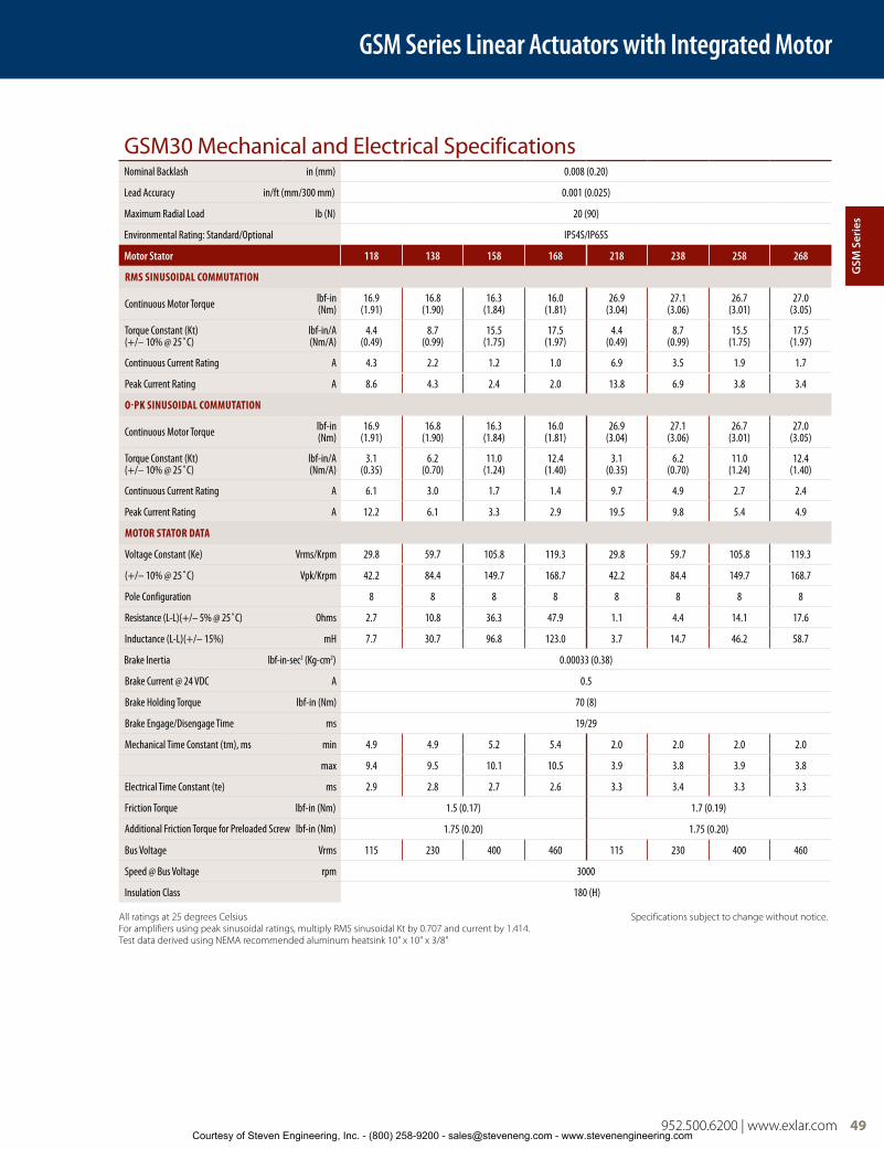
FT80 Series Linear Actuators
952.500.6200 | www.exlar.com 49
GSM30 Mechanical and Electrical SpecificationsNominal Backlash in (mm) 0.008 (0.20)
Lead Accuracy in/ft (mm/300 mm) 0.001 (0.025)
Maximum Radial Load lb (N) 20 (90)
Environmental Rating: Standard/Optional IP54S/IP65S
Motor Stator 118 138 158 168 218 238 258 268
RMS SINUSOIDAL COMMUTATION
Continuous Motor Torque lbf-in(Nm)
16.9(1.91)
16.8(1.90)
16.3(1.84)
16.0(1.81)
26.9(3.04)
27.1(3.06)
26.7(3.01)
27.0(3.05)
Torque Constant (Kt)(+/– 10% @ 25˚C)
lbf-in/A(Nm/A)
4.4(0.49)
8.7(0.99)
15.5(1.75)
17.5(1.97)
4.4(0.49)
8.7(0.99)
15.5(1.75)
17.5(1.97)
Continuous Current Rating A 4.3 2.2 1.2 1.0 6.9 3.5 1.9 1.7
Peak Current Rating A 8.6 4.3 2.4 2.0 13.8 6.9 3.8 3.4
O-PK SINUSOIDAL COMMUTATION
Continuous Motor Torque lbf-in(Nm)
16.9(1.91)
16.8(1.90)
16.3(1.84)
16.0(1.81)
26.9(3.04)
27.1(3.06)
26.7(3.01)
27.0(3.05)
Torque Constant (Kt)(+/– 10% @ 25˚C)
lbf-in/A(Nm/A)
3.1(0.35)
6.2(0.70)
11.0(1.24)
12.4(1.40)
3.1(0.35)
6.2(0.70)
11.0(1.24)
12.4(1.40)
Continuous Current Rating A 6.1 3.0 1.7 1.4 9.7 4.9 2.7 2.4
Peak Current Rating A 12.2 6.1 3.3 2.9 19.5 9.8 5.4 4.9
MOTOR STATOR DATA
Voltage Constant (Ke) Vrms/Krpm 29.8 59.7 105.8 119.3 29.8 59.7 105.8 119.3
(+/– 10% @ 25˚C) Vpk/Krpm 42.2 84.4 149.7 168.7 42.2 84.4 149.7 168.7
Pole Configuration 8 8 8 8 8 8 8 8
Resistance (L-L)(+/– 5% @ 25˚C) Ohms 2.7 10.8 36.3 47.9 1.1 4.4 14.1 17.6
Inductance (L-L)(+/– 15%) mH 7.7 30.7 96.8 123.0 3.7 14.7 46.2 58.7
Brake Inertia lbf-in-sec2 (Kg-cm2) 0.00033 (0.38)
Brake Current @ 24 VDC A 0.5
Brake Holding Torque lbf-in (Nm) 70 (8)
Brake Engage/Disengage Time ms 19/29
Mechanical Time Constant (tm), ms min 4.9 4.9 5.2 5.4 2.0 2.0 2.0 2.0
max 9.4 9.5 10.1 10.5 3.9 3.8 3.9 3.8
Electrical Time Constant (te) ms 2.9 2.8 2.7 2.6 3.3 3.4 3.3 3.3
Friction Torque lbf-in (Nm) 1.5 (0.17) 1.7 (0.19)
Additional Friction Torque for Preloaded Screw lbf-in (Nm) 1.75 (0.20) 1.75 (0.20)
Bus Voltage Vrms 115 230 400 460 115 230 400 460
Speed @ Bus Voltage rpm 3000
Insulation Class 180 (H)
All ratings at 25 degrees Celsius Specifications subject to change without notice.For amplifiers using peak sinusoidal ratings, multiply RMS sinusoidal Kt by 0.707 and current by 1.414.Test data derived using NEMA recommended aluminum heatsink 10" x 10" x 3/8"
GSM Series Linear Actuators with Integrated Motor
GSM
Ser
ies
Courtesy of Steven Engineering, Inc. - (800) 258-9200 - [email protected] - www.stevenengineering.com

50 952.500.6200 | www.exlar.com
GSM40 Mechanical and Electrical SpecificationsNominal Backlash in (mm) 0.008 (0.20)
Lead Accuracy in/ft (mm/300 mm) 0.001 (0.025)
Maximum Radial Load lb (N) 30 (135)
Environmental Rating: Standard/Optional IP54S/IP65S
Motor Stator 118 138 158 168 218 238 258 268
RMS SINUSOIDAL COMMUTATION
Continuous Motor Torque lbf-in(Nm)
47.5(5.37)
47.5(5.36)
45.9(5.19)
45.4(5.13)
75.1(8.49)
78.6(8.89)
78.7 (8.89)
79.5(8.99)
Torque Constant (Kt)(+/– 10% @ 25˚C)
lbf-in/ (Nm/A)
4.1 (0.46)
8.2(0.93)
14.5(1.64)
16.8(1.90)
4.1 (0.46)
8.2 (0.93)
14.5(1.64)
16.8(1.90)
Continuous Current Rating A 12.9 6.5 3.5 3.0 20.5 10.7 6.0 5.3
Peak Current Rating A 25.9 12.9 7.1 6.0 40.9 21.4 12.1 10.6
O-PK SINUSOIDAL COMMUTATION
Continuous Motor Torque lbf-in(Nm)
47.5(5.37)
47.5 (5.36)
45.9 (5.19)
45.4 (5.13)
75.1 (8.49)
78.6 (8.89)
78.7 (8.89)
79.5(8.99)
Torque Constant (Kt)(+/– 10% @ 25˚C)
lbf-in/A(Nm/A)
2.9(0.33)
5.8 (0.66)
10.3(1.16)
11.9 (1.34)
2.9 (0.33)
5.8 (0.66)
10.3(1.16)
11.9(1.34)
Continuous Current Rating A 18.3 9.1 5.0 4.3 28.9 15.1 8.5 7.5
Peak Current Rating A 36.6 18.3 10.0 8.6 57.9 30.3 17.1 15.0
MOTOR STATOR DATA
Voltage Constant (Ke) Vrms/Krpm 28.0 56.0 99.3 114.6 28.0 56.0 99.3 114.6
(+/– 10% @ 25˚C) Vpk/Krpm 39.6 79.2 140.5 162.1 39.6 79.2 140.5 162.1
Pole Configuration 8 8 8 8 8 8 8 8
Resistance (L-L)(+/– 5% @ 25˚C) Ohms 0.42 1.7 5.7 7.8 0.2 0.72 2.26 3.0
Inductance (L-L)(+/– 15%) mH 3.0 11.9 37.5 49.9 1.2 5.4 18.2 23.1
Brake Inertia lb-in-sec2 (Kg-cm2) 0.00096 (1.08)
Brake Current @ 24 VDC A 0.67
Brake Holding Torque lbf-in (Nm) 97 (11)
Brake Engage/Disengage Time ms 20/29
Mechanical Time Constant (tm), ms min 4.5 4.5 4.8 4.9 2.1 1.9 1.9 1.9
max 6.0 6.0 6.4 6.6 2.8 2.6 2.6 2.5
Electrical Time Constant (te) ms 7.0 7.0 6.6 6.4 5.9 7.5 8.0 7.8
Friction Torque lbf-in (Nm) 2.7 (0.31) 3.0 (0.34)
Additional Friction Torque for Preloaded Screw lbf-in (Nm) 3.00 (0.34) 3.00 (0.34)
Bus Voltage Vrms 115 230 400 460 115 230 400 460
Speed @ Bus Voltage rpm 3000
Insulation Class 180 (H)
All ratings at 25 degrees Celsius Specifications subject to change without notice.For amplifiers using peak sinusoidal ratings, multiply RMS sinusoidal Kt by 0.707 and current by 1.414.Test data derived using NEMA recommended aluminum heatsink 12" x 12" x 1/2"
GSM Series Linear Actuators with Integrated Motor
Courtesy of Steven Engineering, Inc. - (800) 258-9200 - [email protected] - www.stevenengineering.com

952.500.6200 | www.exlar.com 51
PF = Preloaded Follower This option offers a true zero backlash follower for the GSM Series actuator. The dynamic load rating of zero backlash, preloaded screws is 63% of the dynamic load rating of the standard non-preloaded screws. The calculated travel life of a preloaded screw will be 25% of the calculated travel life of the same size and lead of a non-preloaded screw for the same application. Preloaded follower option includes angular contact bearings and is not available with LT Linear feedback option.
AR = External Anti-rotate Assembly This option provides a rod and bushing to restrict the actuator rod from rotating when the load is not held by another method. Shorter actuators have single sided anti-rotation attachments. Longer lengths require attachments on both sides for proper operation. For AR dimensions, see page 26.
RB = Rear Electric Brake This option provides an internal holding brake for the GSM Series actuators. The brake is spring activated and electrically released.
SR = Splined Main Rod This option provides a main rod manufactured of ball spline shafting, and the front seal and bushing assembly replaced with a ball spline nut to provide the anti-rotate function without using an external mechanism. Rod diameters are the closest metric equivalents to standard Exlar rod sizes. This option is NOT sealed in any way. This option is not suitable for any environment in which contaminants come in contact with the actuator, and may enter the actuator.
Note: This option affects overall length and mounting dimensions for GSM actuators. Consult your local sales representative.
PB = Protective Bellows This option provides an accordion style protective bellows to protect the main actuator rod from damage due to abrasives or other contaminants in the environment in which the actuator must survive. The standard material of this bellows is S2 Neoprene Coated Nylon, Sewn Construction. This standard bellows is rated for environmental temperatures of -40 to 250 degrees F. Longer strokes may require the main rod of the actuator to be extended beyond standard length. Not available with extended tie rod mounting option. Please contact your local sales representative.
HW = Manual Drive, Handwheel This option provides a manual drive handwheel on the side of the actuator. The handwheel has an engage/disengage lever that is tied to an interrupt switch. Not available on GSM20. Also not available with holding brake unless application details have been discussed with your local sales representative.
RD = Manual Drive, Rear Hex This option provides a hex shaft at the rear of the actuator for manual operation. The hex shaft is directly coupled to the motor and can be turned by hand with a compatible wrench. The hex shaft is enclosed by a sealed cap during operation. N/A with holding brake unless application details have been discussed with your local sales representative.
SD = Manual Drive, Side Hex This option provides a hex manual drive on the side of the actuator. The hex can be turned by hand with a wrench. Not available on GSM20. Also not available with holding brake unless application details have been discussed with your local sales representative.
XT = Special Travel Option Selections The XT Option can be used to specify various special travel options on the GSM Series of Linear Actuators. Because this option can be used to specify many things, it is important that an order including the -XT option spell out in detail, the exact options being selected by the including of the -XT in the model number.
It is recommended that prior to ordering an actuator including the -XT specifier that a quote be obtained through Exlar’s special products application engineers for the desired options, and that quote be referenced on, or included with any order placed.
High Temp Protective Bellows, an XT option, provides an accordion style protective bellows to protect the main actuator rod from damage due to abrasives or other contaminants in the environment in which the actuator must survive. The high temperature material of this bellows is D1 Teflon Coated Fiberglass, Sewn Construction. This standard bellows is rated for environmental temperatures of -67 to 500 degrees F. Longer strokes may require the main rod of the actuator to be extended beyond standard length. Not available with extended tie rod mounting option. Please contact your local sales representative for details.
L1, L2, L3 = Adjustable External Travel Switches This option allows up to 3 external switches to be included with the GSM Series Actuator. These switches provide travel indication to the controller and are adjustable. See drawing on page 57. Must purchase external anti-rotate with this option.
XL = Non-Standard Lubrication This option provides for indication in the model number that the customer has specified a lubrication other than the standard provided by Exlar, Mobilith SHC220. Specials include other greases including JAX FG-2 food grade, Mobilgrease 28, or other non-standard grease.
GSM Series Travel Options
GSM Series Linear Actuators with Integrated Motor
GSM
Ser
ies
Courtesy of Steven Engineering, Inc. - (800) 258-9200 - [email protected] - www.stevenengineering.com

52 952.500.6200 | www.exlar.com
Motor OptionsGSM motor options are described with a 3 digit code. The first digit calls out the stack length, the second the rated bus voltage, and the third the number of poles of the motor. Refer to the mechanical/electrical specifications for motor torque and actuator rated force.
Rod End AttachmentsRear Clevis Pin Spherical Rod EyeRod Eye Rod ClevisSee drawings on pages 56-57. Attachments ordered separate from actuator.
Housing OptionsP5 = IP65S Sealing Option Please read full description of IP Ratings on page 26.
HC = Type III Hard Coat Anodized, Class I This option provides an actuator with type III hard coat anodized coating. Class I, no dye.
XH = Special Housing Option Any housing option that is not designated by the above codes should be listed as XH and described at time of order. All special options must be discussed with your local sales representative.
Motor Speed DesignatorsAll Exlar T-LAM™ motors and actuators carry a standard motor speed designator as defined below. This is representative of the standard base speed of the motor for the selected bus voltage.
If the model number is created and the location for the motor speed designator is left blank, this is the base speed to which each motor will be manufactured. The model number can also be created including this standard speed designator.
Exlar also provides the flexibility to manufacture all of its T-LAM products with special base speeds to match the customer’s exact application requirements. This may be a higher than standard speed motor, or lower base speed than standard which will allow the customer to get the required torque at a speed optimized to their application and use the minimum amount of current from their amplifier.
The call out for a special speed is configured in the model number by using a two digit code from 01-99. These numbers represent the number, in hundreds, of RPM that will be the base speed for the particular motor.
For example, a GSM30-0301-MFM-EM2-138-30 motor that normally has a 3000 RPM standard winding can be changed to a 3300 RPM winding by changing the -30 to a -33. It can be changed to a 5000 RPM winding by changing the -30 to a -50.
Changing this speed designator will change the ratings of the motor, and these must be obtained from your local sales representative. Also, it is not possible to produce every possible speed from -01 to -99 for each motor at each voltage so please contact your local sales representative for confirmation of the speed that is desired for the application.
Feedback OptionsLT = ICT including signal conditioner This option provides for an actuator containing an internally mounted ICT transducer spanning the full stroke of the actuator. Inquire with your local sales representative for details and signal conditioner output preference. LT is not available with absolute feedback.
Due to the variability in size of some feedback devices, especially absolute feedback devices which are often very large relative to the size of the actuator motor, the actual size of the actuator may differ in length and width from these drawings for feedback types other than standard resolvers and standard encoders. Please consult your local sales representative. In the event that you order an actuator that differs from these standard dimensions, you will be sent a drawing of the final configuration of your actuator for approval.
Designator Base SpeedActuator/Motor
Series
-50
-30
5000 rpm
3000 rpm
GSM20
GSM30, GSM40
01-99 Special Speed, consult your local sales representative
118
1 stack
115 Vrms
8 Pole
Class 180 H
138 230 Vrms
158 400 Vrms
168 460 Vrms
1A8* 24 VDC
1B8* 48 VDC
1C8* 120 VDC
218
2 stack
115 Vrms
8 Pole
Class 180 H
238 230 Vrms
258 400 Vrms
268 460 Vrms
2A8* 24 VDC
2B8* 48 VDC
2C8* 120 VDCNote: 3 stack not available in GSM Series
* Low voltage stators may be limited to less than catalog rated torque and/or speed. Please contact your local sales representative when ordering this option.
GSM Series Linear Actuators with Integrated Motor
52 952.500.6200 | www.exlar.comCourtesy of Steven Engineering, Inc. - (800) 258-9200 - [email protected] - www.stevenengineering.com

952.500.6200 | www.exlar.com 53
GSM20 Base Actuator
GSM20 Side Mounts or Extended Tie Rod Mount
GSM20 Side Trunnion Mount or Rear Clevis Mount
GSM20 Front or Rear Flange Mount
Dim 3" (76 mm) Strokein (mm)
6" (152 mm) Strokein (mm)
10" (254 mm) Strokein (mm)
12" (305 mm) Strokein (mm)
A 7.8 (198) 10.8 (274) 14.8 (375) 16.8 (426)
B 5.6 (143) 8.6 (219) 12.6 (320) 14.6 (371)
C 3.0 (76) 6.0 (152) 10.0 (254) 12.0 (305)
D 8.8 (223) 11.8 (299) 15.8 (401) 17.8 (452)
E 4.3 (110) 7.3 (186) 11.3 (288) 14.3 (364)
1.0025.4
.7519.1
"S" & "D" =Ø .2500+0/-.0005 .25"J" & "K" =Ø 6mm M7 9.0
.256.4
2Dim "B"
"E" = 10-24 UNC"M" = M5 x 0.8
"S" & "D" = 1/4-20 UNC"J" & "K" = M6 x 1.0
"S" & "K" = 4X, "D" & "J" = 8X
Ø 2.54664.66
BC
Single Side MountOn This Side
3.1279.1
5.12129.9
1.0025.4
"T" = Ø 1.000 ±.001
"Q" = Ø 25mm h7
Ø 1.5038.1
Dim "C"
"C" = Ø .500 +.002/-.001"G" = Ø 12mm +.01/-.06
R.6315.9
Dim "D"
3.7595.3
3.1379.4
2.2456.8
1.7544.5
1.0025.4
Ø.125 +-.001.000
3.18 +.03.00
Ø .2506.35
1.0025.4
.4411.1
.5012.7
3.7595.3
3.1379.4
2.2456.8
1.0025.4
1.7544.5
Ø .125 +-.001.000
3.18 +.03.00
Ø.2506.35
1.5038.1
.7519.1
2.2456.9
2.2456.9 1.12
28.4
1.1228.4
.123.1
Ø 1.500 +-.000.003
38.10 -.00.08
1.0025.4
2.0451.7
Dim "A"
2.3660.0
1Dim "E"
All Dimensions Shown in Inches (mm)
Notes:1. Add 1.78 Inches to Dims A & D and to Dim△1 if ordering a brake.2. Add .50 Inches to Dims A, C, D, E and to Dim△2 if ordering a splined main rod.3. Models are shown with Exlar standard M23 style connectors (option “I”). See
ordering guide for other connector options.4. Depending on connector and feedback options selected, dimensions may
vary. Consult Exlar for details, or refer to the drawings provided after receipt of order.
5. Drawings subject to change.
GSM Series Linear Actuators with Integrated Motor
GSM
Ser
ies
Courtesy of Steven Engineering, Inc. - (800) 258-9200 - [email protected] - www.stevenengineering.com
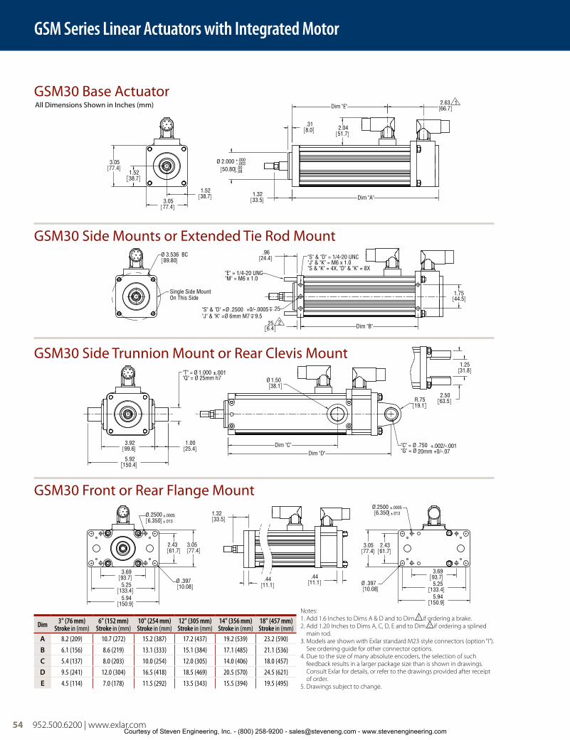
54 952.500.6200 | www.exlar.com
GSM30 Base Actuator
GSM30 Side Mounts or Extended Tie Rod Mount
GSM30 Side Trunnion Mount or Rear Clevis Mount
GSM30 Front or Rear Flange Mount
Dim 3" (76 mm)Stroke in (mm)
6" (152 mm) Stroke in (mm)
10" (254 mm) Stroke in (mm)
12" (305 mm) Stroke in (mm)
14" (356 mm) Stroke in (mm)
18" (457 mm) Stroke in (mm)
A 8.2 (209) 10.7 (272) 15.2 (387) 17.2 (437) 19.2 (539) 23.2 (590)
B 6.1 (156) 8.6 (219) 13.1 (333) 15.1 (384) 17.1 (485) 21.1 (536)
C 5.4 (137) 8.0 (203) 10.0 (254) 12.0 (305) 14.0 (406) 18.0 (457)
D 9.5 (241) 12.0 (304) 16.5 (418) 18.5 (469) 20.5 (570) 24.5 (621)
E 4.5 (114) 7.0 (178) 11.5 (292) 13.5 (343) 15.5 (394) 19.5 (495)
3.0577.4
3.0577.4
1.5238.7
1.5238.7
2.0451.7
2.6366.7
1Dim "E"
Ø 2.000 +-.000.003
50.80 -.00.08
.318.0
1.3233.5 Dim "A"
Ø 3.53689.80
BC
Single Side MountOn This Side
.256.4
2Dim "B"
1.7544.5
.9624.4
"S" & "D" =Ø .2500 +0/-.0005 .25"J" & "K" =Ø 6mm M7 9.5
"E" = 1/4-20 UNC"M" = M6 x 1.0
"S" & "D" = 1/4-20 UNC"J" & "K" = M6 x 1.0"S & "K" = 4X, "D" & "K" = 8X
"T" = Ø 1.000 ±.001"Q" = Ø 25mm h7
3.9299.6
1.0025.4
5.92150.4
Dim "C"Dim "D"
R.7519.1
"C" = Ø .750 +.002/-.001"G" = Ø 20mm +0/-.07
Ø 1.5038.1
2.5063.5
1.2531.8
5.94150.9
5.25133.4
3.6993.7
2.4361.7
3.0577.4
Ø.2500 ±.00056.350 ±.013
Ø .39710.08
1.3233.5
.4411.1
.4411.1
3.6993.75.25
133.45.94
150.9
2.4361.7
3.0577.4
Ø .39710.08
Ø.2500 ±.00056.350 ±.013
All Dimensions Shown in Inches (mm)
Notes:1. Add 1.6 Inches to Dims A & D and to Dim△1 if ordering a brake.2. Add 1.20 Inches to Dims A, C, D, E and to Dim△2 if ordering a splined
main rod.3. Models are shown with Exlar standard M23 style connectors (option “I”).
See ordering guide for other connector options.4. Due to the size of many absolute encoders, the selection of such
feedback results in a larger package size than is shown in drawings. Consult Exlar for details, or refer to the drawings provided after receipt of order.
5. Drawings subject to change.
GSM Series Linear Actuators with Integrated Motor
Courtesy of Steven Engineering, Inc. - (800) 258-9200 - [email protected] - www.stevenengineering.com

952.500.6200 | www.exlar.com 55
3.9099.1
3.9099.1
1.9549.5
1.9549.5
.102.5
Ø 2.500 +-.000.003
63.50 -.00.08
1.6541.9
2.0451.7
Dim "E"2.6366.7
1
Dim "A"
Ø 4.243107.76
BC
Single Side MountOn This Side 1.75
44.5
.317.9
2Dim "B"
"S" & "D" =Ø .3750 +0/-.0005 .44"J" & "K" =Ø 8mm M7 12
1.3835.1
"S" & "D" = 3/8-16 UNC"J" & "K" = M10 x 1.5"S & "K" = 4X, "D" & "K" = 8X"E" = 3/8-16 UNC
"M" = M8 x 1.25
4.90124.46.90
175.2
"T" = Ø 1.500 ±.001"Q" = Ø 35mm h7
1.0025.4
Ø 2.0050.8
Dim "C"Dim "D"
R.7519.1
"C" = Ø .750 +.002/-.001"G" = Ø 20mm +0/-.07
1.2531.8
2.5063.5
3.8096.5
6.80172.77.68
195.1
2.9274.2
Ø.51613.10
5.25133.4
Ø.250 ±.0016.350 ±.025 1.65
41.9
.6315.9
.6315.9
5.25133.46.80
172.77.68
195.1
2.9274.2
3.8096.5
Ø .51613.10
Ø .250 ±.0016.350 ±.025
GSM40 Base Actuator
GSM40 Side Mounts or Extended Tie Rod Mount
GSM40 Side Trunnion Mount or Rear Clevis Mount
GSM40 Front or Rear Flange Mount
Dim 4" (102 mm) Stroke in (mm)
6" (152 mm) Stroke in (mm)
8" (203 mm) Stroke in (mm)
10" (254 mm) Stroke in (mm)
12" (305 mm) Stroke in (mm)
18" (457 mm) Stroke in (mm)
A 10.6 (269) 12.6 (320) 14.6 (370) 16.6 (421) 18.6 (472) 24.6 (624)
B 8.3 (211) 10.3 (262) 12.3 (313) 14.3 (364) 16.3 (414) 22.3 (567)
C 4.0 (102) 6.0 (152) 8.0 (203) 10.0 (254) 12.0 (305) 18.0 (457)
D 12.3 (312) 14.3 (363) 16.3 (415) 18.3 (466) 20.3 (516) 26.3 (669)
E 6.9 (175) 8.9 (226) 10.9 (277) 12.9 (328) 14.9 (378) 20.9 (531)
All Dimensions Shown in Inches (mm)
Notes:1. Add 2.33 Inches to Dims A & D and to Dim△1 if ordering a brake.2. Add 1.77 Inches to Dims A, C, D, E and to Dim△2 if ordering a
splined main rod.3. Models are shown with Exlar standard M23 style connectors
(option “I”). See ordering guide for other connector options.4. Due to the size of many absolute encoders, the selection of such
feedback results in a larger package size than is shown in drawings. Consult Exlar for details, or refer to the drawings provided after receipt of order.
5. Drawings subject to change.
GSM Series Linear Actuators with Integrated Motor
GSM
Ser
ies
Courtesy of Steven Engineering, Inc. - (800) 258-9200 - [email protected] - www.stevenengineering.com

56 952.500.6200 | www.exlar.com
Actuator Rod End Options
Standard Rod Ends
Rod Clevis Dimensions
Spherical Rod Eye Dimensions
A B ØC D ØE F Male U.S. Male Metric Female U.S. Female Metric
GSM20in (mm) 0.813 (20.7) 0.375 (9.5) 0.500 (12.7) 0.200 (5.1) 0.440 (11.2) 0.750 (19.1) 3/8 – 24 UNF – 2A M8 x 1 6g 5/16 – 24 UNF – 2B M8 x 1 6h
GSM30in (mm) 0.750 (19.1) 0.500 (12.7) 0.625 (15.9) 0.281 (7.1) 0.562 (14.3) 0.750 (19.1) 7/16 – 20 UNF– 2A M12 x 1.75* 6g 7/16 – 20 UNF – 2B M10 x 1.5 6h
GSM40in (mm) 1.500 (38.1) 0.750 (19.1) 1.000 (25.4) 0.381 (9.7) 0.875 (22.2) 1.000 (25.4) 3/4 – 16 UNF – 2A M16 x 1.5 6g 5⁄8 – 18 UNF – 2B M16 x 1.5 6h
Part numbers for rod attachment options indicate the through hole size or pin diameter. Before selecting a spherical rod eye for use with a GSM series actuator, please consult the information on the anti-rotation option for the GSM actuators. Spherical rod eyes will allow the rod to rotate if the load is not held.
For Rod End with Splined Main Rod, see pg 36
D DE
øF
C
B
A
øG
H øJ
K
D
A
H
FG
øB
C
J K
E
AA
A
B
øA
C
D
F
E
D DE
øF
C
B
A
øG
HøJ
K
C CB
A
øE
øD
A
A
øC
øC
D
D
øE
øE
B
B
MaleThread
MaleThread
B
B
D
D
øE
øE
F
F
øC
øC
FemaleThread
FemaleThread
*A Dim = 40mm
in (mm) GSM20 RC038 GSM30 RC050 GSM40 RC075
A 0.810 (20.6) 0.75 (19.1) 1.125 (28.58)
B 0.785 (19.9) 0.75 (19.1) 1.25 (31.75)
C 1.595 (40.5) 1.50 (38.1) 2.375 (60.3)
D 0.182 (4.6) 0.50 (12.7) 0.625 (15.88)
E 0.386 (9.8) 0.765 (19.43) 1.265 (32.13)
ØF 0.373 (9.5) 0.50 (12.7) 0.75 (19.1)
ØG 0.951 (24.2) 1.00 (25.4) 1.50 (38.1)
H NA 1.00 (25.4) 1.25 (31.75)
ØJ NA 1.00 (25.4) 1.25 (31.75)
K 3/8-24 7/16-20 3/4-16
in (mm) GSM20 SRM038 GSM30 SRM044 GSM40 SRM075
A 1.625 (41.3) 1.81 (46.0) 2.88 (73.2)
ØB .375 (9.525) 0.438 (11.13) 0.75 (19.1)
C .906 (23.0) 1.06 (26.9) 1.72 (43.7)
D 1.0 (25.4) 1.13 (28.7) 1.75 (44.5)
E 6 deg 14 deg 14 deg
F .406 (10.3) 0.44 (11.1) 0.69 (17.5)
G .500 (12.7) 0.56 (14.2) 0.88 (22.3)
H .688 (17.4) 0.75 (19.1) 1.13 (28.7)
J .562 (14.3) 0.63 (16.0) 1.00 (25.4)
K 3/8-24 7/16-20 3/4-1Drawings subject to change. Consult Exlar for certified drawings.
D
A
H
FG
øB
C
J K
E
GSM Series Linear Actuators with Integrated Motor
Courtesy of Steven Engineering, Inc. - (800) 258-9200 - [email protected] - www.stevenengineering.com
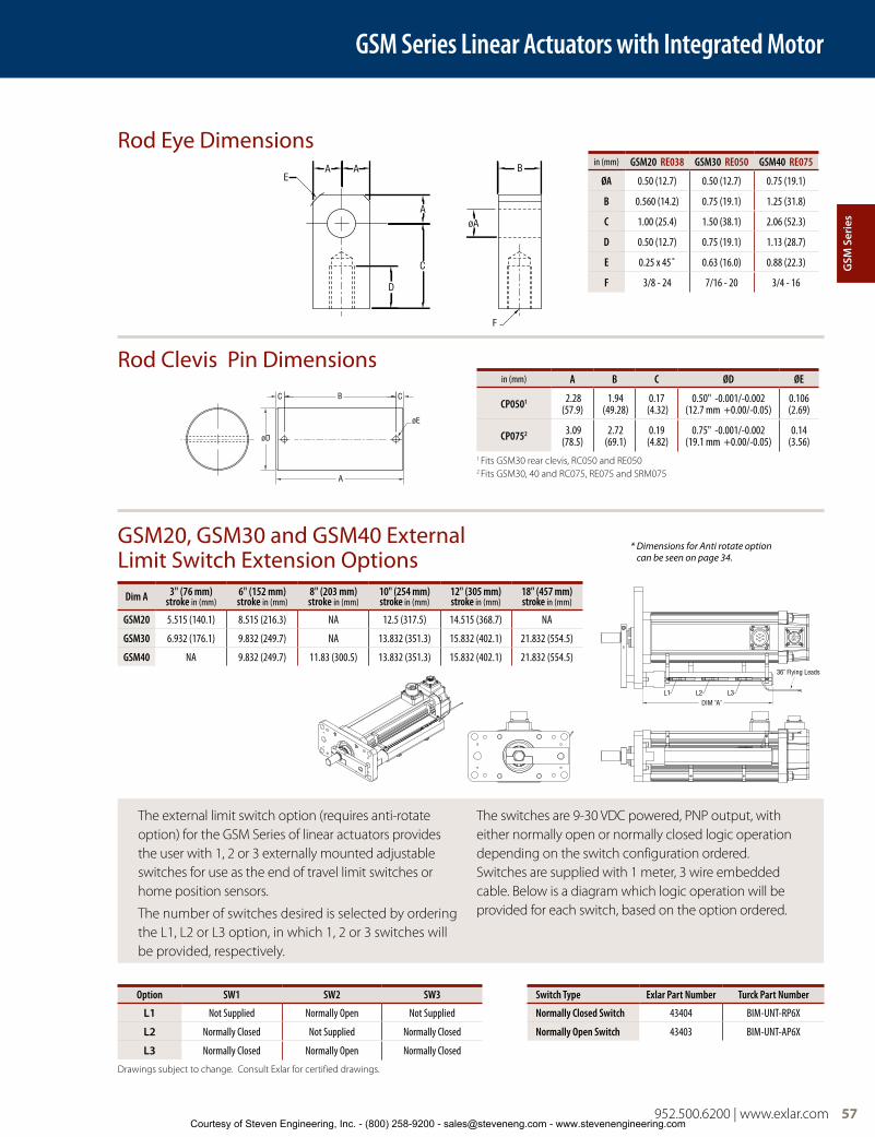
952.500.6200 | www.exlar.com 57
Rod Eye Dimensions
Rod Clevis Pin Dimensions
GSM20, GSM30 and GSM40 External Limit Switch Extension Options
C CB
A
øE
øD
DIM "A"
36" Flying Leads
L1 L2 L3
in (mm) GSM20 RE038 GSM30 RE050 GSM40 RE075
ØA 0.50 (12.7) 0.50 (12.7) 0.75 (19.1)
B 0.560 (14.2) 0.75 (19.1) 1.25 (31.8)
C 1.00 (25.4) 1.50 (38.1) 2.06 (52.3)
D 0.50 (12.7) 0.75 (19.1) 1.13 (28.7)
E 0.25 x 45˚ 0.63 (16.0) 0.88 (22.3)
F 3/8 - 24 7/16 - 20 3/4 - 16
in (mm) A B C ØD ØE
CP0501 2.28 (57.9)
1.94 (49.28)
0.17 (4.32)
0.50" -0.001/-0.002 (12.7 mm +0.00/-0.05)
0.106 (2.69)
CP0752 3.09(78.5)
2.72 (69.1)
0.19 (4.82)
0.75" -0.001/-0.002 (19.1 mm +0.00/-0.05)
0.14(3.56)
1 Fits GSM30 rear clevis, RC050 and RE0502 Fits GSM30, 40 and RC075, RE075 and SRM075
AA
A
B
øA
C
D
F
E
* Dimensions for Anti rotate option can be seen on page 34.
Dim A 3" (76 mm)stroke in (mm)
6" (152 mm) stroke in (mm)
8" (203 mm)stroke in (mm)
10" (254 mm)stroke in (mm)
12" (305 mm) stroke in (mm)
18" (457 mm)stroke in (mm)
GSM20 5.515 (140.1) 8.515 (216.3) NA 12.5 (317.5) 14.515 (368.7) NA
GSM30 6.932 (176.1) 9.832 (249.7) NA 13.832 (351.3) 15.832 (402.1) 21.832 (554.5)
GSM40 NA 9.832 (249.7) 11.83 (300.5) 13.832 (351.3) 15.832 (402.1) 21.832 (554.5)
The external limit switch option (requires anti-rotate option) for the GSM Series of linear actuators provides the user with 1, 2 or 3 externally mounted adjustable switches for use as the end of travel limit switches or home position sensors.
The number of switches desired is selected by ordering the L1, L2 or L3 option, in which 1, 2 or 3 switches will be provided, respectively.
The switches are 9-30 VDC powered, PNP output, with either normally open or normally closed logic operation depending on the switch configuration ordered. Switches are supplied with 1 meter, 3 wire embedded cable. Below is a diagram which logic operation will be provided for each switch, based on the option ordered.
Option SW1 SW2 SW3 Switch Type Exlar Part Number Turck Part Number
L1 Not Supplied Normally Open Not Supplied Normally Closed Switch 43404 BIM-UNT-RP6X
L2 Normally Closed Not Supplied Normally Closed Normally Open Switch 43403 BIM-UNT-AP6X
L3 Normally Closed Normally Open Normally Closed
Drawings subject to change. Consult Exlar for certified drawings.
GSM Series Linear Actuators with Integrated Motor
GSM
Ser
ies
Courtesy of Steven Engineering, Inc. - (800) 258-9200 - [email protected] - www.stevenengineering.com

58 952.500.6200 | www.exlar.com
GSM Series Ordering Information
AA = GSM Actuator Size (nominal)20 = 2 in (60 mm) frame30 = 3 in (80 mm) frame40 = 4 in (100 mm) frame
BB = Stroke Length03 = 3 in (76 mm) GSM20 and GSM3004 = 4 in (102 mm) GSM4006 = 6 in (152 mm) all models
5.9 in (150 mm) GSM3008 = 8 in (203 mm) GSM4010 = 10 in (254 mm) GSM20, GSM30 and
GSM4012 = 12 in (305 mm) GSM20, GSM30 and
GSM4014 = 14 in (356 mm) GSM3018 = 18 in (457 mm) GSM30 and GSM40
CC = Lead01 = 0.1 in (2.54 mm) (all models)02 = 0.2 in (5.08 mm) (all models)04 = 0.4 in (10.16 mm) (GSM20)05 = 0.5 in (12.7 mm) (GSM30 and
GSM40)08 = 0.75 in (19.05 mm) (GSM40)3
D = ConnectionsI = Exlar standard M23 style M = Manufacturer’s connector1
A = MS style (anodized)D = MS style (electroless nickel) B = Embedded leads 3 ft. std.P = Embedded leads w/plug 3 ft.
standard w/ “A” plugJ = Embedded leads w/ “I” plug,
3 ft. stdX = Special (please specify)
E = MountingB = Front and rear flangeC = Rear clevisF = Front flangeR = Rear flangeS = Side mountD = Double side mount18
T = Side trunnionE = Extended tie rodsJ = Metric side mountK = Metric double side mount18
Q = Metric side trunnionM = Metric extended tie rodsG = Metric rear clevisZ = Clevis mount with same pin to pin
as SR SeriesX = Special (please specify)
F = Rod End Thread/Rod MaterialM = Male, US std. threadA = Male, metric threadF = Female, US std. threadB = Female, metric threadW = Male, US std. thread SS16
R = Male metric thread SS16
V = Female, US std. thread SS16
L = Female, metric thread SS16
X = Special (please specify)
GGG = Feedback Type (Also specify the Amplifier/Drive Model being used when ordering)- Standard Incremental Encoder – 2048 line
(8192 cts) per rev. index pulse, Hall commutation, 5vdc
- Standard Resolver – Size 15, 1024 line (2048 cts) per rev. two pole resolver
- Motor files for use with select Emerson/CT, Rockwell /AB and Danaher/Kollmorgen Drives are available at www.exlar.com
Custom Feedback: contact your local sales representative:XX1 = Wiring and feedback device information
must be provided and new feedback callout will be created
Allen-Bradley/Rockwell: (Note: AB8, AB9 and ABB callouts are available only on spare/replacement actuators that have been previously ordered. For all new configurations using a Rockwell drive, please select from the options below. Consult Exlar for integration questions)RA1 = Hiperface Stegmann SKM36 multi-turn
absolute encoder. MPL Type V feedback (128 sin/cos) and Type 7 SpeedTec connectors and wiring when using the “M” connector option. 20 and 30 frame sizes only. (Formerly ABB)12
RA2 = Hiperface Stegmann SRM50 multi-turn absolute encoder. MPL Type M feedback (1024 sin/cos) and Type 7 SpeedTec connectors and wiring when using the “M” connector option. 40 frame size only. (Formerly AB9)12
RA3 = Standard incremental encoder. MPL Type M feedback (2048 line) and Type 7 SpeedTec connector and wiring when using the “M” connector option. (Formerly AB8)
RA4 = Standard Resolver. MPL Type R feedback (4 pole) and Type 7 SpeedTec connectors and wiring when using the “M” connector option. (Formerly AB6)
AMKASYN:AK1 = EnDat Heidenhain EQN1325 multi-turn
absolute encoder – 40 Frame Size. DS motor wiring w/M23 euro connectors for ‘M’ option
AK2 = EnDat Heidenhain EQN1125 multi-turn absolute encoder – 20-30 Frame Size. DS motor wiring w/M23 euro connectors for ‘M’ option
Advanced Motion Control:AM1 = Standard Incremental Encoder AM2 = Encoder 1000 line, w/commutation, 5 VDCAM3 = Standard ResolverAM5 = Encoder 5000 line, w/commutation, 5 VDCAPI Controls:AP1 = Standard ResolverAP2 = Standard Incremental Encoder Aerotech:AR1 = Encoder 5000 line, w/commutation, 5 VDCAR2 = Standard Incremental Encoder Baldor:BD2 = Std Resolver – BSM motor wiring
w/M23 connectors for ‘M’ option
BD3 = Std Incremental Encoder – BSM motor wiring w/M23 connectors for ‘M’ option
Beckhoff:BE2 = EnDat Heidenhain EQN1125 multi-turn
absolute encoder – AM5XX motor wiring w/M23 euro connectors for ‘M’ option
Baumueller:BM2 = Standard ResolverB&R Automation:BR1 = Standard ResolverBR2 = EnDat Heidenhain EQN1125/1325
multi-turn absolute encoder – 8LS/8LM motor wiring w/M23 euro connectors for ‘M’ option
Copley Controls:CO1 = Standard Incremental EncoderCO2 = Standard ResolverControl Techniques/Emerson:CT1 = Hiperface Stegmann SRM050 multi-turn
absolute encoder – 40 Frame Size. FM/UM/EZ motor wiring w/M23 euro connectors for ‘M’ option
CT3 = Hiperface Stegmann SKM036 multi-turn absolute encoder – 20-30 Frame Size. FM/UM/EZ motor wiring w/M23 euro connectors for ‘M’ option
CT4 = Standard Incremental Encoder – FM/UM/EZ motor wiring w/M23 euro connectors for ‘M’ option
CT5 = Standard Resolver – FM/UM/EZ motor wiring w/M23 euro connectors for ‘M’ option
CT7 = Encoder 5000 line, w/commutation, 5 VDC – FM/UM/EZ motor wiring w/M23 euro connectors for ‘M’ option
Delta Tau Data Systems:DT1 = Encoder 1000 line, w/commutation, 5 VDCDT2 = Standard ResolverElmo Motion Control:EL1 = Standard ResolverEL2 = Standard Incremental EncoderEL3 = EnDat Heidenhain EQN1125 multi-turn
absolute encoderEmerson/Control Techniques:EM2 = Std Incremental Encoder – NT motor
wiring w/MS connectors for ‘M’ optionEM5 = Encoder 5000 line, with commutation,
5 VDC – NT motor wiring w/MS connectors for ‘M’ option
Elau:EU1 = Hiperface Stegmann SRM050 multi-turn
absolute encoder – 40 Frame Size. SH motor wiring w/MS connectors for ‘M’ option
EU4 = Hiperface Stegmann SKM036 multi-turn absolute encoder – 20-30 Frame Size. SH motor wiring w/MS connectors for ‘M’ option
Exlar:EX4 = Standard ResolverEX5 = Standard Resolver with KTY84 thermistorEX6 = EnDat Heidenhain EQN/125 multi-turn
absolute encoder EX7 = Incremental encoder, 5000 line with
commutation, 5Vdc EX8 = Hiperface Stegmann SRM50 multi-turn
absolute encoder
GSMAA - BB - CC - DEF - GGG - HHH - II - (XX..XX)
For cables and accessories see page 116.58 952.500.6200 | www.exlar.comCourtesy of Steven Engineering, Inc. - (800) 258-9200 - [email protected] - www.stevenengineering.com

952.500.6200 | www.exlar.com 59
GSM Series Ordering Information
G&L Motion Control/Danaher Motion:GL1 = Std Incremental Encoder – HSM motor
wiring w/ MS connectors for ‘M’ optionGL2 = Std Incremental Encoder – LSM-MSM
motor wiring w/M23 euro connectors for ‘M’ option
GL3 = Std Incremental Encoder – NSM motor wiring w/MS connectors for ‘M’ option
GL4 = EnDat Heidenhain EQN1125 multi-turn absolute encoder – AKM motor wiring w/M23 euro connectors for ‘M’ option
Infranor:IF1 = Standard ResolverIndramat/Bosch-Rexroth:IN6 = Std Resolver – MKD/MHD motor wiring
w/M23 euro connectors for ‘M’ optionIN7 = Hiperface Stegmann SKM036 multi-turn
absolute encoder – MSK motor wiring w/M23 euro connectors for ‘M’ option – plug & play option
Jetter Technologies:JT1 = Standard Resolver – JH/JL motor wiring
w/M23 euro connectors for ‘M’ optionKollmorgen/Danaher:.06KM4 = EnDat Heidenhain EQN1325 multi-turn
absolute encoder – AKM motor wiring w/M23 euro connectors for ‘M’ option
KM5 = Standard Resolver – AKM motor wiring w/M23 euro connectors for ‘M’ option
KM6 = Standard Incremental Encoder – AKM motor wiring w/M23 euro connectors for ‘M’ option
Lenze/AC Tech: LZ1 = Hiperface Stegmann SRM050 multi-turn
absolute encoder – MCS motor wiring w/M23 euro connectors for ‘M’ option
LZ5 = Std Resolver – MCS motor wiring w/ M23 euro connectors for ‘M’ option
LZ6 = Std Incremental Encoder – MCS motor wiring w/ M23 euro connectors for ‘M’ option
Metronix:MX1 = Standard ResolverMX2 = Hiperface Stegmann SKM036
multi-turn absolute encoderMX3 = EnDat Heidenhain EQN1125 multi-turn
absolute encoderMitsubishi:MT1 = Mitsubishi Absolute Encoder – HF-SP motor
wiring with ‘M’ option (N/A with clevis)Momentum:MN1 = Hyperface Stegmann SRM050 multi-turn
absolute encoder – MN motor wiring w/M23 connectors for ‘M’ option
MN2 = EnDat Heidenhain EQN1325 multi-turn absolute encoder – MN motor wiring connectors for ‘M’ option
MN3 = Std incremental encoder – MN motor wiring w/M23 connectors for ‘M’ option
MN4 = Std resolver – MN motor wiring w/M23 connectors for ‘M’ option
Moog:MG1 = Standard ResolverOrmec:OR1 = Standard Resolver OR2 = Std Incremental Encoder – G series motor
wiring w/MS connectors for ‘M’ option
Parker Compumotor:PC6 = Std Incremental Encoder – SMH motor
wiring w/M23 connectors for ‘M’ option – European only
PC7 = Std Resolver – SMH motor wiring w/M23 connectors for ‘M’ option – European only
PC8 = Std Incremental Encoder – MPP series motor wiring w/PS connectors for ‘M’ option –US Only
PC9 = Hiperface Stegmann SRM050 multi-turn absolute encoder – MPP motor wiring w/PS connectors for ‘M’ option – US Only
PC0 = Std Resolver – MPP motor wiring w/PS connectors for ‘M’ option – US Only
Pacific Scientific:PS2 = Standard Incremental EncoderPS3 = Standard Resolver – PMA motor wiring
w/M23 connectors for ‘M’ optionStober Drives:SB2 = Standard Resolver ED/EK motor wiring
w/M23 connector for ‘M’ optionSB3 = EnDat Heidenhain EQN1125 multi-turn
absolute encoder – ED/EK motor wiring w/M23 euro connectors for ‘M’ option
Siemens:SM2 = Standard Resolver – 1FK7 motor wiring
w/M23 connectors for ‘M’ optionSM3 = EnDat Heidenhain EQN1325 multi-turn
absolute encoder – 40 Frame Size. 1FK7 motor wiring w/M23 euro connectors for ‘M’ option
SM4 = EnDat Heidenhain EQN1125 multi-turn absolute encoder – 20-30 Frame Size. 1FK7 motor wiring w/M23 euro connectors for ‘M’ option
SEW/Eurodrive:SW1 = Standard Resolver – CM motor wiring
w/ M23 euro connectors for ‘M’ optionSW2 = Standard Incremental EncoderSW3 = Hiperface Stegmann SRM050 multi-turn
absolute encoder – CM motor wiring w/ M23 euro connectors for ‘M’ option
Yaskawa:YS2 = Yaskawa Absolute Encoder – SGMGH
motor wiring 40 Exlar Frame SizeYS3 = Yaskawa Absolute Encoder – SGMGH
motor wiring 20/30 Exlar Frame SizesHHH = Motor Stator2 – All 8 Pole14
II = Motor Speed30 = 3000 rpm, GSM30, GSM4050 = 5000 rpm, GSM2001- 99 = Customer specified base speed
XX .. XX = Travel and Housing Options (please list desired options)
Travel OptionsAR = External anti-rotate13
HW = Manual drive, Handwheel with interlock switch10, 15
PB = Protective bellows11
SR = Splined main rod
Travel Options Con’tRB = Rear brakeRD = Manual drive, Simple Rear9, 15
SD = Manual drive, Side Hex15
PF = Preloaded follower4,17
L1/L2/L3 = External limit switch8
XT = Special travel options, high temperature bellows11 or angular contact bearings
Housing OptionsEN = Electroless nickel platingXH = Special housingP5 = IP65S sealing option5
HC = Type III hard coat anodized6
XL = Special lubrication, food grade or Mobilgrease 28, specify
XM = Special motor options
Absolute Linear FeedbackLT = ICT, including signal conditioner4, 7, 9
##### = Part No. Designator for Specials Optional 5 digit assigned part number to designate unique model numbers for specials.
Note:1. Available as described in Feedback Types.2. Stator voltage and pole options allow for catalog
rated performance at varying amplifier bus voltages and pole configuration requirements.
3. 0.75 lead not available over 12" stroke4. The dynamic load rating of zero backlash, preloaded
screws is 63% of the dynamic load rating of the standard non-preloaded screws. The calculated travel life of a preloaded screw will be 25% of the calculated travel life of the same size and lead of a non-preloadedscrew. Preloaded follower is not available with absolute linear (LT) internal feedback option.
5. Not available with splined main rod option.6. This housing option would typically be
accompanied by the choice of the electroless nickel connectors if a connectorized unit were selected. This choice may also indicate the need for special material main rods or mounting.
7. Linear feedback is not available in the GSM20 and not available in 14" or greater stroke. Also not available with PF or absolute feedback
8. Requires AR option9. Not available with absolute feedback.
10. Not available on GSM20.11. Not available with extended tie rod mounting option.12. Not compatible with Kinetix 300 drives.13. A second anti-rotate arm is used on GSM 20, 30 & 40
for 10 inch and longer stroke.14. See page 52 for optimized stators.15. N/A with holding brake unless application details
are discussed with your local sales representative.16. Consult with your local sales representative when
ordering splined stainless steel main rod.17. Preloaded follower includes angular contact bearings.18. Anti-rotate with D or K mounting N/A on 10" or
longer stroke.
118 = 1 stack 115 Vrms
158 = 1 stack 400 Vrms218 = 2 stack 258 = 2 stack
138 = 1 stack 230 Vrms
168 = 1 stack 460 Vrms238 = 2 stack 268 = 2 stack
952.500.6200 | www.exlar.com 59
GSM
Ser
ies
Courtesy of Steven Engineering, Inc. - (800) 258-9200 - [email protected] - www.stevenengineering.com

K Series Linear ActuatorsExlar K Series actuators offer Exlar’s roller screw technology in varying performance levels and allow the use of third party motors.
A Universal Design Providing Ultimate Flexibility
The K Series actuator provides an ideal replacement for pneumatic and hydraulic cylinders in linear motion control applications. Unlike most suppliers who employ ballscrews, Exlar’s K Series linear actuators utilize a planetary roller screw assuring long life and high resistance to shock. This makes Exlar actuators far superior to alternative methods for applying all-electric linear actuation in industrial and military applications.
K Series actuators are offered in 60, 75 and 90 mm frame sizes with dimensions and form-factor consistent with ISO Metric pneumatic cylinder specifications. This allows convenient substitution of Exlar actuators for existing pneumatic and hydraulic actuators.
K Series Linear Actuators
60 952.500.6200 | www.exlar.com
UltimateFlexibility
KX Series actuators provides high performance planetary roller screw performance far superior to any other available rotary-to-linear conversion technologies. The KX Series is the ideal choice for demanding applications in industrial automation, mobile equipment, military, process control or many others where millions of inches of travel under load is expected.
KM Series actuators employ a lower cost planetary roller screw design suited for applications that do not require the long life offered in the KX Series. This option still provides twice the life of similarly sized ball
screw actuators along with the efficiency and resistance to shock associated with roller screws.
KA Series actuators are constructed using an Acme screw and are ideally suited for low duty cycle, slow speed applications involving occasional repositioning of the load. The KA Series is an excellent choice for applications that position and hold a load, and when backdriving must be prevented.
Inline mounting configuration
Three Performance Grades to Meet Your Exact Application Needs and Budget
K Series actuators from Exlar provide a truly universal solution for linear motion rod style actuator applications. Two grades of planetary roller screws for dynamic applications are offered as well as an Acme screw for lower cost, static applications where position change is infrequent and/or slow. These choices allow you to realize the travel life required of the application while meeting budget constraints.
Courtesy of Steven Engineering, Inc. - (800) 258-9200 - [email protected] - www.stevenengineering.com

Roller Screw Basics
Exlar’s roller screw is a mechanism for converting the rotary motion produced by a motor into linear motion, similar to Acme screws or ball screws. Unlike those devices, however, roller screws can carry heavy loads for thousands of hours in the most arduous conditions. This makes roller screws the ideal choice for demanding, continuous-duty linear motion applications. The difference is in the roller screw’s design for transmitting forces. Multiple threaded helical rollers are assembled in a planetary arrangement around a threaded shaft which converts a motor’s rotary motion into linear movement of the shaft or nut.
Compare a similar size ball screw to Exlar’s planetary roller screw design and see many more contact points on the roller screw. This results in higher load-carrying capacity and improved stiffness.
The Exlar Advantage Universal Mounting OptionsThe K Series offers a wide variety of fixed and adjustable mounting accessories consistent with NFPA inch and ISO Metric pneumatic cylinder standards. The mounting options include:
• Front Flange • Rear Flange• Adjustable Side Trunnions • Rear Clevis (parallel and inline motor)• Foot Mount • End Angles• Rear Eye
Standard Actuator ConstructionThe standard K Series actuator design includes an anodized aluminum housing offering a high level of corrosion resistance in many environments. The standard main rod is plated steel with a stainless steel rod end insert providing excellent wear characteristics.
Special Materials and CoatingsExlar offers a variety of special materials and coating options for applications which require a higher level of corrosion-resistance. The aluminum actuator body components can be manufactured with alternative coatings such as Type III hard coat anodizing, electroless nickel plating or epoxy coating. The actuator’s main rod can be provided in stainless steel construction.
Sealed Body DesignThe standard body design of the K Series provides an IP54S sealed housing. IP65S sealing is available when inline or parallel motor mount is specified. This allows the actuators to be used in applications where water spray is present.
Motor Mounting OptionsThe K Series allows for complete flexibility in the type and style of motor to drive the actuator. Types of motors compatible with K Series actuators include DC motor, stepper and servo motors. The K Series can be ordered as a base unit without motor mounting allowing customers to manufacture their own mount.
For convenience these actuators are available with preconfigured motor mounts. Exlar maintains a large library of motor mounting dimensional information for most manufacturers’ servos and stepper motors.
The inline mount places the motor on the input end of the actuator and allows the most compact form factor. In addition, Exlar
offers a clevis mount attached to the rear of the inline-mounted motor for rear mounting.
The parallel motor mounts (side mount) utilize a belt drive system to transmit the motor torque to the
actuator input shaft. Belt reductions of 1:1 and 2:1 are offered allowing you to conveniently
match the speed and output force to properly apply your K Series actuator to your specific application.
K Series Linear Actuators
952.500.6200 | www.exlar.com 61
Parallel mounting configuration
K S
erie
s
Courtesy of Steven Engineering, Inc. - (800) 258-9200 - [email protected] - www.stevenengineering.com

62 952.500.6200 | www.exlar.com
K Series Performance Specifications
Model No.
Nominal Frame Sizemm (in)
Screw Leadmm (in)
Maximum Force5
kN (lbf)
Linear Speed at Max Rated RPM mm/sec (in/sec)
Dynamic Load RatingkN (lbf)
Life at Maximum Force1
km (in x 106)
Maxium Input Torque4
Nm (lbf-in)
Max Rated RPM @ Input
Shaft RPM
K60 Roller Screw Models
KM60-05 60 (2.36) 5 (0.1969) 6.0 (1,350) 417 (16.4) 7.7 (1,725) 10.4 (0.4) 6 (53) 5,000
KM60-10 60 (2.36) 10 (0.3937) 3.0 (675) 833 (32.8) 6.8 (1,525) 115.3 (4.5) 6 (53) 5,000
KX60-05 60 (2.36) 5 (0.1969) 6.0 (1,350) 417 (16.4) 12.2 (2,738) 41.7 (1.6) 6 (53) 5,000
KX60-10 60 (2.36) 10 (0.3937) 3.0 (675) 833 (32.8) 10.8 (2,421) 461.4 (18.2) 6 (53) 5,000
K60 Acme Screw Models 2,3
KA60-01 60 (2.36) 2.54 (0.1) 3.7 (830) 56 (2.2) NA NA 6 (53) 1,330
KA60-02 60 (2.36) 5.08 (0.2) 3.1 (700) 146 (5.8) NA NA 6 (53) 1,725
K75 Roller Screw Models
KM75-05 75 (2.95) 5 (0.1969) 11.1 (2,500) 333 (13.1) 16.1 (3,620) 15.2 (0.6) 11 (98) 4,000
KM75-10 75 (2.95) 10 (0.3937) 5.6 (1,250) 666 (26.2) 13.5 (3,036) 143.3 (5.6) 11 (98) 4,000
KX75-05 75 (2.95) 5 (0.1969) 11.1 (2,500) 333 (13.1) 25.6 (5,746) 60.7 (2.4) 11 (98) 4,000
KX75-10 75 (2.95) 10 (0.3937) 5.6 (1,250) 666 (26.2) 21.4 (4,820) 573.3 (22.6) 11 (98) 4,000
K75 Acme Screw Models 2,3
KA75-01 75 (2.95) 2.54 (0.1) 6.0 (1,355) 42 (1.7) NA NA 11 (98) 1,000
KA75-02 75 (2.95) 5.08 (0.2) 5.1 (1,139) 110 (4.3) NA NA 11 (98) 1,300
K90 Roller Screw Models
KM90-05 90 (3.54) 5 (0.1969) 15.6 (3,500) 250 (9.8) 32.4 (7,275) 44.9 (1.8) 16 (137) 3,000
KM90-10 90 (3.54) 10 (0.3937) 7.8 (1,750) 500 (19.7) 30.0 (6,750) 573.8 (22.6) 16 (137) 3,000
KX90-05 90 (3.54) 5 (0.1969) 15.6 (3,500) 250 (9.8) 51.4 (11,548) 179.6 (7.1) 16 (137) 3,000
KX90-10 90 (3.54) 10 (0.3937) 7.8 (1,750) 500 (19.7) 47.7 (10,715) 2,295 (90.4) 16 (137) 3,000
K90 Acme Screw Models 2,3
KA90-01 90 (3.54) 2.54 (0.1) 6.9 (1,550) 31 (1.2) NA NA 16 (137) 730
KA90-02 90 (3.54) 5.08 (0.2) 5.7 (1,300) 73 (2.9) NA NA 16 (137) 860
1. See page 165 for life calculation information.
2. Acme screw life expectancy: As a result of the high friction inherent to acme screws, life expectancy is unpredictable. Load, duty cycle, speed, temp, and lubrication all affect the amount of heat generated and thread wear by the acme nut which ultimately determines the life of the mechanism. Acme screws typically have lower life expectancies than roller screws and should only be used in low duty cycle applications.
3. P x V for ACME screws should be kept below 0.1 P = Force/Max Force; V = Speed/Max Speed
4. Input torque should be limited such that Max Force is not exceeded. For a parallel belt ratio, the input torque ratings must be divided by the belt ratio for allowable motor torque. The output force ratings remain the same.
5. Maximum allowable actuator–generated force that can be applied routinely. Exceeding this force may result in permanent damage to the actuator. For maximum allowable externally-applied axial forces, consult factory. For high force, short stroke applications, consult factory.
K Series Linear Actuators with Integrated Motor
Courtesy of Steven Engineering, Inc. - (800) 258-9200 - [email protected] - www.stevenengineering.com

952.500.6200 | www.exlar.com 63
K Series Linear Actuators with Integrated Motor
K Series Mechanical SpecificationsKM60 KX60 KA60 KM75 KX75 KA75 KM90 KX90 KA90
Nominal Backlash mm(in)
0.20(0.008)
0.10(0.004)
0.36(0.014)
0.20(0.008)
0.10(0.004)
0.36(0.014)
0.20(0.008)
0.10(0.004)
0.36(0.014)
Lead Accuracy µm/1000 mm(in/ft)
G9: 200 (0.0024)
G9: 200 (0.0024) NA G9: 200
(0.0024)G9: 200 (0.0024) NA G9: 200
(0.0024)G9: 200 (0.0024) NA
Friction Torque Nm (lbf-in) 0.34 (3) 0.34 (3) NA 0.56 (5) 0.56 (5) NA 0.56 (5) (0.56 (5) NA
Maximum Radial Load See Chart
Environmental Rating: Standard Base Unit KM & KA IP54S / KX IP65S
Maximum Operating Temperature 65˚C (149˚F)
WEIGHTS kg (lbs)
Base Unit - Zero Stroke 1.7 (3.7) 3.06 (6.75) 5.42 (11.96)
Adder Per mm of Stroke 0.008 (0.017) 0.0107 (0.0235) 0.016 (0.0366)
Adder for Inline (excluding motor) 0.42 (0.93) 1.12 (2.46) 1.51 (3.35)
Adder for Parallel Drive (excluding motor) 0.73 (1.6) 1.84 (4.06) 2.62 (5.80)
Adder for Front Flange 0.42 (0.93) 0.87 (1.91) 1.54 (3.40)
Adder for Rear Flange 2.16 (4.79) 1.13 (2.49) 2.86 (6.31)
Adder for Rear Clevis 0.44 (0.98) 0.84 (1.85) 1.45 (3.21)
Adder for Rear Eye 0.30 (0.67) 0.84 (1.85) 1.13 (2.494)
Adder for Front/Rear Angle Mounts 0.24 (0.54) 0.62 (1.37) 0.90 (1.97)
Adder for Two Trunnions 0.37 (0.82) 0.71 (1.56) 0.80 (1.768)
Adder for Two Foot Mounts 0.45 (1) 1.12 (2.47) 1.71 (3.78)
K S
erie
s
Courtesy of Steven Engineering, Inc. - (800) 258-9200 - [email protected] - www.stevenengineering.com
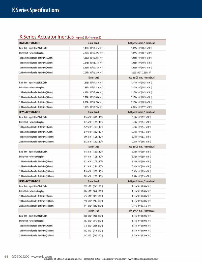
K Series Specifications
64 952.500.6200 | www.exlar.com
K Series Actuator Inertias kg-m2 (lbf-in-sec2)
K60 ACTUATOR 5 mm Lead Add per 25 mm, 5 mm Lead
Base Unit - Input Drive Shaft Only 1.480 x 10⁻⁵ (1.31 x 10⁻⁴) 1.022 x 10⁻⁶ (9.045 x 10⁻⁶)
Inline Unit - w/Motor Coupling 2.702 x 10⁻⁵ (2.39 x 10⁻⁴) 1.022 x 10⁻⁶ (9.045 x 10⁻⁶)
1:1 Reduction Parallel Belt Drive (66 mm) 4.339 x 10⁻⁵ (3.84 x 10⁻⁴) 1.022 x 10⁻⁶ (9.045 x 10⁻⁶)
1:1 Reduction Parallel Belt Drive (86 mm) 7.378 x 10⁻⁵ (6.53 x 10⁻⁴) 1.022 x 10⁻⁶ (9.045 x 10⁻⁶)
1:1 Reduction Parallel Belt Drive (96 mm) 8.564 x 10⁻⁵ (7.58 x 10⁻⁴) 1.022 x 10⁻⁶ (9.045 x 10⁻⁶)
2:1 Reduction Parallel Belt Drive (96 mm) 7.095 x 10⁻⁵ (6.28 x 10⁻⁴) 2.555 x 10⁻⁷ (2.261 x 1-6)
10 mm Lead Add per 25 mm, 10 mm Lead
Base Unit - Input Drive Shaft Only 1.616 x 10⁻⁵ (1.43 x 10⁻⁴) 1.173 x 10⁻⁶ (1.038 x 10⁻⁵)
Inline Unit - w/Motor Coupling 2.837 x 10⁻⁵ (2.51 x 10⁻⁴) 1.173 x 10⁻⁶ (1.038 x 10⁻⁵)
1:1 Reduction Parallel Belt Drive (66 mm) 4.474 x 10⁻⁵ (3.96 x 10⁻⁴) 1.173 x 10⁻⁶ (1.038 x 10⁻⁵)
1:1 Reduction Parallel Belt Drive (86 mm) 7.514 x 10⁻⁵ (6.65 x 10⁻⁴) 1.173 x 10⁻⁶ (1.038 x 10⁻⁵)
1:1 Reduction Parallel Belt Drive (96 mm) 8.704 x 10⁻⁵ (7.70 x 10⁻⁴) 1.173 x 10⁻⁶ (1.038 x 10⁻⁵)
2:1 Reduction Parallel Belt Drive (96 mm) 1.966 x 10⁻⁵ (1.74 x 10⁻⁴) 2.931 x 10⁻⁷ (2.595 x 10⁻⁶)
K75 ACTUATOR 5 mm Lead Add per 25 mm, 5 mm Lead
Base Unit - Input Drive Shaft Only 9.26 x 10⁻⁵ (8.20 x 10⁻⁴) 3.13 x 10⁻⁶ (2.77 x 10⁻⁵)
Inline Unit - w/Motor Coupling 1.25 x 10⁻⁴ (1.11 x 10⁻³) 3.13 x 10⁻⁶ (2.77 x 10⁻⁵)
1:1 Reduction Parallel Belt Drive (86 mm) 2.29 x 10⁻⁴ (2.03 x 10⁻³) 3.13 x 10⁻⁶ (2.77 x 10⁻⁵)
1:1 Reduction Parallel Belt Drive (96 mm) 3.19 x 10⁻⁴ (2.82 x 10⁻³) 3.13 x 10⁻⁶ (2.77 x 10⁻⁵)
1:1 Reduction Parallel Belt Drive (130 mm) 5.96 x 10⁻⁴ (5.28 x 10⁻³) 3.13 x 10⁻⁶ (2.77 x 10⁻⁵)
2:1 Reduction Parallel Belt Drive (130 mm) 2.82 x 10⁻⁴ (2.50 x 10⁻³) 7.83 x 10⁻⁷ (6.93 x 10⁻⁶)
10 mm Lead Add per 25 mm, 10 mm Lead
Base Unit - Input Drive Shaft Only 9.48 x 10⁻⁵ (8.39 x 10⁻⁴) 3.32 x 10⁻⁶ (2.94 x 10⁻⁵)
Inline Unit - w/Motor Coupling 1.44 x 10⁻⁴ (1.28 x 10⁻³) 3.32 x 10⁻⁶ (2.94 x 10⁻⁵)
1:1 Reduction Parallel Belt Drive (86 mm) 2.31 x 10⁻⁴ (2.05 x 10⁻³) 3.32 x 10⁻⁶ (2.94 x 10⁻⁵)
1:1 Reduction Parallel Belt Drive (96 mm) 3.21 x 10⁻⁴ (2.84 x 10⁻³) 3.32 x 10⁻⁶ (2.94 x 10⁻⁵)
1:1 Reduction Parallel Belt Drive (130 mm) 5.98 x 10⁻⁴ (5.30 x 10⁻³) 3.32 x 10⁻⁶ (2.94 x 10⁻⁵)
2:1 Reduction Parallel Belt Drive (130 mm) 2.83 x 10⁻⁴ (2.51 x 10⁻³) 8.30 x 10⁻⁷ (7.36 x 10⁻⁶)
K90 ACTUATOR 5 mm Lead Add per 25 mm, 5 mm Lead
Base Unit - Input Drive Shaft Only 2.97 x 10⁻⁴ (2.63 x 10⁻³) 1.11 x 10⁻⁵ (9.80 x 10⁻⁵)
Inline Unit - w/Motor Coupling 3.84 x 10⁻⁴ (3.40 x 10⁻³) 1.11 x 10⁻⁵ (9.80 x 10⁻⁵)
1:1 Reduction Parallel Belt Drive (96 mm) 5.12 x 10⁻⁴ (4.53 x 10⁻³) 1.11 x 10⁻⁵ (9.80 x 10⁻⁵)
1:1 Reduction Parallel Belt Drive (130 mm) 7.98 x 10⁻⁴ (7.07 x 10⁻³) 1.11 x 10⁻⁵ (9.80 x 10⁻⁵)
2:1 Reduction Parallel Belt Drive (130 mm) 3.41 x 10⁻⁴ (3.02 x 10⁻³) 2.77 x 10⁻⁶ (2.45 x 10⁻⁵)
10 mm Lead Add per 25 mm, 10 mm Lead
Base Unit - Input Drive Shaft Only 3.00 x 10⁻⁴ (2.66 x 10⁻³) 1.13 x 10⁻⁵ (1.00 x 10⁻⁴)
Inline Unit - w/Motor Coupling 3.87 x 10⁻⁴ (3.43 x 10⁻³) 1.13 x 10⁻⁵ (1.00 x 10⁻⁴)
1:1 Reduction Parallel Belt Drive (96 mm) 5.15 x 10⁻⁴ (4.56 x 10⁻³) 1.13 x 10⁻⁵ (1.00 x 10⁻⁴)
1:1 Reduction Parallel Belt Drive (130 mm) 8.02 x 10⁻⁴ (7.10 x 10⁻³) 1.13 x 10⁻⁵ (1.00 x 10⁻⁴)
2:1 Reduction Parallel Belt Drive (130 mm) 3.42 x 10⁻⁴ (3.03 x 10⁻³) 2.82 x 10⁻⁶ (2.50 x 10⁻⁵)
Courtesy of Steven Engineering, Inc. - (800) 258-9200 - [email protected] - www.stevenengineering.com

952.500.6200 | www.exlar.com 65
8000
7000
6000
5000
4000
3000
2000
1000
00 300
(11.8)600
(23.6)900
(35.4)1200(47.2)
RPM
Stroke, mm (inch)
K758000
7000
6000
5000
4000
3000
2000
1000
00 300
(11.8)600
(23.6)900
(35.4)1200(47.2)
RPM
Stroke, mm (inch)
K60
Critical Speed in RPM vs Stroke Length for:
6000
5000
4000
3000
2000
1000
00 300
(11.8)600
(23.6)900
(35.4)1200(47.2)
RPM
Stroke, mm (inch)
K90
Critical Speed in RPM vs Stroke Length:
200(44.9)
160(36.0)
120(27.0)
80(18.0)
40(9.0)
00 300
(11.8)600
(23.6)900
(35.4)1200(47.2)
Stroke, mm (inch)
K75100
(22.5)
80(18.0)
60(13.5)
40(9.0)
20(4.5)
00 300
(11.8)600
(23.6)900
(35.4)1200(47.2)
Stroke, mm (inch)
K60
Maximum Radial Load
600(134.9)
500(112.4)
400(89.9)
300(67.4)
200(44.9)
100(22.5)
00 300
(11.8)600
(23.6)900
(35.4)1200(47.2)
Stroke, mm (inch)
K90N (lbf) N (lbf) N (lbf)
Maximum Radial Load:
12000(2700)
10000(2250)
8000(1800)
6000(1350)
4000(900)
2000(450)
00 300
(11.8)600
(23.6)900
(35.4)1200(47.2)
Stroke, mm (inch)
K757000
(1575)6000
(1350)5000
(1125)4000(900)3000(675)2000(450)1000(255)
00 300
(11.8)600
(23.6)900
(35.4)1200(47.2)
Stroke, mm (inch)
K60
Maximum Force Rating vs Stroke
18000(4045)
14000(3145)
10000(2250)
6000(1350)
2000(450)
00 300
(11.8)600
(23.6)900
(35.4)1200(47.2)
Stroke, mm (inch)
K90N (lbf) N (lbf) N (lbf)
Maximum Force Rating vs Stroke:
––– Critical Speed based on critical speed of the roller screw
- - - Actuator Rated Speed Speed at which we have tested and rated the actuator
* With longer stroke length actuators, the rated speed of the actuator is determined by the critcal speed
K Series Specifications
K S
erie
s
Courtesy of Steven Engineering, Inc. - (800) 258-9200 - [email protected] - www.stevenengineering.com

K60 Dimensions and Motor Mounting Options
66 952.500.6200 | www.exlar.com
Max Allowable Actuator Force = 1350 Pounds
All Dimension shown in mm [inch]
26.041.025
33.001.299
106.30 + Stroke4.185
32.501.280
9.500.374
44.501.752
Ø 10.00 -0.030.00
0.394 - 0.001+0.000
9.500.374
14.000.551
14.500.571
Ø 41.81- 0.050.00
1.646 - 0.002+ 0.000Ø45.00-
0.000.03
60.002.362
27.00°
Ø 56.00 B.C.2.205
Ø M6x1.0 16.00
Ø BA
78.053.073
38.101.500
82.553.250
Ø 6.600.260
9.530.375
101.604.000
39.031.536
10.000.394115.00
4.528
90.003.543
45.001.772
65.002.559
Ø 9.000.354
72.002.835
21.740.856
Ø 6.600.260
25.441.001
90.003.543
3.560.140
Motor Dependent
Motor DependentMotor Dependent
61.312.414
146.005.748
66.002.598
178.507.028
68.492.696
86.003.386
77.663.058
206.008.110
96.003.780
60.002.362
Ø 54.00 B.C.2.126
Ø M6x1.0 16.00
29.00°
K60 Base Actuator
K60 Mounting Accessories (Ordered Separately)
K60 Motor Mounting Options
K60 Parallel Drive (PXX or SXX)
K60 Trunnion Mount (KSST-60, KSMT-60) K60 Foot Mount (KSFM-60)
K60 Front Flange (KSFF-60) K60 End Angles (Base Unit–KSEA-60, Parallel, P10 or S10–KSEP-60)
Non-Std Motor Mount Inch Metric
Shaft Diameter 1/4, 3/16, 3/8, 1/2, 5/8 10, 12, 14, 15, 16
Std Motor Mount Shaft Diameter Shaft LengthM60 14 mm 30 mm
G60 16 mm 36 mm
M90 19 mm 40 mm
N23 0.25" 0.81"
N34 0.5" 1.19"
K60 Inline Intergrated Coupling (ISC) Keyed motor Shaft Recommended for Inline Mount
66 mm wide housing 86 mm wide housing 96 mm wide housing
See table top of page 73 to determine which housing will be mounted to your actuator.
Version Dim “A” Dim “øB”
KSST-60 4.928” 1.000 +/- .001"
KSMT-60 106.88 mm 16.00 -.03 mm/-.07 mm
Courtesy of Steven Engineering, Inc. - (800) 258-9200 - [email protected] - www.stevenengineering.com

K60 Dimensions and Motor Mounting Options
952.500.6200 | www.exlar.com 67
Ø "A""B"
"C"
"D"
"E"
"F" "G"
Clevis and Eye Dimesions, Imperial and Metric
Ø "A""B"
"C"
"D"
"F"
"E" "A"
"C"
"D"
"E""B"
Ø "F"
"B"
"F"
"A" "A"
"A"
"C""D"
Ø "A"
"E"
"B""C" "C"
"A"
Ø "D"
Ø "E"
"E"
"J"
Ø "B"
"F""G"
"C"
"K"
"D"
"A"
"H"
Ø "C"
"F" ThreadDepth "D"
"E"
"A Hex "
"B"
"D"
"B"
Ø "G"
Ø "F"
"D""E"
"D"
"C"
"K""H"
K60 Parallel Only Mounting Options (Ordered Separately)Rear Clevis (KSRC-60, KSMC-60) Rear Eye (KSRE-60, KSME-60) K60 Rear Flange (KSRF-60-66, KSRF-60-86, KSRF-60-96)
K60 Rod End Attachments
K60 Rod Ends
Rod End Option Thread A Hex B ø C Rod D E F
M/W U.S. Male 1/2-20 UNF-2A 1.02" (28.00 mm) .875" (22.2 mm) 1.249" (31.74 mm) 0.472" (12.00 mm) 1.025" (26.04 mm) N/A
F/V U.S. Female 1/2-20 UNF-2B 1.02" (28.00 mm) N/A 1.249” (31.74 mm) 0.472" (12.0 mm) 1.025” (26.04 mm) .75" (19.0 mm)
A/R Metric Male M12 x 1.25 6g 1.02" (28.00 mm) .945" (24 mm) 1.249” (31.74 mm) 0.472" (12.0 mm) 1.025” (26.04 mm) N/A
B/L Metric Female M12 x 1.25 6H 1.02" (28.00 mm) N/A 1.249” (31.74 mm) 0.472" (12.0 mm) 1.025” (26.04 mm) .70" (17.80 mm)
SRM050 Spherical Rod EyeA 2.125" (54.0 mm)
Ø B .500" (12.7 mm)C 1.156" (29.4 mm)D 1.312" (33.3 mm)E 6 DegF .500" (12.7 mm)G .625" (15.9 mm)H .875" (22.2 mm)J .750" (19.1 mm)K 1/2-20
REI50 Rod EyeØ A .50" (12.7 mm)B .75" (19.05 mm)C 1.50" (38.1 mm)D .75" (19.05 mm)E .375" (9.53 mm)F 1/2-20
RCI50 Rod ClevisA .750" (19.05 mm)B .750" (19.05 mm)C 1.500" (38.1 mm)D .500" (12.7 mm)E .765" (19.43 mm)
Ø F .500" (12.7 mm)Ø G 1.000" (25.4 mm)H 1.000" (25.4 mm)
Ø J N/AK 1/2-20
Clevis Pin KSMP-60 CP 050A 2.56" (65 mm) 2.28" (57.9 mm)B 2.19" (55.50 mm) 1.94" (49.28 mm)C .19" (4.75 mm) .17" (4.32 mm)
Ø D .47" (12 mm) .50" (12.7 mm)Ø E .12" (3 mm) .095" (2.41 mm)
Option Dim A Dim B Dim C Dim D Dim E Dim F Dim G
Inch Clevis (KSRC-60)
.500"+.004/+.002 1.500" 1.000" 1.100" 1.500" .750"
+.020/-.0001.750"
+.000/-.029Metric Clevis (KSMC-60)
12 mm+.04/-0 25.00 mm 16.00 mm 24.00 mm 28.00 mm 28.00 mm
+.52/-.0052.00
+.00/-.74 mmInch Eye (KSRE-60)
.500"+.004/+.002 1.125" .750" 1.100" 1.250" .750"
+.008/-.024 NA
Metric Eye (KSME-60)
12 mm+.04/-0 25.00 mm 16.00 mm 24.00 mm 28.00 mm 28.00 mm
+.20/-.60 NA
Option Dim A Dim B Dim C Dim D Dim E Dim F
KSRF-60-66 .394" 10.00 mm
2.559" 65.00 mm
3.543" 90.00 mm
4.528" 115.00 mm
1.772" 45.00 mm
.354" 9.00 mm
KSRF-60-86 .472" 12.00 mm
2.950" 75.00 mm
3.937" 100.00 mm
4.724" 120.00 mm
1.969" 50.00 mm
.354" 9.00 mm
KSRF-60-96 .750" 19.05 mm
3.780" 96.00 mm
4.961" 126.00 mm
6.496"165.00 mm
2.480"63.00 mm
.480"12.2 mm
K S
erie
s
Courtesy of Steven Engineering, Inc. - (800) 258-9200 - [email protected] - www.stevenengineering.com

Max Allowable Actuator Force = 2000 Pounds
All Dimension shown in mm [inch]
33.031.300
Ø 52.00 -0.000.03
37.001.457
133.49 + Stroke5.256
40.501.594 15.00
0.591
19.310.760
51.852.041
Ø 51.94 -0.000.05
Ø 12.00 -0.000.03
17.540.691
12.000.472
28.0°
Ø 68.002.677
B.C.
75.002.953
M8x1.25 16.00
28.0°
Ø 68.002.677
B.C.
M8x1.25 21.50
75.002.953
99.403.913
AØ B
50.001.969
125.004.921
13.000.512
100.003.937
Ø 9.000.354
50.001.969
80.003.150
50.001.969
Ø 9.000.354
100.003.937
130.005.118
15.000.591
50.001.968
75.002.953
6.350.250
50.001.969
Ø 9.000.354 27.50
1.08340.001.575
Motor Dependent
Motor Dependent
Motor Dependent
178.507.028
71.662.821
86.003.386
206.008.110
77.673.058
96.003.780
275.0010.827
90.843.576
130.005.118
68 952.500.6200 | www.exlar.com
K75 Dimensions and Motor Mounting Options
K75 Base Actuator
K75 Mounting Accessories (Ordered Separately)
K75 Motor Mounting Options
K75 Parallel Drive (PXX or SXX)
K75 Trunnion Mount (KSST-75, KSMT-75) K75 Foot Mount (KSFM-75)
K75 Front Flange (KSFF-75) K75 End Angles (Base Unit–KSEA-75, Parallel, P10 or S10–KSEP-75)
Non-Std Motor Mount Inch Metric
Shaft Diameter 1/4, 3/16, 3/8, 1/2, 5/8 10, 12, 14, 15, 16
Std Motor Mount Shaft Diameter Shaft LengthM60 14 mm 30 mmG60 16 mm 36 mmM75 14 mm 30 mmG75 16 mm 30 mmN34 0.5" 0.19"M90 19 mm 40 mmG90 22 mm 48 mm
M115 24 mm 50 mm
K75 Inline Intergrated Coupling (ISC) Keyed motor Shaft Recommended for Inline Mount
86 mm wide housing 96 mm wide housing 130 mm wide housing
See table top of page 73 to determine which housing will be mounted to your actuator.
Version Dim “A” Dim “øB”
KSST-75 5.913" .999 + .000/- .002"
KSMT-75 150.20 mm 19.97 +.00 mm/-.05 mm
Courtesy of Steven Engineering, Inc. - (800) 258-9200 - [email protected] - www.stevenengineering.com

“E"
“C”
“J”
“A”
Ø “B”Ø “D”
“H” “K”
Ø “A”
“C”
“E”
“B”
“D”
“B”
“A”
“D” “D”“E”
“K”
“C”
Ø “F”
Ø “G”
“H”
“F” ThreadDepth
Ø “C”
“D”
“A” Hex
“E”
“B”
“D”
“B”
“C” “C”
Ø “D”
Ø “E”
“A”
"E"
"C"
"D"
Ø "F"
"B"
Ø “A”
“D”
“B”
“C”
“F” “G”
“E”
“B”Ø “A”
“D”
“C”
“F”
“E”
“A”
“F”
“G”
952.500.6200 | www.exlar.com 69
K75 Dimensions and Motor Mounting Options
K75 Parallel Only Mounting Options (Ordered Separately)Rear Clevis (KSRC-75, KSMC-75) Rear Eye (KSRE-75, KSME-75) K75 Rear Flange (KSRF-75-86, KSRF-75-96, KSRF-75-130)
K75 Rod End Attachments
K75 Rod Ends
Rod End Option Thread A Hex B ø C Rod D E F
M/W U.S. Male 3/4-16 UNF-2A 1.18" (30.00 mm) 1.125" (28.58 mm) 1.500" (38.10 mm) 0.551" (14.00 mm) 1.300" (33.03 mm) N/A
F/V U.S. Female 3/4-16 UNF-2B 1.18" (30.00 mm) N/A 1.500" (38.10 mm) 0.551" (14.0 mm) 1.300" (33.03 mm) 1.13" (28.58 mm)
A/R Metric Male M16 x 1.50 6g 1.18" (30.00 mm) 1.125" (32.00 mm) 1.500" (38.10 mm) 0.551" (14.0 mm) 1.300" (33.03 mm) N/A
B/L Metric Female M16 x 1.50 6H 1.18" (30.00 mm) N/A 1.500" (38.10 mm) 0.551" (14.0 mm) 1.300" (33.03 mm) 1.30" (33.00 mm)
SRM075 Spherical Rod EyeA 2.875" (73.03 mm)
Ø B .750" (19.05 mm)C 1.625" (41.28 mm)D 1.500" (38.10 mm)E 14 DegF .688" (17.46 mm)G .875" (22.23 mm)H 1.125" (28.58 mm)J 1.000" (25.40 mm)K 3/4-16
RE075 Rod EyeØ A .750" (19.05 mm)B 1.250" (31.75 mm)C 2.063" (52.39 mm))D 1.125" (28.58 mm)E 3/4-16
RC075 Rod ClevisA 1.125" (28.58 mm)B 1.250" (31.75 mm)C 1.750" (44.45 mm)D .625" (15.88 mm)E 1.265" (32.13 mm)
Ø F .750" (19.05 mm)Ø G 1.500" (38.10 mm)H 1.250" (31.75 mm)
Ø J N/AK 3/4-16
Clevis Pin KSMP-75 KSRP-75A 3.35" (85.0 mm) 3.09" (78.5 mm)B 2.99" (76.0 mm) 2.74" (69.5 mm)C .18" (4.5 mm) .18" (4.5 mm)
Ø D.630" +.000/-.002 (16 mm +.00/-.04)
.750" +.000/-.002(19.05 mm +.00/-.04)
Ø E .14" (3.56 mm) .14"(3.56 mm)
Option Dim A Dim B Dim C Dim D Dim E Dim F Dim G
Inch Clevis (KSRC-75)
.751" +.001/+.000 2.000" 1.375" 1.250" 2.000" 1.251"
+.005/-.001 2.500"
Metric Clevis (KSMC-75)
16 mm +.04 mm/-0 36.00 mm 20.00 mm 30.00 mm 40.00 mm 40.00
+.41/-.00 mm 70.00 mm
Inch Eye (KSRE-75)
.751" +.001/+.000 2.000" 1.375" 1.250" 2.000" 1.250"
+.000/-.005 NA
Metric Eye (KSME-75)
16 mm +.04 mm/-0 36.00 mm 20.00 mm 30.00 mm 34.00 mm 39.80
-.20/-.60 mm NA
Option Dim A Dim B Dim C Dim D Dim E Dim F
KSRF-75-86 .590" 15.00 mm
3.150" 80.00 mm
3.937" 100.00 mm
5.118" 130.00 mm
1.969" 50.00 mm
.354" 9.00 mm
KSRF-75-96 .750" 19.05 mm
3.780" 96.00 mm
4.961" 126.00 mm
6.496" 165.00 mm
2.480" 63.00 mm
.480" 12.20 mm
KSRF-75-130 .750" 19.05 mm
4.370" 111.00 mm
5.906" 150.00 mm
7.323"186.00 mm
2.953"75.00 mm
.561"14.25 mm
K S
erie
s
Courtesy of Steven Engineering, Inc. - (800) 258-9200 - [email protected] - www.stevenengineering.com

70 952.500.6200 | www.exlar.com
K90 Dimensions and Motor Mounting Options
K90 Base Actuator
K90 Mounting Accessories (Ordered Separately)
K90 Motor Mounting Options
K90 Parallel Drive (PXX or SXX)
K90 Trunnion Mount (KSST-90, KSMT-90) K90 Foot Mount (KSFM-90)
K90 Front Flange (KSFF-90) K90 End Angles (Base Unit–KSEA-90, Parallel, P10 or S10–KSEP-90)
Non-Std Motor Mount Inch Metric
Shaft Diameter 1/4, 3/16, 3/8, 1/2, 5/8 10, 12, 14, 15, 16
Std Motor Mount Shaft Diameter Shaft LengthG60 16 mm 36 mmM90 19 mm 40 mmG90 22 mm 48 mmN34 0.5" 1.19"
M115 24 mm 50 mm
K90 Inline Intergrated Coupling (ISC) Keyed motor Shaft Recommended for Inline Mount
96 mm wide housing 130 mm wide housing
See table top of page 73 to determine which housing will be mounted to your actuator.
Version Dim “A” Dim “øB”
KSST-90 6.504" .999 + .000/- .002"
KSMT-90 114.40 mm 19.97 +.00 mm/-.05 mm
Courtesy of Steven Engineering, Inc. - (800) 258-9200 - [email protected] - www.stevenengineering.com

"C"
"D"
Ø "A""B"
"E"
"F" "G"
"B"
"D"
"C"
Ø "A"
"F"
"E"
"A"
"D"
"C"
"B" "E"
Ø "F"
Ø "C"
"F" ThreadDepth
"E"
"D"
"A" Hex
"B""D"
"E"
"C"
"F"
"G"
"J"
"A"
Ø "B"Ø "D"
"H" "K"
Ø "A"
"C"
"E"
"B"
"D"
"B"
"A"
"D" "D""E"
"K"
"C"
Ø "F"
Ø "G"
"H"
"C"
"A"
"B""C"
Ø "E"
Ø "D"
952.500.6200 | www.exlar.com 71
K90 Dimensions and Motor Mounting Options
K90 Parallel Only Mounting Options (Ordered Separately)Rear Clevis (KSRC-90, KSMC-90) Rear Eye (KSRE-90, KSME-90) K90 Rear Flange (KSRF-90-96, KSRF-90-130)
K90 Rod End Attachments
K90 Rod Ends
Rod End Option Thread A Hex B ø C Rod D E F
M/W U.S. Male 3/4-16 UNF-2A 1.34" (34.00 mm) 1.50" (38.10 mm) 1.750" (44.45 mm) 0.629" (16.00 mm) 1.611" (40.91 mm) N/A
F/V U.S. Female 3/4-16 UNF-2B 1.34" (34.00 mm) N/A 1.750" (44.45 mm) 0.629" (16.00 mm) 1.611" (40.91 mm) 1.25" (31.75 mm)
A/R Metric Male M20 x 1.5 6g 1.34" (34.00 mm) 1.417" (36.00 mm) 1.750" (44.45 mm) 0.629" (16.00 mm) 1.611" (40.91 mm) N/A
B/L Metric Female M20 x 1.5 6H 1.34" (34.00 mm) N/A 1.750" (44.45 mm) 0.629" (16.00 mm) 1.611" (40.91 mm) 1.50" (38.10 mm)
SRM090 Spherical Rod EyeA 2.875" (73.03 mm)
Ø B .750" (19.05 mm)C 1.625" (41.28 mm)D 1.500" (38.10 mm)E 14 DegF .688" (17.46 mm)G .875" (22.23 mm)H 1.125" (28.58 mm)J 1.000" (25.40 mm)K 3/4-16
RE090 Rod EyeØ A .750" (19.05 mm)B 1.250" (31.75 mm)C 2.063" (52.39 mm))D 1.125" (28.58 mm)E 3/4-16
RC090 Rod ClevisA 1.125" (28.58 mm)B 1.250" (31.75 mm)C 1.750" (44.45 mm)D .625" (15.88 mm)E 1.265" (32.13 mm)
Ø F .750" (19.05 mm)Ø G 1.500" (38.10 mm)H 1.250" (31.75 mm)
Ø J N/AK 3/4-16
Clevis Pin KSMP-90 KSRP-90A 4.13" (105.0 mm) 4.13" (105.0 mm)B 3.78" (96.0 mm) 3.78" (96 mm)C .18" (4.5 mm) .18" (4.5 mm)
Ø D.630" +.000/-.002 (16 mm +.00/-.04)
.750" +.000/-.002(19.05 mm +.00/-.04)
Ø E .14" (3.56 mm) .14"(3.56 mm)
Option Dim A Dim B Dim C Dim D Dim E Dim F Dim G
Inch Clevis (KSRC-90)
.750" +.001/+.000 2.000" 1.375" 1.450" 2.100" 1.251"
+.005/-.001 3.544"
Metric Clevis (KSMC-90)
16 mm +.04 mm/-0 36.00 mm 20.00 mm 36.00 mm 37.00 mm 50.00
+.41/-.00 mm 90.00 mm
Inch Eye (KSRE-90)
.750" +.001/+.000 2.000" 1.375" 1.450" 2.100" 1.250"
+.000/-.005 NA
Metric Eye (KSME-90)
16 mm +.04 mm/-0 36.00 mm 20.00 mm 36.00 mm 37.00 mm 50.00
-.20/-.60 mm NA
Option Dim A Dim B Dim C Dim D Dim E Dim F
KSRF-90-96 .750" 19.05 mm
3.780" 96.00 mm
4.961" 126.00 mm
6.496" 165.00 mm
2.480" 63.00 mm
.480" 12.20 mm
KSRF-90-130 .750" 19.05 mm
4.370" 111.00 mm
5.906" 150.00 mm
7.323"186.00 mm
2.953"75.00 mm
.561"14.25 mm
K S
erie
s
Courtesy of Steven Engineering, Inc. - (800) 258-9200 - [email protected] - www.stevenengineering.com

K60 K75 K90 Mounting Attachments (including proper number of standard T nuts and screws)
KSRF-60-XX KSRF-75-XX KSRF-90-XX Rear Flange Attachment (see drawings and table on next page)
KSFF-60 KSFF-75 KSFF-90 Front Flange Attachment
KSEA-60 KSEA-75 KSEA-90 End Angles, Stainless Steel Std (includes 2)*
KSEP-60 KSEP-75 KSEP-90 End Angles, Parallel, Stainless Steel Std (includes 2)
KSFM-60 KSFM-75 KSFM-90 Foot Mounts (includes 2)
KSST-60 KSST-75 KSST-90 Side Trunnions (includes 2)
KSRC-60 KSRC-75 KSRC-90 Rear Clevis (includes pins)
KSRE-60 KSRE-75 KSRE-90 Rear Eye
KSMT-60 KSMT-75 KSMT-90 Metric Side Trunnion
KSMC-60 KSMC-75 KSMC-90 Metric Rear Clevis (includes pins)
KSME-60 KSME-75 KSME-90 Metric Rear Eye
K60 K75 K90 Rod End Attachments
SRM050 SRM075 SRM075 Front Spherical Rod Eye, fits “M” and “W” Rod only
REI050 RE075 RE075 Front Rod Eye, fits “M” and “W” Rod only
RC050 RC075 RC075 Front Rod Clevis, fits “M” and “W” Rod only
K60 K75 K90 Clevis Pins
KSRP-60 KSRP-75 KSRP-90 Clevis Pin for Front and Rear Clevis, Rod Eyes and Rod Clevis
KSMP-60 KSMP-75 KSMP-90 Metric Clevis Pin for Rear Metric Clevis, Metric Rod Eyes and Rod Clevis
Limit Switches (if required in addition to L1, L2, L3 option in actuator model)
43404 Normally Closed Limit Switch
43403 Normally Open Limit Switch
Consult your local sales representative to discuss maximum stroke length allowable with your final configuration.Most accessories are available in stainless steel. Consult Exlar for availability and leadtime.* This option restricts max. load to 6.0 KN (1350 lbf ) for K60, 8.9 KN (2000 lbf ) for K75 and 9.3 KN (2100 lbf ) for K90.
K Series™ Accessories
Standard IP Ratings for Exlar ActuatorsThe standard IP rating for Exlar actuators is IP54S or IP65S as defined by the IEC. Ingress protection is divided into two categories; solids and liquids. For example, in IP65 the three digits following “IP” represent different forms of environmental influence:• The first digit represents protection against ingress of solid objects.• The second digit represents protection against ingress of liquids.• The suffix digit represents conditions of motion during the test.
Digit 1 - Ingress of Solid ObjectsThe IP rating system provides for 6 levels of protection against solids.
1 Protected against solid objects over 50mm e.g. hands, large tools.
2 Protected against solid objects over 12.5mm e.g. hands, large tools.
3 Protected against solid objects over 2.5mm e.g. wire, small tools.
4 Protected against solid objects over 1.0mm e.g. wires.
5 Limited protection against dust ingress. (no harmful deposit)
6 Totally protected against dust ingress.
Digit 2 - Ingress of LiquidsThe IP rating system provides for 9 levels of protection against liquids.
1 Protected against vertically falling drops of water or condensation.
2 Protected against falling drops of water, if the case is disposed up to 15 degrees from vertical.
3 Protected against sprays of water from any direction, even if the case is disposed up to 60 degrees from vertical.
4 Protected against splash water from any direction.
5 Protected against low pressure water jets from any direction. Limited ingress permitted.
6 Protected against high pressure water jets from any direction. Limited ingress permitted.
7 Protected against short periods of immersion in water of 1m or less for 30 minutes or less.
8 Protected against long durations of immersion in water.
9 High-pressure, high-temperature wash-down applications.
Suffix
S Device standing still during operation M Device moving during
operation
K Series Specifications
72 952.500.6200 | www.exlar.comCourtesy of Steven Engineering, Inc. - (800) 258-9200 - [email protected] - www.stevenengineering.com

GGG = Motor Mount ProvisionsA## = Alpha numeric motor call out - contact Exlar Applications Engineering Department. Motor not included.NMT = No motor mount - keyed shaft on base unit only N23 = Nema 23 standard dimensionN34 = Nema 34 standard dimensionM60 = Exlar 60 mm SLM, motor not includedM90 = Exlar 90 mm SLM, motor not includedM11 = Exlar 115 mm SLM, motor not includedG60 = Exlar 60 mm SLG, motor not includedG90 = Exlar 90 mm SLG, motor not includedAB2,3 = Rockwell 2 & 3 inch (60 & 80 mm) motorsBD2,3 = Baldor 2 & 3 inch (60 & 80 mm) motorsEM2,3 = Emerson CT Metric 2 & 3 inch
(60 & 80 mm) motorsFA2,3 = Fanuc 2 & 3 inch (60 & 80 mm) motorsIN2,3 = Bosch-Rexroth (Indramat) 2 & 3 inch
(60 & 80 mm) motorsKM2,3 = Danaher 2 & 3 inch (60 & 80 mm) motors MT2,3 = Mitsubishi 2 & 3 inch (60 & 80 mm) motors PC2,3 = Parker 2 & 3 inch (60 & 80 mm) motorsSM2,3 = Siemens 2 & 3 inch (60 & 80 mm) motorsYS2,3 = Yaskawa 2 & 3 inch (60 & 80 mm) motors
The above list is a small representation of the motor options available. Please contact Exlar for additional motor mounting provisions.
X..XX = Travel and Housing Options (Multiple Possible)
SE = Smooth extrusion (no mounting or switch grooves)
EN = Electroless nickel plating of housing parts2 HC = Hard coat anodized, acceptable for food
grade2
X..XX = Travel and Housing Options Cont.WE = White epoxy coating1 PB = Protective bellows for extending rodL1 = One External Limit Switch, channel
mount magnetic sensing prox, N.O.4
L2 = Two External Limit Switches, channel mount magnetic sensing prox, 2 N.C.4
L3 = Three External Limit Switches, channel mount magnetic sensing prox, 1 N.C., 2 N.O.4
L# = External Limit Switches, channel mount magnetic sensing prox4
XH = Special housing option XL = Special lubrication (food grade,
Mobilgrease 28 or other, please specify)
XT = Special travel option
##### = 5 digit part number assigned to designate special model numbers.
Optional 5 digit assigned part number to designate unique model numbers
Notes:1. Recommended only with SE option.2. If special coatings are selected for use in
applications where collection of contaminants is better if avoided, consider use of the SE option for smooth extrusion. This option eliminates the attachment-mounting grooves, and end mounted accessories will be usable with the unit.
3. SS rod end on plated SS rod.4. Not available with SE option.
K Series Ordering Information
Actuator SeriesKX = High Capacity Roller ScrewKM = Standard Capacity Roller ScrewKA = Acme Screw
AA = Actuator Frame Size60 = 60 mm (2.375 inch)75 = 75 mm (2.95 inch)90 = 90 mm (3.54 inch)
BBBB = Stroke Length (mm)0020-1225 mm
CC = Lead (linear motion per screw revolution)05 = 5 mm (0.2 inch) roller screw only10 = 10 mm (0.4 inch) roller screw only01 = 2.54 mm (0.1 inch) acme screw only02 = 5.08 mm (0.2 inch) acme screw only
D = Mounting OptionsN = None, Base Unit
E = Rod OptionsM = Male, US Std threadA = Male Metric threadF = Female US Std threadB = Female Metric thread
FFF = Input Drive ProvisionsNMT = Drive shaft only, no motor mountISC = Inline, includes shaft couplingKeyed Motor Shaft OptionsP10 – Parallel, 1:1 belt reductionP20 = Parallel, 2:1 belt reductionPXX = Custom Ratio, (ex. P13 = 1.3:1 belt reduction)Smooth Motor Shaft OptionsS10 – Parallel, 1:1 belt reductionS20 = Parallel, 2:1 belt reductionSXX = Custom Ratio, (ex. S13 = 1.3:1 belt reduction)
W = Male, US Std thread, SS3
R = Male Metric thread, SS3
V = Female US Std thread, SS3
L = Female Metric thread, SS3
Parallel Mount Housing Width and Rear Flange/Clevis Mount OptionsWhen selecting a parallel mount for your K Series actuator, the table at right indicates what size drive housing will be mounted to your actuator. If your application also requires a rear flange, rear clevis or rear eye, please select the appropriate attachment based on the size of the drive housing.
ActuatorFrame Size
Mounted Motor Frame Size1
Belt ReductionRatio2
Parallel Drive Housing Width3
OptionalRear Flange
OptionalRear Clevis
OptionalRear Eye
K60
60 mm, N23 1:1 66 mm KSRF-60-66KSRC-60 (English) / KSMC-60 (Metric)
KSRE-60 (English) / KSME-60 (Metric)
60 mm, N23 2:1 96 mm KSRF-60-96
90 mm, N34 1:1 or 2:1 96 mm KSRF-60-96
K75
60 mm, N23 1:1 86 mm KSRF-75-86
KSRC-75 (English) / KSMC-75 (Metric)
KSRE-75 (English) / KSME-75 (Metric)
90 mm, N34 1:1 96 mm KSRF-75-96
75 mm, N34 2:1 130 mm KSRF-75-130
115 mm 1:1 130 mm KSRF-75-130
K90
60 or 90 mm 1:1 96 mm KSRF-90-96
KSRC-90 (English) / KSMC-90 (Metric)
KSRE-90 (English) / KSME-90 (Metric)
60 mm, N23 1:1 or 2:1 96 mm KSRF-90-96
90 mm, N34 1:1 or 2:1 130 mm KSRF-90-130
115 mm 1:1 130 mm KSRF-90-130
1 Motor sizes above are based on Exlar’s product offering. Other manufacurers’ motors of comparable size may also be mounted.2 Consult Exlar for special belt reduction ratios.3 See drawings for parallel drive housing dimensions.
K Series Specifications
952.500.6200 | www.exlar.com 73
KAA - BBBB - CC - DE - FFF - GGG - (XX..XX-#####)
K S
erie
s
Courtesy of Steven Engineering, Inc. - (800) 258-9200 - [email protected] - www.stevenengineering.com

74 952.500.6200 | www.exlar.com
FT Series Linear Actuators
FT Series Linear ActuatorsExlar FT Series force tube actuators use a planetary roller screw mounted inside a telescoping tube mechanism. The follower is attached to the moveable force tube, which then extends and retracts as the screw rotates. An external motor (supplied by Exlar or the customer) provides the rotational force.
High PerformanceAs with all of Exlar’s roller screw products, the FT Series actuators deliver heavy load capacity, high speed capabilities, and exceptionally long life when compared to other linear actuator technologies.
Other comparably-sized screw actuator products on the market - specifically ball screw and acme screw actuators - have relatively low load capacities, short working lives and limited speed capabilities. At equivalent sizes, under moderate to heavy loads, it is reasonable to project that FT units will deliver up to 15 times the working life of those other designs. For OEM designers, this often means much more power and durability can be achieved from a much smaller footprint when Exlar FT units are used.
Contamination ProtectionThe FT Series design has all the contamination-isolation advantages of hydraulic cylinders without the limited load, life, and speed of designs built around ball or acme screws. The bearing and roller screw components in the Exlar FT Series force tubes are mounted within the sealed housing. This prevents abrasive particles and other contaminants from entering the actuator’s critical mechanisms, and assures trouble-free operation even in the most severe environments.
FT Series actuators are provided with standard grease lubrication. Custom provisions can be made for oil filled lubrication.
Engineered CompatibilityExlar has removed much of the end-user-engineering burden by designing the FT series to be compatible with a wide variety of standard motors. Motor mounting, actuator mounting, and gearing configurations are available to meet nearly any application’s requirements.
Feature Standard Optional
Long Strokes 6", 12", 18", 24",36", and 48"
Intermediate Lengths up to 96"
Pre-Loaded Follower No Yes
External Limit Switches No One, two or three
Adjustable Switches
Multiple ActuatorMountings
Side Mount, Side Lug, Extended Tie Rods, Rear Clevis, Front Flange, Side
Trunnion, Rear Flange, Front/Rear Flange
Specials Available
Multiple MotorMountingConfigurations
Inline Direct Drive,Parallel 1:1 Drive,
Parallel, 2:1 ReductionSpecials Available
Motors shown in drawings are for illustrative purposes only and are not included with FT Actuators.
74 952.500.6200 | www.exlar.comCourtesy of Steven Engineering, Inc. - (800) 258-9200 - [email protected] - www.stevenengineering.com

FT Series Linear Actuators
Hydraulic cylinder replacementBall screw replacementPneumatic cylinder replacementChip and wafer handlingAutomated flexible fixturingDispensersMachine toolAutomated assemblyParts clampingAutomatic tool changers
Volumetric pumpsMedical equipmentConveyor diverters / gatesPlastics equipmentCut-offsDie cuttersPackaging machineryEntertainmentSawmill equipmentOpen / close doorsFillersFormersPrecision grinders
Indexing stagesLiftsProduct sortingMaterial cuttingMaterial handlingRiveting / fastening / joiningMoldingSemiconductorPick and place systemsRobot manipulator armsSimulatorsPrecision valve control
Ventilation control systemsPressingProcess controlTube bendingWeldingStampingTest standsTension controlWeb guidanceWire windingFood ProcessingDampers
Exlar FT Series Actuators Applications Include:
Motors shown in drawings are for illustrative purposes only and are not included with FT Actuators.
Special Sealing OptionsThe base unit of the FT actuators are sealed at the extending rod end by a rod seal, and on the drive end by a shaft seal (see base unit drawings on pages 80, 82, 84 and 86). These rod and shaft seals, and o-ring sealing provides IP65S sealing for the FT actuator base units.
In standard units with inline or parallel motor mounting, the mounting surface between the actuator and the motor, and between the end cover, or inline cover of the actuator and the actuator housing are not sealed as a standard feature.
These areas of the FT actuators can be sealed as a special option if the environment in which the actuator will be mounted requires the actuator to be sealed. Because of the vast differences in the design of various brands of motors that are mounted to the FT Series actuators, sealing of these two areas may alter the design of the actuator. Please contact your local sales representative for details and quotations on special sealing of this type.
With their high thrust capability, compact size and smooth controlled motion, FT Series actuators are an ideal fit for replacing hydraulics or pneumatics on injection mold toggles. Control improvements from an electromechanical servo system offer less abuse of valuable molds and more consistent performance.
The robust design of the FT series actuator can survive the rugged environment of a sawmill while providing accurate positioning at high rates and with high force.
The smooth and accurate motion of Exlar’s actuators combined with today’s servo
technology make multiple degree of freedom motion simulation applications
easier to implement, cleaner and more efficient than hydraulic solutions.
Food grade & stainless steel FT35 with food grade SLM90 motor
Stainless steel FT35 with stainless steel SLM115 motor
Food grade & stainless steel FT60 with food grade SLG90 motor
952.500.6200 | www.exlar.com 75
FT S
erie
s
Courtesy of Steven Engineering, Inc. - (800) 258-9200 - [email protected] - www.stevenengineering.com

76 952.500.6200 | www.exlar.com
FT Series Linear Actuators
FT Series Lifetime CurvesThe L10 expected life of a roller screw linear actuator is expressed as the linear travel distance that 90% of properly maintained roller screws manufactured are expected to meet or exceed. For higher than 90% reliability, the result should be multiplied by the following factors: 95% x 0.62; 96% x 0.53; 97% x 0.44; 98% x 0.33; 99% x 0.21. This is not a guarantee and these charts should be used for estimation purposes only.
The underlying formula that defines this value is:
Travel life in millions of inches, where:
C = Dynamic load rating (lbf )F = Cubic mean applied load (lbf )S = Roller screw’s lead (inches)
All curves represent properly lubricated and maintained actuators.
6000 (26689)
4000 (17793)
2000 (8896)
0
Travel Life Millions of inches (mm)
Cub
ic M
ean
Loa
d lb
f (N
)
FT35 Actuator
FT 3 5 A ct ua t or
0
2000
4000
6000
1 10 100 1000 10000 100000 1 10 100 1,000 10,000 100,000 (25.4) (254) (2,540) (25,400) (254,000) (2,540,000)
L10
= ( C )3 x S
F
FT35, 45, 60 & 80 High CapacityFT35, 45, 60 & 80 Standard Capacity Shown right are pulley inertias reflected at motor including typical pulleys, belt and standard
bushings. Because of differences in belt and pulley selection due to particular motor choices, please contact your local sales representative if these values are critical to your application.
Standard Inline Coupling Maximum Torque Ratings and Inertia
FT35Torque Rating Inertia
354 lbf-in (40 Nm) 0.000104 kg-m2 (0.000920 lbf-in s2)
FT45Torque Rating Inertia
780 lbf-in (88 Nm) 0.00010743 kg-m2 (0.000951 lbf-in s2)
40000 (177929)
30000 (133447)
20000 (88964)
10000 (44482)
0
Travel Life Millions of inches (mm)
Cub
ic M
ean
Loa
d lb
f (N
)
FT80 Actuator
FT 8 0 A ct ua t or
1 10 100 1,000 10,000 100,000 (25.4) (254) (2,540) (25,400) (254,000) (2,540,000)
Travel Life Millions of inches (mm)
FT45 Actuator
FT45 Actuator
12000 (53379)
10000 (44482)
8000 (35586)
6000 (26689)
4000 (17793)
2000 (8896)
0
Cub
ic M
ean
Loa
d lb
f (N
)
If your application requires high force over a stroke length shorter than the length of the nut, pleasecontact Exlar for derated life calculations. You may also download the article “Calculating Life Expectency” at www.exlar.com/technical_reference_notes
Travel Life Millions of inches (mm)
FT60 Actuator
FT 6 0 A ct ua t or
20000 (88964)
15000 (66723)
10000 (44482)
5000 (22241)
0
Cub
ic M
ean
Loa
d lb
f (N
)
1 10 100 1,000 10,000 100,000(25.4) (254) (2,540) (25,400) (254,000) (2,540,000)
1 10 100 1,000 10,000 100,000 (25.4) (254) (2,540) (25,400) (254,000) (2,540,000)
Courtesy of Steven Engineering, Inc. - (800) 258-9200 - [email protected] - www.stevenengineering.com

952.500.6200 | www.exlar.com 77
FT Series Linear Actuators
1 FT35 actuators with high capacity screw option are 20 mm longer. See dimensions page 80.2 Maximum allowable actuator-generated force that can be applied routinely. Exceeding this force may result in permanent damage to the actuator. For maximum allowable externally-applied axial forces, consult factory. For high force, short stroke applications, consult factory.
FT35 Series Performance Specifications
Model No.
Nominal Frame
Sizein (mm)
Strokein (mm)
Screw Leadin (mm)
Max Force2
lbf (kN)
Linear Speed at Max Rated
RPM in/sec (mm/sec)
Dynamic Load Rating (Std
capacity screw)Ibf (kN)
Dynamic Load Rating (High capacity screw)
Ibf (kN)
Life at Max Force (Std
capacity screw)106 in (Km)
Life at Max Force (High
capacity screw)106 in (Km)
Max Input Torque
Ibf-in (Nm)
Max Rated Input
rpm
Weight BaseIb (kg)
FT35-06053.5(89)
6(152)
0.197 (5)5,000 (22.2)
14.7 (373) 17,800 (79.2) 21,400 (95.2) 8.88 (225.6) 15.4 (392) 196 (22.1)
4,500 30 (14)FT35-0610 0.394 (10) 29.5 (750) 16,500 (73.4) 19,850 (88.3) 14.15 (359.4) 24.6 (626) 392 (44.3)
FT35-0620 0.787 (20) 59.3 (1500) 17,200 (76.5) 20,800 (92.5) 32.05 (814.2) 56.7 (1,440) 783 (88.5)
FT35-12053.5(89)
12(305)
0.197 (5)5,000 (22.2)
14.7 (373) 17,800 (79.2) 21,400 (95.2) 8.88 (225.6) 15.4 (392) 196 (22.1)
4,500 35 (16)FT35-1210 0.394 (10) 29.5 (750) 16,500 (73.4) 19,850 (88.3) 14.15 (359.4) 24.6 (626) 392 (44.3)
FT35-1220 0.787 (20) 59.3 (1500) 17,200 (76.5) 20,800 (92.5) 32.05 (814.2) 56.7 (1,440) 783 (88.5)
FT35-18053.5(89)
18(457)
0.197 (5)5,000 (22.2)
14.7 (373) 17,800 (79.2) 21,400 (95.2) 8.88 (225.6) 15.4 (392) 196 (22.1)
4,500 40 (18)FT35-1810 0.394 (10) 29.5 (750) 16,500 (73.4) 19,850 (88.3) 14.15 (359.4) 24.6 (626) 392 (44.3)
FT35-1820 0.787 (20) 59.3 (1500) 17,200 (76.5) 20,800 (92.5) 32.05 (814.2) 56.7 (1,440) 783 (88.5)
FT35-24053.5(89)
24(610)
0.197 (5)5,000 (22.2)
14.7 (373) 17,800 (79.2) 21,400 (95.2) 8.88 (225.6) 15.4 (392) 196 (22.1)
4,500 45 (21)FT35-2410 0.394 (10) 29.5 (750) 16,500 (73.4) 19,850 (88.3) 14.15 (359.4) 24.6 (626) 392 (44.3)
FT35-2420 0.787 (20) 59.3 (1500) 17,200 (76.5) 20,800 (92.5) 32.05 (814.2) 56.7 (1,440) 783 (88.5)
FT35-36053.5(89)
36(914)
0.197 (5)5,000 (22.2)
8.9 (226) 17,800 (79.2) 21,400 (95.2) 8.88 (225.6) 15.4 (392) 196 (22.1)
2,700 55 (25)FT35-3610 0.394 (10) 17.8 (452) 16,500 (73.4) 19,850 (88.3) 14.15 (359.4) 24.6 (626) 392 (44.3)
FT35-3620 0.787 (20) 35.6 (903) 17,200 (76.5) 20,800 (92.5) 32.05 (814.2) 56.7 (1,440) 783 (88.5)
FT35-48053.5(89)
48 (1219)
0.197 (5)5,000 (22.2)
5.7 (145) 17,800 (79.2) 21,400 (95.2) 8.88 (225.6) 15.4 (392) 196 (22.1)
1,700 65 (30)FT35-4810 0.394 (10) 11.4 (290) 16,500 (73.4) 19,850 (88.3) 14.15 (359.4) 24.6 (626) 392 (44.3)
FT35-4820 0.787 (20) 22.4 (568) 17,200 (76.5) 20,800 (92.5) 32.05 (814.2) 56.7 (1,440) 783 (88.5)
FT35 Reflective Inertias 5 mm Lead 10 mm Lead 20 mm Lead
NMT Unit - J (0)NMT Unit - J (Stroke)
0.00040870.0000159
0.00041210.0000162
0.00042590.0000171
kg-m² (at input shaft)kg-m²/inch of stroke
Inline w/ Coupler - J (0)Inline w/ Coupler - J (Stroke)
0.00051270.0000159
0.00051610.0000162
0.00052990.0000171
kg-m² (at motor shaft)kg-m²/inch of stroke
Parallel 1:1 - J (0)Parallel 1:1 - J (Stroke)
0.00110420.0000159
0.00118550.0000162
0.00144800.0000171
Parallel 2:1 - J (0)Parallel 2:1 - J (Stroke)
0.00140290.0000040
0.00140380.0000040
0.00153450.0000043
*Pulleys for parallel mount match actuator max performance ratings
FT S
erie
s
FT45 Series Performance Specifications
Model No.
Nominal Frame
Sizein (mm)
Strokein (mm)
Screw Leadin (mm)
Max Forcelbf (kN)
Linear Speed at Max Rated
RPM in/sec (mm/sec)
Dynamic Load Rating (Std
capacity screw)Ibf (kN)
Dynamic Load Rating (High capacity screw)
Ibf (kN)
Life at Max Force (Std
capacity screw)106 in (Km)
Life at Max Force (High
capacity screw)106 in (Km)
Max Input Torque
Ibf-in (Nm)
Max Rated Input
rpm
Weight BaseIb (kg)
FT45-0605 4.8(122)
6(152)
0.197 (5) 10,000 (44.5)
11.5 (292) 30650 (136.3) 36800 (163.7) 5.67 (144.0) 9.81 (249.2) 392 (44.1)3,500
57 (26)FT45-0610 0.394 (10) 23.0 (583) 30400 (135.2) 36500 (162.4) 11.06 (280.9) 19.14 (486.3) 783 (88.2)
FT45-1205 4.8(122)
12(305)
0.197 (5) 10,000 (44.5)
11.5 (292) 30650 (136.3) 36800 (163.7) 5.67 (144.0) 9.81 (249.2) 392 (44.1)3,500
68 (31)FT45-1210 0.394 (10) 23.0 (583) 30400 (135.2) 36500 (162.4) 11.06 (280.9) 19.14 (486.3) 783 (88.2)
FT45-1805 4.8(122)
18(457)
0.197 (5) 10,000 (44.5)
11.5 (292) 30650 (136.3) 36800 (163.7) 5.67 (144.0) 9.81 (249.2) 392 (44.1)3,500
79 (36)FT45-1810 0.394 (10) 23.0 (583) 30400 (135.2) 36500 (162.4) 11.06 (280.9) 19.14 (486.3) 783 (88.2)
FT45-2405 4.8(122)
24(610)
0.197 (5) 10,000 (44.5)
11.5 (292) 30650 (136.3) 36800 (163.7) 5.67 (144.0) 9.81 (249.2) 392 (44.1)3,500
90(41)FT45-2410 0.394 (10) 23.0 (583) 30400 (135.2) 36500 (162.4) 11.06 (280.9) 19.14 (486.3) 783 (88.2)
FT45-3605 4.8(122)
36(914)
0.197 (5) 10,000 (44.5)
11.5 (292) 30650 (136.3) 36800 (163.7) 5.67 (144.0) 9.81 (249.2) 392 (44.1)3,500
112 (51)FT45-3610 0.394 (10) 23.0 (583) 30400 (135.2) 36500 (162.4) 11.06 (280.9) 19.14 (486.3) 783 (88.2)
FT45-4805 4.8(122)
48 (1219)
0.197 (5) 10,000 (44.5)
8.2 (208) 30650 (136.3) 36800 (163.7) 5.67 (144.0) 9.81 (249.2) 392 (44.1)2,500
135 (61)FT45-4810 0.394 (10) 16.4 (417) 30400 (135.2) 36500 (162.4) 11.06 (280.9) 19.14 (486.3) 783 (88.2)
FT45 Reflective Inertias 5 mm Lead 10 mm Lead
NMT Unit - J (0)NMT Unit - J (Stroke)
0.0024630.000045
0.0024740.000046
kg-m² (at input shaft)kg-m²/inch of stroke
Inline w/ Coupler - J (0)Inline w/ Coupler - J (Stroke)
0.0025710.000045
0.0025810.000046
kg-m² (at motor shaft)kg-m²/inch of stroke
Parallel 1:1 - J (0)Parallel 1:1 - J (Stroke)
0.0069110.000045
0.0069210.000046
Parallel 2:1 - J (0)Parallel 2:1 - J (Stroke)
0.0034660.000011
0.0034690.000011
*Pulleys for parallel mount match actuator max performance ratings
Intermediate and custom stroke lengths are available. Intermediate leads may also be available. Belt and pulley inertia varies with ratio & motor selection. Please contact your local sales representative. See page 78 for definition of terms.
Courtesy of Steven Engineering, Inc. - (800) 258-9200 - [email protected] - www.stevenengineering.com

78 952.500.6200 | www.exlar.com
FT60 Series Linear Actuators
Max Linear Speed: The linear speed achieved by the actuator at a screw speed equal to the max rotational speed value.
Max Force: Values are derived from the design capacity of the FT actuator and should not be exceeded or relied upon for continuous operation.
Dynamic Load Rating: A design constant used in calculating the estimated travel life of the roller screw. The dynamic mean load is the mean load at which the device will perform one million revolutions.
Torque at Rated Force: The torque required at the screw to produce the force rating.
Screw Inertia: The rotary inertia of the planetary roller screw in the actuator.
Max. Rot. Speed: The maximum allowable rotational screw speed determined by the screw length or the rotational speed limit of the roller screw nut.
Intermediate and custom stroke lengths are also available. Intermediate leads may also be available. Belt and pulley inertia varies with ratio and motor selection.
* Maximum allowable actuator-generated force that can be applied routinely. Exceeding this force may result in permanent damage to the actuator. For maximumallowable externally-applied axial forces, consult factory. For high force, short stroke applications, consult factory.
DEFINITIONS:
Shown right are pulley inertias reflected at motor including typical pulleys, belt and standard bushings. Because of differences in belt and pulley selection due to particular motor choices, please contact your local sales representative if these values are critical to your application.
FT60 Reflective Inertias
6 mm Lead 12 mm Lead 30 mm Lead
NMT Unit - J (0)NMT Unit - J (Stroke)
0.0078464 0.0002539
0.0078709 0.0002547
0.0080424 0.0002600
kg-m²(at input shaft)kg-m²/inch of stroke
Inline w/ Coupler - J (0)Inline w/ Coupler - J (Stroke)
0.0081764 0.0002539
0.0082009 0.0002547
0.0083724 0.0002600
kg-m²(at motor shaft)kg-m²/inch of stroke
Parallel 1:1 - J (0)Parallel 1:1 - J (Stroke)
0.0129357 0.0002539
0.0146113 0.0002547
0.0312682 0.0002600
Parallel 2:1 - J (0)Parallel 2:1 - J (Stroke)
0.0049158 0.0000635
0.0057202 0.0000637
0.0214777 0.0000650
*Pulleys for parallel mount match actuator max performance ratings
Standard Inline Coupling Maximum Torque Ratings and Inertia
FT60Torque Rating Inertia
885 lbf-in (100 N-m) 0.000330 kg-m2 (0.002921 lbf-in s2)
FT60 Series Performance Specifications
Model No.
Nominal Frame
Sizein (mm)
Strokein (mm)
Screw Lead
in (mm)Max Force*
lbf (kN)
Linear Speed at Max Rated
RPM in/sec (mm/sec)
Dynamic Load Rating (Std capacity
screw)Ibf (kN)
Dynamic Load Rating (High capacity screw)
Ibf (kN)
Life at Max Force (Std
capacity screw)106 in (Km)
Life at Max Force (High
capacity screw)106 in (Km)
Max Input Torque
Ibf-in (Nm)
Max Rated Input
rpm
Weight BaseIb (kg)
FT60-12066.0
(152)12
(305)
0.236 (6)20,000 (89.0)
7.9 (201) 51,900 (230.9) 57,933 (257.7) 4.1 (104.8) 5.7 (145.8) 940 (106)
2000100 (45)
FT60-1212 0.472 (12) 15.8 (401) 44,600 (198.4) 49,750 (221.3) 5.2 (133.1) 7.3 (184.7) 1880 (212)
FT60-1230 1.181 (30) 39.0 (1000) 41,700 (185.5) 63,958 (284.5) 10.7 (271.9) 38.6 (981.1) 4699 (531)
FT60-24066.0
(152)24
(610)
0.236 (6)20,000 (89.0)
7.9 (201) 51,900 (230.9) 57,933 (257.7) 4.1 (104.8) 5.7 (145.8) 940 (106)
2000130 (59)
FT60-2412 0.472 (12) 15.8 (401) 44,600 (198.4) 49,750 (221.3) 5.2 (133.1) 7.3 (184.7) 1880 (212)
FT60-2430 1.181 (30) 39.0 (1000) 41,700 (185.5) 63,958 (284.5) 10.7 (271.9) 38.6 (981.1) 4699 (531)
FT60-36066.0
(152)36
(914)
0.236 (6)20,000 (89.0)
7.9 (201) 51,900 (230.9) 57,933 (257.7) 4.1 (104.8) 5.7 (145.8) 940 (106)
2000160 (72)
FT60-3612 0.472 (12) 15.8 (401) 44,600 (198.4) 49,750 (221.3) 5.2 (133.1) 7.3 (184.7) 1880 (212)
FT60-3630 1.181 (30) 39.0 (1000) 41,700 (185.5) 63,958 (284.5) 10.7 (271.9) 38.6 (981.1) 4699 (531)
FT60-48066.0
(152)48
(1219)
0.236 (6)20,000 (89.0)
7.9 (201) 51,900 (230.9) 57,933 (257.7) 4.1 (104.8) 5.7 (145.8) 940 (106)
2000190 (86)
FT60-4812 0.472 (12) 15.8 (401) 44,600 (198.4) 49,750 (221.3) 5.2 (133.1) 7.3 (184.7) 1880 (212)
FT60-4830 1.181 (30) 39.0 (1000) 41,700 (185.5) 63,958 (284.5) 10.7 (271.9) 38.6 (981.1) 4699 (531)
Courtesy of Steven Engineering, Inc. - (800) 258-9200 - [email protected] - www.stevenengineering.com

952.500.6200 | www.exlar.com 79
FT80 Series Linear Actuators
Intermediate and custom stroke lengths are also available. Intermediate leads may also be available. Belt and pulley inertia varies with ratio and motor selection. Please contact your local sales representative. See page78 for definitions of terms.
* Maximum allowable actuator-generated force that can be applied routinely. Exceeding this force may result in permanent damage to the actuator. For maximumallowable externally-applied axial forces, consult factory. For high force, short stroke applications, consult factory.
FT Series Mechanical SpecificationsModel No. FT35, FT45, FT60, FT80
Roller Screw Backlash in (mm) 0.0004 - 0.001 (0.01 - 0.03)
System Backlash* in (mm) 0.002 (0.06)
Standard Lead Accuracy** in/ft (mm/300mm) 0.001 (0.025)
Friction Torque Values lbf* in (nm) FT35: 7.0 (0.79) FT45: 11.0 (1.24) FT60: 14.0 (1.58) FT80: 35.0 (3.95)
Maximum Allowable Side Load See chart pg 88
Environmental Rating (Base Unit Only)*** IP65S Standard
Case:Standard Optional
Epoxy-coated aluminumFood Grade Coating
* System backlash will be different with various types of motor mounting arrangements and couplings. Please discuss your particular configuration with your local sales representative.
** Optional lead accuracy – from 0.0002 in/ft (6 μm/300 mm) to 0.002 in/ft (200 μm/10000 mm) – are also available.
*** For IP65S scaling of unit with motor mounted, Please contact your local sales representative.
Shown right are pulley inertias reflected at motor including typical pulleys, belt and standard bushings. Because of differences in belt and pulley selection due to particular motor choices, please contact your local sales representative if these values are critical to your application.
FT80 Reflective Inertias
6 mm Lead 12 mm Lead 30 mm Lead
NMT Unit - J (0)NMT Unit - J (Stroke)
0.0302504 0.0008022
0.0303275 0.0008035
0.0308673 0.0008124
kg-m²(at input shaft)kg-m²/inch of stroke
Inline w/ Coupler - J (0)Inline w/ Coupler - J (Stroke)
0.0314604 0.0008022
0.0315375 0.0008035
0.0320773 0.0008124
kg-m²(at motor shaft)kg-m²/inch of stroke
Parallel 1:1 - J (0)Parallel 1:1 - J (Stroke)
0.0721056 0.0008022
0.0535533 0.0008035
0.1342578 0.0008124
Parallel 2:1 - J (0)Parallel 2:1 - J (Stroke)
0.0198765 0.0002006
0.0270490 0.0002009
0.0753395 0.0002031
*Pulleys for parallel mount match actuator max performance ratings
Standard Inline Coupling Maximum Torque Ratings and Inertia
FT80Torque Rating Inertia
1770 lbf-in (200 N-m) 0.0001210 kg-m2 (0.010709 lbf-in s2)
FT80 Series Performance Specifications
Model No.
Nominal Frame
Sizein (mm)
Strokein (mm)
Screw Lead
in (mm)Max Force*
lbf (kN)
Linear Speed at Max Rated
RPM in/sec (mm/sec)
Dynamic Load Rating (Std
capacity screw)Ibf (kN)
Dynamic Load Rating (High capacity screw)
Ibf (kN)
Life at Max Force (Std
capacity screw)106 in (Km)
Life at Max Force (High
capacity screw)106 in (Km)
Max Input Torque
Ibf-in (Nm)
Max Rated Input
rpm
Weight BaseIb (kg)
FT80-12068.0
(203)12
(305)
0.236 (6)40,000(177.9)
6.9 (175) 80,700 (359) 94,330 (419.6) 1.94 (49.3) 3.1 (78.7) 1,880 (212)
1750190(86)
FT80-1212 0.472 (12) 13.8 (351) 70,200 (312.2) 84,079 (374) 2.55 (64.9) 4.4 (111.4) 3,760 (425)
FT80-1230 1.181 (30) 34.4 (875) 64,700 (287.8) 95,971 (426.9) 5.00 (127) 16.3 (414.3) 9,399 (1,062)
FT80-24068.0
(203)24
(610)
0.236 (6)40,000(177.9)
6.9 (175) 80,700 (359) 94,330 (419.6) 1.94 (49.3) 3.1 (78.7) 1,880 (212)
1750265
(120)FT80-2412 0.472 (12) 13.8 (351) 70,200 (312.2) 84,079 (374) 2.55 (64.9) 4.4 (111.4) 3,760 (425)
FT80-2430 1.181 (30) 34.4 (875) 64,700 (287.8) 95,971 (426.9) 5.00 (127) 16.3 (414.3) 9,399 (1,062)
FT80-36068.0
(203)36
(914)
0.236 (6)40,000(177.9)
6.9 (175) 80,700 (359) 94,330 (419.6) 1.94 (49.3) 3.1 (78.7) 1,880 (212)
1750340
(153)FT80-3612 0.472 (12) 13.8 (351) 70,200 (312.2) 84,079 (374) 2.55 (64.9) 4.4 (111.4) 3,760 (425)
FT80-3630 1.181 (30) 34.4 (875) 64,700 (287.8) 95,971 (426.9) 5.00 (127) 16.3 (414.3) 9,399 (1,062)
FT80-48068.0
(203)48
(1219)
0.236 (6)40,000(177.9)
6.9 (175) 80,700 (359) 94,330 (419.6) 1.94 (49.3) 3.1 (78.7) 1,880 (212)
1750415
(187)FT80-4812 0.472 (12) 13.8 (351) 70,200 (312.2) 84,079 (374) 2.55 (64.9) 4.4 (111.4) 3,760 (425)
FT80-4830 1.181 (30) 34.4 (875) 64,700 (287.8) 95,971 (426.9) 5.00 (127) 16.3 (414.3) 9,399 (1,062)
FT S
erie
s
Courtesy of Steven Engineering, Inc. - (800) 258-9200 - [email protected] - www.stevenengineering.com

80 952.500.6200 | www.exlar.com
FT35 Series Linear Actuators
3.6392.1
1.6942.9
9.1232
+ STROKE*
0.6215.7
0.051.3
1.5038.1
2.0852.8
1.4536.8
Ø 0.748 +-0.00000.0005
19.0 -0.0000.013
3/8-16 UNC-2A
0.138 +-0.0040.000
3.5 + 0.10.0
Ø 3.860 B.C.
Ø 3.0076.2
0.236 --0.0000.002
6.0 --0.0120.042
5.18131.6
9.60243.8
3.6392.1 1.00
25.4
1.6942.9
9.1232
+ STROKE* 6.3159
2.050
1.5038.1
Ø 1.000 +-0.002**0.001
25.4 +-0.050.03
1.5238.5
0.7419
5.18131.6
9.60243.8
3.6392.1
5.8146
4.75120.7
2.5063.5Ø 0.53
13.5
Ø 0.375 +-0.0010.000
9.53 + 0.030.00
1.6942.9
0.6315.9 9.1
232+ STROKE* 4.19
106.3
1.9649.8
9.60243.8
5.18131.6
3.6392.1
1.6942.9
9.1232
+ STROKE* 4.13104.8
0.6315.9
1.9649.8
2.5063.5
7.50190.5
6.50165.1
3.5088.9
Ø 0.5313.5
Drawings subject to change. Consult Exlar for certified drawings.
FT35 Base ActuatorAll dimensions shown in inches with millimeter equivalent in brackets.
See rod ends for rod end thread details.
* Add 20mm if choosing high capacity option.
FT35 Clevis MountParallel motor mount shown.
All dimensions shown in inches with millimeter equivalent in brackets.
See rod ends for rod end thread details.
Motor plate and cover dimensions are subject to change depending on the motor and ratio selection.* Add 20mm if choosing high capacity option.
** If “G” metric clevis option, Ø 27 mm + 0.00 / - 0.06
FT35 Front Flange MountParallel motor mount shown.
All dimensions shown in inches with millimeter equivalent in brackets.
See rod ends for rod end thread details.
Motor plate and cover dimensions are subject to change depending on the motor and ratio selection.
* Add 20mm if choosing high capacity option.
FT35 Rear Flange MountParallel motor mount shown.
All dimensions shown in inches with millimeter equivalent in brackets.
See rod ends for rod end thread details.
Motor plate and cover dimensions are subject to change depending on the motor and ratio selection.* Add 20mm if choosing high
capacity option.
Courtesy of Steven Engineering, Inc. - (800) 258-9200 - [email protected] - www.stevenengineering.com

952.500.6200 | www.exlar.com 81
FT35 Series Linear Actuators
5.18131.6
9.60243.8
3.6392.1
5.12130.1
7.12180.9
1.0025.4
1.9649.8
1.6942.9
Ø 1.500 ±0.001**38.1 ±0.03
Ø 2.0050.8
STROKE 9.1232
+ STROKE* 4.19106.3
9.60243.8
5.18131.6
3.6392.1
Ø 3.8698.0
B.C.
Ø 3.000 +-0.0000.002
76.20 -0.000.05
1.6942.9
1.2531.8
9.1232
+ STROKE*
1.9649.8
4.19106.3
3/8-16 UNC-2A
9.60243.8
5.18131.6
3.6392.1
0.7519.1
1.6942.9
0.194.8
2.5665.1
Ø 0.4110.3
6.25158.8
5.25133.4
0.5012.7
1.0025.4 9.1
232+ STROKE*
6.50165.1
7.50190.5
9.60243.8
5.18131.6
3.6392.1
3.6392.1
1.8146.0
1.6942.9
9.1232
+ STROKE* 4.19106.3
1.8146.1
0.318
9.1232
+ STROKE*
1.6341.3
Ø .2500+-0.0000**0.0005
.400 [10.2]1/4-20 UNC -2B**
.63
FT35 Trunnion MountParallel motor mount shown.
All dimensions shown in inches with millimeters equivalents in brackets.
See rod ends for rod end thread details.
Motor plate and cover dimensions are subject to change depending on the motor and ratio selection.
* Add 20mm if choosing high capacity option.** If “Q” metric side trunnion option, Ø 35 mm h7
FT35 Extended Tie Rod MountParallel motor mount shown.
All dimensions shown in inches with millimeters equivalents in brackets.
See rod ends for rod end thread details.
Motor plate and cover dimensions are subject to change depending on the motor and ratio selection.
* Add 20mm if choosing high capacity option.
FT35 Side Lug MountParallel motor mount shown.
All dimensions shown in inches with millimeters equivalents in brackets.
See rod ends for rod end thread details.
Motor plate and cover dimensions are subject to change depending on the motor and ratio selection.
* Add 20mm if choosing high capacity option.
FT35 Side MountParallel motor mount shown.
All dimensions shown in inches with millimeters equivalents in brackets.
See rod ends for rod end thread details.
Motor plate and cover dimensions are subject to change depending on the motor and ratio selection.
* Add 20mm if choosing high capacity option.
Drawings subject to change. Consult Exlar for certified drawings.
** If “J” or “K” metric side mount options, M6 x 1.0 9 mm with Ø 6 mm M7 9 mm Dowel Hole
FT S
erie
s
Courtesy of Steven Engineering, Inc. - (800) 258-9200 - [email protected] - www.stevenengineering.com

4.80122.0
1.9950.5
13.9 [354] + STROKE
0.7218.3
Ø 3.1580.00
Ø 1.102 +-0.00000.0005
28.00 -0.0000.0132.73
69.3
Ø 5.236133.00
B.C.
4X M12X1.75 - 6H1.0 26
1.9950.5
13.9 [354] + STROKE9.0229
2.1253.8
Ø 1.378 ±0.00135.00 ±0.03
3.178
R1.435
2.0351.6
1.025
7.9201
1.2632.0
Ø 0.787 H9
20.00 H9
0.615
3.178
0.615
1.1830.0
3.8297.0
5.00127.0
7.48190.0
6.38161.97.63193.7
Ø 0.6917.5
Ø 0.500 +-0.0010.000
12.70 +0.030.00
1.9950.5
13.9 [354] + STROKE
14.55369.5
3.0577.51.00
25.4
7.48190.0
10.83275.0
6.00152.4
9.45240.0
2.4863.1
Ø 0.6917.5
Ø0.472 +-0.0010.000
12.00 +0.030.00
1.9950.5
13.9 [354] + STROKE
14.55369.5
3.0577.5
6.26159.0
1.0025.4
14.55369.5
7.48190.0
82 952.500.6200 | www.exlar.com
FT45 Series Linear Actuators
Drawings subject to change. Consult Exlar for certified drawings.
FT45 Base ActuatorAll dimensions shown in inches with millimeter equivalent in brackets.
See rod ends for rod end thread details.
FT45 Clevis MountParallel motor mount shown.
All dimensions shown in inches with millimeter equivalent in brackets.
See rod ends for rod end thread details.
Motor plate and cover dimensions are subject to change depending on the motor and ratio selection.
FT45 Front Flange MountParallel motor mount shown.
All dimensions shown in inches with millimeter equivalent in brackets.
See rod ends for rod end thread details.
Motor plate and cover dimensions are subject to change depending on the motor and ratio selection.
FT45 Rear Flange MountParallel motor mount shown.
All dimensions shown in inches with millimeter equivalent in brackets.
See rod ends for rod end thread details.
Motor plate and cover dimensions are subject to change depending on the motor and ratio selection.
Option C = Imperial
Option Q = Metric
Courtesy of Steven Engineering, Inc. - (800) 258-9200 - [email protected] - www.stevenengineering.com

952.500.6200 | www.exlar.com 83
FT45 Series Linear Actuators
FT45 Trunnion MountParallel motor mount shown.
All dimensions shown in inches with millimeters equivalents in brackets.
See rod ends for rod end thread details.
Motor plate and cover dimensions are subject to change depending on the motor and ratio selection.
FT45 Extended Tie Rod MountParallel motor mount shown.
All dimensions shown in inches with millimeters equivalents in brackets.
See rod ends for rod end thread details.
Motor plate and cover dimensions are subject to change depending on the motor and ratio selection.
*If “M” metric extended tie rod option, M12 x 1.75-6g
FT45 Side Lug MountParallel motor mount shown.
All dimensions shown in inches with millimeters equivalents in brackets.
See rod ends for rod end thread details.
Motor plate and cover dimensions are subject to change depending on the motor and ratio selection.
Drawings subject to change. Consult Exlar for certified drawings.
FT S
erie
s
4.80122.0
8.30210.9
1.7544.5
Ø 1.750 +-0.0000.002
44.45 -0.000.05
1.9950.5
2.7369.3
1.1529.2
2.2256.4
7.95202.0
1.5740.0
4.80122.0 Ø 1.969 +
-0.0000.002
50.00 -0.000.05
1.1529.2
13.9 [354] + STROKE
1.9950.5
2.7369.3
2.2256.4
7.48190.0
Ø 5.236133.00
B.C.Ø 3.937100.00
1.9950.5
13.9 [354] + STROKE
14.55369.5
3.0577.5
2.359
0.8822.4
1/2-13 UNC*
7.48190.0
3.6693.0
1.2632.0
8.50215.9
1.9950.5
13.9 [354] + STROKE
14.55369.5
3.0577.5
5.26133.6
1.1428.9
1.7745.0
10.77 [273.6] + STROKE
2.0351.6
Ø 0.5313.5
Ø 0.472 +-0.0010.000
12.00 +0.030.00
Imperial Options:A=Front Trunnion Mount 2=Rear Trunnion Mount
13.9 [354] + STROKE
Metric Options:V=Front Trunnion Mount P=Rear Trunnion Mount
Courtesy of Steven Engineering, Inc. - (800) 258-9200 - [email protected] - www.stevenengineering.com

84 952.500.6200 | www.exlar.com
FT60 Series Linear Actuators
FT60 Base ActuatorAll dimensions shown in inches with millimeter equivalent in brackets.
See rod ends for rod end thread details.
FT60 Clevis MountParallel motor mount shown.
All dimensions shown in inches with millimeter equivalent in brackets.
See rod ends for rod end thread details.
Motor plate and cover dimensions are subject to change depending on the motor and ratio selection.
* If “G” metric clevis option, Ø 45 mm + 0.00 / - 0.08
FT60 Front Flange MountParallel motor mount shown.
All dimensions shown in inches with millimeter equivalent in brackets.
See rod ends for rod end thread details.
Motor plate and cover dimensions are subject to change depending on the motor and ratio selection.
FT60 Rear Flange MountParallel motor mount shown.
All dimensions shown in inches with millimeter equivalent in brackets.
See rod ends for rod end thread details.
Motor plate and cover dimensions are subject to change depending on the motor and ratio selection.
6.38161.9
2.2557.1
15.3389
+ STROKE
0.8321.1
0.102.5
2.4161.2
2.0050.7
1.6040.5
Ø 1.378 +-0.00000.0006
35.0 -0.0000.016
9/16-12 UNC-2A 0.197 +-0.0080.000
5.0 + 0.20.0
0.3937 --0.00060.0020
10.0 --0.0150.051
Ø 6.79 [172.4] B.C.
Ø 5.00127.0
15.55395.0
8.53216.7
6.38161.9
2.1354.0
2.2557.1
15.3388
+ STROKE 9.0229
2.5063.5
3.4387.1
Ø 1.750 +-0.002*0.001
44.45 +-0.050.03
2.5163.9
1.25
31.8
6.82173.2
14.32363.7
6.38161.9
8.32211.2
10.00
254.0
4.57116.2
Ø 0.501 +-0.0010.000
12.7 + 0.030.00
Ø 0.6616.7
2.2557.1
1.0025.4
15.3388
+ STROKE 4.6116
3.1981.0
15.55395.0
6.38161.9
8.53216.7
13.00330.2
2.2557.1
15.3388
+ STROKE 5.50139.7
1.0025.4
3.4387.1
6.38161.9
11.00279.4
4.58116.2
Ø 0.501 +-0.0010.000
12.7 +
0.030.00
Ø 0.6616.7
Drawings subject to change. Consult Exlar for certified drawings.
Courtesy of Steven Engineering, Inc. - (800) 258-9200 - [email protected] - www.stevenengineering.com

952.500.6200 | www.exlar.com 85
FT60 Series Linear Actuators
14.32363.7
6.82173.2
6.38161.9
8.13206.4
12.13308.0
2.0050.8
2.25
57.1
STROKE
3.1981.0
15.3388
+ STROKE 4.57116.1
Ø 2.500 ±0.001*63.50 ±0.03
Ø 3.5088.9
14.32363.7
6.82173.2
6.38161.9
Ø 6.79172.4
B.C.
Ø 5.000 +-0.0000.002
127.0 -0.000.05
2.2557.1
2.0050.8
15.3388
+ STROKE 4.57116.1
3.1981.0
9/16-12 UNC-2A
14.32363.7
6.82173.2
6.38161.9
4.19106.4
1.0025.4
2.2557.1
0.5012.7
10.00254.0
8.50215.9
Ø 0.5313.5
2.0050.8
1.0025.4
15.3388
+ STROKE 4.08103.7
14.32363.7
6.82173.2
6.38161.9
2.2557.1
15.3388
+ STROKE 4.57116.1
3.1981.0
0.5012.7
15.3388
+ STROKE
2.5063.5
1/2-13 UNC* 1.13 28.6 Ø .5000 +
-0.0000*0.0005
1.00 [25.4]
FT60 Trunnion MountParallel motor mount shown.
All dimensions shown in inches with millimeters equivalents in brackets.
See rod ends for rod end thread details.
Motor plate and cover dimensions are subject to change depending on the motor and ratio selection.
* If “Q” metric side trunnion option, Ø 60 mm h9
FT60 Extended Tie Rod MountParallel motor mount shown.
All dimensions shown in inches with millimeters equivalents in brackets.
See rod ends for rod end thread details.
Motor plate and cover dimensions are subject to change depending on the motor and ratio selection.
FT60 Side Lug MountParallel motor mount shown.
All dimensions shown in inches with millimeters equivalents in brackets.
See rod ends for rod end thread details.
Motor plate and cover dimensions are subject to change depending on the motor and ratio selection.
FT60 Side MountParallel motor mount shown.
All dimensions shown in inches with millimeters equivalents in brackets.
See rod ends for rod end thread details.
Motor plate and cover dimensions are subject to change depending on the motor and ratio selection.
Drawings subject to change. Consult Exlar for certified drawings.
* If “J” or “K” metric side mount options, M12 x 1.75 19 mm with Ø 12 mm M7 12 mm Dowel Hole
FT S
erie
s
Courtesy of Steven Engineering, Inc. - (800) 258-9200 - [email protected] - www.stevenengineering.com

86 952.500.6200 | www.exlar.com
FT80 Series Linear Actuators
FT80 Base ActuatorAll dimensions shown in inches with millimeter equivalent in brackets.
See rod ends for rod end thread details.
FT80 Front Flange MountParallel motor mount shown.
All dimensions shown in inches with millimeter equivalent in brackets.
See rod ends for rod end thread details.
Motor plate and cover dimensions are subject to change depending on the motor and ratio selection.
FT80 Extended Tie Rod MountParallel motor mount shown.
All dimensions shown in inches with millimeter equivalent in brackets.
See rod ends for rod end thread details.
Motor plate and cover dimensions are subject to change depending on the motor and ratio selection.
8.50215.9
3.0377.0
19.8503
+ STROKE
0.9022.9
0.102.5
3.34
84.7
2.0050.7
1.4837.5
Ø 2.362 +-0.00000.0005
60.0 -0.0000.013
3/4-10 UNC-2A
0.278 +-0.0050.000
7.0 + 0.10.0
0.709 --0.0010.002
18.0 --0.0180.061
Ø 9.33237.0
B.C.
8.78223.0
Ø 6.75171.5
8.77222.8
17.33440.2
8.50215.9
12.75323.9
10.75273.1
6.00152.4
Ø 0.7819.8
Ø 0.625 +-0.0010.000
15.9 + 0.0250.000
3.0377.0
1.2531.8
19.8503
+ STROKE 6.43163.3
4.40111.8
17.33440.2
8.77222.8
8.50215.9
Ø9.33 B.C.[237.0]
Ø 6.75+-0.0000.002
171.45 -0.000.05
3.0377.0
3.5088.9
19.8503
+ STROKE 6.43163.3
4.40111.8
3/4-10 UNC-2A
Drawings subject to change. Consult Exlar for certified drawings.
Courtesy of Steven Engineering, Inc. - (800) 258-9200 - [email protected] - www.stevenengineering.com
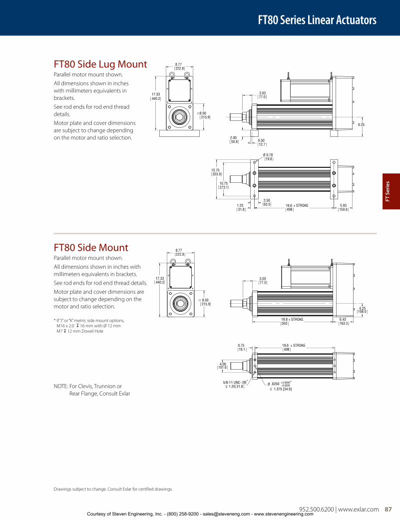
952.500.6200 | www.exlar.com 87
FT80 Series Linear Actuators
17.33440.2
8.50215.9
8.77222.8
6.25
3.0377.0
2.0050.8 0.50
12.7
1.2531.8
Ø 0.7819.8
10.75273.1
12.75323.9
2.5063.5 19.6
498+ STROKE 5.93
150.6
8.77222.8
17.33440.2
8.50215.9
3.0377.0
19.8503
+ STROKE
4.25108.0
6.43163.3
4.00101.6
0.7519.1
19.6498
+ STROKE
Ø .6250 +-
0.0000*0.0005
1.375 [34.9]
5/8-11 UNC -2B* 1.25 31.8
FT80 Side Lug MountParallel motor mount shown.
All dimensions shown in inches with millimeters equivalents in brackets.
See rod ends for rod end thread details.
Motor plate and cover dimensions are subject to change depending on the motor and ratio selection.
FT80 Side MountParallel motor mount shown.
All dimensions shown in inches with millimeters equivalents in brackets.
See rod ends for rod end thread details.
Motor plate and cover dimensions are subject to change depending on the motor and ratio selection.
NOTE: For Clevis, Trunnion or Rear Flange, Consult Exlar
Drawings subject to change. Consult Exlar for certified drawings.
* If “J” or “K” metric side mount options, M16 x 2.0 16 mm with Ø 12 mm M7 12 mm Dowel Hole
FT S
erie
s
Courtesy of Steven Engineering, Inc. - (800) 258-9200 - [email protected] - www.stevenengineering.com

88 952.500.6200 | www.exlar.com
Rod Ends
FT Series Max. Allowable Side Load
FT Series Linear Actuators
Case Dimensions
3.310
3.310
R0.0375
0.075
0.138
T-Slot Detail
0.270
0.426
0.645
7.900
7.900
1.173
FT35
6.024
6.024
0.609
FT60
FT80
SEE T-SLOT DETAIL
See T-Slot Detail
SEE T-SLOT DETAIL
FT45
4.646
4.646
4X SensorGroove
0.260.21
0.070.22
Detail 4X Sensor Groove
A
B DøC
øE
ThreadThread
øE
D
F
Ain (mm)
Bin (mm)
ØCin (mm)
Din (mm)
ØEin (mm)
Fin (mm)
MaleU.S.
Male Metric
Female U.S.
Female Metric
FT60 2.00 (50.8)
2.750 (69.9)
2.360 (59.9)
0.750 (19.1)
3.000 (76.2)
2.000 (50.8)
1 7/8-12 UN-2A
M42x4.56g
1 7/8-12 UN-2B
M42x4.56h
FT80 2.75 (69.9)
4.019 (102.1)
3.143 (79.8)
1.000 (25.4)
4.000 (101.6)
2.250 (57.2)
2 1/2-12 UN-2A
M56x5.56g
2 1/2-12 UN-2B
M56x5.56h
Ain (mm)
Bin (mm)
ØCin (mm)
Din (mm)
ØEin (mm)
Fin (mm)
MaleU.S.
Male Metric
Female U.S.
Female Metric
FT35 1.34 (34)
1.125 (28.6)
1.434(36.4)
0.50 (12.7)
1.750 (44.5)
0.750 (19.1)
3/4-16 UNF-2A
M16x1.56g
3/4-16 UNF-2B
M16x1.56h
FT45 1.81 (46.0)
2.25 (57.2)
2.0 (50.8)
0.63 (15.9)
2.250 (57.2)
1.50 (38.1)
1 1/2-12 UN-2A
M36x36g
1 1/2-12 UN-2B
M36x36h
FT Series Maximum Allowable Side Load
500
450
400
350
300
250
200
150
100
50
0
2000
1500
1000
500
00 6 12 18 24 30 36 42 48
0 200 400 600 800 1000 1200
Extended Stroke Length (in)
Side
Loa
d (lb
f)
Side
Loa
d (N
)
Extended Stroke Length (mm)
FT35FT45
FT60 FT80
*Side load values derived from limiting PV of bronze bushing
Courtesy of Steven Engineering, Inc. - (800) 258-9200 - [email protected] - www.stevenengineering.com
952.500.6200 | www.exlar.com 89
FT Series Ordering InformationFTAA - BBCC - DEF - GGG - XX .. .. XX
AA = FT Frame Size35 = 3.5 inch (90 mm)45 = 4.8 inch (122 mm)60 = 6.0 inch (150 mm)80 = 8.0 inch (200 mm)
BB = Stroke Length06 = 6 inch (152 mm) FT3512 = 12 inch (305 mm) FT35, 45, 60, 8018 = 18 inch (457 mm) FT35, 4524 = 24 inch (610 mm) FT35, 45, 60, 8036 = 36 inch (914 mm) FT35, 45, 60, 8048 = 48 inch (1219 mm) FT35, 45, 60, 80
CC = Screw Lead05 = 0.2 inch, FT35, 4506 = 0.23 inch, FT60, 8010 = 0.39 inch, FT35, 4512 = 0.47 inch, FT60, 8020 = 0.79 inch, FT3530 = 1.18 inch, FT60, 80
D = Mounting Style1
N = NoneB = Front/rear flange, English4, 8
F = Front flange, EnglishZ = Front flange, Metric, FT45R = Rear flange, English4
C = Rear clevis, English4, 5
G = Rear clevis, Metric4, 5
Y = Rear eye, English4, FT45W = Rear eye, Metric4, FT45L = Side lugsS = Side mount, EnglishJ = Side mount, MetricD = Double side mount, EnglishK = Double side mount, MetricT = Side trunnion mount, English5, 7
FT35, 60, 80Q = Side trunnion mount, Metric5, 7
FT35, 60, 80A = Front trunnion mount, English, FT45V = Front trunnion mount, Metric, FT452 = Rear trunnion mount, English, FT45P = Rear trunnion mount, Metric, FT45E = Extended tie rods, EnglishM = Extended tie rods, MetricX = Special (please specify)
E = Motor Mounting ConfigurationsN = NoneI = Inline direct drive (includes
Exlar standard coupling)P = Parallel, 1:1 belt reductionQ = Parallel, 2:1 belt reductionX = Special
F = Rod EndM = Male, US std. threadA = Male, metric threadF = Female, US std. threadB = Female, metric threadW = Male, US std. thread SS, rod end onlyR = Male metric thread SS, rod end onlyV = Female, US std. thread SS, rod end onlyL = Female, metric thread SS, rod end onlyX = Special (please specify)
GGG = Motor Mount Provisions4 AA# = Alpha numeric motor call out – Contact
your local sales representative. Motor not included.
NMT = No motor mount – keyed shaft on base unit only
N23 = Nema 23 standard dimensionN34 = Nema 34 standard dimensionN42 = Nema 42 standard dimensionN56 = Nema 56 standard demensionM60 = Exlar 60 mm SLM. Motor not included.M90 = Exlar 90 mm SLM. Motor not included.M11 = Exlar 115 mm SLM and ER. Motor not
included. M14 = Exlar 142 mm SLM. Motor not included.M18 = Exlar 180 mm SLM. Motor not included.G60 = Exlar 60 mm SLG. Motor not included. G90 = Exlar 90 mm SLG. Motor not included. G11 = Exlar 115 mm SLG and ER. Motor not
included. AB3, 4, 6, 8 = Allen Bradley Ultra 3, 4, 6 and
8 inch motorsBD3, 4, 6, 8 = Baldor 3, 4, 6 & 8 inch motorsCM3, 4, 6, 8 = Parker (Custom Servo Motors)
Metric 3, 4, 6 & 8 inch motorsEE3, 4 = Emerson EMC Imperial 3 & 4 inchEM3, 4, 6, 8 = Emerson EMC Metric 3, 4, 6 &
8 inchFA 4, 6, 8 = Fanuc 4, 6 & 8 inch motorsIN3, 4, 6, 8 = Bosch-Rexroth (Indramat) 3, 4, 6
and 8 inch motorsKM2, 4, 6, 8 = Kollmorgen B & M 20, 40, 60 and
80 SeriesMT3, 4, 6, 8 = Mitsubishi 3, 4, 6 & 8 inch motorsPS3, 4, 6, 8 = Pacific Scientific PMA/PMB SeriesPC2, 3, 4, 6 = Parker Compumotor Apex 2.7,
3.6, 4.5 and 5.6 inchSM2 = Siemens 2 inch motorSM3 = Siemens 3 inch motorYS3, 4, 6, 8 = Yaskawa 3, 4, 6 and 8 inch motors
XX .. XX = Options
Housing OptionsXH = Special housing optionsHC = Type III hard coat anodized, class I2
XT = High capacity roller screwSS = Stainless steel2
FG = Smooth white epoxy2
(IP65S sealing of unit with motor mounted requires “XH” option.)2
XL = Special Lubricant (Please specify)
Special FollowerPF = Preloaded follower6
End Switches (adjustable position throughout stroke)L1 = One adjustable switch, (10-30 VDC, PNP,
N.C., 1m. 3 wire embedded cable)L2 = Two adjustable switches, (10-30 VDC, PNP,
N.C., 1m. 3 wire embedded cable)L3 = Three adjustable switches, (10-30 VDC,
PNP, N.C., 1m. 3 wire embedded cable)
Contact your local sales representative regarding all special actuator components. 952.500.6200 | www.exlar.com 89
Please provide a drawing of motor dimensions with all orders to insure proper mounting compatibility.
##### = Part No. Designator for Specials Optional 5 digit assigned part number to designate unique model numbers for specials.
Note:
1. Mounting face size, shaft length and other details of particular motors may require special adapters or provisions for mounting. Always discuss your motor selection with your local sales representative.
2. These housing options may also indicate the need for special material main rods, faceplate and motor mounting provisions. Internal anti-rotate is not available with stainless steel options. Please contact your local sales representative.
3. MAX Std. motor size FT35: 5.6 inch/142 mmFT45: 7.1 inch/180 mmFT60: 7.9 inch/200 mmFT80: 8.5 inch/215 mmFor oversized motors, contact your local sales representative.
4. Not available with inline motor mount, contact your local sales representative.
5. Application details must be discussed for an FT80.
6. The dynamic load rating of zero backlash, preloaded screws is 63% of the dynamic load rating of the standard non-preloaded screws. The calculated travel life of a preloaded screw will be 25% of the calculated travel life of the same size and lead non-preloaded screw for the same application.
7. IP65 environmental sealing option not available.
FT S
erie
s
8. Not available in the FT45
Courtesy of Steven Engineering, Inc. - (800) 258-9200 - [email protected] - www.stevenengineering.com