Embed Size (px)
Citation preview

Existing Procedures, Protocols and Challenges of Online Systems
for EMISSION MONITORING
Presented By:
ADITYA SHARMAScientist ‘D’, CPCB
11.12.2019

CPCB POLICY FOR REAL TIME EFFLUENT & EMISSION DATA COLLECTION

Targets and Directions
• Sectors covered:• 17 categories of industries – 3377 Units• Common Effluent Treatment Plans - 175• Common Hazardous Waste Incinerator-25• Common Bio Medical Waste Incinerator- 179• Grossly Polluting Industries (Ganga) - 1109
Directions u/s 18 (1) (b) were issued on February 05, 2014 to all Chairmenof SPCBs and PCCs to direct industry for installation of online emissionand effluent monitoring system by March 31,2015. (Extended till June 30,2015)
CPCB issued directions directly to industrial units in July/August 2015under Section 5 of EP Act.

Parameters to be monitored
Specific category- wiseparameters prescribedBased on available monitoring instruments
Based on process of the Industry
Following the prescribed standards of CPCB
Field Installations (Heterogeneity)(In- Situ, Extractive, Heated Probe etc.)
Parameter- PM Opacity AC Tribo Mass Concentration Monitor Beta-Attenuation TEOM
Parameter- SOx
Pulsed- Fluorescence NDIR
Parameter- NOx Chemi- Luminisence FTIR IR- GFC
DC Tribo Mass Flow Monitor Electrodynamic Light Scatter Technology Wet Extractive Technology
Parameter- CO Gas Filter Co-relation NDIR

Need of Technology Providers cum Data Submitters (TPDS)
System was required for data transmission from existing instruments operational in the industries and new instruments to be installed.
Functionalities like Remote Calibration, Diagnostics, Data Validation etc. were required .
Polluter Pay Principle to be adopted.
In view of above, a mechanism has been developed introducing TPDSmade responsible to help industries to submit Real Time data.Although entire responsibility of data submission lies with Industry.

Data Policy for SPCB
• SPCB should:-• Obtain Real Time Data from existing portals of TPDS operational
within their jurisdiction.
• Develop their own RTDMS with required capabilities using thedata from existing TPDS’ portals.
• Not to force industry to shift to a new TPDS.
• Communicate OCEMS related additional requirements if any, toCPCB.
• Enhance their ambit to other categories of industries like Red,Orange etc.
• Display the data in public domain through their own system

Data Policy for Technology Provider cum Data Submitters (TPDS)
TPDS have to submit data as per CPCB Requirementsmentioned at
http://cpcb.nic.in/Online/Procdure_data-submission_CPCB.pdf
Ownership of Real Time OCEMS data collected on webPortals of TPDS lies with CPCB and SPCB.
TPDS will not charge any additional cost to the industryfor transferring this data to any other Govt. Agency orSPCB etc.

Data Policy for Industry
Sole Responsibility of Real Time data submission lies with theIndustry.
Each Industry has to ensure 85% data availability every month forall its stations and parameters to be monitored as per C.T.O. givenby SPCB and Environmental Clearance given by MOEF & CC.
Industry can migrate to another TPDS ensuring data availabilityfrom old TPDS to new TPDS’s portal, sharing details with CPCB.

Protocol of Online Systems
for EMISSION MONITORING

ONLINE CONTINUOUS EMISSIONMONITORING SYSTEMS

VARIOUS PORTALS IN OPERATION FOR OCEMS
https://orp.cpcbccr.com/
https://orp.cpcbccr.com/#/loginhttp://cpcbrtdms.nic.in/cpcbIndustryRegistration/
ONLINE CONTINUOUS EMISSIONMONITORING SYSTEMS

STRICT PROTOCOL FOLLOWED
• Strict Protocol followed in OCEMS which enabled CPCB to have
– Direct Access to OCEMS remotely
– QUALITY CONTROL remotely through calibration
– QUALITY CONTROL through Diagnostic feature
– QUALITY CONTROL through Remote Auditing
– DATA VALIDATION through online system only
– Remote Management had inculcated a fear in Industry that a Quality System has to be installed which operates with proper QA/QC

Challenges of Online Systems
for EMISSION MONITORING

Challenges for Industries for:
1. Decision of Number of Stacks to be covered
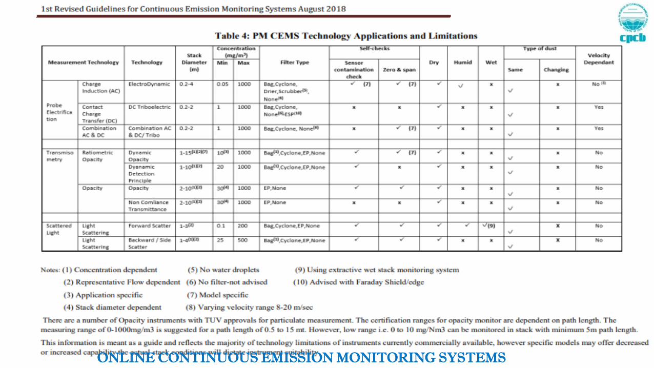
2. Selection of Technology
3. Location of Instruments
4. Range Selection of Instruments
5. Calibration of Instruments
6. Operation and Maintenance of Instruments
7. Verification through Audits
8. Regulatory framework understanding
ONLINE CONTINUOUS EMISSIONMONITORING SYSTEMS

Selection of Technology
Parameter Specific:
Emission:
PM,
SOx
NOx,
CO,
O2,
Flow
ONLINE CONTINUOUS EMISSIONMONITORING SYSTEMS

Clear demarcation of parameters to be monitored by OCEMS in various sectors
ONLINE CONTINUOUS EMISSIONMONITORING SYSTEMS
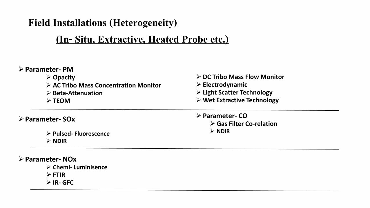
Methods – Gaseous Parameters

Influencing Parameters
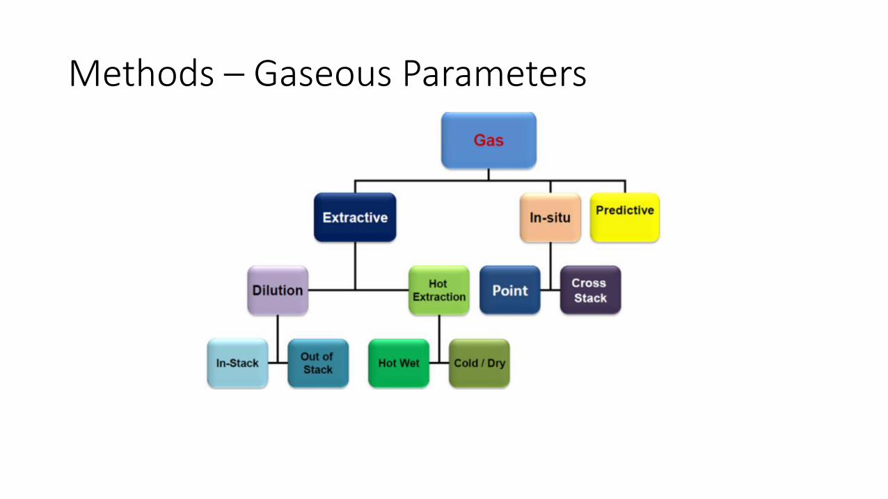
Technology SelectionScenarios :
• A. Concentration Levels dependent –High/Low• Very High – Dilution Technique - Like in Refinery Range- 50 to 1700mg/Nm3
(liquid)
• Dynamic Limits are applied based on gas and liquid ratio- Hence Dynamic limits verification is to be implemented
• FTIR – technique is very useful for low level measurements
• B. Process dependent: - Humidity Levels are high in flue gases• Incinerators CHWI, CBMWI- Measurement techniques which removes
humidity can only be successful.
ONLINE CONTINUOUS EMISSIONMONITORING SYSTEMS

Technology Selection ………………contd.
Scenarios :
• C. Size of Stack –• less than 2 mtrs stack Opacity measurement technique is not suitable in low
ranges
• D. Requirement of Specific Technology like • if industry installs DC Triboelectric based technology, than installation of flow
measurement device is compulsory.
• PM Scintillation technique is Not suitable for >15% Moisture in stack
• TLDS- Tunable Laser Diode system - requires moisture correction
• E. Instrumental Range Selection: atleast 2.5-3.0 Times expected conc.
ONLINE CONTINUOUS EMISSIONMONITORING SYSTEMS

ONLINE CONTINUOUS EMISSIONMONITORING SYSTEMS

Location of Installation of OCEMS Sampling ProbeFor Circular Stacks PM Monitoring location
• At 8D:2D (2D from top)
For Stacks SOx and NOx monitoring
• Either at 8D:2D Location or in the Duct• Without disturbance due to turbulence in flue gas• Verified through stratification study
• Direction of OCEMS Probe• Inlet vertically down
• Location of OCEMS probe vs. Manual monitoring probe• 50 mm above the manual sampling probe
ONLINE CONTINUOUS EMISSIONMONITORING SYSTEMS

Calibration Protocol
• SPAN: As prescribed by Manufacturer of Instrument• Protocol: As suggested by Manufacturers
• If frequency is high means stability of the instrument is low in long duration
• Span Gas Concentration of calibration gas: Near to 3/4th of the measurement range
• Data: Atleast last one year calibration details for verification
• Performance verification check conditions stipulated for:• Zero drift• Span drift• Linearity • Less than 10% of compared reference measurement
ONLINE CONTINUOUS EMISSIONMONITORING SYSTEMS

Operation of Instruments
• Zero on daily basis at 10 am through automatic process
• Span on fortnightly basis through automatic process
• Upon major maintenance each time
• Environmental conditions management
• Continuous flow monitoring ensured
• System Alarm Management
ONLINE CONTINUOUS EMISSIONMONITORING SYSTEMS

Data reporting
• Continuous reporting of all parameters as per method prescribed• Data
• Diagnostic data
• Calibration data
• Compliance Reporting Protocol• Initial installation data reporting
• Linearity check data - on the basis of different load conditions – Once after installation
• Continuous reporting after every three months
• Quarterly reports submission for calibration and maintenance done
ONLINE CONTINUOUS EMISSIONMONITORING SYSTEMS

THANK YOU