Embed Size (px)
Citation preview

Project Specific Water Quality Management PlanA Template for Projects located within the Santa Ana Watershed Region of Riverside County
Project Title: Insert text here
Development No: Insert text here
Design Review/Case No: Insert text here
Original Date Prepared: Insert text here Revision Date(s): Insert text here
Prepared for Compliance with Regional Board Order No. R8-2010-0033Template revised June 30, 2016
- 1 -
Contact Information:
Prepared for: Insert Developer Name, Address, and Phone Number
Prepared by: Insert Name and Title of Preparer, address, and Phone Number
Preliminary Final

A Brief Introduction
This Project-Specific WQMP Template for the Santa Ana Region has been prepared to help guide you in documenting compliance for your project. Because this document has been designed to specifically document compliance, you will need to utilize the WQMP Guidance Document as your “how-to” manual to help guide you through this process. Both the Template and Guidance Document go hand-in-hand, and will help facilitate a well prepared Project-Specific WQMP. Below is a flowchart for the layout of this Template that will provide the steps required to document compliance.
Section AProject and Site
Information
Section BOptimize Site
Utilization
Section CDelineate Drainage Management Areas
(DMAs)
Section GSource Control
BMPs
Section IOperation,
Maintenance, and Funding
Section FHydromodification
Section EAlternative
Compliance
Section DImplement LID
BMPs
Section HConstruction Plan
Checklist
- 2 -

OWNER’S CERTIFICATION
This Project-Specific Water Quality Management Plan (WQMP) has been prepared for <Owner's Name> by <Preparer's Name> for the <Project Name> project.
This WQMP is intended to comply with the requirements of <Insert City or County Name> for <Insert Ordinance No.> which includes the requirement for the preparation and implementation of a Project-Specific WQMP.
The undersigned, while owning the property/project described in the preceding paragraph, shall be responsible for the implementation and funding of this WQMP and will ensure that this WQMP is amended as appropriate to reflect up-to-date conditions on the site. In addition, the property owner accepts responsibility for interim operation and maintenance of Stormwater BMPs until such time as this responsibility is formally transferred to a subsequent owner. This WQMP will be reviewed with the facility operator, facility supervisors, employees, tenants, maintenance and service contractors, or any other party (or parties) having responsibility for implementing portions of this WQMP. At least one copy of this WQMP will be maintained at the project site or project office in perpetuity. The undersigned is authorized to certify and to approve implementation of this WQMP. The undersigned is aware that implementation of this WQMP is enforceable under <Insert City or County Name> Water Quality Ordinance (Municipal Code Section ).
"I, the undersigned, certify under penalty of law that the provisions of this WQMP have been reviewed and accepted and that the WQMP will be transferred to future successors in interest."
Owner’s Signature Date
Owner’s Printed Name Owner’s Title/Position
PREPARER’S CERTIFICATION
“The selection, sizing and design of stormwater treatment and other stormwater quality and quantity control measures in this plan meet the requirements of Regional Water Quality Control Board Order No. R8-2010-0033 and any subsequent amendments thereto.”
Preparer’s Signature Date
Preparer’s Printed Name Preparer’s Title/Position
Preparer’s Licensure:
- 3 -
Table of ContentsSection A: Project and Site Information.......................................................................................................6
A.1 Maps and Site Plans...........................................................................................................................6A.2 Identify Receiving Waters..................................................................................................................7A.3 Additional Permits/Approvals required for the Project:....................................................................7
Section B: Optimize Site Utilization (LID Principles).....................................................................................8
Section C: Delineate Drainage Management Areas (DMAs)........................................................................9
Section D: Implement LID BMPs................................................................................................................11
D.1 Infiltration Applicability...................................................................................................................11D.2 Harvest and Use Assessment...........................................................................................................12D.3 Bioretention and Biotreatment Assessment...................................................................................14D.4 Feasibility Assessment Summaries..................................................................................................15D.5 LID BMP Sizing.................................................................................................................................15
Section E: Alternative Compliance (LID Waiver Program)..........................................................................16
E.1 Identify Pollutants of Concern.........................................................................................................17E.2 Stormwater Credits..........................................................................................................................18E.3 Sizing Criteria...................................................................................................................................18E.4 Treatment Control BMP Selection...................................................................................................19
Section F: Hydromodification....................................................................................................................20
F.1 Hydrologic Conditions of Concern (HCOC) Analysis.........................................................................20F.2 HCOC Mitigation..............................................................................................................................21
Section G: Source Control BMPs................................................................................................................22
Section H: Construction Plan Checklist......................................................................................................23
Section I: Operation, Maintenance and Funding.......................................................................................24
- 4 -

List of TablesTable A.1 Identification of Receiving Waters...............................................................................................7Table A.2 Other Applicable Permits.............................................................................................................7Table C.1 DMA Classifications......................................................................................................................9Table C.2 Type ‘A’, Self-Treating Areas........................................................................................................9Table C.3 Type ‘B’, Self-Retaining Areas......................................................................................................9Table C.4 Type ‘C’, Areas that Drain to Self-Retaining Areas.....................................................................10Table C.5 Type ‘D’, Areas Draining to BMPs...............................................................................................10Table D.1 Infiltration Feasibility.................................................................................................................11Table D.2 LID Prioritization Summary Matrix.............................................................................................15Table D.3 DCV Calculations for LID BMPs..................................................................................................16Table E.1 Potential Pollutants by Land Use Type.......................................................................................18Table E.2 Water Quality Credits.................................................................................................................19Table E.3 Treatment Control BMP Sizing...................................................................................................19Table E.4 Treatment Control BMP Selection..............................................................................................20Table F.1 Hydrologic Conditions of Concern Summary..............................................................................21Table G.1 Permanent and Operational Source Control Measures.............................................................23Table H.1 Construction Plan Cross-reference............................................................................................24
List of AppendicesAppendix 1: Maps and Site Plans...............................................................................................................24
Appendix 2: Construction Plans.................................................................................................................25
Appendix 3: Soils Information...................................................................................................................26
Appendix 4: Historical Site Conditions.......................................................................................................27
Appendix 5: LID Infeasibility......................................................................................................................28
Appendix 6: BMP Design Details................................................................................................................29
Appendix 7: Hydromodification.................................................................................................................30
Appendix 8: Source Control.......................................................................................................................31
Appendix 9: O&M......................................................................................................................................32
Appendix 10: Educational Materials..........................................................................................................33
- 5 -

Section A: Project and Site Information PROJECT INFORMATION
Type of Project: Insert text here (e.g., commercial, residential, etc.)Planning Area: Insert text hereCommunity Name: Insert text hereDevelopment Name: Insert Planning Area / Community Name/ Development Name, if knownPROJECT LOCATION
Latitude & Longitude (DMS): Insert coordinates hereProject Watershed and Sub-Watershed: Insert text hereGross Acres: Insert text hereAPN(s): Insert text here
Map Book and Page No.: Insert text here
PROJECT CHARACTERISTICS
Proposed or Potential Land Use(s) Insert text hereProposed or Potential SIC Code(s) Insert text hereArea of Impervious Project Footprint (SF) Insert text hereTotal Area of proposed Impervious Surfaces within the Project Footprint (SF)/or Replacement
Insert text here
Does the project consist of offsite road improvements? Y NDoes the project propose to construct unpaved roads? Y NIs the project part of a larger common plan of development (phased project)? Y NEXISTING SITE CHARACTERISTICS
Total area of existing Impervious Surfaces within the Project limits Footprint (SF) Insert text here.Is the project located within any MSHCP Criteria Cell? Y NIf so, identify the Cell number: Insert text here.Are there any natural hydrologic features on the project site? Y NIs a Geotechnical Report attached? Y NIf no Geotech. Report, list the NRCS soils type(s) present on the site (A, B, C and/or D) Insert text here.What is the Water Quality Design Storm Depth for the project? Insert text here.
A.1 Maps and Site PlansWhen completing your Project-Specific WQMP, include a map of the local vicinity and existing site. In addition, include all grading, drainage, landscape/plant palette and other pertinent construction plans in Appendix 2. At a minimum, your WQMP Site Plan should include the following:
Drainage Management Areas Proposed Structural BMPs Drainage Path Drainage Infrastructure, Inlets, Overflows
Source Control BMPs Buildings, Roof Lines, Downspouts Impervious Surfaces Standard Labeling BMP Locations (Lat/Long)
- 6 -

Use your discretion on whether or not you may need to create multiple sheets or can appropriately accommodate these features on one or two sheets. Keep in mind that the Co-Permittee plan reviewer must be able to easily analyze your project utilizing this template and its associated site plans and maps.
A.2 Identify Receiving WatersUsing Table A.1 below, list in order of upstream to downstream, the receiving waters that the project site is tributary to. Continue to fill each row with the Receiving Water’s 303(d) listed impairments (if any), designated beneficial uses, and proximity, if any, to a RARE beneficial use. Include a map of the receiving waters in Appendix 1.
Table A.1 Identification of Receiving Waters
Receiving Waters
EPA Approved 303(d) List Impairments
Designated Beneficial Uses
Proximity to RARE Beneficial Use
Insert name of 1st receiving water
List any 303(d) impairments of 1st receiving water, including Approved TMDL pollutant limitations
Insert designated beneficial use of 1st receiving water
Insert distance of project to RARE-designated waters (indicate whether feet, yards, or miles)
insert name of 2nd receiving water
List any 303(d) impairments of 2nd receiving water, including Approved TMDL pollutant limitations
Insert designated beneficial use of 2nd receiving water
Insert distance of project to RARE-designated waters (indicate whether feet, yards, or miles)
Insert name of 3rd receiving water
List any 303(d) impairments of 3rd receiving water, including Approved TMDL pollutant limitations
Insert designated beneficial use of 3rd receiving water
Insert distance of project to RARE-designated waters (indicate whether feet, yards, or miles)
A.3 Additional Permits/Approvals required for the Project:Table A.2 Other Applicable Permits
Agency Permit Required
State Department of Fish and Game, 1602 Streambed Alteration Agreement Y N
State Water Resources Control Board, Clean Water Act (CWA) Section 401 Water Quality Cert. Y N
US Army Corps of Engineers, CWA Section 404 Permit Y N
US Fish and Wildlife, Endangered Species Act Section 7 Biological Opinion Y N
Statewide Construction General Permit Coverage Y N
Statewide Industrial General Permit Coverage Y N
Western Riverside MSHCP Consistency Approval (e.g., JPR, DBESP) Y N
Other (please list in the space below as required)
Y N
If yes is answered to any of the questions above, the Co-Permittee may require proof of approval/coverage from those agencies as applicable including documentation of any associated requirements that may affect this Project-Specific WQMP.
- 7 -

Section B: Optimize Site Utilization (LID Principles)Review of the information collected in Section ‘A’ will aid in identifying the principal constraints on site design and selection of LID BMPs as well as opportunities to reduce imperviousness and incorporate LID Principles into the site and landscape design. For example, constraints might include impermeable soils, high groundwater, groundwater pollution or contaminated soils, steep slopes, geotechnical instability, high-intensity land use, heavy pedestrian or vehicular traffic, utility locations or safety concerns. Opportunities might include existing natural areas, low areas, oddly configured or otherwise unbuildable parcels, easements and landscape amenities including open space and buffers (which can double as locations for bioretention BMPs), and differences in elevation (which can provide hydraulic head). Prepare a brief narrative for each of the site optimization strategies described below. This narrative will help you as you proceed with your LID design and explain your design decisions to others.
The 2010 Santa Ana MS4 Permit further requires that LID Retention BMPs (Infiltration Only or Harvest and Use) be used unless it can be shown that those BMPs are infeasible. Therefore, it is important that your narrative identify and justify if there are any constraints that would prevent the use of those categories of LID BMPs. Similarly, you should also note opportunities that exist which will be utilized during project design. Upon completion of identifying Constraints and Opportunities, include these on your WQMP Site plan in Appendix 1.
Consideration of “highest and best use” of the discharge should also be considered. For example, Lake Elsinore is evaporating faster than runoff from natural precipitation can recharge it. Requiring infiltration of 85% of runoff events for projects tributary to Lake Elsinore would only exacerbate current water quality problems associated with Pollutant concentration due to lake water evaporation. In cases where rainfall events have low potential to recharge Lake Elsinore (i.e. no hydraulic connection between groundwater to Lake Elsinore, or other factors), requiring infiltration of Urban Runoff from projects is counterproductive to the overall watershed goals. Project proponents, in these cases, would be allowed to discharge Urban Runoff, provided they used equally effective filtration-based BMPs.
Site Optimization
The following questions are based upon Section 3.2 of the WQMP Guidance Document. Review of the WQMP Guidance Document will help you determine how best to optimize your site and subsequently identify opportunities and/or constraints, and document compliance.
Did you identify and preserve existing drainage patterns? If so, how? If not, why?
Insert narrative here
Did you identify and protect existing vegetation? If so, how? If not, why?
Insert narrative here
Did you identify and preserve natural infiltration capacity? If so, how? If not, why?
Insert narrative here
Did you identify and minimize impervious area? If so, how? If not, why?
- 8 -

Insert narrative here
Did you identify and disperse runoff to adjacent pervious areas? If so, how? If not, why?
Insert narrative here
- 9 -

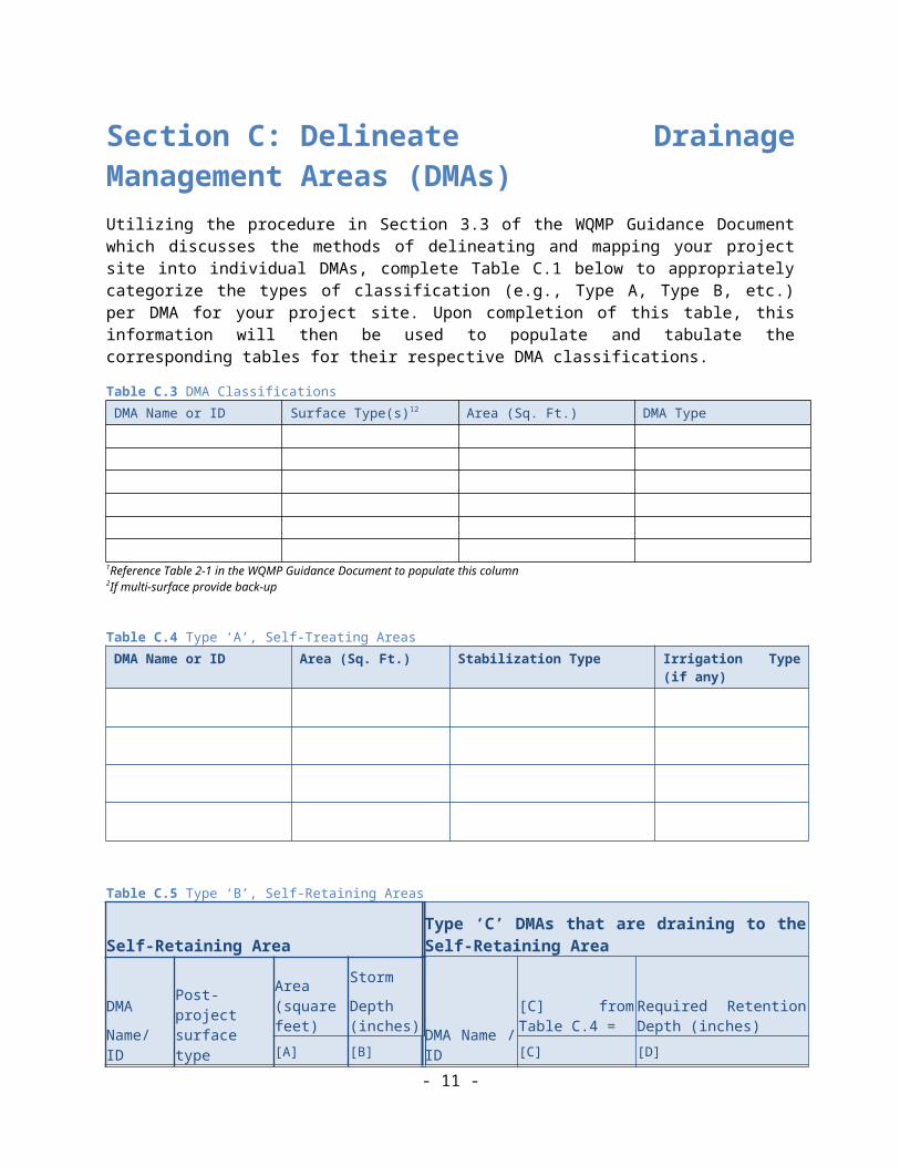
Section C: Delineate Drainage Management Areas (DMAs)Utilizing the procedure in Section 3.3 of the WQMP Guidance Document which discusses the methods of delineating and mapping your project site into individual DMAs, complete Table C.1 below to appropriately categorize the types of classification (e.g., Type A, Type B, etc.) per DMA for your project site. Upon completion of this table, this information will then be used to populate and tabulate the corresponding tables for their respective DMA classifications.
Table C.3 DMA ClassificationsDMA Name or ID Surface Type(s)12 Area (Sq. Ft.) DMA Type
1Reference Table 2-1 in the WQMP Guidance Document to populate this column2If multi-surface provide back-up
Table C.4 Type ‘A’, Self-Treating AreasDMA Name or ID Area (Sq. Ft.) Stabilization Type Irrigation Type (if any)
Table C.5 Type ‘B’, Self-Retaining Areas
Self-Retaining AreaType ‘C’ DMAs that are draining to the Self-Retaining Area
DMA
Name/ IDPost-project surface type
Area (square feet)
Storm
Depth (inches) DMA Name /
ID
[C] from Table C.4 =
Required Retention Depth (inches)
[A] [B] [C] [D]
- 10 -
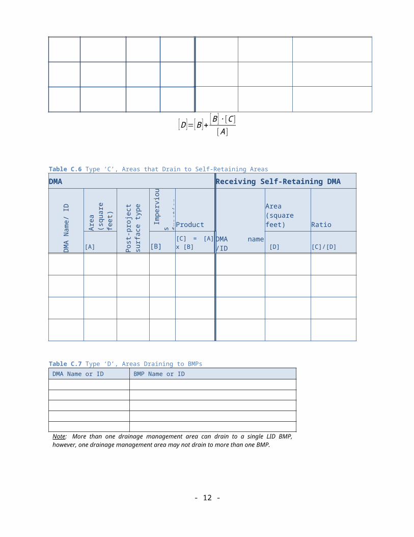
[D ]=[B ]+ [B ] ∙[C ][A ]
Table C.6 Type ‘C’, Areas that Drain to Self-Retaining Areas
DMA Receiving Self-Retaining DMA
DMA
Nam
e/ ID
Area
(s
quar
e fe
et)
Post
-pro
ject
su
rfac
e ty
pe
Im
perv
ious
frac
tion
Product
DMA name /ID
Area (square feet) Ratio
[A] [B] [C] = [A] x [B] [D] [C]/[D]
Table C.7 Type ‘D’, Areas Draining to BMPsDMA Name or ID BMP Name or ID
Note: More than one drainage management area can drain to a single LID BMP, however, one drainage management area may not drain to more than one BMP.
- 11 -

Section D: Implement LID BMPs
D.1 Infiltration Applicability Is there an approved downstream ‘Highest and Best Use’ for stormwater runoff (see discussion in Chapter 2.4.4 of the WQMP Guidance Document for further details)? Y N
If yes has been checked, Infiltration BMPs shall not be used for the site; proceed to section D.3
If no, continue working through this section to implement your LID BMPs. It is recommended that you contact your Co-Permittee to verify whether or not your project discharges to an approved downstream ‘Highest and Best Use’ feature.
Geotechnical Report
A Geotechnical Report or Phase I Environmental Site Assessment may be required by the Copermittee to confirm present and past site characteristics that may affect the use of Infiltration BMPs. In addition, the Co-Permittee, at their discretion, may not require a geotechnical report for small projects as described in Chapter 2 of the WQMP Guidance Document. If a geotechnical report has been prepared, include it in Appendix 3. In addition, if a Phase I Environmental Site Assessment has been prepared, include it in Appendix 4.
Is this project classified as a small project consistent with the requirements of Chapter 2 of the WQMP Guidance Document? Y N
Infiltration Feasibility
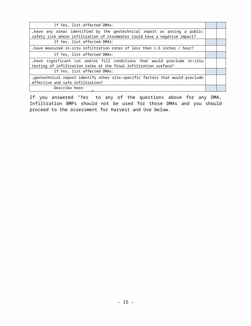
Table D.1 below is meant to provide a simple means of assessing which DMAs on your site support Infiltration BMPs and is discussed in the WQMP Guidance Document in Chapter 2.4.5. Check the appropriate box for each question and then list affected DMAs as applicable. If additional space is needed, add a row below the corresponding answer.
Table D.8 Infiltration FeasibilityDoes the project site… YES NO…have any DMAs with a seasonal high groundwater mark shallower than 10 feet? If Yes, list affected DMAs:…have any DMAs located within 100 feet of a water supply well? If Yes, list affected DMAs:…have any areas identified by the geotechnical report as posing a public safety risk where infiltration of stormwater could have a negative impact? If Yes, list affected DMAs:…have measured in-situ infiltration rates of less than 1.6 inches / hour? If Yes, list affected DMAs:…have significant cut and/or fill conditions that would preclude in-situ testing of infiltration rates at the final infiltration surface? If Yes, list affected DMAs:…geotechnical report identify other site-specific factors that would preclude effective and safe infiltration? Describe here:
If you answered “Yes” to any of the questions above for any DMA, Infiltration BMPs should not be used for those DMAs and you should proceed to the assessment for Harvest and Use below.
- 12 -
D.2 Harvest and Use AssessmentPlease check what applies:
☐ Reclaimed water will be used for the non-potable water demands for the project.
☐Downstream water rights may be impacted by Harvest and Use as approved by the Regional Board (verify with the Copermittee).
☐The Design Capture Volume will be addressed using Infiltration Only BMPs. In such a case, Harvest and Use BMPs are still encouraged, but it would not be required if the Design Capture Volume will be infiltrated or evapotranspired.
If any of the above boxes have been checked, Harvest and Use BMPs need not be assessed for the site. If none of the above criteria applies, follow the steps below to assess the feasibility of irrigation use, toilet use and other non-potable uses (e.g., industrial use).
Irrigation Use Feasibility
Complete the following steps to determine the feasibility of harvesting stormwater runoff for Irrigation Use BMPs on your site:
Step 1: Identify the total area of irrigated landscape on the site, and the type of landscaping used.
Total Area of Irrigated Landscape: Insert Area (Acres)
Type of Landscaping (Conservation Design or Active Turf): List Landscaping Type
Step 2: Identify the planned total of all impervious areas on the proposed project from which runoff might be feasibly captured and stored for irrigation use. Depending on the configuration of buildings and other impervious areas on the site, you may consider the site as a whole, or parts of the site, to evaluate reasonable scenarios for capturing and storing runoff and directing the stored runoff to the potential use(s) identified in Step 1 above.
Total Area of Impervious Surfaces: Insert Area (Acres)
Step 3: Cross reference the Design Storm depth for the project site (see Exhibit A of the WQMP Guidance Document) with the left column of Table 2-3 in Chapter 2 to determine the minimum area of Effective Irrigated Area per Tributary Impervious Area (EIATIA).
Enter your EIATIA factor: EIATIA Factor
Step 4: Multiply the unit value obtained from Step 3 by the total of impervious areas from Step 2 to develop the minimum irrigated area that would be required.
Minimum required irrigated area: Insert Area (Acres)
Step 5: Determine if harvesting stormwater runoff for irrigation use is feasible for the project by comparing the total area of irrigated landscape (Step 1) to the minimum required irrigated area (Step 4).
Minimum required irrigated area (Step 4) Available Irrigated Landscape (Step 1)
Insert Area (Acres) Insert Area (Acres)
- 13 -
Toilet Use Feasibility
Complete the following steps to determine the feasibility of harvesting stormwater runoff for toilet flushing uses on your site:
Step 1: Identify the projected total number of daily toilet users during the wet season, and account for any periodic shut downs or other lapses in occupancy:
Projected Number of Daily Toilet Users: Number of daily Toilet Users
Project Type: Enter 'Residential', 'Commercial', 'Industrial' or 'Schools'
Step 2: Identify the planned total of all impervious areas on the proposed project from which runoff might be feasibly captured and stored for toilet use. Depending on the configuration of buildings and other impervious areas on the site, you may consider the site as a whole, or parts of the site, to evaluate reasonable scenarios for capturing and storing runoff and directing the stored runoff to the potential use(s) identified in Step 1 above.
Total Area of Impervious Surfaces: Insert Area (Acres)
Step 3: Enter the Design Storm depth for the project site (see Exhibit A) into the left column of Table 2-2 in Chapter 2 to determine the minimum number or toilet users per tributary impervious acre (TUTIA).
Enter your TUTIA factor: TUTIA Factor
Step 4: Multiply the unit value obtained from Step 3 by the total of impervious areas from Step 2 to develop the minimum number of toilet users that would be required.
Minimum number of toilet users: Required number of toilet users
Step 5: Determine if harvesting stormwater runoff for toilet flushing use is feasible for the project by comparing the Number of Daily Toilet Users (Step 1) to the minimum required number of toilet users (Step 4).
Minimum required Toilet Users (Step 4) Projected number of toilet users (Step 1)
Insert Area (Acres) Insert Area (Acres)
Other Non-Potable Use Feasibility
Are there other non-potable uses for stormwater runoff on the site (e.g. industrial use)? See Chapter 2 of the Guidance for further information. If yes, describe below. If no, write N/A.
Insert narrative description here.
Step 1: Identify the projected average daily non-potable demand, in gallons per day, during the wet season and accounting for any periodic shut downs or other lapses in occupancy or operation.
Average Daily Demand: Projected Average Daily Use (gpd)
Step 2: Identify the planned total of all impervious areas on the proposed project from which runoff might be feasibly captured and stored for the identified non-potable use. Depending on the configuration of buildings and other impervious areas on the site, you may consider the site as a whole, or parts of the site, to evaluate reasonable scenarios for capturing and storing runoff and directing the stored runoff to the potential use(s) identified in Step 1 above.
Total Area of Impervious Surfaces: Insert Area (Acres)- 14 -

Step 3: Enter the Design Storm depth for the project site (see Exhibit A) into the left column of Table 2-4 in Chapter 2 to determine the minimum demand for non-potable uses per tributary impervious acre.
Enter the factor from Table 2-4: Enter Value
Step 4: Multiply the unit value obtained from Step 3 by the total of impervious areas from Step 2 to develop the minimum number of gallons per day of non-potable use that would be required.
Minimum required use: Minimum use required (gpd)
Step 5: Determine if harvesting stormwater runoff for other non-potable use is feasible for the project by comparing the projected average daily use (Step 1) to the minimum required non-potable use (Step 4).
Minimum required non-potable use (Step 4) Projected average daily use (Step 1)
Minimum use required (gpd) Projected Average Daily Use (gpd)
If Irrigation, Toilet and Other Use feasibility anticipated demands are less than the applicable minimum values, Harvest and Use BMPs are not required and you should proceed to utilize LID Bioretention and Biotreatment per Section 3.4.2 of the WQMP Guidance Document.
D.3 Bioretention and Biotreatment AssessmentOther LID Bioretention and Biotreatment BMPs as described in Chapter 2.4.7 of the WQMP Guidance Document are feasible on nearly all development sites with sufficient advance planning.
Select one of the following:
☐ LID Bioretention/Biotreatment BMPs will be used for some or all DMAs of the project as noted below in Section D.4 (note the requirements of Section 3.4.2 in the WQMP Guidance Document).
☐ A site-specific analysis demonstrating the technical infeasibility of all LID BMPs has been performed and is included in Appendix 5. If you plan to submit an analysis demonstrating the technical infeasibility of LID BMPs, request a pre-submittal meeting with the Copermittee to discuss this option. Proceed to Section E to document your alternative compliance measures.
- 15 -

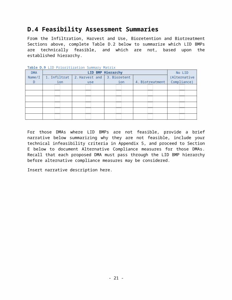
D.4 Feasibility Assessment SummariesFrom the Infiltration, Harvest and Use, Bioretention and Biotreatment Sections above, complete Table D.2 below to summarize which LID BMPs are technically feasible, and which are not, based upon the established hierarchy.
Table D.9 LID Prioritization Summary Matrix
DMA Name/ID
LID BMP Hierarchy No LID (Alternative Compliance)1. Infiltration 2. Harvest and use 3. Bioretention 4. Biotreatment
For those DMAs where LID BMPs are not feasible, provide a brief narrative below summarizing why they are not feasible, include your technical infeasibility criteria in Appendix 5, and proceed to Section E below to document Alternative Compliance measures for those DMAs. Recall that each proposed DMA must pass through the LID BMP hierarchy before alternative compliance measures may be considered.
Insert narrative description here.
- 16 -
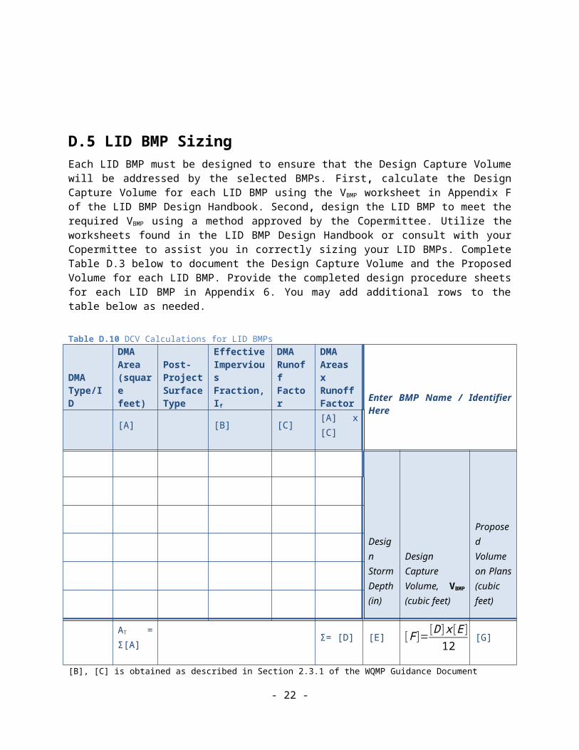
D.5 LID BMP Sizing Each LID BMP must be designed to ensure that the Design Capture Volume will be addressed by the selected BMPs. First, calculate the Design Capture Volume for each LID BMP using the VBMP worksheet in Appendix F of the LID BMP Design Handbook. Second, design the LID BMP to meet the required VBMP
using a method approved by the Copermittee. Utilize the worksheets found in the LID BMP Design Handbook or consult with your Copermittee to assist you in correctly sizing your LID BMPs. Complete Table D.3 below to document the Design Capture Volume and the Proposed Volume for each LID BMP. Provide the completed design procedure sheets for each LID BMP in Appendix 6. You may add additional rows to the table below as needed.
Table D.10 DCV Calculations for LID BMPs
DMA Type/ID
DMA Area (square feet)
Post-Project Surface Type
Effective Impervious Fraction, If
DMA Runoff Factor
DMA Areas x Runoff Factor
Enter BMP Name / Identifier Here
[A] [B] [C] [A] x [C]
Design Storm Depth (in)
Design Capture Volume, VBMP
(cubic feet)
Proposed Volume on Plans (cubic feet)
AT = Σ[A] Σ= [D] [E] [F ]=[D ]x [E]
12[G]
[B], [C] is obtained as described in Section 2.3.1 of the WQMP Guidance Document[E] is obtained from Exhibit A in the WQMP Guidance Document[G] is obtained from a design procedure sheet, such as in LID BMP Design Handbook and placed in Appendix 6
- 17 -

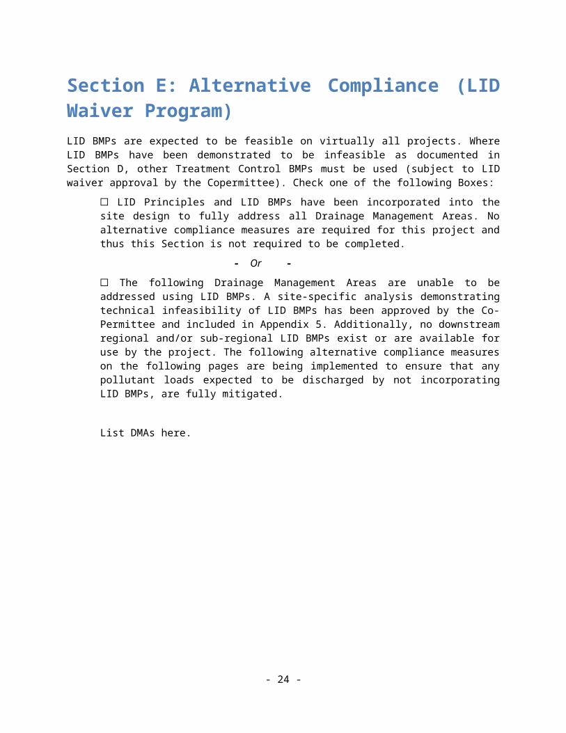
Section E: Alternative Compliance (LID Waiver Program)LID BMPs are expected to be feasible on virtually all projects. Where LID BMPs have been demonstrated to be infeasible as documented in Section D, other Treatment Control BMPs must be used (subject to LID waiver approval by the Copermittee). Check one of the following Boxes:
☐ LID Principles and LID BMPs have been incorporated into the site design to fully address all Drainage Management Areas. No alternative compliance measures are required for this project and thus this Section is not required to be completed.
- Or -
☐ The following Drainage Management Areas are unable to be addressed using LID BMPs. A site-specific analysis demonstrating technical infeasibility of LID BMPs has been approved by the Co-Permittee and included in Appendix 5. Additionally, no downstream regional and/or sub-regional LID BMPs exist or are available for use by the project. The following alternative compliance measures on the following pages are being implemented to ensure that any pollutant loads expected to be discharged by not incorporating LID BMPs, are fully mitigated.
List DMAs here.
- 18 -

E.1 Identify Pollutants of ConcernUtilizing Table A.1 from Section A above which noted your project’s receiving waters and their associated EPA approved 303(d) listed impairments, cross reference this information with that of your selected Priority Development Project Category in Table E.1 below. If the identified General Pollutant Categories are the same as those listed for your receiving waters, then these will be your Pollutants of Concern and the appropriate box or boxes will be checked on the last row. The purpose of this is to document compliance and to help you appropriately plan for mitigating your Pollutants of Concern in lieu of implementing LID BMPs.
Table E.11 Potential Pollutants by Land Use Type
Priority Development Project Categories and/or Project Features (check those that apply)
General Pollutant Categories
Bacterial Indicators Metals Nutrients Pesticides
Toxic Organic Compounds
Sediments Trash & Debris
Oil & Grease
Detached Residential Development P N P P N P P P
Attached Residential Development P N P P N P P P(2)
Commercial/Industrial Development P(3) P P(1) P(1) P(5) P(1) P P
Automotive Repair Shops N P N N P(4, 5) N P P
Restaurants(>5,000 ft2)
P N N N N N P P
Hillside Development(>5,000 ft2)
P N P P N P P P
Parking Lots(>5,000 ft2)
P(6) P P(1) P(1) P(4) P(1) P P
Retail Gasoline Outlets N P N N P N P P
Project Priority Pollutant(s) of ConcernP = PotentialN = Not Potential(1) A potential Pollutant if non-native landscaping exists or is proposed onsite; otherwise not expected(2) A potential Pollutant if the project includes uncovered parking areas; otherwise not expected(3) A potential Pollutant is land use involving animal waste(4) Specifically petroleum hydrocarbons(5) Specifically solvents(6) Bacterial indicators are routinely detected in pavement runoff
- 19 -

E.2 Stormwater CreditsProjects that cannot implement LID BMPs but nevertheless implement smart growth principles are potentially eligible for Stormwater Credits. Utilize Table 3-8 within the WQMP Guidance Document to identify your Project Category and its associated Water Quality Credit. If not applicable, write N/A.
Table E.12 Water Quality CreditsQualifying Project Categories Credit Percentage2
Total Credit Percentage1
1Cannot Exceed 50%2Obtain corresponding data from Table 3-8 in the WQMP Guidance Document
E.3 Sizing CriteriaAfter you appropriately considered Stormwater Credits for your project, utilize Table E.3 below to appropriately size them to the DCV, or Design Flow Rate, as applicable. Please reference Chapter 3.5.2 of the WQMP Guidance Document for further information.
Table E.13 Treatment Control BMP Sizing
DMA Type/ID
DMA Area (square feet)
Post-Project Surface Type
Effective Impervious Fraction, If
DMA Runoff Factor
DMA Area x Runoff Factor
Enter BMP Name / Identifier Here
[A] [B] [C] [A] x [C]
Design Storm Depth (in)
Minimum Design Capture Volume or Design Flow Rate (cubic feet or cfs)
Total Storm Water Credit % Reduction
Proposed Volume or Flow on Plans (cubic feet or cfs)
AT = Σ[A]
Σ= [D] [E] [F ]=[D ]x [E]
[G ][F] X (1-[H]) [I]
[B], [C] is obtained as described in Section 2.3.1 from the WQMP Guidance Document[E] is for Flow-Based Treatment Control BMPs [E] = .2, for Volume-Based Control Treatment BMPs, [E] obtained from Exhibit A in the WQMP Guidance Document[G] is for Flow-Based Treatment Control BMPs [G] = 43,560, for Volume-Based Control Treatment BMPs, [G] = 12[H] is from the Total Credit Percentage as Calculated from Table E.2 above
- 20 -

[I] as obtained from a design procedure sheet from the BMP manufacturer and should be included in Appendix 6
- 21 -

E.4 Treatment Control BMP SelectionTreatment Control BMPs typically provide proprietary treatment mechanisms to treat potential pollutants in runoff, but do not sustain significant biological processes. Treatment Control BMPs must have a removal efficiency of a medium or high effectiveness as quantified below:
High: equal to or greater than 80% removal efficiency Medium: between 40% and 80% removal efficiency
Such removal efficiency documentation (e.g., studies, reports, etc.) as further discussed in Chapter 3.5.2 of the WQMP Guidance Document, must be included in Appendix 6. In addition, ensure that proposed Treatment Control BMPs are properly identified on the WQMP Site Plan in Appendix 1.
Table E.14 Treatment Control BMP Selection Selected Treatment Control BMP Name or ID1
Priority Pollutant(s) of Concern to Mitigate2
Removal Efficiency Percentage3
1 Treatment Control BMPs must not be constructed within Receiving Waters. In addition, a proposed Treatment Control BMP may be listed more than once if they possess more than one qualifying pollutant removal efficiency.2 Cross Reference Table E.1 above to populate this column.3 As documented in a Co-Permittee Approved Study and provided in Appendix 6.
- 22 -
Section F: HydromodificationF.1 Hydrologic Conditions of Concern (HCOC) AnalysisOnce you have determined that the LID design is adequate to address water quality requirements, you will need to assess if the proposed LID Design may still create a HCOC. Review Chapters 2 and 3 (including Figure 3-7) of the WQMP Guidance Document to determine if your project must mitigate for Hydromodification impacts. If your project meets one of the following criteria which will be indicated by the check boxes below, you do not need to address Hydromodification at this time. However, if the project does not qualify for Exemptions 1, 2 or 3, then additional measures must be added to the design to comply with HCOC criteria. This is discussed in further detail below in Section F.2.
HCOC EXEMPTION 1: The Priority Development Project disturbs less than one acre. The Copermittee has the discretion to require a Project-Specific WQMP to address HCOCs on projects less than one acre on a case by case basis. The disturbed area calculation should include all disturbances associated with larger common plans of development.
Does the project qualify for this HCOC Exemption? Y N
If Yes, HCOC criteria do not apply.
HCOC EXEMPTION 2: The volume and time of concentration1 of storm water runoff for the post-development condition is not significantly different from the pre-development condition for a 2-year return frequency storm (a difference of 5% or less is considered insignificant) using one of the following methods to calculate:
Riverside County Hydrology Manual
Technical Release 55 (TR-55): Urban Hydrology for Small Watersheds (NRCS 1986), or derivatives thereof, such as the Santa Barbara Urban Hydrograph Method
Other methods acceptable to the Co-Permittee
Does the project qualify for this HCOC Exemption? Y N
If Yes, report results in Table F.1 below and provide your substantiated hydrologic analysis in Appendix 7.
Table F.15 Hydrologic Conditions of Concern Summary2 year – 24 hour
Pre-condition Post-condition % Difference
Time of Concentration
INSERT VALUE INSERT VALUE INSERT VALUE
Volume (Cubic Feet) INSERT VALUE INSERT VALUE INSERT VALUE
1 Time of concentration is defined as the time after the beginning of the rainfall when all portions of the drainage basin are contributing to flow at the outlet.
- 23 -
HCOC EXEMPTION 3: All downstream conveyance channels to an adequate sump (for example, Prado Dam, Lake Elsinore, Canyon Lake, Santa Ana River, or other lake, reservoir or naturally erosion resistant feature) that will receive runoff from the project are engineered and regularly maintained to ensure design flow capacity; no sensitive stream habitat areas will be adversely affected; or are not identified on the Co-Permittees Hydromodification Susceptibility Maps.
Does the project qualify for this HCOC Exemption? Y N
If Yes, HCOC criteria do not apply and note below which adequate sump applies to this HCOC qualifier:
INSERT TEXT HERE
F.2 HCOC MitigationIf none of the above HCOC Exemption Criteria are applicable, HCOC criteria is considered mitigated if they meet one of the following conditions:
a. Additional LID BMPS are implemented onsite or offsite to mitigate potential erosion or habitat impacts as a result of HCOCs. This can be conducted by an evaluation of site-specific conditions utilizing accepted professional methodologies published by entities such as the California Stormwater Quality Association (CASQA), the Southern California Coastal Water Research Project (SCCRWP), or other Co-Permittee approved methodologies for site-specific HCOC analysis.
b. The project is developed consistent with an approved Watershed Action Plan that addresses HCOC in Receiving Waters.
c. Mimicking the pre-development hydrograph with the post-development hydrograph, for a 2-year return frequency storm. Generally, the hydrologic conditions of concern are not significant, if the post-development hydrograph is no more than 10% greater than pre-development hydrograph. In cases where excess volume cannot be infiltrated or captured and reused, discharge from the site must be limited to a flow rate no greater than 110% of the pre-development 2-year peak flow.
Be sure to include all pertinent documentation used in your analysis of the items a, b or c in Appendix 7.
- 24 -

Section G: Source Control BMPsSource control BMPs include permanent, structural features that may be required in your project plans — such as roofs over and berms around trash and recycling areas — and Operational BMPs, such as regular sweeping and “housekeeping”, that must be implemented by the site’s occupant or user. The MEP standard typically requires both types of BMPs. In general, Operational BMPs cannot be substituted for a feasible and effective permanent BMP. Using the Pollutant Sources/Source Control Checklist in Appendix 8, review the following procedure to specify Source Control BMPs for your site:
1. Identify Pollutant Sources: Review Column 1 in the Pollutant Sources/Source Control Checklist. Check off the potential sources of Pollutants that apply to your site.
2. Note Locations on Project-Specific WQMP Exhibit: Note the corresponding requirements listed in Column 2 of the Pollutant Sources/Source Control Checklist. Show the location of each Pollutant source and each permanent Source Control BMP in your Project-Specific WQMP Exhibit located in Appendix 1.
3. Prepare a Table and Narrative: Check off the corresponding requirements listed in Column 3 in the Pollutant Sources/Source Control Checklist. In the left column of Table G.1 below, list each potential source of runoff Pollutants on your site (from those that you checked in the Pollutant Sources/Source Control Checklist). In the middle column, list the corresponding permanent, Structural Source Control BMPs (from Columns 2 and 3 of the Pollutant Sources/Source Control Checklist) used to prevent Pollutants from entering runoff. Add additional narrative in this column that explains any special features, materials or methods of construction that will be used to implement these permanent, Structural Source Control BMPs.
4. Identify Operational Source Control BMPs: To complete your table, refer once again to the Pollutant Sources/Source Control Checklist. List in the right column of your table the Operational BMPs that should be implemented as long as the anticipated activities continue at the site. Copermittee stormwater ordinances require that applicable Source Control BMPs be implemented; the same BMPs may also be required as a condition of a use permit or other revocable Discretionary Approval for use of the site.
Table G.16 Permanent and Operational Source Control Measures
Potential Sources of Runoff pollutants
Permanent Structural Source Control BMPs
Operational Source Control BMPs
- 25 -
- 26 -

Section H: Construction Plan ChecklistPopulate Table H.1 below to assist the plan checker in an expeditious review of your project. The first two columns will contain information that was prepared in previous steps, while the last column will be populated with the corresponding plan sheets. This table is to be completed with the submittal of your final Project-Specific WQMP.
Table H.17 Construction Plan Cross-reference
BMP No. or ID
BMP Identifier and Description
Corresponding Plan Sheet(s) BMP Location (Lat/Long)
Note that the updated table — or Construction Plan WQMP Checklist — is only a reference tool to facilitate an easy comparison of the construction plans to your Project-Specific WQMP. Co-Permittee staff can advise you regarding the process required to propose changes to the approved Project-Specific WQMP.
- 27 -

Section I: Operation, Maintenance and FundingThe Copermittee will periodically verify that Stormwater BMPs on your site are maintained and continue to operate as designed. To make this possible, your Copermittee will require that you include in Appendix 9 of this Project-Specific WQMP:
1. A means to finance and implement facility maintenance in perpetuity, including replacement cost.
2. Acceptance of responsibility for maintenance from the time the BMPs are constructed until responsibility for operation and maintenance is legally transferred. A warranty covering a period following construction may also be required.
3. An outline of general maintenance requirements for the Stormwater BMPs you have selected.
4. Figures delineating and designating pervious and impervious areas, location, and type of Stormwater BMP, and tables of pervious and impervious areas served by each facility. Geo-locating the BMPs using a coordinate system of latitude and longitude is recommended to help facilitate a future statewide database system.
5. A separate list and location of self-retaining areas or areas addressed by LID Principles that do not require specialized O&M or inspections but will require typical landscape maintenance as noted in Chapter 5, pages 85-86, in the WQMP Guidance. Include a brief description of typical landscape maintenance for these areas.
Your local Co-Permittee will also require that you prepare and submit a detailed Stormwater BMP Operation and Maintenance Plan that sets forth a maintenance schedule for each of the Stormwater BMPs built on your site. An agreement assigning responsibility for maintenance and providing for inspections and certification may also be required.
Details of these requirements and instructions for preparing a Stormwater BMP Operation and Maintenance Plan are in Chapter 5 of the WQMP Guidance Document.
Maintenance Mechanism: Insert text here.
Will the proposed BMPs be maintained by a Home Owners’ Association (HOA) or Property Owners Association (POA)?
Y N
Include your Operation and Maintenance Plan and Maintenance Mechanism in Appendix 9. Additionally, include all pertinent forms of educational materials for those personnel that will be maintaining the proposed BMPs within this Project-Specific WQMP in Appendix 10.
- 28 -

Appendix 1: Maps and Site PlansLocation Map, WQMP Site Plan and Receiving Waters Map
- 29 -

Appendix 2: Construction PlansGrading and Drainage Plans
- 30 -

Appendix 3: Soils InformationGeotechnical Study and Other Infiltration Testing Data
- 31 -

Appendix 4: Historical Site ConditionsPhase I Environmental Site Assessment or Other Information on Past Site Use
- 32 -

Appendix 5: LID InfeasibilityLID Technical Infeasibility Analysis
- 33 -

Appendix 6: BMP Design DetailsBMP Sizing, Design Details and other Supporting Documentation
- 34 -

Appendix 7: HydromodificationSupporting Detail Relating to Hydrologic Conditions of Concern
- 35 -

Appendix 8: Source ControlPollutant Sources/Source Control Checklist
- 36 -

Appendix 9: O&MOperation and Maintenance Plan and Documentation of Finance, Maintenance and Recording Mechanisms
- 37 -

Appendix 10: Educational MaterialsBMP Fact Sheets, Maintenance Guidelines and Other End-User BMP Information
6