Embed Size (px)
Citation preview

1
Abstract—This paper describes an observer design method that
estimates the exhaust manifold pressure in a diesel engine with limited sensor information. In the modern model-based control of air flows, information on the exhaust pressure is often necessary for control stability. However, it is not easy to measure the exhaust pressure with sensors due to the unfavorable environment for measurement and the high cost of sensors. Therefore, a robust observer, which is applicable to engines equipped with a dual-loop exhaust gas recirculation (EGR) system and a variable geometry turbine (VGT), is designed to estimate the exhaust pressure. The observer takes the form of a Luenberger-sliding mode observer in order to guarantee its asymptotic stability upon consideration of the model uncertainties. For research on state estimation and control of dual-loop EGR engines, information on the pressure states in the low pressure (LP) EGR loop must be provided. Hence, this paper also proposes an intuitive regression modeling method for the pressure states of the compressor inlet and turbine outlet with physical insights into the engine operation. Applying the regression models to the observer algorithm, the estimation performance of the exhaust pressure observer is verified experimentally in both steady state and transient conditions with a 6 L heavy-duty diesel engine.
Index Terms—Diesel engine control, Dual-loop EGR, Exhaust pressure estimation, Lyapunov stability, Sliding mode observer
I. INTRODUCTION S environmental regulations for diesel engines have become increasingly strict, the development of
environmentally friendly engines has become a significant issue. The hazardous substances emitted from a diesel engine consist of hydrocarbon (HC), nitrogen oxide (NOx), and particulate matter (PM). In order to manage these substances, various configurations have been applied to diesel engines. Nowadays, most diesel engines are equipped with variable geometry turbine (VGT) and exhaust gas recirculation (EGR) systems. With the combination of the EGR and VGT systems, the reduction of emissions without sacrificing vehicle performance is achievable in real applications. Recently, dual-loop EGR systems, which use high pressure (HP) EGR and low pressure (LP) EGR systems simultaneously, have been implemented in the air flow path of diesel engines in order to effectively use the EGR functions. With the direct recirculation of hot exhaust gases, the HP EGR increases the temperature and EGR rate in the intake manifold of diesel engines, and the LP EGR recirculates clean and relatively cool EGR gases that come through the after-treatment systems and an EGR cooler [1-3]. In terms of control, the air flow system is a highly
coupled nonlinear system, and the concept of model-based control for engines was developed in order to treat these coupling properties of the system effectively. Many studies have been conducted on the model-based control of single-loop EGR systems [4-13] and a few studies have focused on dual-loop EGR systems recently [1-3, 14, 15].
Information on the exhaust pressure is essential in the engine air flow control because it contains important data on the engine operation status. For example, exhaust manifold pressure is primarily concerned with the flow rates of turbine and HP EGR, for which any variation has a significant influence on the entire system, and is regarded as one of states to be controlled in engines with VGT and EGR [7, 13]. Even though it is not directly related to specific engine performances, its value has crucial effects on other states. In addition, with respect to the design of the controller, the exhaust pressure should be selected as a control output in order to guarantee internal stability of the control system [7, 10, 15]. However, it is not easy to measure the exhaust pressure with a production sensor. The environment is not appropriate for measurements due to the large oscillations of the flow, high pressure, and high temperature; moreover, the sensor becomes cost prohibitive in production engines [16, 17].
Since the 2000s, various studies have been conducted on model-based estimation methods for the exhaust pressure in order to overcome the limitations of the conventional map-based estimation methods. Andersson and Eriksson proposed an estimation method for the exhaust pressure based on the first law of thermodynamics and a model of the mass of the residual exhaust gases in the cylinder [18, 19]. A nonlinear model-based observer was designed in [16]. In [20], the compressible flow equation was used to implement a mean-value model for the exhaust manifold pressure, and Buckland et al. considered a reduced order observer with a simple lead compensation in order to enhance the transient estimation performance [21]. Chiara and Canova proposed an estimation method for the exhaust manifold pressure in a diesel engine with a two-stage turbocharger based on the inversion of a turbocharger model [22]. Recently, Siokos et al. developed pressure models for exhaust manifold and turbine outlet in a gasoline engine with LP EGR system [23].
However, these works have not considered the simultaneous operations of an EGR and VGT system in the engine, which makes it much easier to calibrate the systems. Because the exhaust manifold pressure is directly related to the operations of the EGR and VGT, estimation methods that can consider
Exhaust Pressure Estimation for Diesel Engines Equipped with Dual-loop EGR and VGT
Sooyoung Kim, Hyomin Jin, and Seibum B. Choi, Member, IEEE
A
2
these EGR and VGT operations simultaneously in real time are needed. Recently, some studies have been undertaken on the exhaust pressure estimation for engines with HP EGR and VGT [17, 24, 25]. In [17], a model-based method using a coordinate transformation to generate a turbine map was developed to estimate the exhaust pressure. Lee et al. designed a nonlinear sliding mode observer, and Jin et al. proposed an estimation method based on compressor dynamics [24, 25]. The limitation of these studies is that, even though dual-loop EGR systems are commonly installed in diesel engines, practical studies on the estimation of the exhaust manifold pressure for dual-loop EGR engines remain absent. In [26], an exhaust pressure estimator using extrapolated VGT data maps with the effect of the turbine speed was proposed for a dual-loop EGR and VGT system; however, the authors used impractical sensor information such as the universal exhaust gas oxygen (UEGO) sensor signal. In this study, the estimation algorithm of the observer for the exhaust manifold pressure that is applicable to a diesel engine equipped with a dual-loop EGR and VGT system is proposed using only limited sensor information.
In order to estimate the exhaust pressure of a dual-loop EGR system, information on the states of the LP EGR loop is essential. Because the mass flow rate of the LP EGR cannot be measured, the values for the pressure and temperature in the compressor inlet and turbine outlet, which represent the LP EGR loop, should be known in order to calculate the flow rate. However, the pressure states in the LP EGR loop, e.g. the turbine outlet pressure and compressor inlet pressure, are not measurable in production engines, which is a critical obstacle in research on dual-loop EGR engine control. Thus, this paper also develops a regression modeling method of the pressure states in the compressor inlet and turbine outlet that considers the physical characteristics of an engine with a dual-loop EGR. The pressure values predicted by the regression models are used in the final observer algorithm for the exhaust manifold pressure.
The proposed observer is a robust sliding mode observer with a simple second-order form considering the simplicity of the implementation and model uncertainties. Using production sensors such as the mass air flow (MAF) and manifold absolute pressure (MAP) sensors and a minimum number of map-based sub-models, the observer can estimate the exhaust pressure accurately in various conditions, which also include transient operations.
The remainder of this paper is organized as follows. In Section II, a system overview and the principal equations of the model for the air flow system in a dual-loop EGR system are described. Section III presents the design process of the sliding mode observer for the exhaust manifold pressure. In Section IV, concerns about the dual-loop EGR system for the observer design are investigated, and a new modeling method for the pressure states in the LP EGR loop is introduced. Finally, in Section V, the estimation performance of the observer with the pressure models of the LP EGR loop is experimentally evaluated in both steady state and transient conditions using a 6 L heavy-duty diesel engine with dual-loop EGR and VGT.
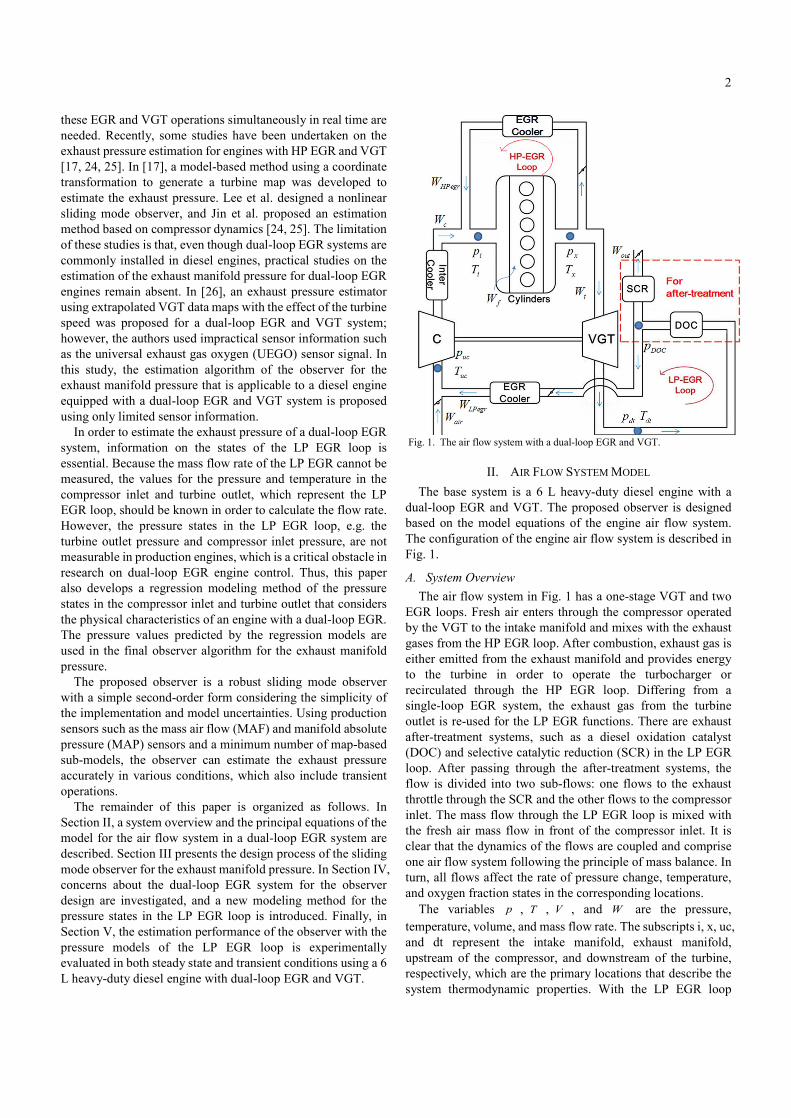
Fig. 1. The air flow system with a dual-loop EGR and VGT.
II. AIR FLOW SYSTEM MODEL The base system is a 6 L heavy-duty diesel engine with a
dual-loop EGR and VGT. The proposed observer is designed based on the model equations of the engine air flow system. The configuration of the engine air flow system is described in Fig. 1.
A. System Overview The air flow system in Fig. 1 has a one-stage VGT and two
EGR loops. Fresh air enters through the compressor operated by the VGT to the intake manifold and mixes with the exhaust gases from the HP EGR loop. After combustion, exhaust gas is either emitted from the exhaust manifold and provides energy to the turbine in order to operate the turbocharger or recirculated through the HP EGR loop. Differing from a single-loop EGR system, the exhaust gas from the turbine outlet is re-used for the LP EGR functions. There are exhaust after-treatment systems, such as a diesel oxidation catalyst (DOC) and selective catalytic reduction (SCR) in the LP EGR loop. After passing through the after-treatment systems, the flow is divided into two sub-flows: one flows to the exhaust throttle through the SCR and the other flows to the compressor inlet. The mass flow through the LP EGR loop is mixed with the fresh air mass flow in front of the compressor inlet. It is clear that the dynamics of the flows are coupled and comprise one air flow system following the principle of mass balance. In turn, all flows affect the rate of pressure change, temperature, and oxygen fraction states in the corresponding locations.
The variables p , T , V , and W are the pressure, temperature, volume, and mass flow rate. The subscripts i, x, uc, and dt represent the intake manifold, exhaust manifold, upstream of the compressor, and downstream of the turbine, respectively, which are the primary locations that describe the system thermodynamic properties. With the LP EGR loop

3
added, the dynamics at the compressor upstream and the turbine downstream are important in terms of the intake and exhaust manifolds. That is, the dual-loop EGR system is significantly more complicated than the single-loop system and thus is more difficult to analyze. The model equations that have been validated in previous papers (e.g. [7, 8, 12]) are introduced in this section. The principal equations are described in (1)-(8).
B. Pressure Dynamics Based on the first law of thermodynamics, the pressure
dynamics of the diesel engine air system with the dual-loop EGR are described as follows:
( ) ,i c c HPegr HPegr i iei
Rp T W T W TWVg
= + -& (1)
( ) ,x e ex x HPegr x tx
Rp T W T W T WVg
= - -& (2)
( ) ,uc a air dt LPegr c cuc
Rp T W T W T WVg
= + -& (3)
( ) ,dt x t dt LPegr dt outdt
Rp T W T W T WVg
= - -& (4)
where g and R are the specific heat ratio and ideal gas constant. In (1)-(4), ieW , exW , airW , and outW are the mass flow rates into the cylinders and out of the cylinders, the fresh air mass flow rate, and the flow rate through the exhaust throttle, respectively. In (1) and (2), HPegrT is the HP EGR temperature and eT is the cylinder exit temperature.
Note that it is assumed that the pressure drop through after-treatment systems is negligible, i.e. dt DOCp p» considering the characteristics of the target engine in this paper. In fact, the amount of pressure drop depends on types and conditions of after-treatment systems installed in the engine. For example, the pressure drop through a diesel particulate filter is affected by the collected soot in it, and cannot be neglected for modeling of the engine air-path in some cases [27]. However, modern production engines with a LP EGR system are commonly equipped with a sensor for differential pressure across LP EGR, and the sensor can be easily utilized to estimate the pressure after the after-treatment systems [28].
C. Flow Equations The mass flow rate into the cylinders from the intake
manifold is modelled using a speed density equation as described in (5):
,120v i d
iei
p NVWT
h= (5)
where vh , dV , and N are the volumetric efficiency, displacement volume, and engine speed, respectively. The volumetric efficiency is determined using the intake and exhaust manifold states and the engine speed based on the empirically calibrated map [6, 12].
The mass flow rate of the turbine can be modeled as in (6):
_ max 1 ( ),tK
x dtt t t
xx
p pW A g upT R
æ ö= - ç ÷
è ø (6)
where _ maxtA is the maximum effective area of VGT and
( )tg u is the effective area function determined by the VGT rack position. The effect of the pressure ratio on the flow rate is described using the choking function with the positive exponent tK in (6) [29].
The behavior of flows controlled by valves or throttles, such as the EGR flows, can be described using an orifice equation. Assuming that the reverse flow is neglected, the HP EGR flow is represented by (7).
( ) ( ) ( )2 12 ,
1HP x
HPegr HP HPx
A pW PR PRRT
gg g
gg
+æ ö= -ç ÷- è ø(7)
where 12max ,
1i
HPx
pPRp
gg
g
-æ ö
æ öç ÷= ç ÷ç ÷+è øç ÷è ø
.
The minimum pressure ratio value across the flow is limited
by ( )( ) ( )12 1
g gg
-+ , which indicates the choking condition.
Likewise, the characteristic of the LP EGR flow rate is described in (8):
( ) ( ) ( )2 12 ,
1LP dt
LPegr LP LPdt
A pW PR PRRT
gg g
gg
+æ ö= -ç ÷- è ø (8)
where 12max ,
1uc
LPdt
pPRp
gg
g
-æ ö
æ öç ÷= ç ÷ç ÷+è øç ÷è ø
.
In (7) and (8), HPA and LPA are the effective areas of the HP EGR and LP EGR flows, respectively, which are determined by the corresponding valve positions.
III. EXHAUST PRESSURE OBSERVER DESIGN In this section, a second-order observer is developed in order
to estimate the exhaust pressure of a diesel engine with a dual-loop EGR and VGT. The observer can be used for a variety of applications, particularly for the engine air/gas flow control.
A. Design Considerations The coupling effects of the engine air path system are very
strong; thus, inaccurate modeling of one component can be detrimental to the estimation performance of the observer. The observer should have a robust form in order to consider the model uncertainties effectively. The availability and reliability of the sensors are also important for real engine applications. It is desirable to use the reliable sensors already installed in production engines in order to reduce production costs. For the dual-loop EGR system, it is important to analyze the influences of the LP EGR operations on the exhaust pressure.

4
Note that because the pressure states in the LP EGR loop, i.e. ucp and dtp , cannot be measured in mass-produced engines,
estimation methods for these pressure states are also proposed in the next section. First, the design procedure of the exhaust pressure observer is introduced under the assumption that the measurement information of ucp and dtp are given.
B. Design Procedure Through differentiating the ideal gas equation for the intake
manifold with respect to time under the assumption that the temperature varies slowly, the simplified dynamics of the intake pressure is derived as in (9) [11, 30]. This pressure dynamics has often been used as a control-oriented model in order to overcome measurement limitations.
( )1
1
,
where .
i c HPegr ie
i
i
p k W W W
RTkV
= + -
=
& (9)
The exhaust pressure dynamics in (2) is reduced to (10) assuming that the cylinder out temperature is approximately equal to the exhaust temperature for general operating conditions, i.e. e xT T» . This assumption is reasonable because the experimental data in Fig. 2 indicates that the temperatures are almost identical for numerous operating conditions with the maximum discrepancy being less than 2%.
2
2
( ),
where .
x ex HPegr t
xx
p k W W WRk TVg
= - -
=
& (10)
For a system with a single-loop EGR, the compressor flow is the same as the fresh air flow, which is easily measured using a MAF sensor. However, for a dual-loop EGR, the mixed flow of fresh air and LP EGR flow enters the compressor. Therefore, the flow rate through the compressor is approximated as the sum of the gas flow rates of LP EGR and fresh air, i.e.
c LPegr airW W W» + . The flow rate exiting the cylinders is equal to the sum of the cylinder-in flow rate and the fuel rate, i.e.
ex ie fW W W= + , where fW is the mass flow rate of the fuel [11]. With these assumptions, a Luenberger-Sliding mode observer is designed as in (11).
( )( ) ( )
( ) ( )
1
1 2
2
3 4
ˆˆ ˆ
sgn ,ˆ ˆˆ ˆ( )ˆ ˆ
sgn ,ˆ ˆ
where .120
i air LPegr HPegr e i
i i i i
x e i f HPegr t
i i i i
v de
i
p k W W W k p
L p p L p p
p k k p W W W
L p p L p pNVkRT
h
= + + -
+ - + -
= + - -
+ - + -
=
&
& (11)
In (11), 1L , 2L , 3L , and 4L are the observer gains to be determined. airW and ip can be easily measured using the already installed sensors on the production engine, and the injected fuel rate fW is assumed to be known. However, the
Fig. 2. Cylinder exit temperature versus exhaust manifold temperature. other flows, including the EGR and VGT flow, are not typically measurable and should be calculated from the model equations. Note that ˆ
HPegrW and ˆtW are direct functions of the estimated
value of ˆ xp .
C. Stability Proof and Design of Observer Gains The estimation errors of ip and xp are defined as follows:
1 ,ˆi ip pe = - (12)
2 .ˆx xp pe = - (13) The time derivative of (12) is expressed as (14) through
combining (1) with (11), as follows:
( )( )
1
1
1 1 2 1
ˆ
ˆ ˆ
ˆ
sgn ,
i i
HPegrcc c HPegr HPegr
i i
ie ie
p p
TT W W W WT Tk
W W
L L
e
gg
g
e e
= -
æ öæ ö æ ö- + -ç ÷ç ÷ ç ÷
= è ø è øç ÷ç ÷ç ÷- -è ø
- -
&& &
(14)
where ˆc air LPegrW W W= + . Likewise, the time derivative of (13) is
described as in (15) based on the assumption that / 1e xT T » , as follows:
( )( )
2
2 1
3 1 4 1
ˆˆ ˆ( ) ( )
sgn .
x x
e HPegr HPegr t t
p p
k k W W W W
L L
e
e
e e
= -
= - - - -
- -
&& &
(15)
600 650 700 750 800 850600
650
700
750
800
850
Exhaust temperature Tx, (K)
Cyl
inde
r out
tem
pera
ture
, Te
(K)
datay=x
R2=0.9872
0 10 20 30 40 50 60 70 80 90 100 1100.9
0.95
1
1.05
1.1
ith operating point (-)
Te/T
x (-)

5
Consider a Lyapunov function (positive definite and radially unbounded) for the error as in (16) [31]:
2 21 2
1 1 .2 2
V e e= + (16)
The time derivative of (16) is described in (17) through substituting (14) and (15) into it.
( ) ( )
( ) ( )( )( )
1 1 2 2
1
1
1 1 1 2 1
2 12
3 1 4 1
ˆ ˆ
ˆ sgn
ˆ ˆ.
sgn
HPegrcc c HPegr HPegr
i i
ie ie
e HPegr HPegr t t
V
TTk W W W WT T
k W W L L
k k W W W W
L L
e e e e
gge
g e e
ee
e e
= +
æ öæ öæ ö æ ö- + -ç ÷ç ÷ç ÷ ç ÷ç ÷= ç ÷è ø è øè ø
ç ÷ç ÷- - - -è øæ ö- - - -ç ÷+ç ÷- -è ø
& & &
(17)
In (17), the effects of ˆ xp on ˆHPegrW and ˆ
tW complicate the proving procedure; therefore, these flow terms must be rearranged first. Using (7), the difference term of the actual and estimated HP EGR flows is rearranged as in (18).
( )
( )
2 1
2 1
3
ˆ
21
2ˆ
1 ˆ ˆ
( ),ˆ
HPegr HPegr
i iHP x
x x x
i iHP x
x x x
W W
p pA pRT p p
p pA pRT p p
k
gg g
gg g
gg
gg
a a
+
+
-
æ öæ ö æ öç ÷= -ç ÷ ç ÷ç ÷- è ø è øç ÷è ø
æ öæ ö æ öç ÷- -ç ÷ ç ÷ç ÷- è ø è øç ÷è ø
= -
(18)
( )
2 1 2 11 1
2 1 2 12 1 2 1
2
3
where
, ,ˆˆ ˆ
2 .1
i i i i
x x x x
HP
x
p p p p
p p p p
AkRT
g g g g
g g g g
a a
gg
+ +
- - - -
æ ö æ öç ÷ ç ÷= - = -ç ÷ ç ÷ç ÷ ç ÷è ø è ø
=-
Likewise, the error of the VGT flow is described in (19) using (6).
( )
_ max
4
ˆ
( ) 1 1ˆ
ˆ .
t t
t t
K Kt dt dt
tx xx
W W
A p pg up pT R
k b b
-
æ öæ ö æ öç ÷= - - -ç ÷ ç ÷ç ÷è ø è øè ø
= -
(19)
_ max4
ˆwhere 1 , 1 ,ˆ
( ).
t tK K
dt dt
x x
tt
x
p pp p
Ak g u
T R
b bæ ö æ ö
= - = -ç ÷ ç ÷è ø è ø
=
Substituting (18) and (19) into the second term of (17), (20)
can be derived.
( ) ( )
( ) ( )( )( )
1 1 2 2
1
1
1 1 1 2 1
2 1 3 42
3 1 4 1
1 1 1 1
ˆ ˆ
ˆ sgn
ˆˆ
sgn
ˆ ˆ
HPegrcc c HPegr HPegr
i i
ie ie
e
HPegrcc c HPegr
i i
V
TTk W W W WT T
k W W L L
k k k k
L L
TTk W W k W WT T
e e e e
gge
g e e
e a a b be
e e
gge e
= +
æ öæ öæ ö æ ö- + -ç ÷ç ÷ç ÷ ç ÷ç ÷= ç ÷è ø è øè ø
ç ÷ç ÷- - - -è øæ ö- - - -ç ÷+ç ÷- -è øæ ö
= - + -ç ÷è ø
& & &
( ) ( )( ) ( )
( )
21 1 1 1 2 1 1
2 1 2 2 3 2 2 4 2
3 1 2 4 1 2
ˆ sgn
ˆˆ
sgn .
HPegr
ie ie
e
k W W L L
k k k k k k
L L
e g e e e
e e e a a e b b
e e e e
æ öç ÷è ø
- - - -
+ - - - -
- -
(20)
Let ( )( )1ˆ/c i c ck T T W Wg - , ( )( )1
ˆ/HPegr i HPegr HPegrk T T W Wg - , and
( )1ˆ
ie iek W Wg - be bounded by 1 2 3, , 0W W W > , i.e.
( )1 1ˆ/c i c ck T T W Wg - £ W , ( )1 2
ˆ/HPegr i HPegr HPegrk T T W Wg - £ W , and
1 3ˆ
ie iek W Wg - £ W , respectively.
If the gains are designed such that 1 0L @ , 2 1 2 3L > W +W +W ,
3 2 eL k k@ , and 4 0L @ , then (20) satisfies the inequality in (21):
( ) ( )
( ) ( )
1 1
1
1 2 1
2 3 2 2 4 2
ˆ ˆ
ˆ sgn
ˆ 0,ˆ
HPegrcc c HPegr HPegr
i i
ie ie
TTk W W k W WT TV
k W W L
k k k k
gg
e
g e
e a a e b b
æ öæ ö æ ö- + -ç ÷ç ÷ ç ÷
= è ø è øç ÷ç ÷ç ÷- - -è ø
- - - - <
&
(21) because 2 1 2 3L > W +W +W and 1 2 3 4, , , , 0ek k k k k > . Moreover, the last two terms in (21) are always smaller than 0 because
( ),i xp pa a= and ( ),dt xp pb b= are monotonically increasing
functions of xp , and ( )ˆ ˆ , ˆi xp pa a= and ( )ˆ ˆ , ˆdt xp pb b= are also monotonically increasing with respect to ˆ xp so that
( )2 3 2 ˆ 0k k e a a- - < and ( )2 4 2ˆ 0k k e b b- - < .
6
The relationships between xp and a , b indicate that as the exhaust manifold pressure of the diesel engine increases, the rates of the HP EGR and turbine flows are increased, while the other states remain the same. Therefore, this stability proof method remains valid even if other models of EGR and turbine flows, which can describe this fundamental property, are adopted in the observer design. Consequently, the inequality in (21) implies that V& is a negative definite function, and it guarantees that the estimation errors 1e and 2e converge to zero asymptotically over time. Even though uncertainties exist in the observer model, the effects of the uncertainties can be canceled using the designed observer gains. The observer was initially designed with four gains, but only 2L is a tuning parameter, which is a strong feature of the observer in practical aspects.
IV. PRESSURE MODELLING FOR THE LP EGR LOOP Information on the pressure states in the LP EGR loop is
required in order to estimate the states and to control the air flow rates in the engine with a dual-loop EGR system. However, sensors for the states associated with the LP EGR loop are not available in production car engines. Thus, in this section, a simple method of modeling these pressure states using regression models is proposed.
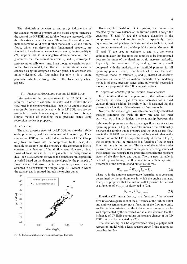
A. Overview The main pressure states of the LP EGR loop are the turbine
outlet pressure dtp and the compressor inlet pressure ucp . For a single-loop EGR system, which does not have a LP EGR loop, only fresh air flows into the compressor. In this case, it is possible to assume that the pressure at the compressor inlet is constant or a function of the air flow rate. However, mixed flows of fresh air and LP EGR gas enter the compressor in dual-loop EGR systems for which the compressor inlet pressure is varied based on the dynamics developed by the principle of flow balance. Likewise, the turbine outlet pressure can be assumed to be constant for a single-loop EGR system in which the exhaust gas is emitted through the turbine outlet.
Fig. 3. Turbine outlet pressure versus exhaust gas flow rate.
However, for dual-loop EGR systems, the pressure is affected by the flow balance at the turbine outlet. Though the equations (3) and (4) are the pressure dynamics in the compressor inlet and turbine outlet, respectively, these equations are not practical because variables such as cT and
cW are not measured in a dual-loop EGR system. Moreover, if (3) and (4) are used to estimate dtp and ucp , the whole estimation algorithm becomes too complex to be implemented because the order of the algorithm would increase markedly. Physically, the variations of dtp and ucp are very small compared with the intake/exhaust manifold pressure for all operating points. Hence, it is beneficial to use the static regression model to estimate dtp and ucp instead of observer dynamics or recursive estimation methods. The modeling methods of these pressure states using polynomial regression models are proposed in the following subsections.
B. Regression Modeling of the Turbine Outlet Pressure It is intuitive that as the pressure at the turbine outlet
increases, the exhaust gas flow rate increases for a fixed exhaust throttle position. To begin with, it is assumed that the pressure is a function of the exhaust gas flow rate only.
Note that the exhaust gas flow rate can be easily calculated through summing the fresh air flow rate and fuel rate:
out air fW W W= + . Fig. 3 depicts the relationship between the turbine outlet pressure and the exhaust gas flow rate at various operating points. In Fig. 3, the circles indicate the relationship between the turbine outlet pressure and the exhaust gas flow rate in the HP EGR operations only, and the × marks denote the relationship in the LP EGR operations only. As seen in Fig. 3, the assumption that the pressure is a function of the exhaust flow rate only is not correct. The ratio of the turbine outlet pressure and ambient pressure is the primary driving source of the exhaust flow because these pressures represent the pressure states of the flow inlet and outlet. Then, a new variable is defined by combining the flow rate term with temperature difference of the flow inlet and outlet, as follows:
_ ,out corr out dt aW W T T-@ (22)
where aT is the ambient temperature (regarded as a constant) determined by the environment in which the engine operates. Then, it is proposed that the turbine outlet pressure be defined as a function of _corr outW as described in (23).
_( ).dt out corrp f W= (23)
Equation (23) means that dtp is a function of the exhaust flow rate and a square root of the difference of the turbine outlet and ambient temperature, not a function of the flow rate only. As Fig. 4 demonstrates that the turbine outlet pressure can be well represented by the corrected variable, it is deduced that the influence of LP EGR operations on pressure change in the LP EGR loop can be indicated by (23).
The relationship can be approximated using a polynomial regression model with a least squares curve fitting method as described in (24).

7
Fig. 4. Turbine outlet pressure versus the corrected exhaust gas flow rate.
2
_ _0.7584( ) 0.7853( ) 103.08.ˆdt out corr out corrp W W= + + (24) The R2 of the regression model is 0.9766, which indicates a good fit.
C. Regression Modeling of the Compressor Inlet Pressure In the same manner, the compressor inlet pressure can be
modelled using the information of the fresh air flow rate and compressor inlet temperature. For the compressor inlet pressure, it is clear that the fresh air flow rate increases as the pressure decreases for a fixed intake throttle position in a single-loop EGR system. Although the LP EGR flow is added to the fresh air flow rate at the compressor inlet, which establishes a slightly different relationship between the flow and the pressure in a dual-loop EGR system, the compressor inlet pressure is relevant to the fresh air flow rate. It should be noted that the fresh air flow rate can also be measured by sensors in the production engine. First, assume that the pressure is a function of the fresh air flow rate only. In Fig. 5, the compressor inlet pressure is plotted against the fresh air flow rate for various operating points. As for the HP EGR operations (circles), the compressor inlet pressure is inversely proportional to the fresh air flow rate as expected because this case is equivalent to an engine with a single EGR system. However, it is difficult to determine a similar relationship with the LP EGR operations (× marks). In order to determine an appropriate relationship for both the HP EGR and LP EGR operations, the compressor inlet pressure is assumed to be a function of the corrected air flow rate, which reflects the effect of temperature change due to LP EGR operations, as follows:
_( ),uc air corrp f W= (25)
where _air corr air uc aW W T T-@ . Through considering the temperature terms ucT and aT , it is expected that the effects of the LP EGR rate on ucp can be indicated using (25).
Fig. 5. Compressor inlet pressure versus fresh air flow rate.
Fig. 6. Compressor inlet pressure versus the corrected air flow rate.
Fig. 6 demonstrates that it is reasonable that ucp is a function of the corrected air flow rate. The relationship can also be approximated using a second-order regression model, as follows:
2_ _5.1351( ) 0.7751( ) 101.14,ˆuc air corr air corrp W W= - + + (26)
whose R2 is 0.9845. Note that it is assumed that the intake and exhaust throttles of
the engine are fixed in this study. However, the suggested modeling approach can be extended to the cases of variable throttle positions by including effective area term of the throttle in the regressor.
D. Experimental Verification The regression models for the pressure states of the LP EGR
loop were experimentally validated based on the 6 L heavy-duty diesel engine with a dual-loop EGR and VGT. In order to prove that the regression models work well without a recursive algorithm, the verification was undertaken for various operating points.

8
Fig. 7. Estimation results of the turbine outlet pressure.
Fig. 8. Estimation results of the compressor inlet pressure.
Figs. 7 and 8 compare the estimated data from the regression
models in (24) and (26) with the experimental data under the broad operating conditions. The maximum steady state error was less than 0.65% for both pressure states. Consequently, the pressure states at the turbine outlet and compressor inlet were modelled precisely using the simple regression models and the information already available on the flow rate and temperature at the corresponding locations. These regression models will be used in the implementation of the exhaust pressure observer designed in the previous section.
V. EXPERIMENTAL VERIFICATION OF THE FINAL EXHAUST PRESSURE OBSERVER
A. Observer with LP EGR Regression Models In this section, the estimation performance of the exhaust
pressure observer with the LP EGR pressure models is evaluated experimentally. The entire structure of the observer is depicted in Fig. 9. In Fig. 9, the current values for the compressor inlet pressure and turbine outlet pressure are computed from the polynomial regressions designed in the previous section. With these pressure models added to the observer, a more practical estimation algorithm for the exhaust pressure is implemented with less sensor information. In fact, the accuracy of differential pressure values across the LP EGR is crucial in estimating the LP EGR flow rate, and using the steady compressible orifice equation further deteriorates the estimation accuracy of it [28, 32]. However, if errors of the flow models are bounded, and the sliding mode gain is sufficiently high, the effect of the model uncertainties can be eliminated. In other words, while using the pressure regression models and the steady orifice equation has adverse effects on
Fig. 9. Final exhaust pressure observer structure. the model accuracy of the LP EGR flow ˆ
LPegrW , it does not affect the convergence stability of the observer because the uncertainty is canceled by the sliding mode observer gain 2L . Then, the mass flow rates are calculated using model equations (5)–(8) with other measurements. Finally, the exhaust manifold pressure is estimated by the observer. The final exhaust pressure observer equipped with the LP EGR pressure models is implemented as described in (27):
( )( )
( )
1
1 1 2 1
2
3 1 4 1
ˆ ˆˆ ˆ
sgn ,ˆ ˆ( )ˆ ˆ
sgn ,
i air LPegr HPegr e i
x e i f HPegr t
p k W W W k p
L L
p k k p W W W
L L
e e
e e
= + + -
+ +
= + - -
+ +
&
& (27)
where ( )ˆ ˆ ,ˆ ˆLPegr LPegr uc dtW W p p= and ( )ˆ ˆ ,ˆ ˆt t x dtW W p p= .
B. Experimental Setup A heavy-duty 6-cylinder 6 L diesel engine was used for the
experimental validation of the observer; it is depicted in Fig. 10. The LP EGR loop was added to the original single EGR system for the dual-loop EGR operations. The sensor information already available on the production engine, e.g. engine speed, fuel rate, fresh air flow rate, and intake pressure, was acquired by the engine control unit (ECU) in real time. Additional pressure sensors were installed at different locations including the exhaust manifold in order to validate the observer and pressure models. MicroAutobox dSPACE 1401 was used to run the observer algorithm with the pressure models and to process the signals from all sensors.
Fig. 10. Test engine setup.
0 100 200 300 400 500 600 700
104
106
108
110
112
114
time(s)
turb
ine
outle
t pre
ssur
e (k
Pa)
estimatedmeasured
0 100 200 300 400 500 600 70097
98
99
100
101
102
103
time(s)
com
pres
sor i
nlet
pre
ssur
e (k
Pa)
estimatedmeasured

9
C. Steady State Verification The developed observer and the regression models of the
turbine outlet and compressor inlet pressure states were validated with the test engine. The verification in steady states was conducted under the conditions described in Figs. 11(a) and 11(b). At each point of 10 seconds, the engine speed, injected fuel rate, positions of EGR valves, and VGT duty were maintained constant. The measured data of the exhaust pressure were steady state values at the corresponding point. This verification was conducted in order to determine whether the estimated values of the observer would rapidly converge to near the measured values even though the operating points were changed significantly. Note that because the reference engine in this research is a heavy-duty diesel engine, the engine speed is generally fixed during operation, and the fuel rate is determined in accordance with the desired engine load. Here, the engine speed is fixed at either 1400 or 1800 RPM. The experimental results are presented in Fig. 11(c). The maximum steady state error was less than 1.6%. Although the conditions for the verification were numerous and changed abruptly, the estimated pressure values quickly converged to near the true values. Note that the change in LP EGR valve position had little effect on the exhaust pressure here because the engine load was relatively low with the HP EGR valve closed during the LP EGR operations [15]; thus, the exhaust pressure was mostly dependent on the VGT duty.
(a)
(b)
(c)
Fig. 11. Exhaust pressure estimation in steady state conditions: (a) fuel rate, (b) EGR valve positions and VGT duty, and (c) exhaust pressure.
(a)
(b)
(c)
Fig. 12. Exhaust pressure estimation in transient scenario (i): (a) fuel rate, (b) EGR valve positions and VGT duty, and (c) exhaust pressure.
D. Transient State Verification The observer performance was also verified for transient
conditions that contain various load conditions. The experimental evaluations were undertaken in extremely transient conditions called the non-road transient cycle (NRTC) mode for heavy-duty diesel engines. The operating conditions including the fuel rate, EGR valve positions, and VGT duty were continuously varied during the transient tests, while the engine speed was maintained at near 1800 RPM. It should be noted that the NRTC mode includes the combined operations of both EGR valves. The transient validations were performed for two different scenarios: (i) low/medium engine loads with a full opening of the LP EGR valve and (ii) high engine loads with a large sweep of the LP EGR valve position. The estimation results for scenario (i) are described in Fig. 12.
It is clearly seen that the estimated values follow the true values well, as expected from the stability proof of the observer. The maximum estimation error was less than 6%. Another experiment was conducted under more severe conditions (scenario (ii)) where the engine load was significantly higher and the LP EGR valve positions were considerably and continuously varied. The estimation results are presented in Fig. 13.
0 50 100 150 200 250 300 350 400 450
time(s)
0
20
40
60
80
100
posi
tion,
dut
y (%
)
HP EGR valve posLP EGR valve posVGT duty
fuel
rate
(kg/
s)po
sitio
n, d
uty
(%)
0 10 20 30 40 50 60 70
time(s)
1
1.5
2
exha
ust p
ress
ure
(Pa)
105
estimatedmeasured

10
(a)
(b)
(c)
Fig. 13. Exhaust pressure estimation in transient scenario (ii): (a) fuel rate, (b) EGR valve positions and VGT duty, and (c) exhaust pressure.
It should be noted that most values of the fuel rate and
exhaust pressure were higher than those of scenario (i) due to the higher engine loads. The mean estimation error was slightly larger for scenario (ii) than for scenario (i), but the maximum error remained less than 6%. Considering that scenario (ii) contained severe operating conditions, the experimental results verify the observer performance well.
VI. CONCLUSION In this paper, an exhaust pressure observer for diesel engines
with a dual-loop EGR and VGT was designed with limited measurements. In order to overcome the lack of sensors for the pressure states in the LP EGR loop, polynomial regression models for the compressor inlet and turbine outlet pressures were proposed, and the model accuracy was validated experimentally with the test engine. The developed pressure models have simple and intuitive structures that can be utilized for various control applications in diesel engines with dual-loop EGR systems. The proposed exhaust pressure observer with the regression models was experimentally validated using a test engine with a dual-loop EGR and VGT for numerous operating points covering both steady state and transient conditions. The results demonstrate that the observer is robust to model uncertainties and sufficiently accurate to replace the exhaust pressure sensor. For future work, research on developing adaptive algorithms for the system parameters will be
conducted in order to manage changes in the environmental conditions.
ACKNOWLEDGMENT This work was supported in part by the Ministry of Science,
ICT and Future Planning (MSIP), Korea, under the Information Technology Research Center (ITRC) support program (grant IITP-2016-H8601-16-1005) supervised by the Institute for Information & Communications Technology Promotion (IITP), the BK21 plus program, and the National Research Foundation of Korea (NRF) grant funded by the Korean government (MSIP) (grant 2010-0028680).
REFERENCES [1] F. Yan and J. Wang, "Control of diesel engine dual-loop EGR
air-path systems by a singular perturbation method," Control Engineering Practice, vol. 21, pp. 981-988, 2013.
[2] J. Wang, "Air fraction estimation for multiple combustion mode diesel engines with dual-loop EGR systems," Control Engineering Practice, vol. 16, pp. 1479-1486, 2008.
[3] F. Castillo, E. Witrant, V. Talon, and L. Dugard, "Simultaneous air fraction and low-pressure EGR mass flow rate estimation for diesel engines," in 5th IFAC Symposium on System Structures and Control, 2013.
[4] M. Ammann, N. P. Fekete, L. Guzzella, and A. Glattfelder, "Model-based control of the VGT and EGR in a turbocharged common-rail Diesel engine: theory and passenger car implementation," SAE Technical Paper2003.
[5] H. Jin, S. Choi, and H. Jung, "Simplified Multiple Sliding Mode Transient Control with VGT and EGR Diesel Engine," SAE Technical Paper2013.
[6] I. Kolmanovsky, P. Morall, M. Van Nieuwstadt, and A. Stefanopoulou, "Issues in modelling and control of intake flow in variable geometry turbocharged engines," Chapman and Hall CRC research notes in mathematics, pp. 436-445, 1999.
[7] D. Upadhyay, "Modeling and Model based Control Design of the VGT-EGR System for Intake Flow Regulation in Diesel Engines," Ph.D. dissertation, The Ohio State University, Ohio, USA, 2001.
[8] J. Wahlström, "Control of EGR and VGT for emission control and pumping work minimization in diesel engines," Ph.D. dissertation, Linköping University, Sweden, 2006.
[9] J. Wang, "Hybrid robust air-path control for diesel engines operating conventional and low temperature combustion modes," Control Systems Technology, IEEE Transactions on, vol. 16, pp. 1138-1151, 2008.
[10] Y. Yoon, "A Study of Turbocharged Diesel Engine Modeling and Robust Model Based Sliding Mode Controller Design," Master's Thesis, KAIST, Daejeon, Korea, 2011.
[11] M. Jankovic and I. Kolmanovsky, "Constructive Lyapunov control design for turbocharged diesel engines," Control Systems Technology, IEEE Transactions on, vol. 8, pp. 288-299, 2000.
[12] A. G. Stefanopoulou, I. Kolmanovsky, and J. S. Freudenberg, "Control of variable geometry turbocharged diesel engines for reduced emissions," Control Systems Technology, IEEE Transactions on, vol. 8, pp. 733-745, 2000.
[13] M. Van Nieuwstadt, I. Kolmanovsky, P. Moraal, A. Stefanopoulou, and M. Jankovic, "EGR-VGT control schemes: experimental comparison for a high-speed diesel engine," IEEE Control Systems, vol. 20, pp. 63-79, 2000.
[14] S. Kim, H. Jin, and S. Choi, "Pressure and flow based control of a turbocharged diesel engine air-path system equipped with dual-loop EGR and VGT," in American Control Conference (ACC), 2014, 2014, pp. 1493-1498.
[15] S. Kim, S. Choi, and H. Jin, "Pressure model based coordinated control of VGT and dual-loop EGR in a diesel engine air-path system," International Journal of Automotive Technology, vol. 17, pp. 193-203, 2016.
[16] J. Fredriksson and B. Egardt, "Estimating exhaust manifold pressure in a turbocharged diesel engine," in Control Applications, 2002.

11
Proceedings of the 2002 International Conference on, 2002, pp. 701-706.
[17] Y.-Y. Wang and I. Haskara, "Exhaust Pressure Estimation and Its Application to Detection and Isolation of Turbocharger System Faults for Internal Combustion Engines," Journal of Dynamic Systems, Measurement, and Control, vol. 134, p. 021002, 2012.
[18] P. Andersson, "Comparison of two exhaust manifold pressure estimation methods," in The third computer science and engineering system conference, Linkopin, Sweden, 2001.
[19] P. Andersson and L. Eriksson, "Exhaust manifold pressure estimation on a turbocharged SI-engine with wastegate," in In IFAC Workshop-Advances in Automotive Control, 2001.
[20] P. M. Olin, "A mean-value model for estimating exhaust manifold pressure in production engine applications," SAE Technical Paper2008.
[21] J. H. Buckland, M. Jankovic, J. Grizzle, and J. Freudenberg, "Estimation of exhaust manifold pressure in turbocharged gasoline engines with variable valve timing," in ASME 2008 Dynamic Systems and Control Conference, 2008, pp. 315-321.
[22] F. Chiara, M. Canova, and Y.-Y. Wang, "An exhaust manifold pressure estimator for a two-stage turbocharged diesel engine," in American Control Conference (ACC), 2011, 2011, pp. 1549-1554.
[23] K. Siokos, R. Koli, R. Prucka, J. Schwanke, and S. Jade, "Physics-Based Exhaust Pressure and Temperature Estimation for Low Pressure EGR Control in Turbocharged Gasoline Engines," SAE Technical Paper 0148-7191, 2016.
[24] J. Lee, H. Lee, and M. Sunwoo, "Nonlinear sliding mode observer for exhaust manifold pressure estimation in a light-duty diesel engine," International Journal of Automotive Technology, vol. 15, pp. 377-386, 2014.
[25] H. Jin, S. Choi, and S. Kim, "Design of a compressor-power-based exhaust manifold pressure estimator for diesel engine air management," International Journal of Automotive Technology, vol. 15, pp. 191-201, 2014.
[26] F. Castillo, E. Witrant, L. Dugard, and V. Talon, "Exhaust Manifold Pressure Estimation Diesel Equipped with a VGT Turbocharger," SAE Technical Paper2013.
[27] G. Stratakis, D. Psarianos, and A. Stamatelos, "Experimental investigation of the pressure drop in porous ceramic diesel particulate filters," Proceedings of the Institution of Mechanical Engineers, Part D: Journal of Automobile Engineering, vol. 216, pp. 773-784, 2002.
[28] F. Liu and J. Pfeiffer, "Estimation Algorithms for Low Pressure Cooled EGR in Spark-Ignition Engines," SAE International Journal of Engines, vol. 8, pp. 1652-1659, 2015.
[29] J. Wahlström and L. Eriksson, "Modelling diesel engines with a variable-geometry turbocharger and exhaust gas recirculation by optimization of model parameters for capturing non-linear system dynamics," Proceedings of the Institution of Mechanical Engineers, Part D: Journal of Automobile Engineering, vol. 225, pp. 960-986, 2011.
[30] J. Chauvin, G. Corde, N. Petit, and P. Rouchon, "Motion planning for experimental airpath control of a diesel homogeneous charge-compression ignition engine," Control Engineering Practice, vol. 16, pp. 1081-1091, 2008.
[31] H. K. Khalil and J. Grizzle, Nonlinear systems vol. 3: Prentice hall New Jersey, 1996.
[32] R. Kiwan, A. G. Stefanopoulou, J. Martz, G. Surnilla, I. Ali, and D. J. Styles, "Effects of Differential Pressure Measurement Characteristics on Low Pressure-EGR Estimation Error in Si-Engines," 8th IFAC Symposium on Advances in Automotive Control AAC 2016, vol. 49, pp. 722-729, 2016.
Sooyoung Kim received his B.S. and M.S. degrees in mechanical engineering from Korea Advanced Institute of Science and Technology (KAIST), Daejeon, Korea, where he is currently working toward his Ph.D. in mechanical engineering.
His current research interests include control of diesel engines and dual clutch transmissions.
Hyomin Jin received his B.S. in mechanical engineering from Chonbuk National University, Jeonju, Korea, and his M.S. and Ph.D. in mechanical engineering from KAIST, Daejeon, Korea in 2014.
He is currently a Senior Research Engineer with the Engine Control Team in Hyundai Autron, Pangyo, Korea. His
research interests include diesel engine control and emission reduction technologies.
Seibum B. Choi (M’09) received his B.S. in mechanical engineering from Seoul National University, Seoul, Korea, his M.S. in mechanical engineering from KAIST, Daejeon, Korea, and his Ph.D. in control from the University of California, Berkeley, CA, USA, in 1993.
From 1993 to 1997, he was involved in the development of automated vehicle control systems at the Institute of
Transportation Studies, University of California. Through 2006, he was with TRW, Livonia, MI, USA, where he was involved in the development of advanced vehicle control systems. Since 2006, he has been faculty in the Mechanical Engineering Department, KAIST, Korea. His current research interests include fuel-saving technology, vehicle dynamics and control, and active safety systems.
Prof. Choi is a Member of the American Society of Mechanical Engineers, the Society of Automotive Engineers, and the Korean Society of Automotive Engineers.


![[Luenberger] Investment Science(BookZZ.org)](https://img.dokumen.tips/doc/110x75/55cf9482550346f57ba2782c/luenberger-investment-sciencebookzzorg.jpg)