Embed Size (px)
Citation preview

Executive Tower Sean Howard Structural Technical Assignment 3
Lateral System Analysis and Confirmation Design
Executive Summary
In this report, a detailed analysis of the lateral forces was performed in efforts to examine and test the lateral resisting framing system for the Executive Tower. This report is divided into three sections. Section one is a second look at the wind and seismic forces initially examined in technical report 1. The wind and seismic were checked, recalculated and compared using charts to find which scenarios govern over the other. The second section explains the structural systems in place and how they coordinate with each other. It was assumed, the besides the shear being the main lateral resisting system, that a study of six moment frames creating the perimeter beam and exterior columns of the building would be beneficial in studying the building. Finally a detail analysis of the frames and shear walls were preformed to check stresses, flexural and drift through the use of STAAD and RAM analysis programs. This technical report looks in depth lateral systems and the drifts that are resulted from the combined lateral and gravity loads. Hand calculations of spot checks at critically stress locations found all columns to be able to withstand the combined loads. The check of the shears at the worse case scenario found the wall sections and reinforcement to be adequate. From the technical report, the lateral forces for the Executive Tower were checked and corrected to still be used in future examinations.
1
Introduction
Executive Tower is a 12 story structure consisting of primarily cast-in-place concrete. The framing system is an 8” two-way concrete flat slab with 8” drop panels at column locations and an additional 3 ½” thickened slab acting as an edge for the entire perimeter of the building.
Report Layout • Lateral load cases and controlling conditions • Existing lateral systems; shears walls, and moment frames • Distribution of later loads to resisting system • Analysis of lateral structures • Appendix A – Seismic and Wind Calculations • Appendix B – Load Distribution • Appendix C – Story Drift • Appendix D – Column Spot Check • Appendix E – Shear Wall Spot Check
Loads
All loads are in accordance ASCE7-02 and assumes a 20 psf addition live load be assumed for partitions. Live Loads Office 80 psf + 20 psf = 100 psf Dead Loads Concrete 124 psf Curtain 12 psf Sprinkler 5 psf MEP 5 psf Finishes 10 psf
2

Lateral Load Summary
Wind
The wind analysis were taken from Technical Assignment 1 and checked to be properly used in this report using ASCE 7-02. Executive Tower is set in the middle of downtown Washington DC with several buildings of similar height near by. It was for this reason an Expose B and case 2 were used to calculate the wind pressures applied to the Executive Tower. The kz values were found in Table 6-3 of ASCE 7-02 but were calculated using an excel spreadsheet for the mid-floor intervals using eq. 2 on Table 6-3, kz = 2.01(z/zg)2/ά. In the chart below the new heights for Z can be seen along with the calculated pressures for the N-S and E-W directions. The extent of the wind analysis including Gust Factor calculations can be found in Appendix A.
3

Seismic
Like the wind analysis, the seismic forces for this report were taken from Technical Assignment 1 and recheck for accurate results. For this report, the seismic loads were found to be less than in Tech 1. The seismic loads are in accordance with ASCE 7-02. An in-depth calculation of the structures dead load for the seismic calculation is displayed in Appendix B along with hand calculations. Including the drop panels and edge beams spread over the total area of the floor. A full description of the story forces can be seen below calculated using a spreadsheet.
Lateral Comparisons
The story forces and wind pressures were converted into the linear pressure across the length of the building to compare which forces will govern in which directions. It was found the seismic loads controlled in the upper floors while the wind governing factors the lower floors.
4
Lateral Resisting System
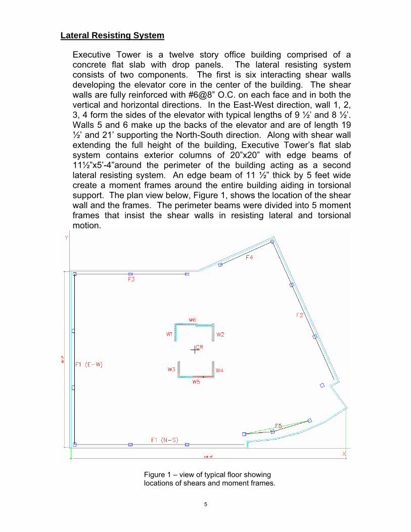
Executive Tower is a twelve story office building comprised of a concrete flat slab with drop panels. The lateral resisting system consists of two components. The first is six interacting shear walls developing the elevator core in the center of the building. The shear walls are fully reinforced with #6@8” O.C. on each face and in both the vertical and horizontal directions. In the East-West direction, wall 1, 2, 3, 4 form the sides of the elevator with typical lengths of 9 ½’ and 8 ½’. Walls 5 and 6 make up the backs of the elevator and are of length 19 ½’ and 21’ supporting the North-South direction. Along with shear wall extending the full height of the building, Executive Tower’s flat slab system contains exterior columns of 20”x20” with edge beams of 11½”x5’-4”around the perimeter of the building acting as a second lateral resisting system. An edge beam of 11 ½” thick by 5 feet wide create a moment frames around the entire building aiding in torsional support. The plan view below, Figure 1, shows the location of the shear wall and the frames. The perimeter beams were divided into 5 moment frames that insist the shear walls in resisting lateral and torsional motion.
Figure 1 – view of typical floor showing locations of shears and moment frames.
5

Distribution
To the start the load distribution, the continuous edge beam around the perimeter of the building was divided up into 6 frames for simplicity and model in STAAD. A 100 kip unit load was applied to each frame at each floor level. By dividing the corresponding unit by the deflection at that node resulted in the rigidity of the structure for each level. The rigidity for the shear walls were computed through spreadsheets. At frames 2, 4, and 5, the applied forces from wind and seismic were skewed from the frame directions. For this, it was assumed that a proportion of the rigidity would act in each direction equal to sine or cosine of the angle. However, this method was not used when accounting for torsion. The full rigidity was used times the perpendicular to the center of rigidity.
Below are the controlling story forces and shear forces organized by level.
6
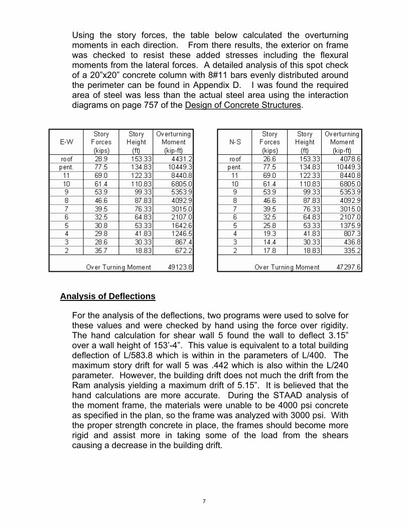
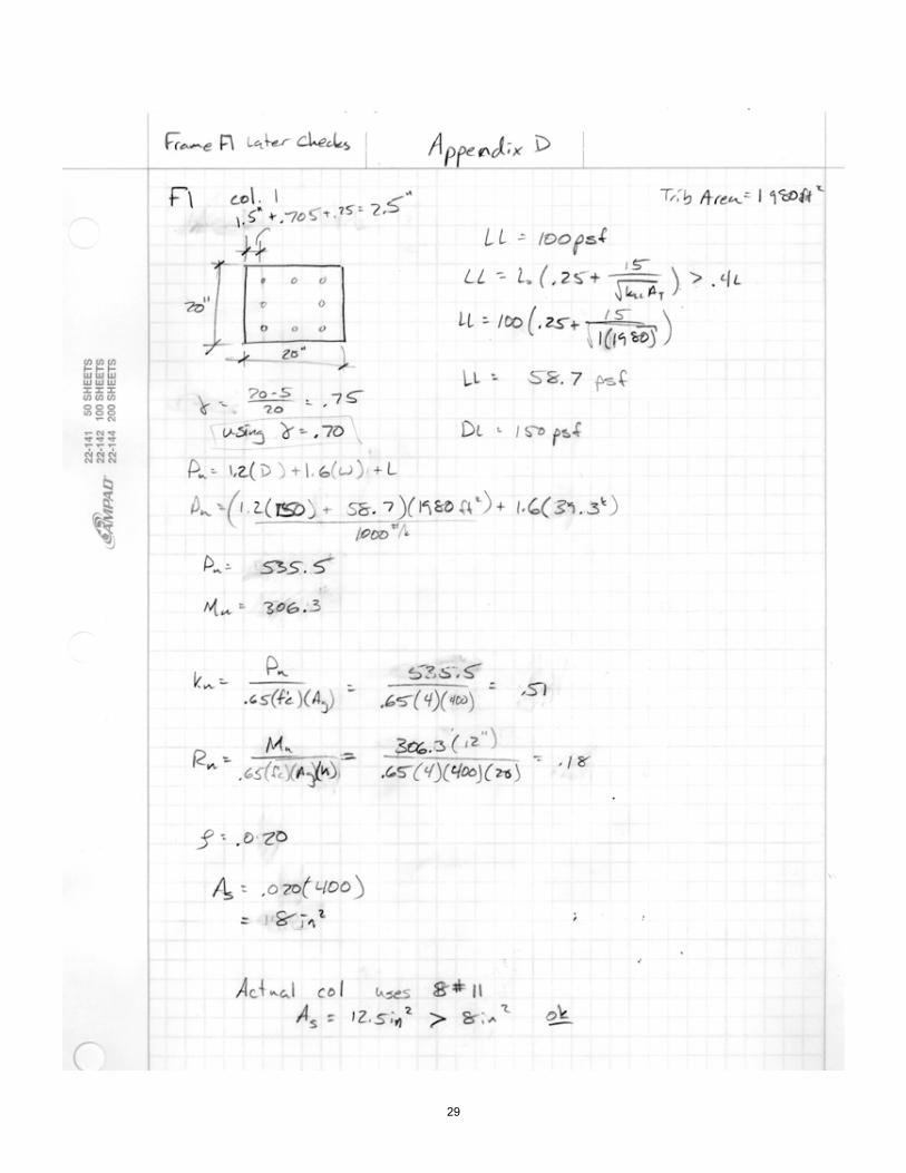
Using the story forces, the table below calculated the overturning moments in each direction. From there results, the exterior on frame was checked to resist these added stresses including the flexural moments from the lateral forces. A detailed analysis of this spot check of a 20”x20” concrete column with 8#11 bars evenly distributed around the perimeter can be found in Appendix D. I was found the required area of steel was less than the actual steel area using the interaction diagrams on page 757 of the Design of Concrete Structures.
Analysis of Deflections
For the analysis of the deflections, two programs were used to solve for these values and were checked by hand using the force over rigidity. The hand calculation for shear wall 5 found the wall to deflect 3.15” over a wall height of 153’-4”. This value is equivalent to a total building deflection of L/583.8 which is within in the parameters of L/400. The maximum story drift for wall 5 was .442 which is also within the L/240 parameter. However, the building drift does not much the drift from the Ram analysis yielding a maximum drift of 5.15”. It is believed that the hand calculations are more accurate. During the STAAD analysis of the moment frame, the materials were unable to be 4000 psi concrete as specified in the plan, so the frame was analyzed with 3000 psi. With the proper strength concrete in place, the frames should become more rigid and assist more in taking some of the load from the shears causing a decrease in the building drift.
7

Conclusion Through this report the lateral systems were found to be sufficient to withstand the lateral loads. The spot checks of the shear wall 5 in Appendix E show the wall with the worst case load is able to satisfy the both shear and flexural. The column in Frame 1 was analyzed to using combined loads and the interaction diagram. The reinforcement in this member was found be to be adequate for combine flexure and compressive stresses. The lateral deflections of the shear walls and frames were found to be accurate through hand calculation but will require further investigation to insure the rigidity of the moment frames are acceptable. From the technical report, the lateral forces for the Executive Tower were checked and corrected to still be used in future examinations.
8

Appendix A Seismic and Wind
9

10

11

12

Table 6-2zmin 30 V 90 F 6-1c 0.30 b 0.05
l 320 68.7694659e 0.33 n1 = f = 0.67424168b 0.45 6.91520264a 0.142857143 6.53951857
L 92 13.8908395B 145gQ 3.4 Rh 0.13415306gv 3.4 RB 0.14122476z = 0.6h = 91.998 z>30? RL 0.06939862
Lz = l(z/33)e = 450.372081 TRUE
Iz = c(33/z)1/6 = 0.252877689 91.998= 0.82032966
N1 = n1Lz/Vz = 4.41561707= 0.05489361= 0.10817781
4.094435435
0.831964978
hh = 4.6n1h/Vz =hB = 4.6n1B/Vz =
hL = 15.4n1L/Vz =
Gf = 0.925(((1+1.7Iz(gQ2Q2+gR
2R
2)1/2)/(1+1.7gvIz)) =
Ri = (1/hi)-(1/(2h2))(1-e-2h)
Rn = 7.47N1/(1+10.3N1)5/3
R = ((1/b)RnRhRB(0.53+0.47RL)1/2
gR = (2ln(3600n1))1/2+0.577/(2ln(3600n1))
1/2 =
Q = (1/(1+0.63((B+h)/Lz)0.63))1/2
Vz = b (z/33)aV(88/60) =
flexible buildings ( f < 1.0 Hz) (6.5.8): Gf
use
Gust Factor for East West Direction
13
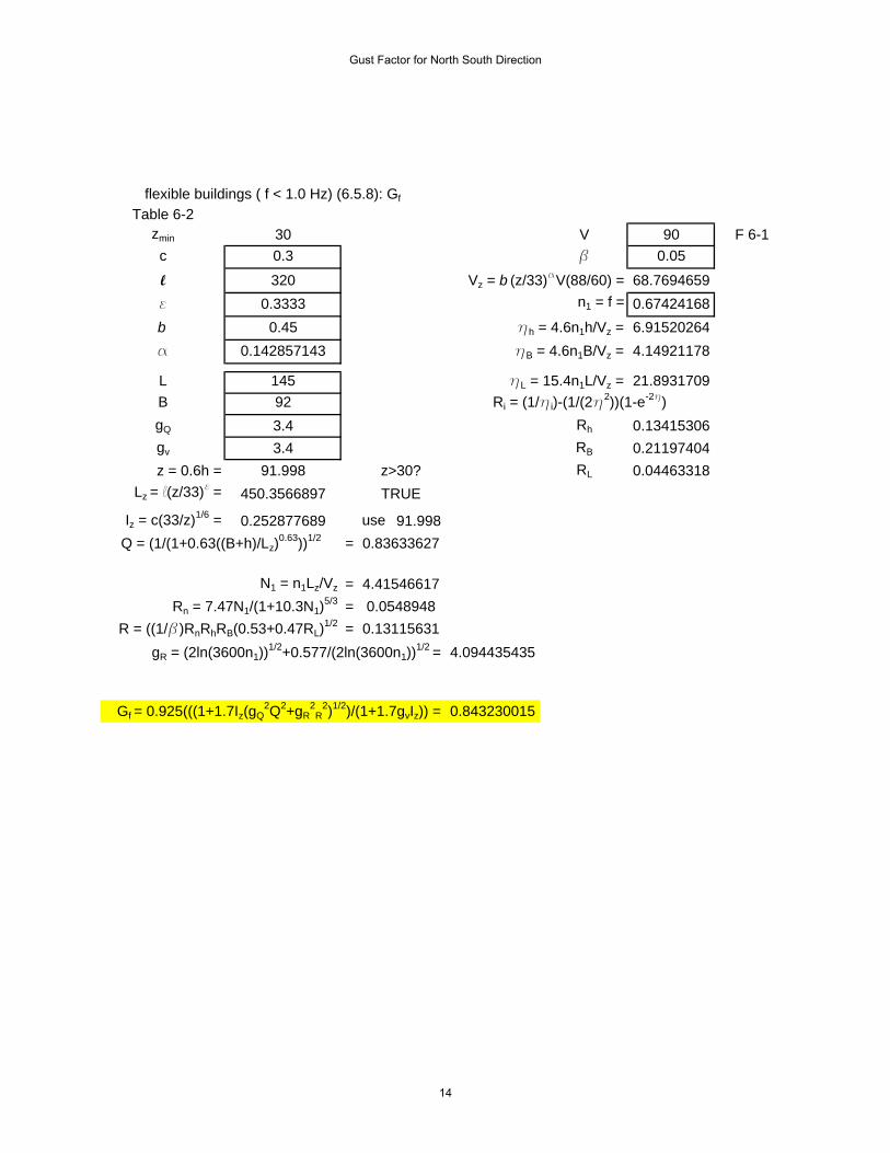
Table 6-2zmin 30 V 90 F 6-1c 0.3 b 0.05
l 320 68.7694659e 0.3333 n1 = f = 0.67424168b 0.45 6.91520264a 0.142857143 4.14921178
L 145 21.8931709B 92gQ 3.4 Rh 0.13415306gv 3.4 RB 0.21197404z = 0.6h = 91.998 z>30? RL 0.04463318
Lz = l(z/33)e = 450.3566897 TRUE
Iz = c(33/z)1/6 = 0.252877689 91.998= 0.83633627
N1 = n1Lz/Vz = 4.41546617= 0.0548948= 0.13115631
4.094435435
0.843230015
flexible buildings ( f < 1.0 Hz) (6.5.8): Gf
Vz = b (z/33)aV(88/60) =
hh = 4.6n1h/Vz =hB = 4.6n1B/Vz =
hL = 15.4n1L/Vz =Ri = (1/hi)-(1/(2h2))(1-e-2h)
Gf = 0.925(((1+1.7Iz(gQ2Q2+gR
2R
2)1/2)/(1+1.7gvIz)) =
Q = (1/(1+0.63((B+h)/Lz)0.63))1/2
Rn = 7.47N1/(1+10.3N1)5/3
R = ((1/b)RnRhRB(0.53+0.47RL)1/2
gR = (2ln(3600n1))1/2+0.577/(2ln(3600n1))
1/2 =
use
Gust Factor for North South Direction
14

Appendix B Load Distribution
15

16

17

Lateral h Wall 1 Wall 2 Wall 3 Wall 4 Wall 5 Wall 6 F1 F2 F2 F2 F3 F4 F4 F4 F5 F5 F5Rigidity (ft) (E-W) (E-W) (E-W) (E-W) (N-S) (N-S) (E-W) (E-W) (N-S) (N-S) (E-W) (N-S) (E-W) (N-S) (E-W) (N-S)
roof 153.3 2.6 2.6 2.1 2.1 20.9 27.4 8.9 9.2 8.4 3.7 5.9 3.3 1.3 3.0 9.8 2.0 9.6 30.0 70.512 133.8 3.8 3.8 3.2 3.2 31.3 41.0 10.0 10.2 9.3 4.2 6.6 3.7 1.5 3.4 11.1 2.3 10.9 37.2 97.211 122.3 5.0 5.0 4.1 4.1 40.8 53.5 11.1 11.5 10.5 4.7 7.4 4.2 1.7 3.8 12.7 2.6 12.4 44.3 122.610 110.8 6.8 6.8 5.6 5.6 54.7 71.5 12.6 13.0 11.8 5.3 8.4 4.8 2.0 4.4 14.6 3.0 14.3 54.1 158.69 99.33 9.4 9.4 7.7 7.7 75.5 98.7 14.5 14.9 13.6 6.1 9.7 5.6 2.3 5.1 17.1 3.6 16.7 68.2 211.98 87.83 13.5 13.5 11.2 11.2 108.4 141.6 17.1 17.5 15.9 7.1 11.4 6.6 2.7 6.0 20.4 4.2 20.0 89.4 294.57 76.33 20.6 20.6 16.9 16.9 163.4 212.8 20.7 21.0 19.2 8.6 13.8 8.1 3.3 7.4 25.3 5.3 24.7 123.5 430.76 64.83 33.4 33.4 27.6 27.6 262.0 340.3 26.2 26.4 24.1 10.7 17.4 10.5 4.3 9.6 32.8 6.8 32.1 183.4 672.25 53.33 59.6 59.6 49.2 49.2 457.3 590.7 36.2 35.6 32.5 14.5 23.9 14.8 6.0 13.5 46.7 9.7 45.7 302.0 1145.64 41.83 121.8 121.8 100.6 100.6 898.0 1149.3 56.8 53.7 49.0 21.9 37.0 24.0 9.8 21.9 73.2 15.2 71.6 575.6 2199.73 30.33 309.1 309.1 256.3 256.3 2098.3 2636.8 113.6 101.2 92.4 41.2 73.5 50.5 20.5 46.1 146.0 30.3 142.8 1387.8 5038.72 18.83 1164.6 1164.6 976.7 976.7 6411.7 7750.7 450.5 367.7 335.8 149.7 291.5 217.9 88.6 199.1 574.0 119.3 561.5 5276.7 15364.1
ΣR
18

story storyE-W forces shear prop. Shear prop. Shear prop. Shear prop. Shear prop. Force prop. Force prop. Force prop. Force
(kips) (kips) (%) (kips) (%) (kips) (%) (kips) (%) (kips) (%) (kips) (%) (kips) (%) (kips) (%) (kips)roof 28.9 28.9 0.085 2.5 0.085 2.5 0.070 2.0 0.070 2.0 0.297 8.57 0.197 5.68 0.045 1.29 0.068 1.96pent. 77.5 106.4 0.104 11.0 0.104 11.0 0.085 9.1 0.085 9.1 0.269 20.84 0.178 13.76 0.040 3.14 0.062 4.8111 69.0 175.4 0.114 20.0 0.114 20.0 0.094 16.4 0.094 16.4 0.251 17.31 0.167 11.54 0.039 2.66 0.060 4.1110 61.4 236.8 0.125 29.6 0.125 29.6 0.103 24.4 0.103 24.4 0.233 14.30 0.155 9.53 0.036 2.22 0.056 3.449 53.9 290.7 0.138 40.0 0.138 40.0 0.113 32.9 0.113 32.9 0.213 11.47 0.142 7.67 0.033 1.80 0.052 2.818 46.6 337.3 0.152 51.1 0.152 51.1 0.125 42.1 0.125 42.1 0.191 8.92 0.128 5.94 0.030 1.40 0.047 2.217 39.5 376.8 0.167 62.8 0.167 62.8 0.137 51.7 0.137 51.7 0.168 6.62 0.112 4.41 0.027 1.05 0.043 1.686 32.5 409.3 0.182 74.6 0.182 74.6 0.150 61.5 0.150 61.5 0.143 4.64 0.095 3.08 0.023 0.76 0.037 1.215 30.8 440.1 0.197 86.9 0.197 86.9 0.163 71.7 0.163 71.7 0.120 3.69 0.079 2.44 0.020 0.61 0.032 0.994 29.8 469.9 0.212 99.4 0.212 99.4 0.175 82.1 0.175 82.1 0.099 2.94 0.064 1.92 0.017 0.51 0.026 0.793 28.6 498.5 0.223 111.0 0.223 111.0 0.185 92.1 0.185 92.1 0.082 2.34 0.053 1.51 0.015 0.42 0.022 0.632 35.7 534.2 0.221 117.9 0.221 117.9 0.185 98.9 0.185 98.9 0.085 3.05 0.055 1.97 0.017 0.60 0.023 0.81
base 534.2 117.9 117.9 98.9 98.9 104.69 69.46 16.45 25.44
story storyN-S forces shear prop. Shear prop. Shear prop. Force prop. Force prop. Force prop. Force prop. Force
(kips) (kips) (%) (kips) (%) (kips) (%) (kips) (%) (kips) (%) (kips) (%) (kips) (%) (kips)roof 26.6 26.6 0.296 7.9 0.388 10.3 0.126 3.36 0.053 1.41 0.084 2.23 0.043 1.14 0.136 3.62pent. 77.5 104.1 0.321 33.5 0.421 43.9 0.103 7.97 0.043 3.32 0.068 5.26 0.035 2.69 0.112 8.6511 69.0 173.1 0.333 57.6 0.436 75.5 0.091 6.25 0.038 2.62 0.060 4.17 0.031 2.16 0.101 6.9910 61.4 234.5 0.345 80.8 0.451 105.8 0.079 4.88 0.033 2.05 0.053 3.25 0.028 1.70 0.090 5.539 53.9 288.4 0.356 102.8 0.466 134.4 0.068 3.69 0.029 1.54 0.046 2.47 0.024 1.30 0.079 4.268 46.6 335.0 0.368 123.3 0.481 161.0 0.058 2.71 0.024 1.13 0.039 1.80 0.020 0.95 0.068 3.167 39.5 374.5 0.379 142.0 0.494 185.1 0.048 1.90 0.020 0.79 0.032 1.27 0.017 0.68 0.057 2.276 32.5 407.0 0.390 158.7 0.506 206.1 0.039 1.27 0.016 0.52 0.026 0.84 0.014 0.46 0.048 1.555 25.8 432.8 0.399 172.8 0.516 223.2 0.032 0.82 0.013 0.33 0.021 0.54 0.012 0.30 0.040 1.034 19.3 452.1 0.408 184.6 0.522 236.2 0.026 0.50 0.010 0.19 0.017 0.32 0.010 0.19 0.033 0.633 14.4 466.5 0.416 194.3 0.523 244.1 0.023 0.32 0.008 0.12 0.015 0.21 0.009 0.13 0.028 0.412 17.8 484.3 0.417 202.1 0.504 244.3 0.029 0.52 0.010 0.17 0.019 0.34 0.013 0.23 0.037 0.65
base 484.3 202.1 244.3 34.18 14.19 22.69 11.95 38.74
Wall 2Wall 1 F2F1Wall 4Wall 3
Wall 5 Wall 6 F1 F2 F3 F4 F5
F5F4
19

Dist. from CR 10.5 9.5 8.5 9.5 14.5 13.0 63.5 50.1 60.3 40.0 35.5 49.0
roof 27 27 20 18 198 396 565 446 554 236 117 480 13765412 40 37 27 30 452 533 635 513 564 148 131 544 15197811 53 48 35 39 590 695 705 574 631 168 149 622 17327910 71 64 47 53 790 930 800 650 715 192 170 715 2010259 99 89 66 73 1091 1284 921 746 821 224 199 838 2380658 142 129 95 106 1567 1840 1086 875 962 264 234 1000 2897647 216 196 144 161 2360 2767 1314 1054 1159 324 288 1240 3670886 351 318 234 262 3787 4424 1664 1322 1454 420 373 1607 4918035 626 566 418 467 6608 7679 2299 1781 1959 592 525 2288 7230964 1279 1157 855 956 12977 14941 3607 2688 2956 960 852 3587 12089473 3246 2937 2179 2435 30320 34278 7214 5071 5577 2020 1793 7154 25308982 12228 11063 8302 9279 92649 100759 28607 18419 20257 8716 7735 28126 9003737
roof 0.000 0.000 0.000 0.000 0.001 0.003 0.004 0.003 0.004 0.002 0.001 0.00312 0.000 0.000 0.000 0.000 0.003 0.004 0.004 0.003 0.004 0.001 0.001 0.00411 0.000 0.000 0.000 0.000 0.003 0.004 0.004 0.003 0.004 0.001 0.001 0.00410 0.000 0.000 0.000 0.000 0.004 0.005 0.004 0.003 0.004 0.001 0.001 0.0049 0.000 0.000 0.000 0.000 0.005 0.005 0.004 0.003 0.003 0.001 0.001 0.0048 0.000 0.000 0.000 0.000 0.005 0.006 0.004 0.003 0.003 0.001 0.001 0.0037 0.001 0.001 0.000 0.000 0.006 0.008 0.004 0.003 0.003 0.001 0.001 0.0036 0.001 0.001 0.000 0.001 0.008 0.009 0.003 0.003 0.003 0.001 0.001 0.0035 0.001 0.001 0.001 0.001 0.009 0.011 0.003 0.002 0.003 0.001 0.001 0.0034 0.001 0.001 0.001 0.001 0.011 0.012 0.003 0.002 0.002 0.001 0.001 0.0033 0.001 0.001 0.001 0.001 0.012 0.014 0.003 0.002 0.002 0.001 0.001 0.0032 0.001 0.001 0.001 0.001 0.010 0.011 0.003 0.002 0.002 0.001 0.001 0.003
F5 ΣRx2F1 (N-S)
Rx
Torsion F3 F4Wall 1 Wall 2 Wall 3 Wall 4 Wall 5 Wall 6 F1 (E-W) F2
Wall 1 Wall 2 Wall 3 Wall 4 Wall 5 Wall 6 F1 (E-W)
F1 (N-S) F2 F3 F4 F5Rx/Rx2
20

Torsional StoryE-W Moment Moment
(kip-ft) (kip-ft)roof 204 204 0.040 0.040 0.030 0.027 0.294 0.586 0.838 0.661 0.821 0.350 0.174 0.712pent. 751 547 0.200 0.181 0.133 0.149 2.233 2.633 2.286 1.845 2.029 0.533 0.473 1.958
11 1238 487 0.378 0.342 0.252 0.281 4.214 4.966 1.982 1.613 1.774 0.472 0.419 1.74810 1672 433 0.591 0.534 0.393 0.440 6.569 7.735 1.725 1.401 1.541 0.414 0.367 1.5439 2052 381 0.849 0.769 0.566 0.632 9.408 11.067 1.472 1.193 1.312 0.358 0.318 1.3398 2381 329 1.169 1.058 0.779 0.871 12.875 15.123 1.233 0.993 1.092 0.300 0.266 1.1357 2660 279 1.566 1.417 1.044 1.167 17.106 20.050 0.999 0.801 0.881 0.246 0.218 0.9426 2890 229 2.063 1.867 1.376 1.538 22.248 25.993 0.776 0.617 0.678 0.196 0.174 0.7505 3107 217 2.690 2.434 1.796 2.007 28.394 32.998 0.691 0.536 0.589 0.178 0.158 0.6884 3317 210 3.509 3.175 2.347 2.623 35.610 40.999 0.628 0.468 0.514 0.167 0.148 0.6243 3519 202 4.514 4.084 3.030 3.386 42.162 47.666 0.576 0.405 0.445 0.161 0.143 0.5712 3771 252 5.122 4.634 3.478 3.887 38.808 42.205 0.801 0.516 0.567 0.244 0.217 0.787
base 3771 3771 5.1 4.6 3.5 3.9 38.8 42.2 14 11 12 4 3 13
Torsional StoryN-S Moment Moment
(kips-ft) (kip-ft)roof 144 144 0.028 0.028 0.021 0.019 0.207 0.413 0.590 0.465 0.578 0.246 0.122 0.501pent. 562 419 0.149 0.135 0.100 0.111 1.671 1.970 1.749 1.411 1.552 0.408 0.362 1.498
11 935 373 0.285 0.258 0.190 0.212 3.181 3.749 1.516 1.234 1.357 0.361 0.321 1.33710 1266 332 0.447 0.405 0.298 0.333 4.975 5.859 1.320 1.072 1.179 0.317 0.281 1.1809 1557 291 0.645 0.583 0.429 0.480 7.139 8.398 1.126 0.913 1.004 0.274 0.243 1.0248 1809 252 0.888 0.804 0.592 0.661 9.781 11.488 0.943 0.760 0.835 0.229 0.203 0.8687 2022 213 1.191 1.077 0.794 0.887 13.004 15.242 0.764 0.612 0.674 0.188 0.167 0.7206 2198 176 1.569 1.420 1.047 1.170 16.922 19.769 0.594 0.472 0.519 0.150 0.133 0.5745 2337 139 2.024 1.831 1.351 1.510 21.358 24.821 0.443 0.343 0.377 0.114 0.101 0.4414 2441 104 2.583 2.337 1.727 1.930 26.205 30.171 0.311 0.232 0.255 0.083 0.073 0.3093 2519 78 3.231 2.923 2.169 2.424 30.178 34.118 0.222 0.156 0.171 0.062 0.055 0.2202 2615 96 3.552 3.213 2.411 2.695 26.911 29.266 0.305 0.197 0.216 0.093 0.083 0.300
base 2615 2615 4 3 2 3 27 29 10 8 9 3 2 9
Resultant Forces from Torsion (kips)
Resultant Forces from Torsion (kips)
F2Wall 1 Wall 2 Wall 3 Wall 4 Wall 5 Wall 6 F1 (E-W)
F1 (N-S) F3 F4 F5Torsional Perportions
21

Total Forces(E-W)
roof 2.47 -0.04 2.43 2.47 0.04 2.51 2.03 -0.03 2.00 2.03 0.03 2.06 0.00 0.29 0.29 0.00 0.59 0.59 8.57 -0.84 7.73pent. 11.01 -0.20 10.81 11.01 0.18 11.19 9.06 -0.13 8.93 9.06 0.15 9.21 0.00 2.23 2.23 0.00 2.63 2.63 20.84 -2.29 18.56
11 19.96 -0.38 19.58 19.96 0.34 20.30 16.42 -0.25 16.17 16.42 0.28 16.70 0.00 4.21 4.21 0.00 4.97 4.97 17.31 -1.98 15.3210 29.61 -0.59 29.02 29.61 0.53 30.15 24.37 -0.39 23.97 24.37 0.44 24.81 0.00 6.57 6.57 0.00 7.73 7.73 14.30 -1.73 12.589 40.03 -0.85 39.18 40.03 0.77 40.80 32.94 -0.57 32.37 32.94 0.63 33.57 0.00 9.41 9.41 0.00 11.07 11.07 11.47 -1.47 10.008 51.13 -1.17 49.96 51.13 1.06 52.19 42.09 -0.78 41.31 42.09 0.87 42.96 0.00 12.88 12.88 0.00 15.12 15.12 8.92 -1.23 7.687 62.78 -1.57 61.22 62.78 1.42 64.20 51.70 -1.04 50.65 51.70 1.17 52.86 0.00 17.11 17.11 0.00 20.05 20.05 6.62 -1.00 5.626 74.65 -2.06 72.58 74.65 1.87 76.51 61.50 -1.38 60.12 61.50 1.54 63.03 0.00 22.25 22.25 0.00 25.99 25.99 4.64 -0.78 3.875 86.90 -2.69 84.21 86.90 2.43 89.34 71.66 -1.80 69.86 71.66 2.01 73.66 0.00 28.39 28.39 0.00 33.00 33.00 3.69 -0.69 3.004 99.44 -3.51 95.93 99.44 3.18 102.61 82.13 -2.35 79.79 82.13 2.62 84.76 0.00 35.61 35.61 0.00 41.00 41.00 2.94 -0.63 2.313 111.04 -4.51 106.52 111.04 4.08 115.12 92.07 -3.03 89.04 92.07 3.39 95.46 0.00 42.16 42.16 0.00 47.67 47.67 2.34 -0.58 1.772 117.90 -5.12 112.78 117.90 4.63 122.53 98.88 -3.48 95.40 98.88 3.89 102.77 0.00 38.81 38.81 0.00 42.21 42.21 3.05 -0.80 2.25
base 117.90 -5.12 112.78 117.90 4.63 122.53 98.88 -3.48 95.40 98.88 3.89 102.77 0.00 38.81 38.81 0.00 42.21 42.21 104.69 -14.01 90.69
0.00 0.66 0.66 5.68 0.82 6.50 0.00 0.35 0.35 1.29 -0.17 1.12 1.96 0.71 2.670.00 1.85 1.85 13.76 2.03 15.79 0.00 0.53 0.53 3.14 -0.47 2.66 4.81 1.96 6.770.00 1.61 1.61 11.54 1.77 13.31 0.00 0.47 0.47 2.66 -0.42 2.24 4.11 1.75 5.860.00 1.40 1.40 9.53 1.54 11.08 0.00 0.41 0.41 2.22 -0.37 1.85 3.44 1.54 4.990.00 1.19 1.19 7.67 1.31 8.98 0.00 0.36 0.36 1.80 -0.32 1.48 2.81 1.34 4.150.00 0.99 0.99 5.94 1.09 7.04 0.00 0.30 0.30 1.40 -0.27 1.13 2.21 1.13 3.350.00 0.80 0.80 4.41 0.88 5.29 0.00 0.25 0.25 1.05 -0.22 0.83 1.68 0.94 2.620.00 0.62 0.62 3.08 0.68 3.76 0.00 0.20 0.20 0.76 -0.17 0.58 1.21 0.75 1.960.00 0.54 0.54 2.44 0.59 3.03 0.00 0.18 0.18 0.61 -0.16 0.46 0.99 0.69 1.680.00 0.47 0.47 1.92 0.51 2.43 0.00 0.17 0.17 0.51 -0.15 0.36 0.79 0.62 1.410.00 0.40 0.40 1.51 0.44 1.96 0.00 0.16 0.16 0.42 -0.14 0.28 0.63 0.57 1.200.00 0.52 0.52 1.97 0.57 2.54 0.00 0.24 0.24 0.60 -0.22 0.38 0.81 0.79 1.590.00 11.05 11.05 69.46 12.24 81.71 0.00 3.62 3.62 16.45 -3.08 13.38 25.44 12.80 38.24
(kips)StoryForces
F5StoryForces
(kips)
F1 (N-S)Story Force
(kips)
F3
StoryForces
StoryForcesF4
Story Shear Story Shear Story Shear Story Shear
StoryForces
Wall 1 Wall 5 Wall 6Story Shear Story Shear
(kips)(kips)
(kips) (kips) (kips) (kips)
F2
(kips) (kips) (kips)
Wall 2 Wall 3 Wall 4 F1 (E-W)
22

Total Forces(N-S)
roof 0.00 0.03 0.03 0.00 0.03 0.03 0.00 0.02 0.02 0.00 0.02 0.02 7.88 0.21 8.08 10.33 -0.41 9.92 0.00 0.59 0.59pent. 0.00 0.15 0.15 0.00 0.14 0.14 0.00 0.10 0.10 0.00 0.11 0.11 33.47 1.67 35.14 43.86 -1.97 41.89 0.00 1.75 1.75
11 0.00 0.29 0.29 0.00 0.26 0.26 0.00 0.19 0.19 0.00 0.21 0.21 57.63 3.18 60.81 75.49 -3.75 71.74 0.00 1.52 1.5210 0.00 0.45 0.45 0.00 0.40 0.40 0.00 0.30 0.30 0.00 0.33 0.33 80.84 4.98 85.82 105.81 -5.86 99.95 0.00 1.32 1.329 0.00 0.64 0.64 0.00 0.58 0.58 0.00 0.43 0.43 0.00 0.48 0.48 102.80 7.14 109.94 134.41 -8.40 126.01 0.00 1.13 1.138 0.00 0.89 0.89 0.00 0.80 0.80 0.00 0.59 0.59 0.00 0.66 0.66 123.34 9.78 133.12 161.04 -11.49 149.55 0.00 0.94 0.947 0.00 1.19 1.19 0.00 1.08 1.08 0.00 0.79 0.79 0.00 0.89 0.89 142.04 13.00 155.05 185.05 -15.24 169.81 0.00 0.76 0.766 0.00 1.57 1.57 0.00 1.42 1.42 0.00 1.05 1.05 0.00 1.17 1.17 158.67 16.92 175.59 206.05 -19.77 186.28 0.00 0.59 0.595 0.00 2.02 2.02 0.00 1.83 1.83 0.00 1.35 1.35 0.00 1.51 1.51 172.76 21.36 194.12 223.17 -24.82 198.35 0.00 0.44 0.444 0.00 2.58 2.58 0.00 2.34 2.34 0.00 1.73 1.73 0.00 1.93 1.93 184.57 26.21 210.78 236.21 -30.17 206.04 0.00 0.31 0.313 0.00 3.23 3.23 0.00 2.92 2.92 0.00 2.17 2.17 0.00 2.42 2.42 194.26 30.18 224.44 244.12 -34.12 210.00 0.00 0.22 0.222 0.00 3.55 3.55 0.00 3.21 3.21 0.00 2.41 2.41 0.00 2.70 2.70 202.11 26.91 229.02 244.31 -29.27 215.05 0.00 0.31 0.31
base 0.00 3.55 3.55 0.00 3.21 3.21 0.00 2.41 2.41 0.00 2.70 2.70 202.11 26.91 229.02 244.31 -29.27 215.05 0.00 9.88 9.88
3.36 0.47 3.82 1.41 -0.58 0.83 2.23 -0.25 1.98 1.14 -0.12 1.02 3.62 0.50 4.127.97 1.41 9.38 3.32 -1.55 1.77 5.26 -0.41 4.85 2.69 -0.36 2.33 8.65 1.50 10.156.25 1.23 7.48 2.62 -1.36 1.27 4.17 -0.36 3.80 2.16 -0.32 1.84 6.99 1.34 8.324.88 1.07 5.95 2.05 -1.18 0.87 3.25 -0.32 2.94 1.70 -0.28 1.42 5.53 1.18 6.713.69 0.91 4.60 1.54 -1.00 0.54 2.47 -0.27 2.19 1.30 -0.24 1.06 4.26 1.02 5.282.71 0.76 3.47 1.13 -0.84 0.29 1.80 -0.23 1.57 0.95 -0.20 0.75 3.16 0.87 4.031.90 0.61 2.51 0.79 -0.67 0.11 1.27 -0.19 1.08 0.68 -0.17 0.51 2.27 0.72 2.991.27 0.47 1.74 0.52 -0.52 0.00 0.84 -0.15 0.69 0.46 -0.13 0.33 1.55 0.57 2.120.82 0.34 1.16 0.33 -0.38 -0.05 0.54 -0.11 0.42 0.30 -0.10 0.20 1.03 0.44 1.470.50 0.23 0.73 0.19 -0.25 -0.06 0.32 -0.08 0.24 0.19 -0.07 0.12 0.63 0.31 0.940.32 0.16 0.48 0.12 -0.17 -0.05 0.21 -0.06 0.15 0.13 -0.06 0.08 0.41 0.22 0.630.52 0.20 0.72 0.17 -0.22 -0.04 0.34 -0.09 0.24 0.23 -0.08 0.15 0.65 0.30 0.95
34.18 7.87 42.04 14.19 -8.72 5.47 22.69 -2.52 20.17 11.95 -2.14 9.80 38.74 8.97 47.71
StoryForces(kips) (kips) (kips) (kips) (kips)
Story Force StoryForces StoryForces StoryForces
(kips) (kips) (kips)
F1 (N-S) F2 F3 F4 F5
(kips) (kips)
F1 (E-W)Story Shear Story Shear Story Shear Story Shear Story Shear Story Shear StoryForces
(kips) (kips)
Wall 1 Wall 2 Wall 3 Wall 4 Wall 5 Wall 6
23

Appendix C Story Drift
24

Software licensed to Authorizes User
Job Title
Client
Job No Sheet No Rev
Part
Ref
By Date Chd
File Date/Time
1
20-Nov-05
21-Nov-2005 03:22F1-1.std
Print Time/Date: 21/11/2005 15:23 Print Run 1 of 1STAAD.Pro for Windows Release 2002
Node DisplacementNode L/C X-Trans
(in)Y-Trans
(in)Z-Trans
(in)Absolute
(in)X-Rotan
(rad)Y-Rotan
(rad)Z-Rotan
(rad)2 8 5.675 0.034 0.000 5.675 0.00000 0.00000 -0.0005649 8 5.561 0.034 0.000 5.561 0.00000 0.00000 -0.0010845 8 5.334 0.034 0.000 5.335 0.00000 0.00000 -0.0018941 8 4.990 0.033 0.000 4.990 0.00000 0.00000 -0.0026037 8 4.545 0.032 0.000 4.545 0.00000 0.00000 -0.0031933 8 4.020 0.030 0.000 4.020 0.00000 0.00000 -0.0036429 8 3.435 0.027 0.000 3.435 0.00000 0.00000 -0.0039825 8 2.807 0.023 0.000 2.807 0.00000 0.00000 -0.0042121 8 2.146 0.019 0.000 2.146 0.00000 0.00000 -0.0044417 8 1.494 0.015 0.000 1.494 0.00000 0.00000 -0.0044913 8 0.853 0.011 0.000 0.853 0.00000 0.00000 -0.004259 8 0.290 0.006 0.000 0.290 0.00000 0.00000 -0.003291 8 0.000 0.000 0.000 0.000 0.00000 0.00000 0.00000
25

Shear R Δstory ΔTotal Shear R Δstory ΔTotal Shear R Δstory ΔTotal
roof 2.4 2.6 0.317 9.359 2.5 2.6 0.327 9.798 2.0 2.1 0.317 9.410pent. 10.8 3.8 0.662 9.042 11.2 3.8 0.686 9.471 8.9 3.2 0.665 9.09311 19.6 5.0 0.994 8.380 20.3 5.0 1.030 8.785 16.2 4.1 0.998 8.42910 29.0 6.8 1.198 7.386 30.1 6.8 1.244 7.755 24.0 5.6 1.203 7.4319 39.2 9.4 1.283 6.189 40.8 9.4 1.336 6.511 32.4 7.7 1.289 6.2288 50.0 13.5 1.260 4.905 52.2 13.5 1.317 5.175 41.3 11.2 1.267 4.9397 61.2 20.6 1.144 3.645 64.2 20.6 1.200 3.858 50.7 16.9 1.150 3.6726 72.6 33.4 0.953 2.501 76.5 33.4 1.005 2.659 60.1 27.6 0.959 2.5215 84.2 59.6 0.721 1.548 89.3 59.6 0.765 1.654 69.9 49.2 0.726 1.5624 95.9 121.8 0.477 0.827 102.6 121.8 0.511 0.889 79.8 100.6 0.482 0.8363 106.5 309.1 0.253 0.350 115.1 309.1 0.274 0.379 89.0 256.3 0.256 0.3542 112.8 1164.6 0.097 0.097 122.5 1164.6 0.105 0.105 95.4 976.7 0.098 0.098
Shear R Δstory ΔTotal Shear R Δstory ΔTotal Shear R Δstory ΔTotal
roof 2.1 2.1 0.326 9.806 8.1 20.9 0.129 3.151 9.9 27.4 0.120 2.698pent. 9.2 3.2 0.686 9.480 35.1 31.3 0.263 3.023 41.9 41.0 0.239 2.57811 16.7 4.1 1.031 8.794 60.8 40.8 0.378 2.760 71.7 53.5 0.339 2.33910 24.8 5.6 1.245 7.763 85.8 54.7 0.434 2.382 100.0 71.5 0.385 2.0009 33.6 7.7 1.337 6.518 109.9 75.5 0.442 1.948 126.0 98.7 0.386 1.6158 43.0 11.2 1.317 5.182 133.1 108.4 0.413 1.507 149.5 141.6 0.354 1.2297 52.9 16.9 1.201 3.864 155.0 163.4 0.357 1.094 169.8 212.8 0.299 0.8766 63.0 27.6 1.006 2.663 175.6 262.0 0.286 0.736 186.3 340.3 0.232 0.5775 73.7 49.2 0.766 1.658 194.1 457.3 0.208 0.450 198.3 590.7 0.163 0.3454 84.8 100.6 0.512 0.892 210.8 898.0 0.134 0.242 206.0 1149.3 0.101 0.1813 95.5 256.3 0.275 0.380 224.4 2098.3 0.072 0.108 210.0 2636.8 0.053 0.0802 102.8 976.7 0.105 0.105 229.0 6411.7 0.036 0.036 215.0 7750.7 0.028 0.028
wall 4 wall 5 wall 6
wall 1 wall 2 wall 3
26

RAM Advanse
File :Units system : EnglishDate : 11/21/2005 3:13:01 PM
Analysis Results
Translations__________________________________________________________________________________________________________________________
Translations [in] Rotations [Rad] Node TX TY TZ RX RY RZ--------------------------------------------------------------------------------------------------------------------------------------------------------------------------Condition dl=Dead load3 5.15120 0.41876 0.00000 0.00000 0.00000 0.00000--------------------------------------------------------------------------------------------------------------------------------------------------------------------------
Page127

Appendix D Column Spot Check
28
29

30

Appendix E Shear Wall Spot Check
31

32

33

34


