Embed Size (px)
Citation preview

EXD SERIESPRESSURE DIFFERENTIAL
SWITCHOVER SYSTEM
INSTALLATION AND OP ER A TION IN STRUC TIONS
Before Installing or Operating, Read and Comply with These Instructions
AURA Precision Gas Controls1501 Harpers Road • Virginia Beach, VA 23454
1.800.582.2565 • www.auracontrols.com
IMD0611B 6.2012
Certifi ed ISO 9001

2
Page Intentionally Blank

3
Description of Product
The EXD Pressure Differential Switchover is an automatic switchover system designed to provide a continu-ous supply of high purity gas. The proven pressure differential technology enables fail safe operation with simple priority valve assignment. The inlet of the EXD Pressure Differential Switchover system may be pur-chased with open ports, isolation valves, or purge assemblies. Consistent outlet pressure is achieved with the integral line regulator.
Intended Use of Product
User Responsibility
This product is intended for use with high purity and corrosive gases such as helium, nitrogen, carbon dioxide, hydrogen sulfi de, sulfur dioxide, and other specialty gases.
This equipment will perform in conformity with the description contained in this manual and accompanying labels and/or inserts when installed, operated, maintained, and repaired in accordance with the instructions provided. This equipment must be checked periodically. Improperly working equipment should not be used. Parts that are broken, missing, worn, distorted, or contaminated, should be replaced immediately. AURA recommends that a telephone or written request for service advice be made to AURA Customer Service in Virginia Beach, Virginia, PHONE: 1-800-582-2565, FAX: 1-757-422-3125, or E-MAIL: [email protected].
This equipment or any of its parts should not be altered without prior written approval by AURA. The user of this equipment shall have the sole responsibility for any malfunction that results from improper use, faulty maintenance, damage, improper repair, or alteration by anyone other than AURA or a service facility designated by AURA.
Customer Assistance
In the event of equipment failure, call AURA Customer Service at 1.800.582.2565. Please be prepared to provide the model number and serial number of the equipment involved, as well as details regarding its application such as inlet and outlet pressures, fl ow rate, environmental conditions, and gas service.
Things to Consider Before Removing the System from the Box
1. Know the properties and special handling requirements of the gas being used. Many gases are quite dangerous (fl ammable, toxic, corrosive, simple asphyxiant, or oxidizers). Equipment failure or misuse may lead to problems such as a release of gas through the relief valve or regulator diaphragm. Proper safety measures should be established to handle these and other component failures.
2. Be sure that the assembly purchased is suitable for the gas and type of service intended. The system label provides the following information: a. Model number b. Serial number c. Maximum inlet pressure
Be sure that the equipment received conforms to the order specifi cations. The user is responsible for selecting equipment compatible with the gas in use, and conditions of pressure, temperature, fl ow, etc. Selection information can be found in AURA technical data sheets. In addition, AURA representatives are trained to aid in the selection process.

4
3. Upon receipt and after removal from the box, inspect the assembly to be sure there is no damage or contamination. Pay particular attention to connecting threads. While AURA assembles system components to exacting leak-tight standards, the customer should also inspect for any loosening of parts that may occur in shipping or installation. Loose parts may be dangerously propelled from an assembly. If there are adverse signs (leakage or other malfunction), return the assembly to the supplier. While it is advised that soiled regulators be returned for cleaning, simple external dust or grease may be removed with a clean cloth and, if required, with an aqueous detergent suitable for the application. If there are signs of internal contamination, return to the supplier.
4. Before system startup, it is recommended that all systems be pressure tested, leak tested, and purged with an inert gas, such as nitrogen. To accomplish this with connections other than a CGA 580, it will be necessary to use an adapter. Use of an adapter is recommended only for temporary use for start-up and system checks. Adapters should never be used on a permanent basis.
General Safety Practices
► Comply with precautions listed in C.G.A. Pamphlet P-1, Safe Handling of Compressed Gases in Containers.
► Consult the cylinder distributor for the proper use of cylinders and for any restrictions on their use (such as fl ow rate and temperature requirements).
► Store cylinders with valve caps screwed on, and cylinders chained to a supporting wall or column.
► Handle cylinders carefully and only with valve caps screwed on. The cap will reduce the chance that the cylinder valve will break off if the cylinder is accidentally dropped or falls over. The cap also protects the cylinder valve from damage to screw threads, which could cause leaky connections.
► No smoking should be permitted near oxygen, nitrous oxide, any other oxidizer, fl ammable gases, or fl ammable mixtures, or in areas where cylinders are stored.
► Where oxygen or nitrous oxide is used, the cylinders must be kept clean. No oil, grease, or combustible substances should come in contact with oxygen or nitrous oxide storage or handling equipment. Such materials in contact with oxygen or nitrous oxide are readily ignitable and when ignited, will burn intensely.
► Never lift gas cylinders with a magnetic lifting device.
► Never use an open fl ame when leak testing.
► Always open valves slowly when high-pressure gases are being used.
► Always be sure that a cylinder contains the correct gas before connecting it to any system.
► Always leak-test distribution pipeline before using.
► Always be sure that the gas in a pipeline is the correct gas for the intended use.
► Always close all cylinder valves before disconnecting cylinders from the system.
► Always remove all empty cylinders from system before connecting full cylinders.
► Always test cylinders to be sure the cylinders are full before connecting to a system.
All gas distribution piping systems must meet the appropriate industrial standards for the intended service and must be thoroughly cleaned before using. For the United States, some applicable safety rules and precautions are listed as follows:

5
Location
1. Local Ordinances2. O.S.H.A. Standard 29 CFR3. C.G.A. Pamphlet C-4, American National Standard Method of Marking Portable Compressed Gas Containers to Identify the Material Contained.4. C.G.A. Pamphlet G-4, Oxygen – Information on the properties, manufacture, transportation, storage, handling, and use of oxygen.5. C.G.A. Pamphlet G-4.1, Equipment Cleaned for oxygen service.6. C.G.A. Pamphlet G-4.4, Industrial Practices for Gaseous Oxygen Transmission and Distribution Piping Systems.7. C.G.A. Pamphlet G-5, Hydrogen – Information on the properties, manufacture, transportation, storage, handling, and use of hydrogen.8. C.G.A. Pamphlet G-6, Carbon Dioxide – Information on the properties, manufacture, transportation, storage, handling, and use of carbon dioxide.9. C.G.A. Pamphlet P-1, Safe Handling of Compressed Gases in Containers.10. C.G.A. Safety Bulletin SB-2, Oxygen Defi cient Atmospheres.
*C.G.A. pamphlets can be obtained from the Compressed Gas Association, 1235 Jefferson Davis Highway, Arlington, VA 22202-3239, (703) 979-0900. Publications: (703) 979-4341. Fax: (703) 979-0134.
Keep all cylinders and systems away from any source of high temperature over 120°F (50°C) or possible fire hazards. High-pressure gas contained in a closed cylinder becomes increasingly dangerous when exposed to high temperature because pressure increases and the strength of the cylinder decreases. Cylinders and systems installed in open locations should be protected from weather conditions. During winter, protect the cylinder and systems from ice and snow. In summer, shade the cylinders and systems from continuous exposure to direct sunlight. Always leave access to the area for cylinder replacement.
The site chosen for the system installation shall be level, well ventilated, and at a safe distance from sources of flames, sparks, and excessive heat. The cylinder should not be placed in an area that may subject the cylinder to damage from passing trucks, cranes, or other heavy machines. Oxygen cylinders must not be installed under shafting, belting, or other places where oil can drip on them. For other location guidelines, see NFPA standard 51.
InstallationInstalling the system:
1. Be sure to consider all factors when selecting materials. 2. Do not use oil or grease on fittings.3. Be sure that all fittings are secure and leak-tight. PTFE tape should be used on pipe threads(See fig. 1). 4. Relief valve: The purpose of the relief valve is to protect the EXD Pressure Differential Switchover
system and its components only. If there is pressure-sensitive equipment downstream of the EXD Pressure Differential Switchover system, it is recommended that a relief valve be installed in the line to protect this equipment.
5. Purge devices: These devices are recommended to ensure a contamination free system. It is highly recommended to use check valves on the inlet of any system. Purge devices are used to isolate and remove unwanted atmospheric contaminants that exist between the CGA connection and cylinder valve during a cylinder exchange.
CAUTION

6
EXD Installation Panel Wall Mount
1. Determine and mark the vertical line of center for installation of the EXD system.
2. Measure 73” from the floor and make a mark on the line of center. Using a level, draw a horizontal line from the mark extending approximately 10 inches to the left and right of center as illustrated in Figure 2. The height of 73 inches is recommended; the typical installation for high-pressure cylinders needs 66 inches between the
floor and the “inlet” port.3. Place the upper edge of the panel on the horizontal line so that the delivery regulator is centered with the vertical line. 4. As illustrated in figure 3, the EXD is secured to a panel that has
mounting holes located at each corner.5. Mark the location of the panel mounting holes.6. Using appropriate hardware, anchor the EXD Pressure Differential
Switchover-mounting bracket to the wall. Make sure the panel is level.
If connecting to a cylinder using a pigtail, read instructions 7-10.7. Tape the ¼” M-NPT thread of the cylinder pigtail.8. Secure the diaphragm valve or purge assembly, as illustrated in Figure 3 on facing page, with a wrench while threading the desired end of the inlet.9. Repeat steps 7-8 for the opposite inlet of the EXD Pressure Differential
Switchover. 10. Refer to “Connecting a Cylinder” for directions on connecting the pinlet to the cylinder.11. Refer to “Pressurizing the System for the First Time” to confirm that there are no leaks in the system.
Installing Inlet and Outlet ConnectionsUse an open-end wrench, not a pipe wrench, to install accessories to the system. The NPT connections require the use of PTFE tape on the threads to make a gas tight seal. On stainless steel connections, the PTFE tape helps prevent the connections from galling together when tightening or loosening. Follow these rules when using PTFE tape.
Taping procedure:
Before applying PTFE tape, inspect the NPT threads and if necessary, clean the fitting to remove any dirt or thread sealant that remains on the threads. Start the PTFE tape on the second thread as shown above; make sure the tape does not overlap the end of the fitting. As the tape is wrapped in the direction of the thread spiral, pull tightly on the end of tape so that the tape conforms to the threads. Apply two overlapping layers of PTFE tape. Cut off the excess tape and press the end firmly into the threads.
Figure 1
Figure 2
SPIRIT LEVEL
FLOOR LINE
CENTERLINE 73"
(1.85 m)
7
HI
8 3/
4" (2
22m
m)
INLET
OUTLET
INLET
3 11
/32"
(85m
m)
Typ.
2"(5
1mm
)
4" (1
02m
m)
3" (7
6mm
)
3 1/2"(89mm)
Typ.
4 5/16"(109mm) Typ.
10" (254mm) Typ. Both Panels
11" (279mm) Typ. Both Panels
8 17
/32"
(217
mm
)
4" (1
02m
m)
3 17
/32"
(90m
m)
1 1/
2"(3
8mm
)
3/4"
(19m
m)
(125
mm
)
6" (1
52m
m)
INLET
4 59
/64"
(103
mm
)4
1/16
"
(125
mm
)4
59/6
4"
(103
mm
)4
1/16
"
INLET
12" (
305m
m)
9" (2
29m
m)
Typ.
4 P
lace
s E
ach
Pan
el
ø.43
8 (ø
11m
m) H
ole,
PURG
E
OUTLET
Ass
embl
y w
ith
Opt
iona
l Tee
Pur
ge
Tube
Fitt
ing
Inle
ts
Sho
wn
Bra
nchi
ng
Off
Eac
h In
let
Dia
phra
gm V
alve
PURG
E
Opt
iona
l Dia
phra
gm V
alve
on O
utle
tw
ith T
ube
Fitti
ng S
how
n
EXD
-S33
21-0
1-TF
4-03
12"
(30.
48 c
m) P
anel
Show
n A
bove
EXD
-S33
00-0
1-00
0-03
4" (1
0.16
cm
) Pan
elSh
own
Abo
ve
EXD
Wal
l Mou
ntin
gD
iagr
am
Figu
re 3
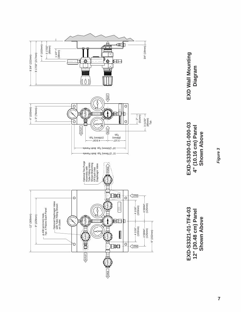
8
Connecting to a Cylinder: 1. Before removing the cylinder cap, move the gas cylinder to the work site: a. Secure cylinder to the floor, wall, or bench with appropriate chain, strap, or stand to prevent toppling. b. Remove the cylinder cap. c. Be sure the cylinder valve is tightly closed (clockwise) d. Remove the cylinder valve plug, if applicable/present. e. Inspect the cylinder valve and threads for damage or contamination.
2. Secure the cylinder connection to the cylinder in the following manner: a. Do not force. Tightening the nut onto the cylinder connection should be easy. If it is not, the connection may be wrong for the type of gas being used. b. Left-hand threads are used on some cylinder connections. A notch in the middle of the hex nut typically indicates a left-hand thread. c. Gaskets are used on some inlet connections. Be sure the gasket is in good repair condition. Do not over-tighten to avoid squashing the gasket into the gas line. Keep extra gaskets on hand. d. Never use oil or grease on regulator or cylinder fittings, as it may contaminate pure gases, or create a fire hazard.
Installing the outlet connection:The standard system has the outlet connection at the top of the EXD Pressure Differential Switchover system. Connect suitable tubing that is rated to the outlet pressure of the system to the connection.
Pressurizing the system for the first time:Before system startup, it is recommended that all systems be pressure tested, leak tested, and purged with an inert gas such as nitrogen. To accomplish this with connections other than CGA 580, it will be necessary to use an adapter. Use of an adapter is recommended only for temporary use, system start-up, and system checks. Adapters should never be used on a permanent basis.
1. Wear safety glasses and gloves.2. Be sure that both ends of all hoses and pigtails are secured before pressurizing. Turn the line regulator knob counterclockwise until the knob stops turning. 3. When first pressurizing, do not stand in front of in contact with the EXD Pressure Differential Switchover system. Slowly open the cylinder valve. Observe the high pressure gauge for a rise in pressure, up to full cylinder pressure. 4. Keep the hand wheel or wrench on the open cylinder valve at all times to allow prompt emergency shut-off.5. Inspect all connections for leaks and fix any leaks. If compatible with the application, a leak detection solution which indicates leaks by bubbling may be applied to the connection. To further check for leaks, or if the leak detection solution can not be used, close the cylinder valve for a period of time (recommended 24 hours), and observe the high pressure gauge for a drop in pressure. If indicated, recheck the CGA connection and all other high-pressure port connections. Never attempt to fix a leak under pressure. If leaks are detected, depressurize the system and retighten the connection. Begin again at step 3.
WARNING: While AURA assembles the EXD Pressure Differential Switchover system components to exacting leak-tight standards, the customer should also inspect for any loosening of internal parts that may occur in shipping or installation by completing the pressure decay test detailed above. Check for leaks on the system’s fittings as described above.
6. Slowly turn the line regulator knob clockwise. This will increase the pressure of the line. Adjust to the desired working pressure, and re-check for leaks using the methods described above.
Connecting to a High Pressure Cylinder
CAUTION
CAUTION

9
Operation1. At start up, connect full cylinders to the left and right inlets by following the section titled “Connecting a cylinder”.2. Rotate the priority valve such that the arrow points to the high-pressure cylinder you establish as primary. 3. Set the desired line pressure as required by the application. The EXD will automatically withdraw gas from the primary cylinder bank.4. The EXD 15 PSI, 50-PSI,100-PSI, and 150 PSI models will automatically switch over at 220 PSI and at 195 Psi. The 250 and 350 PSI models will switch at 485 PSI and 450 PSI.5. Bank depletion occurs when the inlet pressure gauge value has reached the respective switching pressure listed in step 4.6. Isolate the side that has depleted by closing it’s inlet isolation valve (if equipped) as illustrated in figure 4a.7. If both banks are high pressure cylinders, rotate the EXD Pressure Differential Switchover priority valve away from the depleted cylinder bank as illustrated in Figure 4b. 8. Replace the empty cylinders by following the section titled “Connecting High-Pressure Cylinders”.
MaintenanceAt regular intervals, the system should be checked for leaks and proper function (see "Troubleshooting"). Any leaks in the system should be corrected immediately. At no time should the priority valve regulator’s pressure settings be changed.
Isolation Valve
Bank PriorityIndicating Left
Figure 8B
Purge Valve
Gauge shows rightbank depletedleft bank full
Gauge shows
Isolation Valve
Bank PriorityIndicating Right
Figure 8A
Purge Valve
Gauge shows rightbank depletedleft bank full
Gauge shows
Figure 4a
Figure 4b
Illustrations shown with pigtail and cylinder installation for illustrative purposes.

10
ServiceIt is recommended that all servicing be done by a service facility authorized by AURA. Contact the AURA Customer Service Department for assistance. If so advised, the unit should be sent to a service facility authorized by AURA, adequately packaged in the original shipping container if possible, and shipped prepaid, with a statement of observed deficiency. The gas service used with the equipment must be clearly identified. All equipment must be purged before shipment to protect the transporter and service personnel. Purging is especially important if the equipment has been in hazardous or corrosive gas service. Return-trip transportation charges are to be paid by Buyer. In all cases, other than where warranty is applicable, repairs will be made at current list price for the replacement part(s), plus a reasonable labor charge. Test regulator for leaks on a routine schedule.
TroubleshootingTypical symptoms listed below indicate regulator malfunctions needing repair. Replace immediately with a clean, repaired, and tested regulator, or with a new system. 1. Gas leakage at the line regulator outlet when the adjusting knob of the line regulator is completely backed out.
2. With no flow through the system (downstream valves closed and adjusting knob in,) line pressure steadily increases above set pressure.3. Gas leakage from spring case (adjusting knob end of regulator).4. Gas leakage from any joint.5. Excessive drop in working pressure while regulator is flowing gas.6. Gas leakage from relief valve.7. Gas leakage from gauge.8. Gauge does not return to zero when not under gas pressure.9. Gauge does not consistently repeat the same reading.10. The system makes a noise or hums.
If the EXD Pressure Differential Switchover system seems to be using gas from the primary and reserve cylinders simultaneously (pressure is decreasing on both inlet gauges at the same time), do the following:
1. Make sure the priority valve knob is turned fully to the right or left.2. Observe the inlet pressure. It may be necessary to do this during the heaviest use of the system. If the inlet pressure is less than the values asssociated with the system, replace the high-pressure cylinders. If liquid cylinders are used and the inlet pressure increases significantly when the system is not in use, the system is over-withdrawing the liquid cylinders. Additional capacity may be added to the system to prevent this.3. If the above does not fix the problem, please contact AURA Customer Service. Please be prepared to give the following: • Model number • Gas service • Inlet pressure and type of gas supply (high pressure or liquid) • Outlet pressure • Approximate gas usage

11
Warranties are extended only with respect to the purchase of PRODUCTS directly from AURA, or its authorized DISTRIBUTOR, as new goods and are extended to the fi rst Buyer thereof other than for the purpose of resale.
For the life of the PRODUCTS to the fi rst Buyer, the PRODUCTS are warranted to be free from functional defects in materials and workmanship and to conform to the description of this equipment contained in its manual and any accompanying labels and/or inserts, provided that the same is properly operated under conditions of normal use and that regular periodic maintenance and service is performed or replacements made in accordance with the instructions provided. All electrical components in PRODUCTS are warranted to be free from functional defects in material and workmanship for only twelve (12) months from the date of purchase.
AURA’s sole and exclusive obligation and DISTRIBUTOR’s sole and exclusive remedy under the above warranties is limited to repairing or replacing, free of charge, at AURA’s option, the PRODUCTS, which are reported to DISTRIBUTOR from whom purchased, and which, if so advised, is returned with a statement of the observed defi ciency, to AURA or its designated service facility during normal business hours, transportation charges prepaid, and which, upon examination, is found not to comply with the above warranties. Return-trip transportation charges for the equipment shall be paid by DISTRIBUTOR.
There are no express or implied warranties which extend beyond the warranties hereinabove set forth. AURA makes no warranty of merchantability or fi tness for a particular purpose with respect to the goods or parts thereof.
This Warranty does not cover any damage to PRODUCTS that result from improper installation, accident, abuse, misuse, natural disaster, insuffi cient or excessive electrical supply, abnormal mechanical or environmental conditions, debris or particles in the gas or liquid source of supply, corrosion, or any unauthorized disassembly, repair, or modifi cation.
The foregoing warranties shall not apply if the PRODUCTS have been 1) repaired other than by AURA or its designated service facility, 2) not in accordance with written instructions provided by AURA, or 3) altered by anyone other than AURA.
AURA SHALL NOT BE OTHERWISE LIABLE FOR ANY DAMAGES INCLUDING BUT NOT LIMITED TO, INCIDENTAL DAMAGES, CONSEQUENTIAL DAMAGES, OR SPECIAL DAMAGES, WHETHER SUCH DAMAGES RESULT FROM NEGLIGENCE, BREACH OF WARRANTY, OR OTHERWISE.

AURA Precision Gas Controls1501 Harpers Road • Virginia Beach, VA 23454
1.800.582.2565 • www.auracontrols.com
IMD0611B 6.2012
Certifi ed ISO 9001