Embed Size (px)
Citation preview

4 Design and Technology of Excimer Lasers
H. von Bergmann, U. Rebhan, U. Stamm
Although the chemical reaction processes responsible for the excitation ofexcimer lasers seem to offer ideal operational conditions, the technical real-ization of reliable laser systems for scientific and industrial use is a demandingtask. The design of excimer lasers is complicated by several factors. The gasmixtures used in the laser contain the halogens fluorine or chlorine, whichare highly corrosive. The laser systems are operated at gas pressures of upto 6 × 10⁵ Pa and can contain relatively large gas volumes, making high-strength mechanical construction necessary. Voltages of more than 40 kV areused for the excitation, requiring efficient high-dielectric-strength insulators.These factors severely limit the choice of materials that can be employedfor the construction of the laser. The design of lasers to be employed in theindustrial environment is more demanding than that for scientific and lab-oratory use. In contrast to scientific applications, where performance is themost important question, in industry issues such as low operating cost, long-term reliability, ease of operation and safety are of overriding importance.As a consequence, designs prefer simple and proven technology, being cau-tious of possibly more efficient, but more complex and therefore higher riskapproaches.
4.1 Excitation
The design of the laser system mainly depends on the method of excita-tion, which can be performed either by electron beam, microwaves or gasdischarge. In the first case, the excitation energy is transmitted by a pulsedelectron beam, which laterally penetrates the gas-filled laser tube througha thin foil. While electron-beam-excited systems have the advantage of veryhigh pulse energies, up to several kJ , and large beam cross sections, theyemploy complex and inefficient high voltage technology and are intrinsicallylimited to repetition rates of only a few Hz. For industrial applications thislaser design is not appropriate because of high operational costs as well asshort tube lifetimes. Microwave excitation can be realized by applying a mi-crowave signal to electrodes attached to a laser-gas-filled capillary tube. Even
48 4 Design and Technology of Excimer Lasers
though experimental designs have reached pulse frequencies of up to 8 kHz,the microwave excitation method is of no industrial relevance due to the lowachievable energy per pulse of about 100µJ [1] and associated average pow-ers of fractions of a watt. The technology, almost exclusively employed byreliable, high-power industrial excimer lasers, is high-pressure gas dischargeexcitation, which can provide outputs of up to several joule and repetitionrates in the kHz range. Figure 4.1 shows the gas discharge section of a typicaltransversely excited excimer laser tube schematically.
Fig. 4.1. Schematic diagram of excimer laser
The discharge unit is integrated into the laser tube, which is designed asa high-pressure gas vessel. The laser gas mixture consists of a 0.05% to 0.5%halogen component for halogen excimer lasers, 3% to 10% inert gas compo-nent, and the buffer gas (helium or neon) at a pressure of 1.5 × 10⁵ Pa to6 × 105 Pa. This high pressure makes a continuous gas discharge virtuallyimpossible. After some ten nanoseconds streamers start to develop and theinitial glow discharge degrades into an arc or spark discharge, which is notsuitable for the excitation process and will damage the electrodes. Therefore,most industrial excimer lasers utilize short excitation pulses, which termi-nates the discharge prior to the onset of streamer and arc formation. Thisleads to the typical short laser pulses of 10 ns to 30 ns. The technique toproduce and control a homogeneous gas discharge is crucial for the perfor-mance of an excimer laser. The most critical parts of this technique are thepreionization of the laser gas, the discharge electrodes, the gas flow system,and the high-power discharge circuit.
4.2 Preionization 49
4.2 Preionization
Preionization means the seeding of the discharge volume uniformly with elec-trons prior to the initiation of the main discharge. It is necessary in order toprepare a uniform glow discharge and avoid arcing. Parameters that affect thepreionization, such as threshold value, seed electron density and uniformity,are heavily dependent on the design of the discharge system such as typeof electrode and profile, gas pressure, duration of preionization, electron lossprocesses, time delay between preionization and main discharge, rise timeof electrode voltage, as well as on the overall discharge system geometry.Electron densities of 107 to 109 cm−3 are required to produce a uniform arc-free discharge. However, even if an arc-free discharge is obtained the outputenergy and the discharge stability are improved with increased electron den-sities. At low preionization densities the discharge consists of a large numberof filaments, which lead to increased electrode erosion, and unsatisfactory uti-lization of the gas medium. Also the timing of the preionization with respectto the main discharge and the spatial uniformity are of extreme importance.
There are several electrode structures and preionization techniques thatcan be employed for the excitation of the laser. These determine the dischargecross-section and quality and with it the laser energy output and efficiency,which in turn have a strong impact on the design of the laser and powerconditioning system. The electrode systems commonly used for the excitationof high-repetition-rate excimer lasers fall into two categories: solid electrodeswith side preionization, spark arrays or corona bars, and combinations of solidand screen electrodes with the preionization source located behind the screen.Preionization relies on photo ionisation of background trace impurities M ofthe gas and proceeds according to the following reaction:
hν + M ⇒ M+ + e− with hν ≥ 12 eV (4.1)
Preionization can either be effected by UV radiation [2] or by X-rays.X-rays allow to preionize large discharge cross-sections and to achieve pulseenergies of up to several joule, but they considerably increase system cost andcomplexity. In addition, the high X-ray fluxes required at high repetition ratesnecessitate elaborate X-ray shielding and are therefore generally not desirablein systems for industrial use. Finally suitable X-ray sources have not yetdemonstrated reliable long-life operation at high repetition rates. Industrialexcimer lasers therefore generally rely on UV preionization by either sparkdischarges or surface corona discharges. Schematic arrangements used for UVpreionization are shown in Fig. 4.2.
The typical set-ups employed for spark preionization are shown in Figs.4.2a and 4.2b. Preionization pins arranged in a row adjacent to the dischargeelectrodes or behind a screen electrode generate a spark discharge some 10 nsbefore the main discharge. The UV radiation produced by the sparks is suf-ficient to preionize the laser gas between the electrodes with a homogeneous
50 4 Design and Technology of Excimer Lasers
initial seed density of at least 108 electrons/cm3. While sparks provide highelectron densities, the uniformity tends to be relatively poor and spark elec-trode burn-off causes system pollution, which limits gas and electrode life.In recent industrial excimer laser designs the spark preionization could besignificantly improved by placing a dielectric material like alumina betweenthe preionization pins as shown in Fig. 4.2c [3]. The resulting surface-guideddischarge spreads over several millimeters instead of forming a very thin dis-charge channel and the erosion rate of the preionization pins is reduced byan order of magnitude or more. This design enables longer gas lifetime andelectrode life of 10 billion pulses. Most of the high-average-power industrialexcimer lasers benefit from this preionization design.
For high-repetition-rate lasers the surface corona preionization (SCP) hasbeen introduced (see Fig. 4.2d) [4]. SCP proved to be superior to conventionalpreionization sources at kHz repetition rate because of the ability to generatesufficient electron density levels for a narrow high-repetition-rate dischargevolume using a significantly lower amount of energy and with a much higherspatial uniformity. This results in improved output stability and increaseddischarge electrode life.
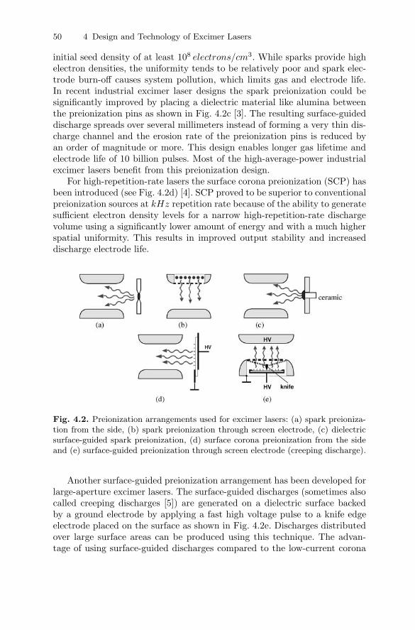
Fig. 4.2. Preionization arrangements used for excimer lasers: (a) spark preioniza-tion from the side, (b) spark preionization through screen electrode, (c) dielectricsurface-guided spark preionization, (d) surface corona preionization from the sideand (e) surface-guided preionization through screen electrode (creeping discharge).
Another surface-guided preionization arrangement has been developed forlarge-aperture excimer lasers. The surface-guided discharges (sometimes alsocalled creeping discharges [5]) are generated on a dielectric surface backedby a ground electrode by applying a fast high voltage pulse to a knife edgeelectrode placed on the surface as shown in Fig. 4.2e. Discharges distributedover large surface areas can be produced using this technique. The advan-tage of using surface-guided discharges compared to the low-current corona

4.3 Discharge Electrodes 51
discharge SCP of Fig. 4.2d is the possibility to relatively easily optimize theintensity of the preionization.
4.3 Discharge Electrodes
Electrode systems employed in excimer lasers are either screen electrodeswith behind-the-screen preionization or solid discharge electrodes using sidepreionization. Screen electrodes can provide superior homogeneity of preion-ization, especially in large cross section systems, but are intrinsically fragileand can easily be destroyed by discharge arcing at high repetition rates. Soliddischarge electrodes utilizing side preionization are therefore commonly usedfor the excitation of high power and of high-repetition-rate industrial excimerlasers.
In high-pressure gas discharge lasers the discharge electrodes have to becarefully profiled in order to provide a highly uniform electric field distri-bution in the discharge region and to avoid field concentrations near theelectrode edges. A field uniformity of the order of ∆E/E ≤ 10−3 is generallyrequired to avoid premature discharge instabilities and arcing. This require-ment results in mechanical tolerances of the electrode of better than 50µm.The electrode profile does not only determine the maximum arc-free energyloading of the discharge but also the discharge width and profile, which inturn controls the profile of the laser beam. Uniform field electrode profiles canbe derived empirically, calculated analytically [6, 7] or by numerical meth-ods [8], and are manufactured to the required tolerance of a few µm usingnumerically controlled milling machines. Design criteria include field unifor-mity, edge-enhancement of field, compactness of the electrode (i.e. ratio ofdischarge and electrode width) and generated discharge profile. While an-alytical techniques provide useful results, they do not include second ordereffects such as field distortions caused by nearby current returns and insulat-ing structures. Numerical techniques are therefore superior for the electrodedesign [8].
Material and surface finish of the electrode have a strong influence onthe discharge characteristics and electrode service life. The electrodes haveto withstand the erosion caused by the high-current discharge and have tobe chemically resistant to the fluorine or chlorine component used in the gasmixture. Materials employed include stainless steel, pure nickel, aluminumnickel alloys and brass as well as combinations such as nickel-plating on acopper or aluminum base.
Commercial excimer lasers running with fluorine as halogen componentare normally equipped with brass electrodes, which proved to be superiorabove all other electrode materials. The benefits of brass electrodes are along lifetime and a lower window contamination rate compared to nickel orstainless steel electrodes. Intensive material studies have been done to deter-mine the optimum brass alloy for cathode and anode. A lead content of 3 to
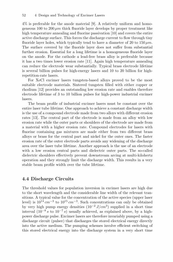
52 4 Design and Technology of Excimer Lasers
4% is preferable for the anode material [9]. A relatively uniform and homo-geneous 100 to 200 µm thick fluoride layer develops by proper treatment likehigh temperature annealing and fluorine passivation [10] and covers the entireactive discharge surface. This forces the discharge current to flow through tinyfluoride layer holes, which typically tend to have a diameter of 20 to 150µm.The surface covered by the fluoride layer does not suffer from substantialfurther erosion. Essential for a long lifetime is a homogeneous fluoride layeron the anode. For the cathode a lead-free brass alloy is preferable becauseit has a two times lower erosion rate [11]. Again high temperature annealingcan reduce the electrode wear substantially. Typical brass electrode lifetimeis several billion pulses for high-energy lasers and 10 to 20 billion for high-repetition-rate lasers.
For XeCl excimer lasers tungsten-based alloys proved to be the mostsuitable electrode materials. Sintered tungsten filled with either copper orrhodium [12] provides an outstanding low erosion rate and enables thereforeelectrode lifetime of 3 to 10 billion pulses for high-power industrial excimerlasers.
The beam profile of industrial excimer lasers must be constant over theentire laser tube lifetime. One approach to achieve a constant discharge widthis the use of a compound electrode made from two alloys with different erosionrates [13]. The central part of the electrode is made from an alloy with lowerosion rate while the outer parts or shoulders of the electrode are made froma material with a higher erosion rate. Compound electrodes for lasers withfluorine containing gas mixtures are made either from two different brassalloys or brass for the central part and nickel for the outer ones. The fastererosion rate of the outer electrode parts avoids any widening of the dischargearea over the laser tube lifetime. Another approach is the use of an electrodewith a low erosion central parts and dielectric outer parts. The so-calleddielectric shoulders effectively prevent downstream arcing at multi-kilohertzoperation and they strongly limit the discharge width. This results in a verystable beam profile width over the tube lifetime.
4.4 Discharge Circuits
The threshold values for population inversion in excimer lasers are high dueto the short wavelength and the considerable line width of the relevant tran-sitions. A typical value for the concentration of the active species (upper laserlevel) is 1014 cm−3 to 1015 cm−3. Such concentrations can only be obtainedby very high pump energy densities (10−2 J/cm3) supplied in a short timeinterval (10−8 s to 10−7 s) usually achieved, as explained above, by a high-power discharge pulse. Excimer lasers are therefore invariably pumped using adischarge circuit (pulser) that discharges the stored electrical energy directlyinto the active medium. The pumping schemes involve efficient switching ofthis stored electrical energy into the discharge system in a very short time

4.4 Discharge Circuits 53
and with a well defined spatial and temporal profile as this determines thedischarge uniformity and – in turn – influences the spatial uniformity of theextracted laser beam. These requirements impose severe requirements on thepumping scheme in terms of peak currents and voltage rise times. Besidesthe charging section, the pumping scheme of excimer lasers usually consistsof a network of inductors and capacitors (discharge circuit), which is designedto closely match the dynamic behavior of the gas discharge, where the re-sistance is rapidly changing with time. The discharge circuit conventionallyused for the excitation of medium-power excimer lasers is the basic capacitortransfer (C-C transfer) circuit as shown in Fig. 4.3. The C-C transfer circuitemploys simple matched energy transfer from a storage capacitor C1, whichis initially charged to the required high voltage, to the discharge peaking ca-pacitor C2. Once the voltage on C2 and with it the electrode voltage rises tothe level necessary for discharge initiation the energy is then switched intothe discharge. The loop inductance L2 consists of the stray inductance of theelectrode system and can be kept at a few nH, resulting in a fast currentpulse and extreme power deposition levels.
Fig. 4.3. Excimer laser discharge circuit with thyratron switch
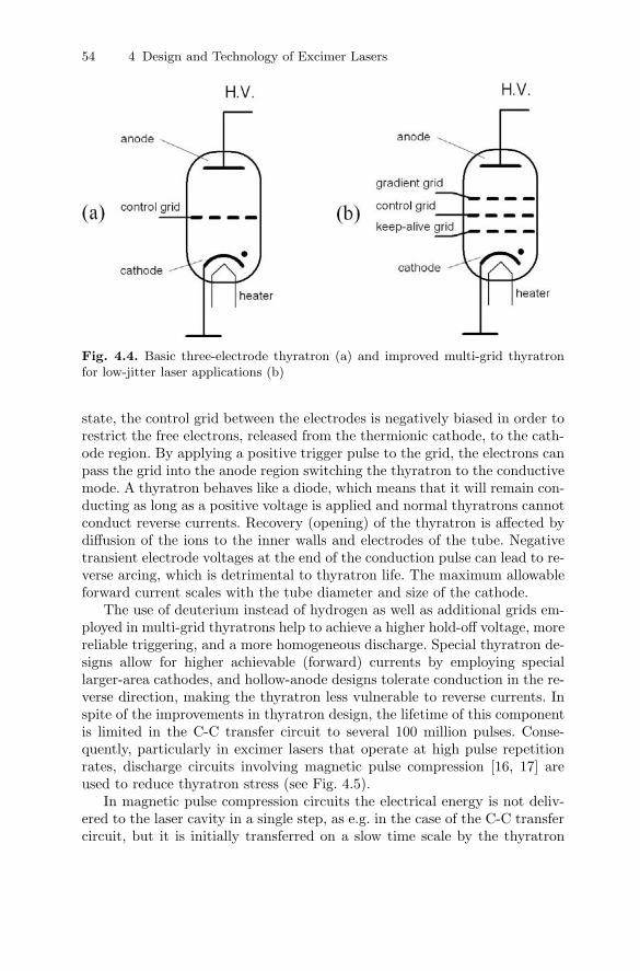
The limiting component in this type of circuit is the high-voltage switch-ing element, which has to withstand the high voltage and current duringthe discharge cycle (peak voltage up to 40 kV , peak current at about 10 to100 kA, current rise times of 30 to 100ns) [14, 15]. In the first excimer lasers,spark gaps were used as high-voltage switches. These were quickly replacedby thyratrons due to their better reliability and lifetime characteristics. Thedesign of a basic three-electrode thyratron and an improved multi-grid thyra-tron for laser applications are shown in Fig. 4.4.
A thyratron tube is filled with hydrogen at a low gas pressure, providedby heating of an internal hydrogen-metal reservoir (palladium). Thyratronsoperate on the left side (vacuum side) of the Paschen curve and the hydrogenpressure determines the hold-off voltage of the tube. In the non-conductive
54 4 Design and Technology of Excimer Lasers
Fig. 4.4. Basic three-electrode thyratron (a) and improved multi-grid thyratronfor low-jitter laser applications (b)
state, the control grid between the electrodes is negatively biased in order torestrict the free electrons, released from the thermionic cathode, to the cath-ode region. By applying a positive trigger pulse to the grid, the electrons canpass the grid into the anode region switching the thyratron to the conductivemode. A thyratron behaves like a diode, which means that it will remain con-ducting as long as a positive voltage is applied and normal thyratrons cannotconduct reverse currents. Recovery (opening) of the thyratron is affected bydiffusion of the ions to the inner walls and electrodes of the tube. Negativetransient electrode voltages at the end of the conduction pulse can lead to re-verse arcing, which is detrimental to thyratron life. The maximum allowableforward current scales with the tube diameter and size of the cathode.
The use of deuterium instead of hydrogen as well as additional grids em-ployed in multi-grid thyratrons help to achieve a higher hold-off voltage, morereliable triggering, and a more homogeneous discharge. Special thyratron de-signs allow for higher achievable (forward) currents by employing speciallarger-area cathodes, and hollow-anode designs tolerate conduction in the re-verse direction, making the thyratron less vulnerable to reverse currents. Inspite of the improvements in thyratron design, the lifetime of this componentis limited in the C-C transfer circuit to several 100 million pulses. Conse-quently, particularly in excimer lasers that operate at high pulse repetitionrates, discharge circuits involving magnetic pulse compression [16, 17] areused to reduce thyratron stress (see Fig. 4.5).
In magnetic pulse compression circuits the electrical energy is not deliv-ered to the laser cavity in a single step, as e.g. in the case of the C-C transfercircuit, but it is initially transferred on a slow time scale by the thyratron

4.4 Discharge Circuits 55
Fig. 4.5. Single stage magnetic switch circuit
from the primary energy store C1 to an intermediate energy store C2, fromwhere it is then transferred rapidly to C3 and the laser cavity by the magneticswitch (LMS). Because of the slow initial transfer rate, peak currents carriedby the thyratron can be reduced, allowing it to operate well below its risetime and peak current limits and thereby leading to extended thyratron lifeof up to 2 billion pulses.
The magnetic switch is realised by a saturable inductor employing ferriteor amorphous metal as core material. The non-saturated, high inductanceof the inductor does not permit significant current flow and does thereforeconstitute the open position of the switch. Switch closure is affected by driv-ing the inductor into saturation, which reduces the inductance to close theequivalent air core value. Total energy transfer between successive loops isachieved if the energy transfer time from C1 to C2 is matched to the timerequired for inductor LMS to be driven into saturation (hold-off time). Thepulse compression ratio δ between the loops is defined as
δ =t1t2
=√
L1/LsatMS (4.2)
where t1 and t2 are the transfer times of loops 1 and 2, respectively, andL
satMS is the saturated inductance of LMS . Typically achieved compression
ratios for a single stage range from 2 to 5 and several stages can be cascadedto achieve overall pulse compression ratios of several orders of magnitude[18]. Since saturable inductors are passive switching elements they can bedesigned for very high peak currents and hold-off voltages and have a virtuallyunlimited lifetime.
Various types of excitation circuits employing magnetic pulse compressionhave been used. Figure 4.6a shows a L-C inversion circuit employing a singlestage of pulse compression [18]. The L-C inversion circuit has the advantageof voltage doubling and therefore halves the operating voltage for the switch.

56 4 Design and Technology of Excimer Lasers
Fig. 4.6. Excitation circuits employing magnetic pulse compression: (a) L-C inver-sion circuit with single-stage pulse compression and (b) thyristor-switched circuitusing double-stage pulse compression.
The associated disadvantage of increased switching currents at the lower volt-age can be removed by the addition of one or more pulse compression stages.
Thyratrons can be eliminated entirely by the use of multi-stage pulse com-pression techniques and all-solid-state switching by modern semiconductorswitches such as thyristors, GTOs (gate turn-off) or IGBTs (insulated gatebipolar transistor) [14]. Solid-state switches have important advantages com-pared to thyratrons, which include longer service lifetime, low cost and bet-ter availability. Solid-state switches are limited to comparatively low voltagesand long switching times and they are in general sensitive to over-voltagesand over-currents. Special excitation circuits including voltage step-up tech-niques such as pulse transformers as well as multi-stage magnetic pulse com-pression and protection against voltage and current surges have thereforeto be employed. The thyristor-switched compressor shown schematically inFig. 4.6b employs a pulse step-up transformer and two stages of magneticpulse compression to bring the pulse voltage and switching times into theregime of commercially available thyristors. All-solid-state switching tech-nology constitutes a major advancement towards highly reliable industrialexcimer laser systems, since solid-state switches are maintenance free andhave demonstrated a practically unlimited lifetime. Today all high-power in-dustrial excimer lasers and high-repetition-rate lasers for microlithographyapplications are utilizing solid-state switching technology and achieve main-tenance free operating times of several 1000 hours on routine base. Even lowenergy medical excimer laser systems benefit from solid-state switching be-

4.4 Discharge Circuits 57
cause the solid-state switch does not require any warm-up time and makeslaser radiation immediately available.
The all-solid-state switching technology allows recovering the energy,which is reflected by the discharge due to impedance mismatch. Either diodesor active circuits can achieve this. In both cases the reflected energy is flowingback to the main storage capacitor instead of ringing through the stages ofthe excitation circuit and returning to the laser electrodes after several 100nsto some microseconds. This late pulse creates a poor discharge and resultsin excessive electrode wear. Therefore all solid-state switching technology al-lows to extend the electrode life, reduces the halogen consumption and thecontamination generation.
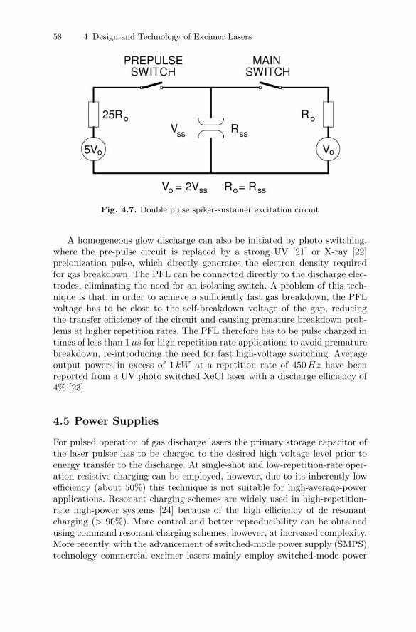
The electrical switching technology as described above, although reliableand effective at high repetition rates, suffers from one principle problem.The fast high voltage pulse, required for the formation of a homogeneousdischarge, is not consistent with the efficient impedance matching of pulserand discharge. For single pulse discharge circuits the pulser-to-plasma en-ergy transfer efficiency is therefore limited to 40 to 60%, resulting in overallwall plug efficiencies for the laser of 1 to 3%. Higher efficiencies can only beachieved by double pulse excitation circuits (spiker-sustainer circuits) [15] asshown schematically in Fig. 4.7, where the functions of gas breakdown anddischarge formation are separated from the process of energy feeding dur-ing the quasi steady state of the discharge. A fast, low-energy, high-voltagepre-pulse circuit is employed for discharge initiation and a separate low-impedance pulse forming line (PFL) as a sustainer. The impedance-matchedPFL is charged at a slow rate to the matched voltage of twice the self sus-tained plasma voltage, and can achieve transfer efficiencies approaching 100%.Magnetic switches are generally employed for the main switch, to isolate thePFL during discharge initiation. In addition to generating higher efficiencies,this technique also allows for the extraction of long optical pulses. Efficien-cies and pulse durations that have been produced with this technique areabout 5% [19] and 1.5 µs [20] respectively for low-repetition-rate XeCl lasers.An additional benefit of this technique is the lowering of the demands forthe high-voltage switch, since only the low-energy spiker circuit has to beswitched at a fast rate, while the PFL can be charged at a slow rate, com-patible with thyristor switching. An example of such a system is shown inSection 5.1. Although the double pulse excitation circuit has some inherentadvantage it is not used in commercial excimer lasers because of the addedcomplexity of the electrical circuit and the reduced pulse energy stabilityachieved at high repetition rate operation.
58 4 Design and Technology of Excimer Lasers
Fig. 4.7. Double pulse spiker-sustainer excitation circuit
A homogeneous glow discharge can also be initiated by photo switching,where the pre-pulse circuit is replaced by a strong UV [21] or X-ray [22]preionization pulse, which directly generates the electron density requiredfor gas breakdown. The PFL can be connected directly to the discharge elec-trodes, eliminating the need for an isolating switch. A problem of this tech-nique is that, in order to achieve a sufficiently fast gas breakdown, the PFLvoltage has to be close to the self-breakdown voltage of the gap, reducingthe transfer efficiency of the circuit and causing premature breakdown prob-lems at higher repetition rates. The PFL therefore has to be pulse charged intimes of less than 1 µs for high repetition rate applications to avoid prematurebreakdown, re-introducing the need for fast high-voltage switching. Averageoutput powers in excess of 1 kW at a repetition rate of 450Hz have beenreported from a UV photo switched XeCl laser with a discharge efficiency of4% [23].
4.5 Power Supplies
For pulsed operation of gas discharge lasers the primary storage capacitor ofthe laser pulser has to be charged to the desired high voltage level prior toenergy transfer to the discharge. At single-shot and low-repetition-rate oper-ation resistive charging can be employed, however, due to its inherently lowefficiency (about 50%) this technique is not suitable for high-average-powerapplications. Resonant charging schemes are widely used in high-repetition-rate high-power systems [24] because of the high efficiency of dc resonantcharging (> 90%). More control and better reproducibility can be obtainedusing command resonant charging schemes, however, at increased complexity.More recently, with the advancement of switched-mode power supply (SMPS)technology commercial excimer lasers mainly employ switched-mode power
4.5 Power Supplies 59
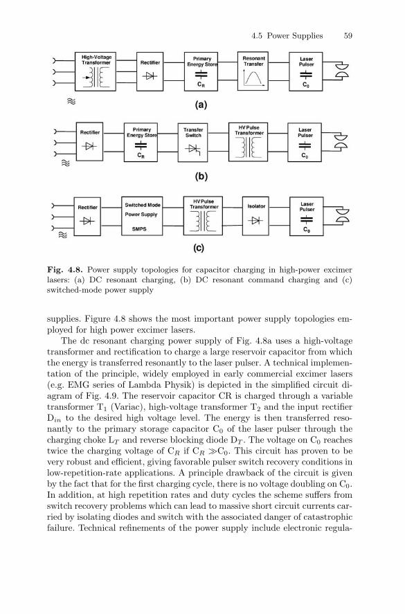
Fig. 4.8. Power supply topologies for capacitor charging in high-power excimerlasers: (a) DC resonant charging, (b) DC resonant command charging and (c)switched-mode power supply
supplies. Figure 4.8 shows the most important power supply topologies em-ployed for high power excimer lasers.
The dc resonant charging power supply of Fig. 4.8a uses a high-voltagetransformer and rectification to charge a large reservoir capacitor from whichthe energy is transferred resonantly to the laser pulser. A technical implemen-tation of the principle, widely employed in early commercial excimer lasers(e.g. EMG series of Lambda Physik) is depicted in the simplified circuit di-agram of Fig. 4.9. The reservoir capacitor CR is charged through a variabletransformer T1 (Variac), high-voltage transformer T2 and the input rectifierDin to the desired high voltage level. The energy is then transferred reso-nantly to the primary storage capacitor C0 of the laser pulser through thecharging choke LT and reverse blocking diode DT . The voltage on C0 reachestwice the charging voltage of CR if CR �C0. This circuit has proven to bevery robust and efficient, giving favorable pulser switch recovery conditions inlow-repetition-rate applications. A principle drawback of the circuit is givenby the fact that for the first charging cycle, there is no voltage doubling on C0.In addition, at high repetition rates and duty cycles the scheme suffers fromswitch recovery problems which can lead to massive short circuit currents car-ried by isolating diodes and switch with the associated danger of catastrophicfailure. Technical refinements of the power supply include electronic regula-

60 4 Design and Technology of Excimer Lasers
Fig. 4.9. DC resonant power supply
tion of the charging voltage, replacing mechanical Variac control, and theaddition of an auxiliary power supply to circumvent the “first shot” problem.
Command resonant charging power supplies (Fig. 4.8b) utilize an ad-ditional switch, which isolates the power supply from the laser switch un-til it has fully recovered after the discharge. The reservoir capacitor CR
is charged directly from the rectified mains voltage and the laser pulser ischarged through a high-voltage pulse transformer to the required voltage.The resonant regulating pulsed power supply (R2P2) of Fig. 4.10 employsswitch S2 to resonantly charge the intermediate storage capacitor C0 to thedesired voltage [25]. Diode D1 serves to bypass the transformer primary dur-ing the charging of C0. Accurate voltage regulation on C0 is achieved by theregulating thyristor S1, which serves to divert the transfer charging current,once triggered, thereby effectively stopping energy transfer to C0. Matchedenergy transfer between C0 and the primary storage capacitor of the laserpulser C1 through high voltage pulse transformer T1 is initiated by switchingthyristor S3. Average power levels of up to 50 kW have been demonstratedusing multiple time-multiplexed R2P2 power supply modules [26].
Fig. 4.10. Resonant regulating pulsed power supply (R2P2)
4.5 Power Supplies 61
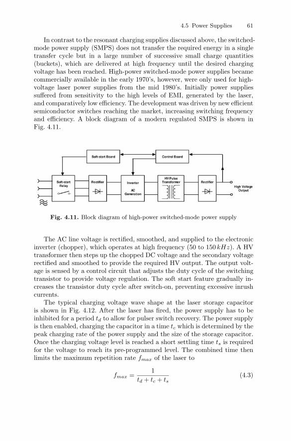
In contrast to the resonant charging supplies discussed above, the switched-mode power supply (SMPS) does not transfer the required energy in a singletransfer cycle but in a large number of successive small charge quantities(buckets), which are delivered at high frequency until the desired chargingvoltage has been reached. High-power switched-mode power supplies becamecommercially available in the early 1970’s, however, were only used for high-voltage laser power supplies from the mid 1980’s. Initially power suppliessuffered from sensitivity to the high levels of EMI, generated by the laser,and comparatively low efficiency. The development was driven by new efficientsemiconductor switches reaching the market, increasing switching frequencyand efficiency. A block diagram of a modern regulated SMPS is shown inFig. 4.11.
Fig. 4.11. Block diagram of high-power switched-mode power supply
The AC line voltage is rectified, smoothed, and supplied to the electronicinverter (chopper), which operates at high frequency (50 to 150 kHz). A HVtransformer then steps up the chopped DC voltage and the secondary voltagerectified and smoothed to provide the required HV output. The output volt-age is sensed by a control circuit that adjusts the duty cycle of the switchingtransistor to provide voltage regulation. The soft start feature gradually in-creases the transistor duty cycle after switch-on, preventing excessive inrushcurrents.
The typical charging voltage wave shape at the laser storage capacitoris shown in Fig. 4.12. After the laser has fired, the power supply has to beinhibited for a period td to allow for pulser switch recovery. The power supplyis then enabled, charging the capacitor in a time tc which is determined by thepeak charging rate of the power supply and the size of the storage capacitor.Once the charging voltage level is reached a short settling time ts is requiredfor the voltage to reach its pre-programmed level. The combined time thenlimits the maximum repetition rate fmax of the laser to
fmax =1
td + tc + ts(4.3)

62 4 Design and Technology of Excimer Lasers
Fig. 4.12. Switched-mode power supply charging of laser storage capacitor
A principle problem of switched-mode power supplies is that the loadcapacitor is charged by a succession of small voltage steps caused by the fi-nite size of individual charge buckets (see enlarged view in Fig. 4.12). Theresulting size of the individual voltage steps determines the accuracy of volt-age regulation achievable from the power supply. The step size ∆V can becalculated from [27]:
∆V = Iout/ (CL × fPS) (4.4)
where Iout is the rated charging current of the power supply, CL the loadcapacitor and fPS the switching frequency of the power supply. In order toincrease voltage regulation accuracy for a given load it is clearly desirableto run the SMPS at high switching frequencies. Modern SMPS operate withswitching frequencies of about 40 kHz resulting in a typical voltage accuracyof 1%. For certain applications of excimer lasers, such as photolithography,this voltage accuracy and repeatability is not sufficient. Voltage repeatabilityas low as 0.05% can be achieved using advanced frequency and phase shiftingtechniques [28]. Capacitor charging power supplies are today commerciallyavailable that provide peak charging rates of up to 37 kJ/s and average DCpowers of up to 50 kW with overall efficiencies of better than 85%.
4.6 Circulation, Laser Gas Cooling, and Cleaning
In excimer lasers, operating at typically 2% conversion efficiency betweenelectrical input power and optical output power, the surplus energy has tobe removed efficiently as excess heat. Usually the active medium is containedin an aluminum or stainless steel pressure vessel of sufficient volume. Aninternal fan causes a forced circulation of the laser gas in order to keep the

4.6 Circulation, Laser Gas Cooling, and Cleaning 63
active medium well mixed and renewed in the lasing region and to obtain ahigh flow rate through the gas filter and the heat exchanger. Gas circulationis achieved by cross flow fans that provide a homogeneous gas flow rate overthe entire electrode length. Typical gas circulation speed is about 25 m/sfor high energy and about 50m/s for high-repetition-rate industrial excimerlasers.
As with all gas laser cooling systems, the efficient heat transfer betweenthe laser gas and the heat exchanger is a challenge. The heat exchanger, whichin most designs uses water as cooling medium in a closed or open loop system,needs a sufficient contact area to allow good temperature stability, especiallyat high pulse repetition rates. On the other hand the gas flow pressure dropacross the heat exchanger must be small in order to be compatible with thecross flow fan characteristic. Nickel-plated copper heat exchanger tubes withsmall to medium-sized fins are today standard in excimer lasers. A schematicsketch of an excimer laser tube cross section is shown in Fig. 4.13.
Fig. 4.13. Cross-section of an excimer laser gas flow system
The laser tube windows are very sensitive to all kinds of contamination.The outside of a tube window is frequently purged by dry pure nitrogento remove all gaseous contaminations and impurities present in the environ-mental air. Sophisticated purge systems are today standard on all high-powerand high-repetition-rate excimer lasers, even at 308 nm. Active and passivecontamination control is necessary to keep the inside of the tube windowsclean. A window service time of up to 10 billion pulses can be achieved with
64 4 Design and Technology of Excimer Lasers
an optimized contamination control system and is a precondition for longuninterrupted operating times of excimer lasers.
Passive contamination control starts with the selection of a low-erosion-rate electrode material and suitable materials for the pressure vessel andits internal components. All parts of the pressure vessel must be carefullycleaned because even traces of grease, oil and other lubricant in the ppmrange strongly affect the laser performance. Wet chemical cleaning followed byplasma cleaning and clean room assembly are today the standard procedure.A highly sophisticated passivation procedure is applied to build up a halidelayer on all internal parts of the laser tube and avoid any contaminationbuild-up by reaction of the halogen component of the gas mixture with thepressure vessel.
Active contamination control is achieved by electrostatic dust filtrationand in some cases by cryogenic gas purification. The electrode burn-off – un-avoidable even with the best electrode material – causes solid and gaseousimpurities. Electrostatic dust precipitators can remove most of the solid re-action products. A fraction of the main gas flow is directed through the dustprecipitator device. The pressure difference between intake and exit port ofthe precipitator drives the gas through the device without any additionalactive fan or gas pump. Corona wires are used to charge dust particles of theincoming dust-loaded laser gas. The gas flow speed within the precipitator isnormally reduced to below 1m/s to allow settling of the charged dust parti-cles on the grounded precipitator walls. The cleaned dust-free gas is returnedto the laser tube near the windows via so-called baffle boxes, which preventshock waves from transporting dust up to the windows. A window lifetime of10 billion pulses and more is today standard in high repetition rate industrialexcimer lasers with a well-designed dust precipitation system.
The unavoidable halogen gas loss due to the electrode erosion is com-pensated by halogen injections. Sophisticated self-learning replenishment al-gorithms add very small portions of halogen gas to the laser gas mixturewithout affecting energy stability of the laser during the injection phase. Thereplenishment rate depends on laser operating time, laser input energy andlaser performance parameters like high voltage level or temporal pulse width.The algorithms allow keeping the high voltage level and therefore all essentialbeam parameters stable over up to one billion pulses with a single gas fill.
4.7 Safety Standards for Industrial Excimer Lasers
Today industrial laser systems have to fulfill the requirements of numerousstandards and regulations like other machinery. Among these regulations isthe European CE (Conformite Europeenne) mark, which appears on prod-ucts that meet safety standards that apply to all countries of the EuropeanUnion (EU). The CE mark was introduced to facilitate the free movement ofgoods within the European Union.
4.7 Safety Standards for Industrial Excimer Lasers 65
The compliance with laser radiation safety standards is also mandatory forindustrial excimer laser equipment. Additionally, users in the semiconductorindustry frequently ask for compliance of laser equipment with the applicablestandards of SEMI organization.
4.7.1 CE Mark
Industrial excimer laser systems have to carry the European CE mark andmust comply with four applicable European directives:
– Electromagnetic Compatibility (EMC) Directive 89/366/ECC– Low Voltage Directive 73/23/ECC– Pressure Equipment Directive 97/23/EC– Machinery Directive 89/392/EEC (Amended 98/37/EEC)
89/366/ECC
The EMC directive came into force on 1st January 1992, and replaced allexisting legislation for electrical and electronic equipment concerned from 1st
January 1996. EMC stands for Electromagnetic Compatibility and describesthe way an electric or electronic apparatus behaves (regarding EM aspects)in the presence of other equipment. This discipline investigates the unwantedemissions and unwanted susceptibility of electronics against electromagneticfields and a number of associated phenomena, known to interfere with elec-tronics in a similar way. The technical goal of this directive is two-way:
– Protect the radio spectrum against interfering equipment– Protect equipment from common interference
In essence the requirements of the directive are very simple – it basicallystates that a laser system must not emit unwanted electromagnetic pollution(interference). Because there is a certain amount of electromagnetic pollutionin the environment, the directive also states that a laser system must beimmune to a reasonable amount of interference. The directive itself gives nofigures or guidelines on what the required levels of emissions or immunityare, nor does it state the frequency band limits. This interpretation of thedirective’s requirements is left to the standards that are used to demonstratecompliance with the directive.
All EMC standards are today summarized in the European standardseries EN61000. This series include four generic standards for EMC. Twogeneric standards are specifying the levels for residential, commercial andlight-industrial environments; the other two generic standards set the levelsfor industrial environments. An environment is regarded as industrial if aseparate mains substation supplies it.
4.7.2 Electromagnetic Compatibility (EMC) Directive
66 4 Design and Technology of Excimer Lasers
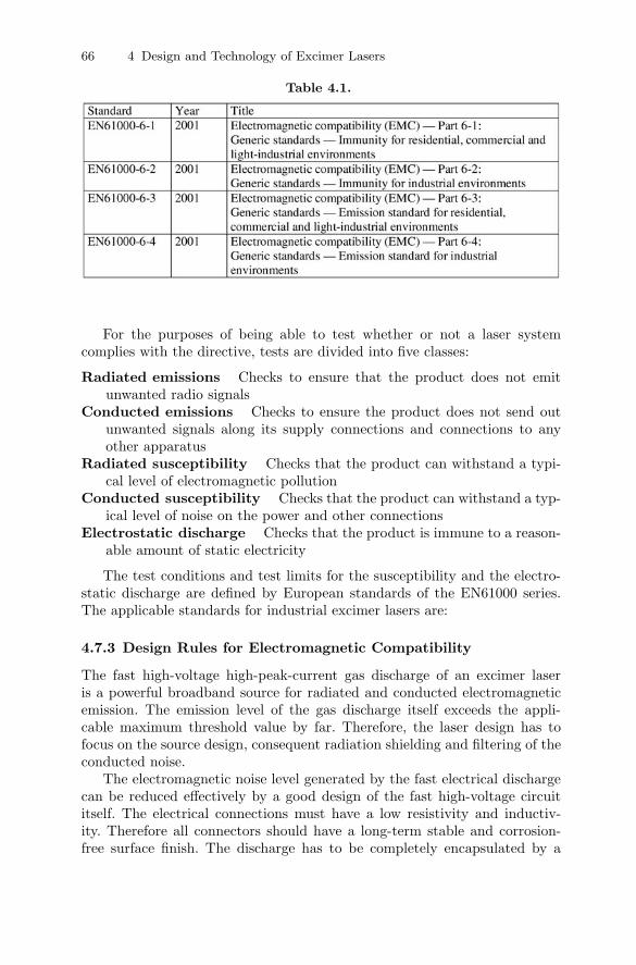
Table 4.1.
For the purposes of being able to test whether or not a laser systemcomplies with the directive, tests are divided into five classes:
Radiated emissions Checks to ensure that the product does not emitunwanted radio signals
Conducted emissions Checks to ensure the product does not send outunwanted signals along its supply connections and connections to anyother apparatus
Radiated susceptibility Checks that the product can withstand a typi-cal level of electromagnetic pollution
Conducted susceptibility Checks that the product can withstand a typ-ical level of noise on the power and other connections
Electrostatic discharge Checks that the product is immune to a reason-able amount of static electricity
The test conditions and test limits for the susceptibility and the electro-static discharge are defined by European standards of the EN61000 series.The applicable standards for industrial excimer lasers are:
4.7.3 Design Rules for Electromagnetic Compatibility
The fast high-voltage high-peak-current gas discharge of an excimer laseris a powerful broadband source for radiated and conducted electromagneticemission. The emission level of the gas discharge itself exceeds the appli-cable maximum threshold value by far. Therefore, the laser design has tofocus on the source design, consequent radiation shielding and filtering of theconducted noise.
The electromagnetic noise level generated by the fast electrical dischargecan be reduced effectively by a good design of the fast high-voltage circuititself. The electrical connections must have a low resistivity and inductiv-ity. Therefore all connectors should have a long-term stable and corrosion-free surface finish. The discharge has to be completely encapsulated by a

4.7 Safety Standards for Industrial Excimer Lasers 67
Table 4.2.
grounded return current path. The introduction of high-voltage excitationcircuits driven by all-solid-state switches further reduced the electromag-netic noise level of the fast excitation circuit significantly in comparison to athyratron-driven circuit.
A field-proven housing design concept for an excimer laser meeting theEMC standards starts with effective radiation shielding by a Faraday laserhousing made of magnetic steel. The fast gas discharge and the high voltagepower supply have to be located within one shielded compartment. Electricalgaskets must seal all panels or doors of the housing. Cooling air entries andexists must be protected by honeycomb EMC filters. The number of electricallines into and out of the Faraday cage should be reduced to the minimumnumber because an appropriate line filter, which should be located in the wallof the Faraday cage, must filter each electrical connection to and from theFaraday cage against conducted noise. Fiber optical data lines can replaceelectrical wire connections; this technique is of special interest for fast datasignals because it is difficult to filter those lines to avoid transfer of electro-magnetic noise from the shielded cabinet into the environment. These designrules result in a clear layout, avoid cumbersome electromagnetic emissionleaks and minimize the filtering costs.
A well-shielded excimer laser will pass many of the required immunitytests without special effort. Only the surge immunity and the voltage diptests bring in additional demands to the design. The surge tests normallyrequire the installation of a varistor-based mains-in module that can absorbthe high-energy pulses and protect the electronic units. The voltage dip testsadd special demands to the control electronics that must keep the laser system
68 4 Design and Technology of Excimer Lasers
in a controlled status during and after a voltage dip. A battery-buffered maincontroller is a proven approach, which enables compliance with the voltagedip standard.
Consequent EMC design of an industrial excimer laser will result in anemission level well below the low limit values for residential, commercial andlight-industrial environments. On the other hand the same laser will fulfillthe demanding immunity standards for harsh industrial environments. Anindependent EMC test laboratory normally proves compliance with the EMCstandards.
4.7.4 Low Voltage Directive 73/23/ECC
The Low Voltage Directive (LVD) 73/23/EEC is one of the oldest Europeandirectives. It was originally published in 1973 and has only one modification,93/68/EEC, published 22nd July 1993. The scope of this directive is electricalequipment designed for use within the input voltage rating 50 to 1000V ACor 75 to 1500 V DC. This directive defines the essential electrical safety andprotection requirements. This means the equipment must be safe and con-structed in accordance with the principles generally accepted as constitutinggood engineering practice in relation to safety matters.
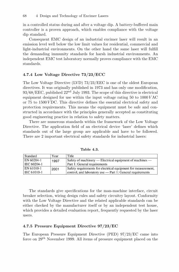
There are numerous standards within the framework of the Low VoltageDirective. The application field of an electrical device ‘laser’ defines whichstandards out of the large group are applicable and have to be followed.There are 2 important electrical safety standards for industrial lasers:
Table 4.3.
The standards give specifications for the man-machine interface, circuitbreaker selection, wiring design rules and safety circuitry layout. Conformitywith the Low Voltage Directive and the related applicable standards can beeither checked by the manufacturer itself or by an independent test house,which provides a detailed evaluation report, frequently requested by the laserusers.
4.7.5 Pressure Equipment Directive 97/23/EC
The European Pressure Equipment Directive (PED) 97/23/EC came intoforce on 29th November 1999. All items of pressure equipment placed on the

4.7 Safety Standards for Industrial Excimer Lasers 69
market in the European Economic Area after May 2002 must comply withthe directive and have evidence of compliance by carrying the CE markingas applicable. The directive provides an adequate legislative framework onEuropean level for equipment subjected to a pressure hazard.
The directive concerns manufacturers of items such as vessels, pressurizedstorage containers, heat exchangers, steam generators, boilers, industrial pip-ing, safety devices and pressure accessories. Under the community regime ofthe directive, pressure equipment and assemblies above specified pressureand/or volume thresholds must:
– be safe;– meet essential safety requirements covering design, manufacture and test-
ing;– satisfy appropriate conformity assessment procedures; and– carry the CE marking and other information.
Excimer lasers are high-pressure gas lasers and must be compliant withthis directive. The entire gas system must be designed in accordance with thisdirective and the related standards. Compliance can be achieved without theeffort of regular pressure vessel safety inspections at customer site as long asthe maximum operating temperature of the pressure system does not exceed50◦C and the stored energy of the compressed gas does not exceed 20 kJ . Agas tank of 40 l filled with 5 bar or 71 psi overpressure is just reaching thislimit.
The gas system of an excimer laser consists of the laser tube, a valvemanifold, a halogen scrubber unit, a vacuum pump and connecting tubing.The corrosive properties of the excimer laser gas mixture set strong limita-tion to the usable materials and alloys for the gas system. Flanges, valvemanifold and gas lines are normally made from stainless steel. The laser tubeas pressure vessel is typically made from a low-silicon aluminum alloy, whichmay be nickel-plated for improved resistance to halogen gas attack. The lasertube is a complex pressure vessel because some structural parts of the vesselare made from alumina and the tube has two windows typically made froma crystalline material like calcium fluoride. Calculation of the overpressurestrength of such a vessel is extremely complicated. Therefore compliance withthe standards is normally proven by an overpressure type test at 2.25 timesof the maximum nominal operating pressure.
4.7.6 Machinery Directive 89/392/EEC (Amended 98/37/EEC)
On 14th June 1989 the Council of the European Communities adopted a Di-rective (89/392/EEC) requiring the approximation of the laws of the memberstates relating to machinery. The Machinery Directive came into force on 1st
January 1993. The Second Amending Directive (93/44/EEC) was incorpo-rated into the regulations and a third Amending Directive (98/37/EC) is stillpending.
70 4 Design and Technology of Excimer Lasers
This directive defines essential general protection requirements. Thismeans the equipment must be safe and constructed in accordance with theprinciples generally accepted as constituting good engineering practice in re-lation to safety matters. Other directives such as the Low Voltage Directiveoverlap with the Machinery Directive regarding all electrical safety aspects.The European Committee for Standardization (CEN) is working to producea complex of European standards at three levels in support of the Machin-ery Directive. The first (A) level comprises general principles for the designof all types of machinery (e.g. EN 292 Mechanical Design, or EN 1050 forrisk assessment). The second (B) level covers specific safety devices and er-gonomic aspects of ranges of machinery types (e.g. EN 418 Emergency StopEquipment). Finally, the third (C) level covers specific classes of machineryby calling up the appropriate standards from the first two levels and ad-dressing requirements specific to class. To date, most of the Level A and Bstandards have been published. A specific Level C standard for excimer lasersdoes not exist and is not under preparation. Meanwhile, conformity with theessential requirements of the regulations can be demonstrated by using LevelA and B standards. Here is a list of the harmonized key standards under theMachinery Directive:
EN 292-1, -2: Safety of machinery – Basic concepts, general principles fordesign
EN 1050: Safety of machinery – Principles for risk assessmentEN 60204-1: Safety of machinery – Electrical equipment of machinesEN 954-1: Safety of machinery – Safety-related parts of control systemsEN 1088: Safety of machinery – Interlocking devices
Excimer lasers as stand-alone units do not come under the MachineryDirective but industrial excimer lasers must be compliant with the MachineryDirective because they will be integrated into a system that must complywith this directive. Compliance with the machinery directive requires a riskanalysis, and in most cases an independent test house evaluates the laser.
4.7.7 Laser Radiation Safety
Of course every laser product must fulfill the laser radiation safety require-ments. An excimer laser is by its wavelength and power always a class-IVlaser which is the highest risk class. The laser must meet the requirementsof the standard EN / IEC 60825-1:1994; Safety of laser products – Part 1:Equipment classification, requirements and user’s guide.
Compliance with laser radiation safety does not only specify design rulesfor a laser manufacturer. The EN / IEC 60825-1 standard also specifies re-sponsibility guidelines for users and operators of a laser system in order toachieve safe working conditions and laser radiation protection.

4.7 Safety Standards for Industrial Excimer Lasers 71
4.7.8 SEMI Standards
Industrial excimer lasers are frequently used in production processes of themicroelectronic and lithography industry. This industry created the Semicon-ductor Equipment and Materials Institute known as SEMI. It developed itsown standards applicable to semiconductor industry equipment. The SEMIstandards partially overlay with the CE safety standards and North Americansafety standards like NFPA 79 Electrical Standard for Industrial Machinery.
The SEMI S2 standard (SEMI S2-0703a Environmental, Health,and Safety Guideline for Semiconductor Manufacturing Equip-ment) is the most important SEMI standard for industrial excimer lasersystems. This standard has a very broad scope and covers environmental as-pects, general safety, and health guidelines. An industrial excimer laser hasto be evaluated for SEMI S2 compliance regarding the following issues:
– Documents provided to user:The requirements are specified by the standard SEMI S13-0298 SafetyGuidelines for Operation and Maintenance Manuals used withSemiconductor Manufacturing Equipment.
– Hazard warning labels:The standard SEMI S1-0701 Safety Guideline for EquipmentSafety Labels defines three safety label levels, which are distinguish-able by the key words Danger, Warning, or Caution. The labels have acommon layout and the usage of pictographs is strongly recommended.
– Safety interlock systems:This chapter specifies the requirements for the laser beam shutter andother interlocks. In general the interlocks must be of fail-safe type andclear operator information is required in case of any activation.
– Emergency shutdown:This chapter defines design rules for emergency off circuitries.
– Electrical design:The electrical design of the entire laser has to be in accordance withelectrical safety standards like EN 60204-1 or NFPA79.
– Fire protection:The latest revision of the SEMI S2 standard included new requirementsregarding fire protection. A fire risk assessment of a laser system accordingto the standard SEMI S14-0200E Safety Guidelines for Fire RiskAssessment and Mitigation for Semiconductor ManufacturingEquipment must be carried out. This can only be done by an especiallycertified test house.
– Ergonomics and human factors:Detailed specifications are given in the standard SEMI S8-1103 SafetyGuidelines for Ergonomics Engineering of Semiconductor Man-ufacturing Equipment. The focus of this standard is ergonomics andhuman factors for operators, for example accessibility of control elements

72 4 Design and Technology of Excimer Lasers
for operators, and maintenance and service personnel, for example designof laser housing panels and component access.
– Hazardous energy isolation:This chapter gives design rules for laser operation, maintenance and ser-vice. In each case access to dangerous mechanical or electrical energy mustbe prohibited by the housing design.
– Mechanical design:The mechanical design of the laser housing must prevent access to dan-gerous parts like rotating shafts or hot surfaces. All structural elementsmust be designed with sufficient strength for the intended usage. Corro-sion resistance and pressure safety must be considered for all pressurizedsystems.
– Seismic protection:The laser system must have provisions for anchorage the housing to thebuilding. The strength of the anchorage must be proven by a stabilitycalculation.
– Environmental considerations:This chapter gives guidelines for resource conversation, chemical selectionand prevention and control of unintended chemical release.
– Exhaust ventilation:Excimer lasers are supplied with toxic gases and have a toxic gas inven-tory. Therefore, the laser housing has to be properly ventilated for safetyreasons. A small under-pressure within all laser compartments containingparts of the laser gas system achieves this. The design of the laser hous-ing and proper ventilation of all critical parts is tested according to thestandard SEMI F15-93 Test Method for Enclosures Using SulfurHexafluoride Tracer Gas and Gas Chromatography.
– Chemicals:The manufacturer has to list the chemical inventory and to provide arisk analysis. Engineering controls and administrative controls have to betaken to minimize any risk.
– Non-ionizing radiation and fields:This chapter covers electromagnetic compatibility as discussed for the CEmark.
– Lasers:This chapter covers laser safety.
– Sound pressure level:This chapter specifies the acceptable sound pressure level for operation,maintenance and service.
Compliance with the SEMI S2 and related standards is mandatory for equip-ment acceptance by major companies of the semiconductor industry. Com-pliance is normally proven by a third-party evaluation report.
References 73
References
1. S. Altmeyer: RWTH Aachen (1993)2. R.S. Taylor: Appl. Phys. B 41, 1–24 (1986)3. G. Gallant, E.S. Williams, R.W. Weeks: (1992), “Excimer laser”, US patent
5,081,6384. V. Hasson, H.M. von Bergmann: J. Phys E: Scientific Instruments 9, 73–76
(1976)5. V.M. Borisov, O.B. Khristoforov, Yu.B. Kiryukhin, et al.: Proc. SPIE 3574,
56–66 (1998)6. W. Rogowski: Arch. Elektrotech. 12, 1 (1923)7. E.A. Stappaerts: Appl. Phys. Lett. 40, 1018 (1982)8. F. Ciocci, T.W.P.M. Hermsen: ENEA Report RT/TIB/89/32 (1989)9. R.G. Morton: (2004), “Discharge laser with porous insulating layer covering
anode discharge surface”, US-Patent 6,711,20210. R.G. Morton, T.S. Dyer, T.D. Steiger, R.C. Ujazdowski, T.A. Watson,
B. Moosman, A.P. Ivaschenko: (2004), “High rep-rate laser with improvedelectrodes”, US-Patent 6,690,706
11. R.G. Morton, T.S. Dyer, T.D. Steiger, R.C. Ujazdowski, T.A. Watson,B. Moosman, A.P. Ivaschenko, W. Gillespie, C. Rettig: (2004), “High rep-ratelaser with improved electrodes”, US-Patent Application 20040022292
12. J. Baumler, M. Zeh: (1989), “Electrode for pulsed gas laser”, US-Patent4,860,300
13. T.S. Dyer, R.G. Morton, W.D. Gillespie, T.D. Steiger: (2004), “Anodes forfluorine gas discharge lasers”, US-Patent Application 20040071178
14. H.M. von Bergmann, P.H. Swart: IEE Proc. B 139, 123 (1992)15. W.H. Long, M.J. Plummer, E.A. Stappaerts: Appl. Phys. Lett. 43, 735 (1983)16. W.S. Melville: Proc of the IEE 98 185 (1951)17. P.H. Swart, H.M. von Bergmann: “Comparative evaluation of pulsing circuits
for kHz excimer laser systems”, in Proc. 7th IEEE Pulsed Power Conf., Mon-terey, California (1989), pp. 293–296
18. D. Basting, K. Hohla, E. Albers, H.M. von Bergmann: Laser und Optoelek-tronik 16, 128 (1984)
19. J.W. Gerritsen, A.L. Keet, G.J. Ernst, W.J. Wittemann: J. Appl. Phys. 67,3517 (1990)
20. R.S. Taylor, K.E. Leopold: J. Appl. Phys. 65, 22 (1989)21. B. Lacour, C. Vannier: J. Appl. Phys. 62, 754 (1987)22. S. Bollanti, P. DiLazzaro, F. Flora, G. Giordano, T. Hermsen, T. Letardi, C.E.
Zheng: Appl. Phys. B 50, 415 (1990)23. B. Lacour, H. Besaucele, H. Brunet, C. Gagnol, B. Vincent: Proc. SPIE 3092,
362–365 (1996)24. G.N. Glasoe, J.V. Lebacqz: Pulse Generators (Dover, New York, 1965)25. P. Swart, G. Bredenkamp, H.M. von Bergmann: “A resonant pulsed power
supply with pulse-energy regulation”, in Proc. 6th IEEE Pulsed PowerConf Arlington, Virginia (1987), pp. 723–726
26. P.H. Swart, H.M. von Bergmann: Proc. SPIE 1397(2), 559–562 (1990)27. Lambda EMI Corp.: (2002), “Regulations and Repeatability, Application Note
402”28. G.L. Bees, A. Tydeman: “Capacitor charging power supply design for high
pulse-to-pulse repeatability applications”, in IEEE Pulsed Power Conference(1999)