Embed Size (px)
Citation preview

PROUDLY MADE IN THE
USA
Ce
rtified Company
ISO9001:2008
EX100/200 Series Insertion Magnetic Flow Meter
Instructions
EX11xEX21x
EX15xEX25x
EX100/200 SERIES INSTRUCTIONS
Seametrics • 253.872.0284 Page 2 seametrics.com
TABLE OF CONTENTS
General Information General Information ...................................................................................................................................................Page 3Features ...........................................................................................................................................................................Page 3Specifications ................................................................................................................................................................Page 4
Installation Positioning the Meter ................................................................................................................................................Page 5Immersion .......................................................................................................................................................................Page 5Chemical Injection or Fertigation ..........................................................................................................................Page 5EX11x/21x Installation ................................................................................................................................................Page 6 EX15x/25x Installation ................................................................................................................................................Page 6 Depth Setting ................................................................................................................................................................Page 7Pipe Wall Thickness .....................................................................................................................................................Page 8Straight Pipe Recommendations ...........................................................................................................................Page 9Full Pipe Recommendations ....................................................................................................................................Page 10
Electrical ConnectionsGeneral Electrical Guidelines ...................................................................................................................................Page 11Power ................................................................................................................................................................................Page 11Output ..............................................................................................................................................................................Page 11Grounding Guidelines ................................................................................................................................................Page 11
Connection DiagramsCounter or PLC ..............................................................................................................................................................Page 12A055 4-20 mA Output ...............................................................................................................................................Page 12FT520 Controller...........................................................................................................................................................Page 12FT430/440 Display & Proportional Feed ............................................................................................................Page 13FT440 & 4-20 mA Output ........................................................................................................................................Page 13Dual FT430/440 Displays ..........................................................................................................................................Page 13DL76 Data Logger .......................................................................................................................................................Page 14FT440/DL76 ....................................................................................................................................................................Page 14
Operation & MaintenanceZero Adjustment ..........................................................................................................................................................Page 15 Minimum Flow ..............................................................................................................................................................Page 15 Filtering ............................................................................................................................................................................Page 15 Electrode Coating ........................................................................................................................................................Page 15 Calibration (“K-Factor”) .............................................................................................................................................Page 15 Flow Rates in Gallons Per Minute ..........................................................................................................................Page 15Parts List ..........................................................................................................................................................................Page 16
TroubleshootingProblems .........................................................................................................................................................................Page 17Probable Causes ...........................................................................................................................................................Page 17Things to Try ..................................................................................................................................................................Page 17

EX100/200 SERIES INSTRUCTIONS
Seametrics • 253.872.0284 Page 3 seametrics.com
The EX100/200-Series are adjustable depth insertion magmeters that fit 3” to 48” pipe (up to 72” optional). The complete lack of moving parts of the EX100/200-Series is the source of its reliability. Brass and stainless steel models withstand a variety of temperature, pressure, and chemical conditions. The EX-Series has no rotor to stop turning in dirty water and there are no bearings to wear out. Like all magmeters, when used in chemical injection applications, these meters should be installed upstream of the chemical line (or far enough downstream to allow complete mixing of fluids before the meter). Adapters mate with standard 1-1/2” (11x/21x) or 2” (15x/25x) FNPT threaded fittings such as saddles and weldolets which may be purchased either locally or from Seametrics.
A rapidly reversing magnetic field is produced in the lower housing. As the fluid moves through this field, a voltage is generated that is measured and translated into a frequency signal proportional to flow rate. This square wave signal can be sent directly to a PLC or other control or can be
GENERAL INFORMATION
Features
converted using any of the Seametrics family of indicators and converters.
A modular system of electronics can be installed directly on the flow sensor or mounted remotely. The FT430 (externally powered with pulse) and the FT440 (loop powered), both provide digital rate and total displays, as well as a programmable pulse; the FT440 also provides a 4-20 mA analog output. The AO55 is a blind analog (4-20 mA) transmitter. Programmable pulse for pump pacing is available with the PD10.
The “hot-tap” models (EX15x/25x) can be installed or serviced without shutting down the line by means of a 2” full-port isolation valve that comes with a nipple for installation on the pipe fitting; a bronze ball valve is standard, with a 316 stainless steel valve option if needed. In most circumstances, no special tool is required.
Reverse flow output and immersibility are optional.
Cover or Electronics Module
Powder-Coated Cast Aluminum Housing
Sensor Housing
3/4” tubing, low insertion force (Typically no tool required)
Adapter mates with threaded fittingFNPT 1 1/2” FNPT 2”
Compression Nut for easy adjustment, secure locking
Cable Gland Strain Relief
Electrodes and Cap
Housing Screw (connect one to ground)
Cable Gland Strain Relief
Valve Assembly for hot-tap installation
2” Adapter (removes to mount hot-tap machine)
Locking Collar
EX11x/21xEX15x/25x
EX100/200 SERIES INSTRUCTIONS
Seametrics • 253.872.0284 Page 4 seametrics.com
GENERAL INFORMATION
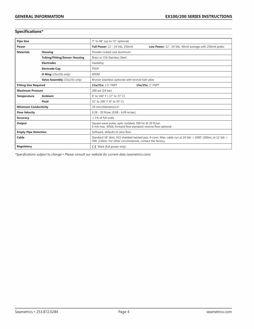
Specifications*
*Specifications subject to change • Please consult our website for current data (seametrics.com).
Pipe Size 3” to 48” (up to 72” optional)
Power Full Power: 12 - 24 Vdc, 250mA Low Power: 12 - 24 Vdc, 40mA average with 250mA peaks
Materials Housing Powder-coated cast aluminum
Tubing/Fitting/Sensor Housing Brass or 316 Stainless Steel
Electrodes Hastelloy
Electrode Cap PVDF
O-Ring (15x/25x only) EPDM
Valve Assembly (15x/25x only) Bronze (stainless optional) with bronze ball valve
Fitting Size Required 11x/21x: 1.5” FNPT 15x/25x: 2” FNPT
Maximum Pressure 200 psi (14 bar)
Temperature Ambient 0˚ to 160˚ F (-17˚ to 72˚ C)
Fluid 32˚ to 200˚ F (0˚ to 93˚ C)
Minimum Conductivity 20 microSiemens/cm
Flow Velocity 0.28 - 20 ft/sec (0.08 - 6.09 m/sec)
Accuracy ± 1% of full scale
Output Square wave pulse, opto-isolated, 500 Hz @ 20 ft/sec6 mA max, 30Vdc forward flow standard; reverse flow optional
Empty Pipe Detection Software, defaults to zero flow
Cable Standard 18’ (6m), #22 shielded twisted pair, 4-conn. Max. cable run at 24 Vdc = 1000’ (300m); at 12 Vdc = 500’ (150m). For other circumstances, contact the factory.
Regulatory Mark (full power only)
EX100/200 SERIES INSTRUCTIONS
Seametrics • 253.872.0284 Page 5 seametrics.com
Positioning the Meter
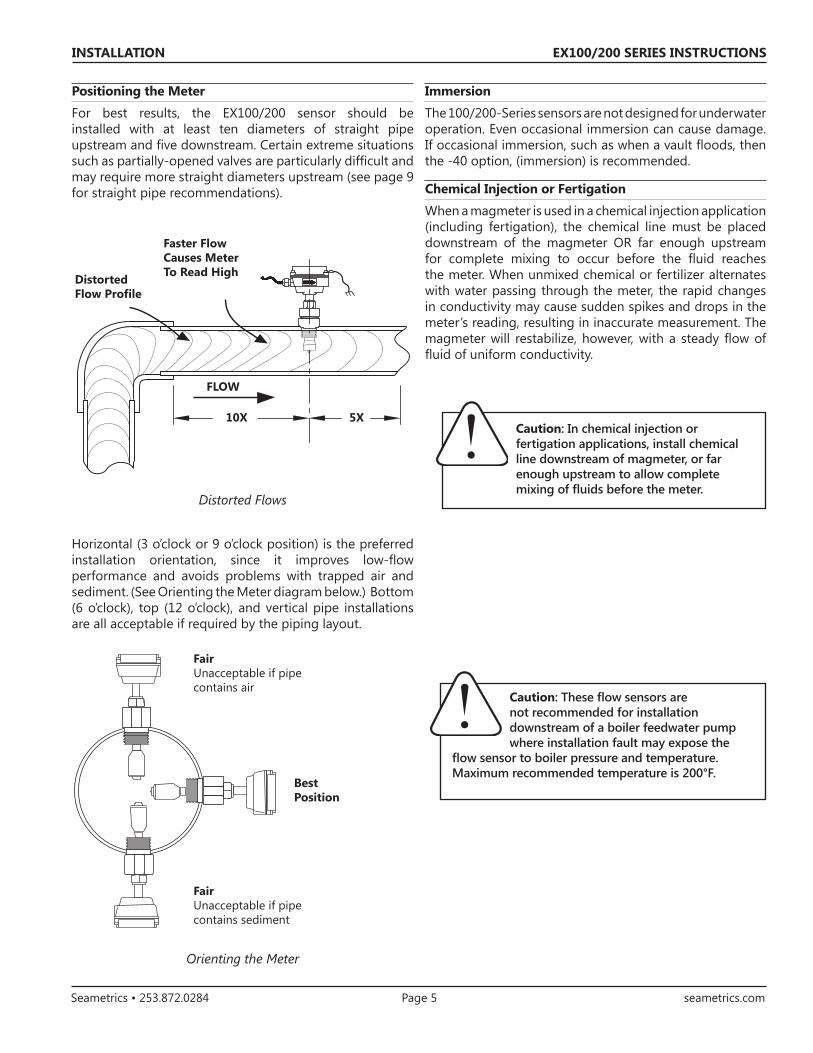
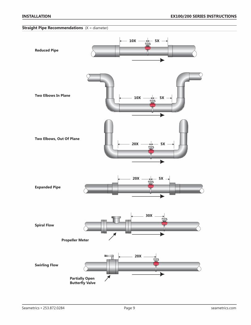
For best results, the EX100/200 sensor should be installed with at least ten diameters of straight pipe upstream and five downstream. Certain extreme situations such as partially-opened valves are particularly difficult and may require more straight diameters upstream (see page 9 for straight pipe recommendations).
Distorted Flows
Horizontal (3 o’clock or 9 o’clock position) is the preferred installation orientation, since it improves low-flow performance and avoids problems with trapped air and sediment. (See Orienting the Meter diagram below.) Bottom (6 o’clock), top (12 o’clock), and vertical pipe installations are all acceptable if required by the piping layout.
Orienting the Meter
FLOW
Faster FlowCauses MeterTo Read High
10X 5X
DistortedFlow Profile
Fair Unacceptable if pipe contains air
BestPosition
Fair Unacceptable if pipe contains sediment
Caution: These flow sensors are not recommended for installation downstream of a boiler feedwater pump where installation fault may expose the
flow sensor to boiler pressure and temperature. Maximum recommended temperature is 200°F.
INSTALLATION
Caution: In chemical injection or fertigation applications, install chemical line downstream of magmeter, or far enough upstream to allow complete mixing of fluids before the meter.
Immersion
The 100/200-Series sensors are not designed for underwater operation. Even occasional immersion can cause damage. If occasional immersion, such as when a vault floods, then the -40 option, (immersion) is recommended.
Chemical Injection or Fertigation
When a magmeter is used in a chemical injection application (including fertigation), the chemical line must be placed downstream of the magmeter OR far enough upstream for complete mixing to occur before the fluid reaches the meter. When unmixed chemical or fertilizer alternates with water passing through the meter, the rapid changes in conductivity may cause sudden spikes and drops in the meter’s reading, resulting in inaccurate measurement. The magmeter will restabilize, however, with a steady flow of fluid of uniform conductivity.

EX100/200 SERIES INSTRUCTIONS
Seametrics • 253.872.0284 Page 6 seametrics.com
Fitting Installation. EX11x/21x adapters mate with a 1-1/2” female NPT pipe thread adapter fitting. Any fitting that provides the matching NPT female thread may be used. Installation procedure compensates for fitting height differences. Cut a minimum 1-3/4” hole in the pipe. If possible, measure the wall thickness and write it down for use in depth setting. Then install the threaded fitting (saddle, weldolet, etc.) on the pipe.
Meter Installation. Loosen the compression nut so that the adapter slides freely. Pull the meter fully upward and finger-tighten the compression nut. Using a thread sealant, install the adapter in the pipe fitting. Do not overtighten. Now loosen the compression nut, lower the meter to the appropriate depth setting (see diagram and instructions that follow). Be sure flow is in the direction of the arrow on the housing. Fully tighten compression nut.
‘Hot tap’ EX meters are designed so they can be installed and serviced without depressurizing the pipe.
Fitting Installation. The EX15x/25x adapters mate with a 2” FNPT threaded fitting for compatibility with the 2” isolation valve. Any fitting that provides matching NPT female thread may be used. The installation procedure compensates for differences in fitting height.
If initial installation is performed on an unpressurized pipe, cut a minimum 1-3/4” hole in the pipe. If possible, measure the wall thickness and write it down for use in depth setting. Then install the threaded fitting (saddle, weldolet, etc.) on the pipe.
If it is necessary to do the initial installation under pressure, any standard hot tap drilling machine with 2” NPT adapter, such as a Transmate or a Mueller, can be used. Ordinarily, it is not necessary to use an installation tool, due to the small diameter tube the meter can be installed by hand at all but the highest pressures.
Meter Installation. Remove the sensor unit from the valve assembly. Using a thread sealant, install the valve assembly on the pipe fitting. If the initial installation is a pressure (“hot”) tap, remove the 1-1/2” x 2” adapter bushing at the back of the valve. Thread the tapping machine on, open the valve, and tap using a minimum of 1-3/4” or maximum 1-7/8” cutter. After retracting the machine and closing the valve, reinstall the flow sensor. When the sensor is secure, open the valve and adjust depth setting (see diagram and instructions that follow). Be sure flow is in the direction of the arrow on the housing. Fully tighten locking collar and compression nut.
INSTALLATION
Compression nut
Adapter mates withFNPT threads
EX15x/25x Sensor Removal
Compression nut
2” adapter removes to mount hot-tap machine
Full-port 2” ball valve allows sensor removal
Mates with 2” FNPT threads
Locking collar
EX11x/21x Installation
EX15x/25x Installation
EX100/200 SERIES INSTRUCTIONS
Seametrics • 253.872.0284 Page 7 seametrics.com
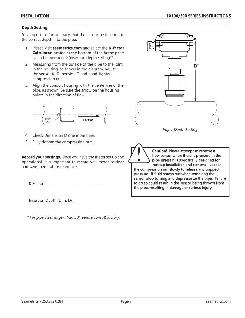
“D”
It is important for accuracy that the sensor be inserted to the correct depth into the pipe.
1. Please visit seametrics.com and select the K-factor Calculator located at the bottom of the home page to find dimension D (insertion depth setting)*.
2. Measuring from the outside of the pipe to the joint in the housing, as shown in the diagram, adjust the sensor to Dimension D and hand-tighten compression nut.
3. Align the conduit housing with the centerline of the pipe, as shown. Be sure the arrow on the housing points in the direction of flow.
4. Check Dimension D one more time.
5. Fully tighten the compression nut.
Record your settings. Once you have the meter set up and operational, it is important to record you meter settings and save them future reference.
K-Factor ___________________________________
Insertion Depth (Dim. D) __________________
* For pipe sizes larger than 50”, please consult factory.
strain relief FLOW
INSTALLATION
Caution! Never attempt to remove a flow sensor when there is pressure in the pipe unless it is specifically designed for hot tap installation and removal. Loosen
the compression nut slowly to release any trapped pressure. If fluid sprays out when removing the sensor, stop turning and depressurize the pipe. Failure to do so could result in the sensor being thrown from the pipe, resulting in damage or serious injury.
Depth Setting
Proper Depth Setting

EX100/200 SERIES INSTRUCTIONS
Seametrics • 253.872.0284 Page 8 seametrics.com
Pipe Wall Thickness
INSTALLATION
Nominal Pipe Size*
3" 4" 6" 8" 10" 12" 14" 16" 18" 20" 24" 30" 36"
Schedule 40 0.216 0.237 0.280 0.322 0.365 0.406 0.438 0.500 0.562 0.593 0.687 -- --
Schedule 80 0.300 0.337 0.432 0.500 0.593 0.687 0.750 0.843 0.937 1.031 1.218 -- --
Stainless Steel (10S) 0.120 0.120 0.134 0.148 0.165 0.180 0.188 0.188 0.188 0.218 0.250 0.312 0.312
Stainless Steel (40S) 0.216 0.237 0.280 0.322 0.365 0.375 0.375 0.375 0.375 0.375 0.375 0.375 0.375
Copper Tubing (Type L) 0.090 0.100 0.140 0.200 0.250 0.280 -- -- -- -- -- -- --
Copper Tubing (Type K) 0.109 0.134 0.192 0.271 0.338 0.405 -- -- -- -- -- -- --
Brass Pipe 0.219 0.250 0.250 0.312 0.365 0.375 -- -- -- -- -- -- --
Duct. Iron (Class 52) 0.280 0.290 0.310 0.330 0.350 0.370 0.390 0.400 0.410 0.420 0.440 0.470 0.530
* Call factory for larger pipe sizes.
EX100/200 SERIES INSTRUCTIONS
Seametrics • 253.872.0284 Page 9 seametrics.com
INSTALLATION
Straight Pipe Recommendations (X = diameter)
5X10X
Reduced Pipe
Two Elbows In Plane
Two Elbows, Out Of Plane
Expanded Pipe
Swirling Flow
Propeller Meter
Partially OpenButterfly Valve
Spiral Flow
5X
5X
20X
20X
30X
20X
5X10X

EX100/200 SERIES INSTRUCTIONS
Seametrics • 253.872.0284 Page 10 seametrics.com
INSTALLATION
Caution: These flow sensors are not recommended for installation downstream of a boiler feedwater pump where installation fault may expose the flow sensor to boiler pressure and temperature. Maximum recommended temperature is 200°F.
Full Pipe Recommendations
Better InstallationPossible Problem
Air can be trapped Allows air to bleed off
Better InstallationPossible Problem
Allows air pockets to form at sensor Ensures full pipe
Post-valve cavitation can create air pocket Keeps pipe full at sensor
Better InstallationPossible Problem

EX100/200 SERIES INSTRUCTIONS
Seametrics • 253.872.0284 Page 11 seametrics.com
Grounding Guidelines:
For best results, use a good quality earth ground, such as metallic water piping or a driven ground, to ensure a good connection to earth ground and good noise suppression.
If the flow sensor is installed in metallic piping, for optimum connection clamp wire to the piping a short distance to one side of the flow sensor using an electrical grounding clamp. Connect the wire to the earth ground and to one of the housing screws.
For Non-Metallic Pipe: Connect one to the housing screws by wire to a good earth ground, such as metalic water piping or a rod driven into the ground.
EX meters are usually unaffected by moderate levels of electrical noise. In some applications performance may be improved by taking the following steps:
• Use shielded twisted pair cable (Belden 8723 or equivalent above ground or Alpha 35482 or equivalent burial).
• Clamp a ferrite bead (Steward 28A2029-OAO or equivalent) on meter signal/power wire within 3/4” of the meter strain relief (tape or tie wrap in place if necessary). See diagram below.
• IMPORTANT - Connect the cable shield ground wire to ground, ONLY at power supply end of cable.
General Electrical Guidelines
• Whenever possible avoid running control cables in the same conduit with or bundled with AC power.
• Using shielded cable, be sure to connect shield to ground at power supply end of the cable. Do not connect other end of shield.
• Avoid routing flow sensor cables in close proximity to a variable frequency drive.
• Recommended power and output wiring is shielded twisted pair 18-22 AWG control cable.
• Recommended voltage is 12-24 Vdc. Note that unregulated power supplies can vary from nameplate voltage by a considerable amount, especially with AC line voltage fluctuation. Therefore 24V power supplies must be regulated.
See the Connections diagrams on the following pages for the appropriate terminals.
Power
A 12 - 24 Vdc power supply capable of at least 250 mA current output is needed.
Output
The standard output is pulses with flow in the forward direction (Reverse flow output is optional [-15] ). Electrically it is an open collector opto isolated switch. The output is not internally powered.
Note: This output is limited to 6 mA at 30 Vdc maximum.
Caution: The EX100/200-Series have strong start and run currents. When using solar panels and VRSLA batteries as a power source, use caution to insure the EX-
series sensor has the -50 Low-power Option and that all Seametrics products on the power circuit receive sufficient voltage and current under all conditions. Failure to do so will lead to unreliable operation and possible damage to the unit/s. Please reference the technical bulletin, ‘Solar and Battery-Power Guildlines’ available on our website: www.seametrics.com
ELECTRICAL CONNECTIONS
Earth Ground
Grounding Clamp
Place Ferrite Bead Here
Housing Screw
Metallic Pipe

EX100/200 SERIES INSTRUCTIONS
Seametrics • 253.872.0284 Page 12 seametrics.com
CONNECTIONS DIAGRAMS
+_
+_
009
87 6 5 4
321 009
87 6 5 4
321 009
87 6 5 4
321 009
87 6 5 4
321
+
_S +
_+
_
+ _
+
+_
_
+_
+
+_
_
+_
+ _
Counter or PLC
AO55 4-20 mA Output
FT520 Controller
Power
Forward Output(open collector)
Reverse Output(Option -15 only)
12 - 24 Vdc
Max. 6 mA, 30 Vdc
Power
Forward Output
EX-SERIES
AO55
EX-SERIES
Sensor
4-20 mA
4-20 mA
24 Vdc Power
+12VSEN1
GSEN2
EX-SERIES
24 Vdc Power
Power
Forward Output
FT520
Reverse Output(Option-15 only)
Reverse Output(Option-15 only)
+–
+–
Max. 6 mA 30 Vdc
PulseOut
See Dual FT430/440 Diagram for anexample of bidirectional connections.
See Dual FT430/440 Diagram for anexample of bidirectional connections.
Frequency
See Dual FT430/440 Diagram for anexample of bidirectional connections.
Counter or PLC Digital Input
24 Vdc Power
Red
Green
White
Blac
k
Red Bl
ack
Blac
k Red
Green
White
EX100/200 SERIES INSTRUCTIONS
Seametrics • 253.872.0284 Page 13 seametrics.com
CONNECTIONS DIAGRAMS
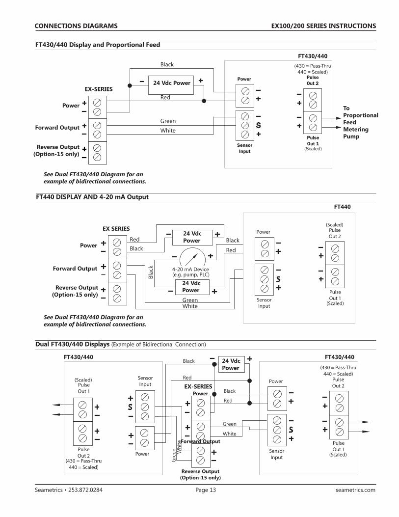
FT430/440 Display and Proportional Feed
FT440 DISPLAY AND 4-20 mA Output
+_
+
+_
_
+_
+
_S
+_
+_
+_
Power PulseOut 2
SensorInput
PulseOut 1
(Scaled)
(430 = Pass-Thru440 = Scaled)
Power
Forward Output
EX-SERIES24 Vdc Power
ToProportional FeedMetering Pump
FT430/440
See Dual FT430/440 Diagram for anexample of bidirectional connections.
Reverse Output(Option-15 only)
Red
Green
White
Black
See Dual FT430/440 Diagram for anexample of bidirectional connections.
+
+_
_
+_
+_
+_+_
+
_S
+_
+_
+_
Power PulseOut 2
SensorInput
PulseOut 1
(Scaled)
(Scaled)
Reverse Output(Option-15 only)
Power
Forward Output
EX SERIES24 VdcPower
FT440
24 Vdc Power
BlackRed
GreenWhite
Black
Red
Blac
k 4-20 mA Device (e.g. pump, PLC)
Dual FT430/440 Displays (Example of Bidirectional Connection)
+
_S
+_
+_
+_
Power PulseOut 2
SensorInput
PulseOut 1
(Scaled)
(430 = Pass-Thru440 = Scaled)
+
_S
+_
+_
+_
PowerPulseOut 2
SensorInputPulse
Out 1
(Scaled)
(430 = Pass-Thru440 = Scaled)
Reverse Output(Option-15 only)
Power
Forward Output
24 Vdc Power
FT430/440FT430/440
Black
Red
Green
White
Red
Black
Gre
en Whi
te
EX-SERIES
EX100/200 SERIES INSTRUCTIONS
Seametrics • 253.872.0284 Page 14 seametrics.com
CONNECTIONS DIAGRAMS
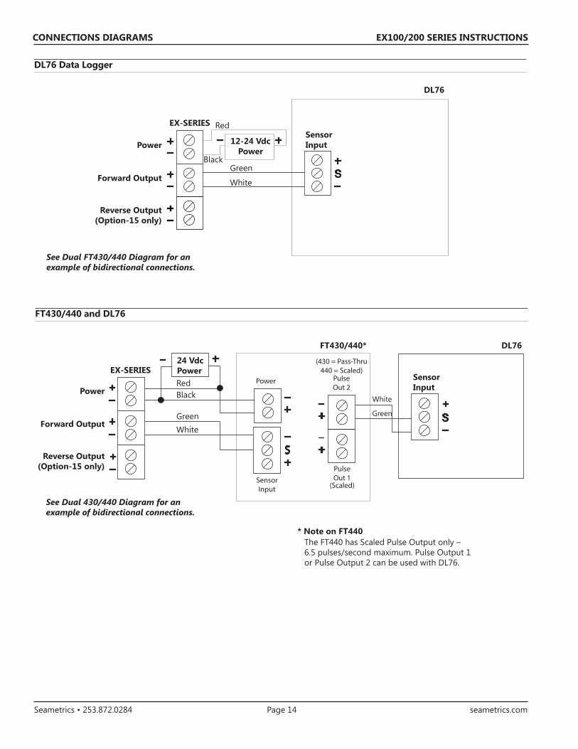
DL76 Data Logger
FT430/440 and DL76
Reverse Output(Option-15 only)
Power
Forward Output
SensorInput
DL76
EX-SERIES
See Dual FT430/440 Diagram for anexample of bidirectional connections.
Green
White
Black
Red
12-24 VdcPower
+
_S
+
+_
_
+_
+_
+
_S
+_
+_
+_
Power PulseOut 2
SensorInput
PulseOut 1
(Scaled)
(430 = Pass-Thru440 = Scaled)
24 Vdc Power
DL76FT430/440*
EX-SERIESSensorInput
Reverse Output(Option-15 only)
Power
Forward Output
See Dual 430/440 Diagram for anexample of bidirectional connections.
Red
GreenWhite
Green
WhiteBlack
* Note on FT440 The FT440 has Scaled Pulse Output only – 6.5 pulses/second maximum. Pulse Output 1 or Pulse Output 2 can be used with DL76.
EX100/200 SERIES INSTRUCTIONS
Seametrics • 253.872.0284 Page 15 seametrics.com
Flow Rates (in gallons per minute)
OPERATION & MAINTENANCE
Filtering
The software of the EX100/200-Series filters out electrical noise and averages sudden variations in the flow to smooth the output. It takes a matter of seconds for the flow sensor to get up to full output when it is powered up or when flow begins.
Electrode Coating
Grease or other adhering, non-conductive materials can stop flow detection if the electrodes become heavily coated. To clean the electrodes, remove the sensor from the pipe and gently scrub the electrodes (three silver bumps) on the reading face of the flow sensor. A mild soap (dishwashing liquid for example) can be used to aid the cleaning process.
Calibration (“K-Factor”)
In order to properly process pulses from the flow sensor, a number must be entered into the control to which the sensor is connected. This number, called the K-factor, is the number of pulses the sensor puts out per unit of fluid passing through the pipe. It is normally provided for Seametrics sensors in pulses per gallon, and can be ascertained by using the “K-Factor Calculator” on the Seametrics website. These numbers are based on extensive testing, which has shown close agreement among different EX sensors in the same installation. Typically, most K-factor error can be attributed to installation variables, such as depth setting and fitting configuration.
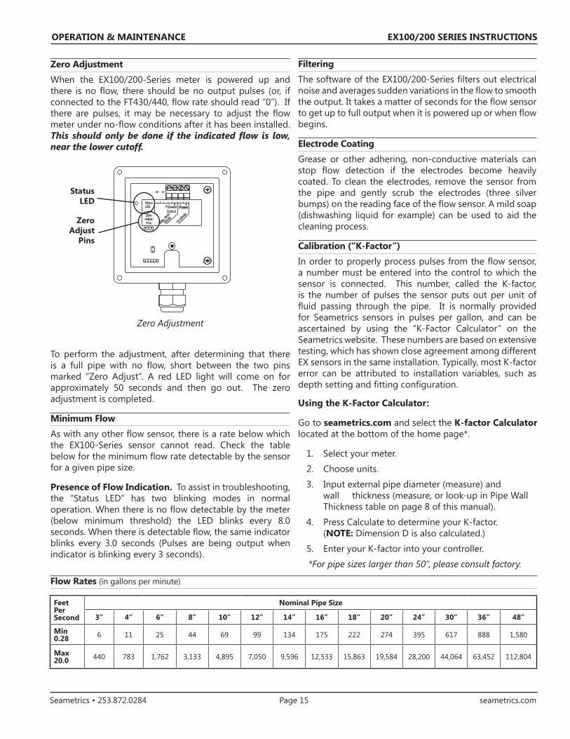
Zero Adjustment
When the EX100/200-Series meter is powered up and there is no flow, there should be no output pulses (or, if connected to the FT430/440, flow rate should read “0”). If there are pulses, it may be necessary to adjust the flow meter under no-flow conditions after it has been installed. This should only be done if the indicated flow is low, near the lower cutoff.
Zero Adjustment
To perform the adjustment, after determining that there is a full pipe with no flow, short between the two pins marked “Zero Adjust”. A red LED light will come on for approximately 50 seconds and then go out. The zero adjustment is completed.
Minimum Flow
As with any other flow sensor, there is a rate below which the EX100-Series sensor cannot read. Check the table below for the minimum flow rate detectable by the sensor for a given pipe size.
Presence of Flow Indication. To assist in troubleshooting, the “Status LED” has two blinking modes in normal operation. When there is no flow detectable by the meter (below minimum threshold) the LED blinks every 8.0 seconds. When there is detectable flow, the same indicator blinks every 3.0 seconds (Pulses are being output when indicator is blinking every 3 seconds).
30V
dcMax.
6mA
- +- +
12-24
Vdc
3 4 5 621
PowerForwardOutput
StatusLED
ZeroAdjustPinsZero
AdjustPins
StatusLED
Using the K-Factor Calculator:
Go to seametrics.com and select the K-factor Calculator located at the bottom of the home page*.
1. Select your meter.
2. Choose units.
3. Input external pipe diameter (measure) and wall thickness (measure, or look-up in Pipe Wall Thickness table on page 8 of this manual).
4. Press Calculate to determine your K-factor. (NOTE: Dimension D is also calculated.)
5. Enter your K-factor into your controller.
*For pipe sizes larger than 50”, please consult factory.
Feet Per Second
Nominal Pipe Size
3” 4” 6” 8” 10” 12” 14” 16” 18” 20” 24” 30” 36” 48”
Min 0.28 6 11 25 44 69 99 134 175 222 274 395 617 888 1,580
Max 20.0 440 783 1,762 3,133 4,895 7,050 9,596 12,533 15,863 19,584 28,200 44,064 63,452 112,804
EX100/200 SERIES INSTRUCTIONS
Seametrics • 253.872.0284 Page 16 seametrics.com
OPERATION & MAINTENANCE
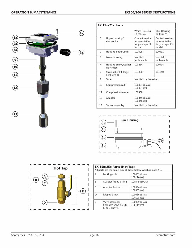
EX 11x/21x Parts
White Housing1a thru 7a
Blue Housing1b thru 7b
1 Upper housing/electronics
Contact service representative for your specific model
Contact service representative for your specific model
2 Housing gasket/seal 102005 100411
3 Lower housing Not field replaceable
Not field replaceable
4 Housing screw/washer kit (4 each)
100414 100414
7 Strain relief kit, large(includes 1)
101850 101850
9 Tube Not field replaceable
10 Compression nut 100064 (brass)100084 (ss)
11 Compression ferrule 100358
12 Adapter 100845 (brass) 100846 (ss)
13 Sensor assembly Not field replaceable
A
E
D
CB
Hot Tap
1a
11
10
9
4a
7a3a
2a
13
12
EX 15x/25x Parts (Hot Tap)All parts are the same except those below, which replace #12
A Locking collar 100061 (brass)100116 (ss)
B Adapter fitting o-ring 100345 (EPDM)
C Adapter, hot tap 100384 (brass)100385 (ss)
D Nipple, 2 inch 100066 (brass)100103 (ss)
E Valve assembly (includes valve plus B, C, & D above)
100069 (brass)100119 (ss)
Blue Housing
1b
4b
7b3b
2b

EX100/200 SERIES INSTRUCTIONS
Seametrics • 253.872.0284 Page 17 seametrics.com
Problem Probable Cause Try...
No pulse output Unit not grounded Connect to earth ground.
Below minimum flow cutoff Check the Presence of Flow LED (see page 15).
Flow reversed Note flow direction arrow, reverse direction to meter.
Output connections reversed Change output connections.
Pipe not full Check plumbing.
Excessive electrical noise Check for proper electrical wiring.
No power Check for power across power input terminals.
Power reversed Reverse connections
Fluid conductivity <20 µS/cm Select another flow meter.
Output pulses incorrect Missing or incorrect ground wire Check for proper ground.
Incorrect depth setting Check depth setting (see page 7).
Fluid conductivity <20 µS/cm Select another flow meter.
Empty pipe Check for full pipe or install meter in vertical position.
Not enough straight pipe Check for air pockets or turbulence. Refer to Installation section earlier in this manual.
Excessive electrical noise Check for proper electrical wiring.
Jumpy readings Rapidly changing conductivity (in chemical injection or fertigation applications).
Install chemical injection line downstream of magmeter (or far enough upstream to allow complete mixing of fluids before meter)
TROUBLESHOOTING

EX100/200 SERIES INSTRUCTIONS
Seametrics • 253.872.0284 Page 18 seametrics.com
NOTES

EX100/200 SERIES INSTRUCTIONS
Seametrics • 253.872.0284 Page 19 seametrics.com
NOTES

Seametrics • 19026 72nd Avenue South • Kent, Washington 98032 • USA (P) 253.872.0284 • (F) 253.872.0285 • 1.800.975.8153 • seametrics.com
LT-65200196r2.0 20160830 8/30/16