Embed Size (px)
Citation preview
EWT Universal Controller for EXZT Industrial Lubrication Systems IG IGZ IZ
Operating Manual Version V6
Imprint Seite 0 - 1
US
Imprint
The operating manual is part of the scope of supply of VOGEL universal controllers for indus-trial lubrication systems. The manual has been edited in conformity with applicable standards and rules for technical documentation. © Copyright WILLY VOGEL AG reserves the right to make changes to adapt to technical improvement. Reprinting or copying even of parts of this man-ual requires the permission of WILLY VOGEL AG. Editor Dipl.-Ing. S. Schlenzka
Contents
Part 1: General Operating Manual
EC Declaration of Conformity ............... 0 - 3 Introduction ............................................ 1 - 1 Safety Instructions................................. 1 - 1 Notes Concerning this Manual ............. 1 - 2 Applications............................................ 1 - 2 Versions, Designation............................ 1 - 3 Scope of Supply ..................................... 1 - 3 Design and Function.............................. 1 - 4
Design ........................................................ 1 - 4 Function...................................................... 1 - 5 Terminal Assignment ................................. 1 - 6
Installation .............................................. 1 - 9 Operation .............................................. 1 - 10
Display Structure...................................... 1 - 10 LEDs ......................................................... 1 - 11 LCD Display.............................................. 1 - 11 The Status Display ................................... 1 - 11 The Info Display ....................................... 1 - 11 Display of input functions: ....................... 1 - 12 Adjusting the input functions................... 1 - 12 The Parameter Display ............................ 1 - 12 Setting Parameters .................................. 1 - 14
Use as Replacement ............................ 1 - 15 Failures ................................................. 1 - 16
Failure Messages ..................................... 1 - 16 Device Failures......................................... 1 - 16
Maintenance and Repair...................... 1 - 16
Specifications ....................................... 1 - 17 Service Germany .................................. 1 - 18 Service Worldwide ............................... 1 - 18
Contents Seite 0 - 2
US
Part 2: Device Descriptions
Controllers for Single-Line Lubrication Systems .................................................. 2 - 1
Application..................................................2 - 1 Overview .....................................................2 - 1 Function......................................................2 - 1 Installation...................................................2 - 3 Operation ....................................................2 - 3 Failure Messages .......................................2 - 3 EXZT2A02 ...................................................2 - 5 EXZT2A05 ...................................................2 - 7 EXZT2A07 ...................................................2 - 9 IGZ36-20, IGZ36-20-S6 ............................2 - 11 IGZ38-30, IGZ38-30-S1 ............................2 - 16 IG351-10 ...................................................2 - 21 IGZ51-20-S3..............................................2 - 23
Controllers for Oil+Air Lubrication System................. 2 - 27
Application................................................2 - 27 Overview ...................................................2 - 27 Function....................................................2 - 27 Installation.................................................2 - 28 Operation ..................................................2 - 28 Display of Failures ....................................2 - 29 IG54-20 .....................................................2 - 30 IG54-20 .....................................................2 - 31 IG54-20-S1, IG54-20-S3, IG54-20-S4 ......2 - 34
Controllers for Systems with Progressive Feeders ............................ 2 - 38
Application................................................ 2 - 38 Overview................................................... 2 - 38 Function.................................................... 2 - 38 Installation ................................................ 2 - 39 Operation.................................................. 2 - 40 Display of Failures.................................... 2 - 40 EXZT2A03................................................. 2 - 42 EXZT2A06................................................. 2 - 44 IGZ51-20................................................... 2 - 46 IGZ51-20-S2 ............................................. 2 - 50 IGZ51-20-S7 ............................................. 2 - 54 IGZ51-20-S8 ............................................. 2 - 58
Controllers for Combined Circulation and Piston Feeder Systems................. 2 - 62
Application................................................ 2 - 62 Overview................................................... 2 - 62 Function.................................................... 2 - 62 Installation ................................................ 2 - 63 Operation.................................................. 2 - 63 Failure Messages ..................................... 2 - 64 IZ361-30.................................................... 2 - 65
Pulse Monitors......................................2 - 68 Application ............................................... 2 - 68 Overview................................................... 2 - 68 Function ................................................... 2 - 68 Installation ................................................ 2 - 68 Operation ................................................. 2 - 68 Failure Messages..................................... 2 - 69 EWT2A01, EWT2A01-S1.......................... 2 - 70 EWT2A04, EWT2A04-S1.......................... 2 - 73
Controllers for Chain Lubrication Systems.............................2 - 77
Application ............................................... 2 - 77 Overview................................................... 2 - 77 Function ................................................... 2 - 77 Installation ................................................ 2 - 78 Operation ................................................. 2 - 78 Failure Messages..................................... 2 - 79 IZ52-20 ..................................................... 2 - 80
EC Declaration of Conformity Seite 0 - 3
US
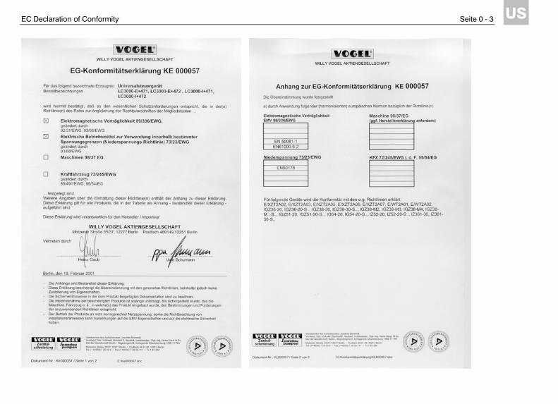
EC Declaration of Confor-mity
EWT Universal Controller for EXZT Industrial Lubrication Systems IG IGZ IZ
General Operating Manual

Introduction Page 1 - 1
US
Introduction
The product described in this manual is a con-trol and monitoring device for VOGEL central lubrication systems installed in stationary indus-trial plants. It is either supplied as a component of VOGEL compact lubrication systems or indi-vidually for installation in a control cabinet. The universal controller is the basis of all new control and monitoring devices and can also be installed to replace any of the controllers for cabinet installation that were used so far. Since the control functions may differ greatly depend-ing on plant and application, different device types based on the universal controller are of-fered. Functionally these correspond to the con-trollers so far employed. The previous designa-tions for individual devices have to a large extent remained. Table A – 1 (appendix) con-tains a list of the available device types. The VOGEL universal controller for industrial lu-brication systems has been made in conformity with the generally recognized rules of technol-ogy and the applicable safe working practices and the rules for accident prevention. To ensure trouble-free operation and prevent hazard, we kindly ask you to read the present manual care-fully and observe the notes contained in it.
Safety Instructions
The VOGEL universal controller for industrial lu-brication systems is designed for operation on industrial direct or alternating current supply (see Specifications). Other applications are not allowed. Only trained specialists capable of recognizing the hazard in connection with touching of live components are allowed to install and connect the device. The local connecting conditions and the applicable rules (e. g. DIN, VDE standards) must be observed.
If devices are improperly connected, substantial material and personal damage may be the consequence.
All adjustments on the device must be per-formed exclusively by qualified personnel. Qualified personnel has been trained, instructed and specifically ordered by the owner to per-form the work. Unauthorised alteration of the device and use of unapproved spare parts and auxiliaries are not allowed.
The housing of the device must not be opened.
If the device is failing, turn to a VOGEL service station (see chapter Service).

Notes Concerning this Manual Page 1 - 2
US
Notes Concerning this Manual
This operating manual is subdivided into three parts. The first part contains a general descrip-tion of the universal controller as well as basic instructions for installation, operation and use as replacement. The second part contains informa-tion on the differences between the individual device types. The third part contains important tables providing an overview. Use the table of contents to locate the desired information promptly and successfully. Please take note of the symbol shown below. It calls attention to special situations:
Text marked with this sign alerts to special hazard or work that must be performed with caution.
Please consider that this manual is an integral part of the device and should be handed to the new owner if the device is sold.
Applications
The universal controller is intended to control and monitor VOGEL central lubrication systems in stationary industrial plants. It must only be used for the purpose outlined in this manual. We do not assume liability for damages result-ing from unintended use of the device. The same applies if the device is used in faulty con-dition, or if the device is altered although WILLY VOGEL AG has not granted permission.
Table 1 - 1. Versions of the VOGEL Universal Controller for Industrial Lubrication Systems
Designation Description
Device type E+471 Housing for installation in control cabinet, operating voltage selectable 100..120 V AC or 200..240 V AC
Device type I+471 Housing installed in compact system, operating voltage selectable 100..120 V AC or 200..240 V AC
Device type E+472 Housing for installation in control cabinet, operating voltage 20..24 V AC or DC
Device type I+472 Housing installed in compact system, operating voltage 20..24 V AC or DC

Versions, Designation Page 1 - 3
US
Versions, Designation
The VOGEL universal controller for industrial lu-brication systems is available in four versions (table 1 - 1). The designations E and I refer to the installation location of the unit, e.g. I(nternal) inside a compact lubrication system or E(xternal) for installation in a control cabinet. The designations 471 and 472 indicate the op-erating voltage range (voltage code). Different from the designations previously used, only these two voltage codes are referenced. An overview of the voltage codes previously used and the new designations is found in table A - 2 in the appendix.
Scope of Supply
The VOGEL universal controller is supplied ei-ther installed in a compact lubrication system (version I) or individually for installation in a con-trol cabinet (version E). The scope of supply of version E includes: • a universal controller in the configuration or-
dered • two jumpers for selection of the operating
voltage range (only version E+471) • an operating manual
Design and Function Page 1 - 4
US
Design and Function
Design
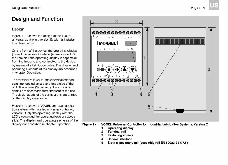
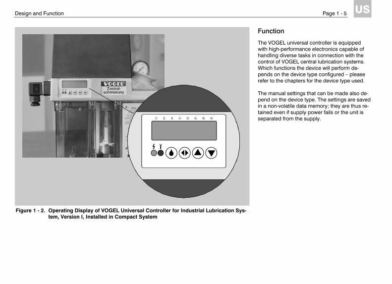
Figure 1 - 1 shows the design of the VOGEL universal controller, version E, with its installa-tion dimensions. On the front of the device, the operating display (1) and the service interface (4) are located. On the version I, the operating display is separated from the housing and connected to the device by means of a flat ribbon cable. The display and operating elements of the display are described in chapter Operation. The terminal rails (2) for the electrical connec-tions are located on top and underside of the unit. The screws (3) fastening the connecting cables are accessible from the front of the unit. The designations of the connections are printed on the display membrane. Figure 1 - 2 shows a VOGEL compact lubrica-tion system with installed universal controller, version I. Only the operating display with the LCD display and the operating keys are acces-sible. The display and operating elements of the display are described in chapter Operation.
Figure 1 - 1. VOGEL Universal Controller for Industrial Lubrication Systems, Version E 1 Operating display 2 Terminal rail 3 Fastening screws 4 Service interface 5 Slot for assembly rail (assembly rail EN 50022-35 x 7,5)
Design and Function Page 1 - 5
US
Function
The VOGEL universal controller is equipped with high-performance electronics capable of handling diverse tasks in connection with the control of VOGEL central lubrication systems. Which functions the device will perform de-pends on the device type configured – please refer to the chapters for the device type used. The manual settings that can be made also de-pend on the device type. The settings are saved in a non-volatile data memory; they are thus re-tained even if supply power fails or the unit is separated from the supply.
Figure 1 - 2. Operating Display of VOGEL Universal Controller for Industrial Lubrication Sys-tem, Version I, Installed in Compact System
Design and Function Page 1 - 6
US
Terminal Assignment
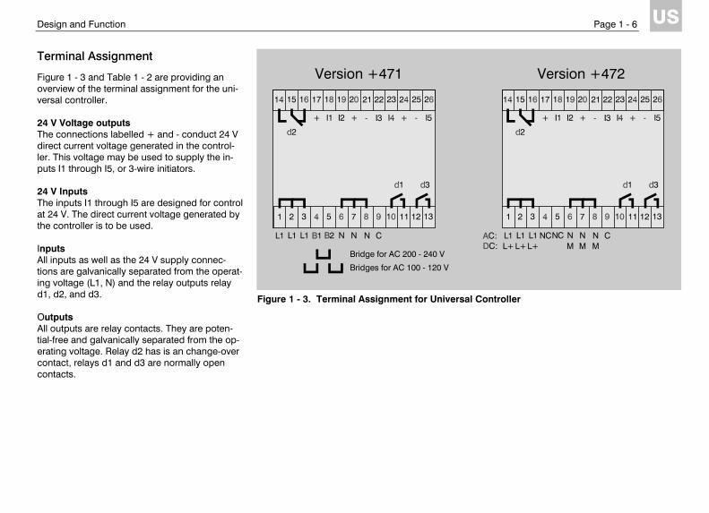
Figure 1 - 3 and Table 1 - 2 are providing an overview of the terminal assignment for the uni-versal controller. 24 V Voltage outputs The connections labelled + and - conduct 24 V direct current voltage generated in the control-ler. This voltage may be used to supply the in-puts I1 through I5, or 3-wire initiators. 24 V Inputs The inputs I1 through I5 are designed for control at 24 V. The direct current voltage generated by the controller is to be used. Inputs All inputs as well as the 24 V supply connec-tions are galvanically separated from the operat-ing voltage (L1, N) and the relay outputs relay d1, d2, and d3. Outputs All outputs are relay contacts. They are poten-tial-free and galvanically separated from the op-erating voltage. Relay d2 has is an change-over contact, relays d1 and d3 are normally open contacts.
Figure 1 - 3. Terminal Assignment for Universal Controller
Version +472 Version +471
Bridge for AC 200 - 240 V
Bridges for AC 100 - 120 V
Design and Function Page 1 - 7
US
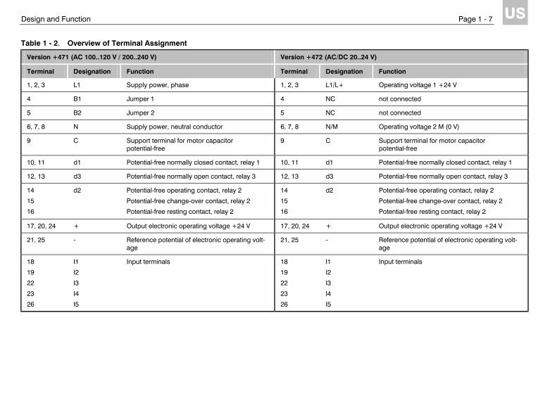
Table 1 - 2. Overview of Terminal Assignment
Version +471 (AC 100..120 V / 200..240 V) Version +472 (AC/DC 20..24 V)
Terminal Designation Function Terminal Designation Function
1, 2, 3 L1 Supply power, phase 1, 2, 3 L1/L+ Operating voltage 1 +24 V
4 B1 Jumper 1 4 NC not connected
5 B2 Jumper 2 5 NC not connected
6, 7, 8 N Supply power, neutral conductor 6, 7, 8 N/M Operating voltage 2 M (0 V)
9 C Support terminal for motor capacitor potential-free
9 C Support terminal for motor capacitor potential-free
10, 11 d1 Potential-free normally closed contact, relay 1 10, 11 d1 Potential-free normally closed contact, relay 1
12, 13 d3 Potential-free normally open contact, relay 3 12, 13 d3 Potential-free normally open contact, relay 3
14
15
16
d2 Potential-free operating contact, relay 2
Potential-free change-over contact, relay 2
Potential-free resting contact, relay 2
14
15
16
d2 Potential-free operating contact, relay 2
Potential-free change-over contact, relay 2
Potential-free resting contact, relay 2
17, 20, 24 + Output electronic operating voltage +24 V 17, 20, 24 + Output electronic operating voltage +24 V
21, 25 - Reference potential of electronic operating volt-age
21, 25 - Reference potential of electronic operating volt-age
18
19
22
23
26
I1
I2
I3
I4
I5
Input terminals 18
19
22
23
26
I1
I2
I3
I4
I5
Input terminals
Design and Function Page 1 - 8
US
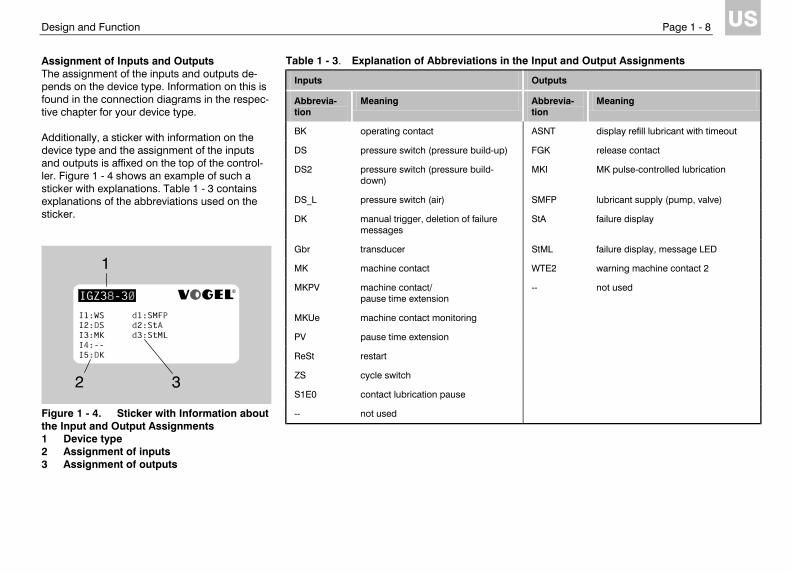
Assignment of Inputs and Outputs The assignment of the inputs and outputs de-pends on the device type. Information on this is found in the connection diagrams in the respec-tive chapter for your device type. Additionally, a sticker with information on the device type and the assignment of the inputs and outputs is affixed on the top of the control-ler. Figure 1 - 4 shows an example of such a sticker with explanations. Table 1 - 3 contains explanations of the abbreviations used on the sticker.
Figure 1 - 4. Sticker with Information about the Input and Output Assignments 1 Device type 2 Assignment of inputs 3 Assignment of outputs
Table 1 - 3. Explanation of Abbreviations in the Input and Output Assignments
Inputs Outputs
Abbrevia-tion
Meaning Abbrevia-tion
Meaning
BK operating contact ASNT display refill lubricant with timeout
DS pressure switch (pressure build-up) FGK release contact
DS2 pressure switch (pressure build-down)
MKI MK pulse-controlled lubrication
DS_L pressure switch (air) SMFP lubricant supply (pump, valve)
DK manual trigger, deletion of failure messages
StA failure display
Gbr transducer StML failure display, message LED
MK machine contact WTE2 warning machine contact 2
MKPV machine contact/ pause time extension
-- not used
MKUe machine contact monitoring
PV pause time extension
ReSt restart
ZS cycle switch
S1E0 contact lubrication pause
-- not used
Installation Page 1 - 9
US
Installation
The controller may only be installed by trained specialists who are capable of recognizing the hazards in connection with touching life components.
The controller may only be adjusted by trained specialists.
Since the controller version I is supplied as an integral part of a compact system, only the in-stallation of the version E of the controller is de-scribed in the following. First check in which operating voltage range the unit is to be operated. For operation on 100 – 120 V AC the two jumpers supplied must be used to connect L1 to B1 and B2 to N. Fasten the controller to the assembly rail in the control cabinet and connect the inputs and out-puts according to the connection diagram of the device type. The connection diagrams are found in the individual chapters for the device types. To be able to enter control parameters such as operating mode or pause time via the operating display, the unit must be connected to power. Input of parameters is described in the following chapter.
Note that the universal controller must be connected to power before you can change parameters.
Power must be switched on or off in-stantaneously.
When power is applied, the unit starts a func-tional sequence depending on the device type. Notes on this sequence are contained in the chapters on the individual device types. Check the function of the unit on the basis of the status messages appearing on the display.
Operation Page 1 - 10
US
Operation
The universal controller, version I, in-stalled in the compact system must only be operated by trained special-ists, who are capable of recognizing the hazards in connection with touch-ing life components, unless the con-troller has a separate power supply that has been installed by a trained specialist for the purpose of pro-gramming, while all other components that could be touched are discon-nected from power.
Display Structure
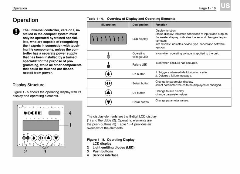
Figure 1 - 5 shows the operating display with its display and operating elements.
The display elements are the 8-digit LCD display (1) and the LEDs (2). Operating elements are the push-buttons (3). Table 1 - 4 provides an overview of the elements. Figure 1 - 5. Operating Display 1 LCD display 2 Light emitting diodes (LED) 3 Push buttons 4 Service interface
Table 1 - 4. Overview of Display and Operating Elements
Illustration Designation Function
LCD display
Display function Status display: indicates conditions of inputs and outputs. Parameter display: indicates the set and changeable pa-rameters. Info display: indicates device type loaded and software version.
Operating voltage LED
Is on when operating voltage is applied to the unit.
Failure LED Is on when a failure has occurred.
DK button 1. Triggers intermediate lubrication cycle.
2. Deletes a failure message.
Select button Change to parameter display,
select parameter values to be displayed or changed.
Up button Change to info display,
change parameter values.
Down button Change parameter values.
Operation Page 1 - 11
US
LEDs
If the green LED is on, operating voltage is pre-sent. If the red LED is on, this generally indicates an error situation. LCD Display
The 8-digit LCD display serves several display functions: Status display: Indicates conditions of inputs and outputs. Info display: Indicates device type loaded and software ver-sion. Display of input functions: In most device types, the functions of the inputs (normally open contact or normally closed con-tact) can be set here. Parameter display: Indicates the set and changeable parameters. The basic display function is the status display. From it, the parameter display or info display can be called up.
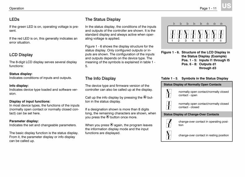
The Status Display
In the status display, the conditions of the inputs and outputs of the controller are shown. It is the standard display and always active when oper-ating voltage is applied. Figure 1 - 6 shows the display structure for the status display. Only configured outputs or in-puts are shown. The configuration of the inputs and outputs depends on the device type. The meaning of the symbols is explained in table 1 - 5. The Info Display
The device type and firmware version of the controller can also be called up at the display. Call up the info display by pressing the but-ton in the status display. If a designation shown is more than 8 digits long, the remaining characters are shown, when you press the button once more. When you press again, the program leaves the information display mode and the input functions are displayed.
Figure 1 - 6. Structure of the LCD Display in
the Status Display (Example) Pos. 1 - 5: Inputs I1 through I5 Pos. 6 - 8: Outputs d1 through d3
Table 1 - 5. Symbols in the Status Display
Status Display of Normally Open Contacts
normally open contact/normally closed contact - open
normally open contact/normally closed contact - closed
Status Display of Change-Over Contacts
change-over contact in operating posi-tion
change-over contact in resting position
Operation Page 1 - 12
US
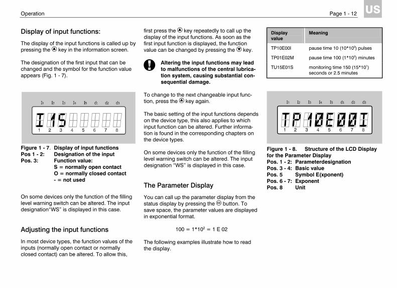
Display of input functions:
The display of the input functions is called up by pressing the key in the information screen. The designation of the first input that can be changed and the symbol for the function value appears (Fig. 1 - 7).
Figure 1 - 7. Display of input functions Pos 1 - 2: Designation of the input Pos. 3: Function value: S = normally open contact O = normally closed contact - = not used
On some devices only the function of the filling level warning switch can be altered. The input designation“WS” is displayed in this case. Adjusting the input functions
In most device types, the function values of the inputs (normally open contact or normally closed contact) can be altered. To allow this,
first press the key repeatedly to call up the display of the input functions. As soon as the first input function is displayed, the function value can be changed by pressing the key.
Altering the input functions may lead to malfunctions of the central lubrica-tion system, causing substantial con-sequential damage.
To change to the next changeable input func-tion, press the key again. The basic setting of the input functions depends on the device type, this also applies to which input function can be altered. Further informa-tion is found in the corresponding chapters on the device types. On some devices only the function of the filling level warning switch can be altered. The input designation “WS” is displayed in this case. The Parameter Display
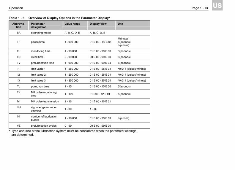
You can call up the parameter display from the status display by pressing the button. To save space, the parameter values are displayed in exponential format.
100 = 1*102 = 1 E 02 The following examples illustrate how to read the display.
Display value
Meaning
TP10E00I pause time 10 (10*100) pulses
TP01E02M pause time 100 (1*102) minutes
TU15E01S monitoring time 150 (15*101) seconds or 2.5 minutes
Figure 1 - 8. Structure of the LCD Display for the Parameter Display Pos. 1 - 2: Parameterdesignation Pos. 3 - 4: Basic value Pos. 5 Symbol E(xponent) Pos. 6 - 7: Exponent Pos. 8 Unit
Operation Page 1 - 13
US
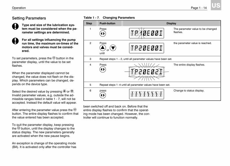
Table 1 - 6. Overview of Display Options in the Parameter Display*
Abbrevia-tion
Parameter designation
Value range Display View Unit
BA operating mode A, B, C, D, E A, B, C, D, E
TP pause time 1 - 990 000 01 E 00 – 99 E 04 M(inutes) S(econds) I (pulses)
TU monitoring time 1 - 99 000 01 E 00 - 99 E 03 S(econds)
TN dwell time 0 - 99 000 00 E 00 - 99 E 03 S(econds)
TV prelubrication time 1 - 990 000 01 E 00 - 99 E 04 S(econds)
I1 limit value 1 1 - 250 000 01 E 00 - 25 E 04 *0,01 I (pulses/minute)
I2 limit value 2 1 - 250 000 01 E 00 - 25 E 04 *0,01 I (pulses/minute)
I3 limit value 3 1 - 250 000 01 E 00 - 25 E 04 *0,01 I (pulses/minute)
TL pump run time 1 - 15 01 E 00 - 15 E 00 S(econds)
TK MK pulse monitoring time 1 - 120 01 E00 - 12 E 01 S(econds)
MI MK pulse transmission 1 - 25 01 E 00 - 25 E 01
NH signal edge (number strokes) 1 - 30 1 – 30
NI number of lubrication pulses 1 - 99 000 01 E 00 - 99 E 03 I (pulses)
VZ prelubrication cycles 0 - 99 00 E 00 - 99 E 00
* Type and size of the lubrication system must be considered when the parameter settings are determined.
Operation Page 1 - 14
US
Setting Parameters
Type and size of the lubrication sys-tem must be considered when the pa-rameter settings are determined.
For all settings influencing the pump run time, the maximum on-times of the motors and valves must be consid-ered.
To set parameters, press the button in the parameter display, until the value to be set flashes. When the parameter displayed cannot be changed, the value does not flash on the dis-play. Which parameters can be changed, de-pends on the device type. Select the desired value by pressing or . Invalid parameter values, e.g. outside the ad-missible ranges listed in table 1 - 7, will not be accepted. Instead the default value will appear. After entering the parameter value press the button. The entire display flashes to confirm that the value entered has been accepted. To quit the parameter display, keep pressing the button, until the display changes to the status display. The new parameters generally are activated when the new pause begins. An exception is change of the operating mode (BA). It is activated only after the controller has
been switched off and back on. Before that the entire display flashes to confirm that the operat-ing mode has been changed. However, the con-troller will continue to function normally.
Table 1 - 7. Changing Parameters
Step Push-button Display
1 Press
The parameter value to be changed flashes.
2 Press
or until
the parameter value is reached.
3 Repeat steps 1 – 2, until all parameter values have been set.
4 Press
The entire display flashes.
5 Repeat steps 1 -4 until all parameter values have been set.
6 press
Change to status display.
Use as Replacement Page 1 - 15
US
Use as Replacement
The controller may only be replaced by trained specialists who are capable of recognizing the hazards in connec-tion with touching life components.
The controller may only be adjusted by trained specialists.
If you wish to replace an existing controller with a universal controller, please observe the follow-ing notes.
Before replacing the unit, check if the local supply voltage agrees with the voltage indicated on the new control-ler.
Note the parameter values adjusted in the old controller. Which values must be noted, de-pends on the device type; please turn to the re-spective device type description. If necessary, label all wires to be disconnected and recon-nected to the new unit, such as WS, DS, DS2, MK, DK , +, - etc.; on the wires to be connected to the relays d1, d2 and d3, also note the re-spective terminal numbers.
Now remove the old controller and replace it with the universal controller. Connect the inputs and outputs according to their previous func-tions. The assignment of inputs and outputs is indicated on the sticker on top of the device or is listed in the chapter on the respective device type. Ensure that you have correctly adjusted the op-erating voltage as described in the chapter As-sembly; then only connect the unit to power.
Power must be switched on or off in-stantaneously.
Subsequently adjust the parameter values noted from the old controller at the keypad of the universal controller.
Note that the universal controller must be connected to power before you can change parameters.
Check the function of the unit on the basis of the status messages appearing on the display.
Failures Page 1 - 16
US
Failures
Failure Messages
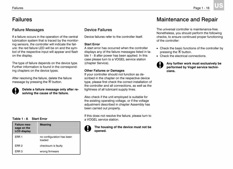
If a failure occurs in the operation of the central lubrication system that is traced by the monitor-ing sensors, the controller will indicate the fail-ure: the red failure LED will be on and the sym-bol of the respective input will appear and flash on the display. The type of failure depends on the device type. Further information is found in the correspond-ing chapters on the device types. After resolving the failure, delete the failure message by pressing the button.
Delete a failure message only after re-solving the cause of the failure.
Device Failures
Device failures refer to the controller itself. Start Error A start error has occurred when the controller displays any of the failure messages listed in ta-ble 1 - 8 after power has been applied. In this case please turn to a VOGEL service station (chapter Service). Other Failures or Damages If your controller should not function as de-scribed in the chapter on the respective device type, please first check the correct installation of the controller and all connections, as well as the tightness of all lubricant supply lines. Also check if the unit employed is suitable for the existing operating voltage, or if the voltage adjustment described in chapter Assembly has been carried out properly. If this does not resolve the failure, please turn to a VOGEL service station.
The housing of the device must not be opened.
Maintenance and Repair
The universal controller is maintenance-free. Nonetheless, you should perform the following checks, to ensure continued proper functioning of the controller: • Check the basic functions of the controller by
pressing the button. • Check the electrical connections.
Any further work must exclusively be performed by Vogel service techni-cians.
Table 1 - 8. Start Error
Failure mes-sage on the LCD display
Meaning
ERR 1 no configuration has been loaded
ERR 2 checksum is faulty
ERR 3 wrong firmware

Specifications Page 1 - 17
US
Specifications
Version +471 Version +472
Rated input voltage Un AC (100..120) V or AC (200..240) V
DC 20..24 V or AC 20..24 V
Input voltage range 0.85 Un to 1.1 Un (85..132 V / 170..264 V)
0.85 Un to 1.1 Un (17..26.4 V)
Rated input current 70 mA / 35 mA 75 mA, at maximum output load: 250 mA
Power consumption 8 W 5 W
Rated frequency 50..60 Hz DC or 50..60 Hz
Frequency range 49..61 Hz DC or 49..61 Hz
Disengaging value max. 10 % of Un max. 10 % of Un
Reclosing time 1 s 1 s
Residual ripple of input voltage
not relevant DC: max. 5 %
Max. fusing 6.3 A 6.3 A
Max. switching current 5 A AC 5 A AC
Max. relay switching voltage
250 V AC 250 V AC
Overvoltage category to DIN VDE 0110
III III
Rated voltage of inputs 24 V DC 24 V DC
Input impedance 2.4 kΩ +/-10 % 2.4 kΩ +/-10 %
Input level, low 0 V..+4 V 0 V..+4 V
Input level, high +10 V..+24 V +10 V..+24 V
Coincidence factor for inputs
max. 0.8 max. 0.8
Versions +471 and +472
Output voltge for inputs and external consumers
24 V DC +10% / -15%
Rated output current (outputs „+“) included for external consumers
110 mA max. 60 mA
MK input
max. input frequency pulse duty factor
30 Hz 1:1
Conductors connected (flexible)
with terminal sleeves with Twin terminal sleeves length on which to remove insulation
max. 2.5 mm2 or 2*0.75 mm2 max. 2*1.5 mm2 8 mm
Enclosure type (Version E) IP30, terminals IP20
Protection class (Version E) II
Rated isolation voltage 250 V AC
Contamination class 2
Operating temperature storage temperature
0 °C to 60 °C -25 °C to 70 °C
Dimensions W x H x D (Version E) approx. 70 mm x 75 mm x 110 mm
Voltage capacity to EN 61131-2 and EN 50178
supply voltage / relay contacts supply voltage / electronics relay contacts / electronics
1780 V 2830 V 2830 V
EMC
noice resistance noice emission
EN 61000-6-2 EN 500081-1
Vibration resistance to EN 60068-2-6 Shock resistance to EN 600068-2-27
10 – 57 Hz; 0.075 mm (amplitude) 15 g; 11 ms (half-sine)
Controllers for Oil+Air Lubrication System Page 2 - 27
US
Controllers for Oil+Air Lu-brication System
Application
The controllers described in this chapter are used for time or pulse-control of oil+air lubrica-tion systems. Overview
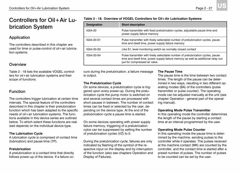
Table 2 - 18 lists the available VOGEL control-lers for oil+air lubrication systems and their scope of functions. Function
The controllers trigger lubrication at certain time intervals. The special feature of the controllers described in this chapter is their prelubrication function which has been adapted to the specific needs of oil+air lubrication systems. The func-tions available in this device series are outlined below. To which extent these functions are real-ized depends on the individual device type. The Lubrication Cycle A lubrication cycle is comprised of contact time (lubrication) and pause time (TP). Prelubrication A prelubrication is a contact time that directly follows power-up of the device. If a failure oc-
curs during the prelubrication, a failure message is output. The Prelubrication Cycle On some devices, a prelubrication cycle is trig-gered upon every power-up. During the prelu-brication cycle the pump motor is switched on and several contact times are processed with short pauses in between. The number of contact times can be fixed or selected by the user, de-pending on the device type. At the end of the prelubrication cycle a pause time is started. On some devices operating with power supply failure memory, triggering of a prelubrication cylce can be suppressed by setting the number of prelubrication cycles (VZ) to 0. During the prelubrication cycle, failures are only indicated by flashing of the symbol of the re-spective input on the display and by interruption of the function (also see chapters Operation and Display of Failures).
The Pause Time The pause time is the time between two contact times. The length of the pause can be deter-mined in two ways, resulting in two different op-erating modes (BA) of the controllers (pulse transmitter or pulse counter). The operating mode can be adjusted manually at the unit (see chapter Operation - general part of the operat-ing manual). Operating Mode Pulse Transmitter In this operating mode the controller determines the length of the pause by starting a contact time at an interval programmed by the user. Operating Mode Pulse Counter In this operating mode the pause time is deter-mined by the machine, sending pulses to the controller while it operates. The pulses received at the machine contact (MK) are counted by the controller, and the contact time is started after a preset number of pulses. The number of pulses to be counted can be set by the user.
Table 2 - 18. Overview of VOGEL Controllers for Oil+Air Lubrication Systems
Designation Short description
IG54-20 Pulse transmitter with fixed prelubrication cycles, adjustable pause time and power supply failure memory
IG54-20-S1 Pulse transmitter with freely selectable number of prelubrication cycles, pause time and dwell time, power supply failure memory
IG54-20-S3 Like S1, level monitoring switch as normally closed contact
IG54-20-S4 Pulse transmitter with freely selectable number of prelubrication cycles, pause time and dwell time, power supply failure memory as well as additional relay out-put for compressed air valve
Controllers for Oil+Air Lubrication System Page 2 - 28
US
The Contact Time After time-out of the pause time, the controller triggers the lubrication, also referred to as con-tact time. The contact time is comprised of monitoring time (TU) and pump dwell time (TN). Pressure Build-Up Monitoring Oil Pressure During the contact time, the pump motor is first started and the pressure required for lubrication is built up in the lubrication lines. This process is monitored by a pressure switch (DS). The re-quired pressure must be reached within a cer-tain time, the monitoring time, otherwise the pump is switched off and a failure message is output. Monitoring Time TU The monitoring time is a time window for pres-sure build-up by the pump. If the required pres-sure is reached within the monitoring time, the latter is terminated. Thereafter the pump dwell time is started. The monitoring time is generally adjusted permanently and cannot be changed by the user. Pump Dwell Time The pump dwell time is the time during which the pump continues running after the required pressure has been built up in the lubrication lines, to ensure all lubrication points are sup-plied with lubricant even in very large central lu-brication systems. Pump Run Time Limit The pump run time (TL) is limited in principle by the monitoring time.
Air Pressure Monitoring With an additional pressure switch (DS_L) the air pressure in the compressed air line is moni-tored. If the pressure drops or if no pressure is built up in the first place, a failure messsage is output and the function sequence stopped. Level Monitoring The filling level of the lubricant reservoir is moni-tored by means of a level monitoring switch (WS). This switch can be configured as a nor-mally closed contact or normally open contact; this must be considered when the device type is selected. If the level monitoring switch is config-ured as a normally closed contact, the signal lines leading up to the level monitoring switch are at the same time monitored for breakage of the wires. As soon as the level in the lubricant reservoir drops below minimum, the function of the lubri-cation system is stopped and a failure message output. Automatic Lubricant Refill To some of the controllers two level monitoring switches (WS_L and WS_H) can be connected to allow control of automatic lubricant refill. If the lubricant level in the lubricant reservoir drops below the minimum, the relay d3 activates a valve or pump refilling lubricant until the maxi-mum level is reached. If automatic lubricant refill fails, that is, if the level remains below the mini-mum level for a prolonged period, a failure mes-sage is output.
Power Supply Failure Memory (EEPROM) In case the power supply fails, the power supply failure memory saves the most important data of the controller, such as remaining pause time and a failure message. This allows the controller to continue the function on the basis of the de-vice type upon the next power-up, and failure messages are not lost. Installation
Install the controller in the control cabinet for a VOGEL central lubrication system as described in chapter Assembly in the general section of this operating manual. Also please observe the notes in the description of the respective device type. Operation
Switching On The device is switched on, when the operating voltage is applied. When the operating voltage is present, the green operating voltage LED is on.
Power must be switched on or off in-stantaneously.
Upon power-up the device begins the function sequence, generally it starts with a prelubrica-tion cycle.
Controllers for Oil+Air Lubrication System Page 2 - 29
US
Prelubrication On some devices prelubrication is started upon power-up. The pump motor is switched on and the failure message relay d2 is energised. Pre-lubrication is performed just like a standard con-tact time. Prelubrication Cycle On some devices a prelubrication cycle is started upon power-up. The pump motor is switched on and a number of lubrication runs is started with fixed pause times in between. Dur-ing this time relay d2 remains de-energised and the failure LED is on, however, this does not in-dicate a failure. At the end of the prelubrication cycle, a pause time is started, relay d2 is energised and the failure LED shuts off. If a failure occurs during the prelubrication cy-cle, relay d2 remains de-energised and the fail-ure LED is still on (also see chapter Display of Failures). Pause Time After time-out of the prelubrication, relay d1 is de-energised and the pump motor shut off. Then the preset value for the pause time is read and the pause started. Subsequently contact time and pause time alternate. Contact Time (Lubrication) The contact time is started after time-out of the pause time. It is comprised of the time required for pressure build-up and the dwell time. At the
beginning of the contact time, relay d1 is ener-gised and the pump motor thereby switched on. As soon as the required pressure is reached, the monitoring time is terminated and the pump dwell time started. At the end of the dwell time, the next pause time begins. Relay d2 in Normal Operation When the operating voltage is applied and the device is operating without failures, relay d2 is always energised, except during the prelubrica-tion cycle. Intermediate Lubrication Short pressing of the button during a pause triggers an intermediate lubrication. Intermedi-ate lubrication is performed just like a standard contact time. Switching Off The device is switched off by separating it from the operating power supply.
Upon shut-off, the device must remain off for some time, before it can be switched on again (see reclosing time, specifications).
Changing Parameters and Operating Mode The change of parameters and the selection of the operating mode are described in chapter Operation in the general part of this operating manual. Parameter changes, such as change of the pause time, will become operative with the beginning of the next pause. A change of the
operating mode will only become operative after the device is switched off and back on. Operation with Power Supply Failure Memory In case the power supply fails, the power supply failure memory saves the most important data of the controller, such as remaining pause time and a failure message. After a power failure, the device generally starts with a prelubrication cycle. If this function has been deactivated, however, the start after return of power depends on the situation prevailing when the power failure occurred (see table 2 - 19). Display of Failures
If a failure occurs, the red failure LED is on and the symbol for the respective input flashes on the display. Oil Pressure Missing If the pressure required is not built up in the main supply line during the monitoring time, that is, if the pressure switch DS is not activated, the failure LED will switch on and the pump motor will shut off. At the same time the symbol for in-put DS will flash on the display. The relays d1 and d2 are or remain de-energised. At the same time the function sequence is stopped. Air Pressure Missing An air pressure failure is present when the pres-sure switch DS2 is not activated during the
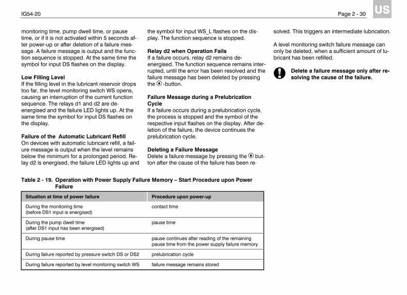
IG54-20 Page 2 - 30
US
monitoring time, pump dwell time, or pause time, or if it is not activated within 5 seconds af-ter power-up or after deletion of a failure mes-sage. A failure message is output and the func-tion sequence is stopped. At the same time the symbol for input DS flashes on the display. Low Filling Level If the filling level in the lubricant reservoir drops too far, the level monitoring switch WS opens, causing an interruption of the current function sequence. The relays d1 and d2 are de-energised and the failure LED lights up. At the same time the symbol for input DS flashes on the display. Failure of the Automatic Lubricant Refill On devices with automatic lubricant refill, a fail-ure message is output when the level remains below the minimum for a prolonged period. Re-lay d2 is energised, the failure LED lights up and
the symbol for input WS_L flashes on the dis-play. The function sequence is stopped. Relay d2 when Operation Fails If a failure occurs, relay d2 remains de-energised. The function sequence remains inter-rupted, until the error has been resolved and the failure message has been deleted by pressing the -button. Failure Message during a Prelubrication Cycle If a failure occurs during a prelubrication cycle, the process is stopped and the symbol of the respective input flashes on the display. After de-letion of the failure, the device continues the prelubrication cycle. Deleting a Failure Message Delete a failure message by pressing the but-ton after the cause of the failure has been re-
solved. This triggers an intermediate lubrication. A level monitoring switch failure message can only be deleted, when a sufficient amount of lu-bricant has been refilled.
Delete a failure message only after re-solving the cause of the failure.
Table 2 - 19. Operation with Power Supply Failure Memory – Start Procedure upon Power Failure
Situation at time of power failure Procedure upon power-up
During the monitoring time (before DS1 input is energised)
contact time
During the pump dwell time (after DS1 input has been energised)
pause time
During pause time pause continues after reading of the remaining pause time from the power supply failure memory
During failure reported by pressure switch DS or DS2 prelubrication cycle
During failure reported by level monitoring switch WS failure message remains stored
IG54-20 Page 2 - 31
US
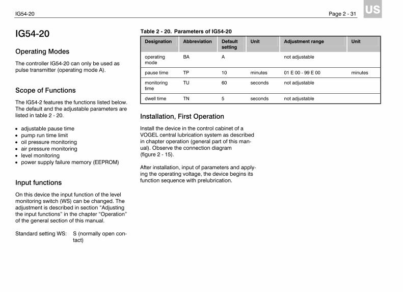
IG54-20
Operating Modes
The controller IG54-20 can only be used as pulse transmitter (operating mode A). Scope of Functions
The IG54-2 features the functions listed below. The default and the adjustable parameters are listed in table 2 - 20. • adjustable pause time • pump run time limit • oil pressure monitoring • air pressure monitoring • level monitoring • power supply failure memory (EEPROM) Input functions
On this device the input function of the level monitoring switch (WS) can be changed. The adjustment is described in section “Adjusting the input functions” in the chapter “Operation” of the general section of this manual. Standard setting WS: S (normally open con-
tact)
Installation, First Operation
Install the device in the control cabinet of a VOGEL central lubrication system as described in chapter operation (general part of this man-ual). Observe the connection diagram (figure 2 - 15). After installation, input of parameters and apply-ing the operating voltage, the device begins its function sequence with prelubrication.
Table 2 - 20. Parameters of IG54-20
Designation Abbreviation Default setting
Unit Adjustment range Unit
operating mode
BA A not adjustable
pause time TP 10 minutes 01 E 00 - 99 E 00 minutes
monitoring time
TU 60 seconds not adjustable
dwell time TN 5 seconds not adjustable
IG54-20 Page 2 - 32
US
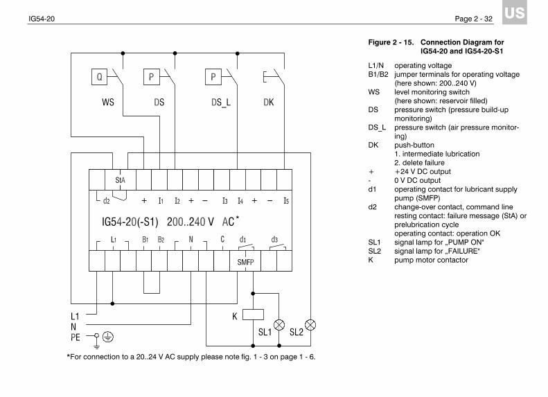
Figure 2 - 15. Connection Diagram for IG54-20 and IG54-20-S1
L1/N operating voltage B1/B2 jumper terminals for operating voltage
(here shown: 200..240 V) WS level monitoring switch
(here shown: reservoir filled) DS pressure switch (pressure build-up
monitoring) DS_L pressure switch (air pressure monitor-
ing) DK push-button
1. intermediate lubrication 2. delete failure
+ +24 V DC output - 0 V DC output d1 operating contact for lubricant supply
pump (SMFP) d2 change-over contact, command line
resting contact: failure message (StA) or prelubrication cycle operating contact: operation OK
SL1 signal lamp for „PUMP ON" SL2 signal lamp for „FAILURE" K pump motor contactor
*
*For connection to a 20..24 V AC supply please note fig. 1 - 3 on page 1 - 6.
IG54-20 Page 2 - 33
US
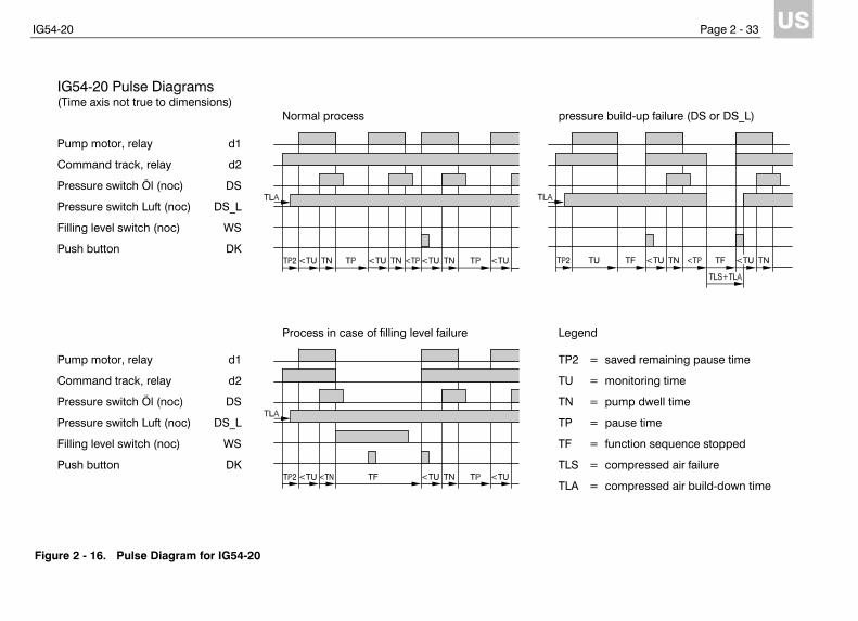
Figure 2 - 16. Pulse Diagram for IG54-20
IG54-20 Pulse Diagrams (Time axis not true to dimensions) Normal process pressure build-up failure (DS or DS_L) Pump motor, relay d1
Command track, relay d2
Pressure switch Öl (noc) DS
Pressure switch Luft (noc) DS_L
Filling level switch (noc) WS
Push button DK
Process in case of filling level failure Legend
Pump motor, relay d1 TP2 = saved remaining pause time
Command track, relay d2 TU = monitoring time
Pressure switch Öl (noc) DS TN = pump dwell time
Pressure switch Luft (noc) DS_L TP = pause time
Filling level switch (noc) WS TF = function sequence stopped
Push button DK TLS = compressed air failure
TLA = compressed air build-down time
IG54-20-S1, IG54-20-S3, IG54-20-S4 Page 2 - 34
US
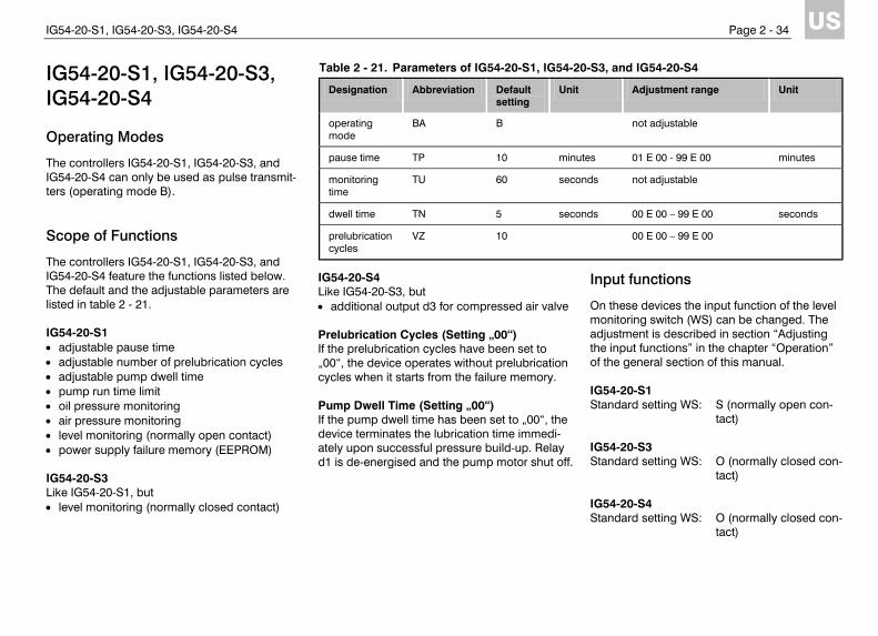
IG54-20-S1, IG54-20-S3, IG54-20-S4
Operating Modes
The controllers IG54-20-S1, IG54-20-S3, and IG54-20-S4 can only be used as pulse transmit-ters (operating mode B). Scope of Functions
The controllers IG54-20-S1, IG54-20-S3, and IG54-20-S4 feature the functions listed below. The default and the adjustable parameters are listed in table 2 - 21. IG54-20-S1 • adjustable pause time • adjustable number of prelubrication cycles • adjustable pump dwell time • pump run time limit • oil pressure monitoring • air pressure monitoring • level monitoring (normally open contact) • power supply failure memory (EEPROM) IG54-20-S3 Like IG54-20-S1, but • level monitoring (normally closed contact)
IG54-20-S4 Like IG54-20-S3, but • additional output d3 for compressed air valve Prelubrication Cycles (Setting „00“) If the prelubrication cycles have been set to „00“, the device operates without prelubrication cycles when it starts from the failure memory. Pump Dwell Time (Setting „00“) If the pump dwell time has been set to „00“, the device terminates the lubrication time immedi-ately upon successful pressure build-up. Relay d1 is de-energised and the pump motor shut off.
Input functions
On these devices the input function of the level monitoring switch (WS) can be changed. The adjustment is described in section “Adjusting the input functions” in the chapter “Operation” of the general section of this manual. IG54-20-S1 Standard setting WS: S (normally open con-
tact) IG54-20-S3 Standard setting WS: O (normally closed con-
tact) IG54-20-S4 Standard setting WS: O (normally closed con-
tact)
Table 2 - 21. Parameters of IG54-20-S1, IG54-20-S3, and IG54-20-S4
Designation Abbreviation Default setting
Unit Adjustment range Unit
operating mode
BA B not adjustable
pause time TP 10 minutes 01 E 00 - 99 E 00 minutes
monitoring time
TU 60 seconds not adjustable
dwell time TN 5 seconds 00 E 00 – 99 E 00 seconds
prelubrication cycles
VZ 10 00 E 00 – 99 E 00
IG54-20-S1, IG54-20-S3, IG54-20-S4 Page 2 - 35
US
Installation, First Operation
Install the device in the control cabinet of a VOGEL central lubrication system as described in chapter operation (general part of this man-ual). Observe the connection diagram (figure 2 - 17). After installation, input of parameters and apply-ing the operating voltage, the device begins its function sequence with prelubrication.
IG54-20-S1, IG54-20-S3, IG54-20-S4 Page 2 - 36
US
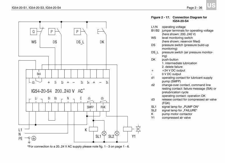
Figure 2 - 17. Connection Diagram for IG54-20-S4
L1/N operating voltage B1/B2 jumper terminals for operating voltage
(here shown: 200..240 V) WS level monitoring switch
(here shown: reservoir filled) DS pressure switch (pressure build-up
monitoring) DS_L pressure switch (air pressure monitor-
ing) DK push-button
1. intermediate lubrication 2. delete failure
+ +24 V DC output - 0 V DC output d1 operating contact for lubricant supply
pump (SMFP) d2 change-over contact, command line
resting contact: failure message (StA) or prelubrication cycle operating contact: operation OK
d3 release contact for compressed air valve (FGK)
SL1 signal lamp for „PUMP ON" SL2 signal lamp for „FAILURE" K pump motor contactor Y1 compressed air valve
*
*For connection to a 20..24 V AC supply please note fig. 1 - 3 on page 1 - 6.

IG54-20-S1, IG54-20-S3, IG54-20-S4 Page 2 - 37
US
Figure 2 - 18. Pulse Diagram for IG54-20-S4
IG54-20 -S4 Pulse Diagrams (Time axis not true to dimensions, Darstellung nach Ablauf der Vorschmierzyklen)
Normal process pressure build-up failure (DS or DS_L) Pump motor, relay d1
Command track, relay d2
Release relay d3
Pressure switch Öl (noc) DS
Pressure switch Luft (noc) DS_L
Filling level switch (ncc) WS
Push button DK
Process in case of filling level failure Legend
Pump motor, relay d1 TPV = last pause in prelubrication cycle
Command track, relay d2 TU = monitoring time
Release relay d3 TN = pump dwell time
Pressure switch Öl (noc) DS TP = pause time
Pressure switch Luft (noc) DS_L TF = function sequence stopped
Filling level switch (ncc) WS TLS = compressed air failure
Push button DK TLA = compressed air build-down time