Embed Size (px)
Citation preview

R
OWNER & INSTALLATION MANUALA f f i n i t y 3 0 G e
C o o k t o p
Evo, Inc., 20560 SW 115th Ave., Tualatin, OR 97062 USAPhone 503.626.1802 | Fax 503.213.5869 | www.evoamerica.com | [email protected]
Evo Affi nity 30GeElectronically-Controlled Gas Cooktop
For Indoor Use Only
Certifi cation: ANSI Z83.11b-2009/CSA 1.8B-2009. OMNI Report # 0141GM004SPart #: Commercial models: 10-0050-NG | 10-0050-LPResidential models: 10-0051-NG | 10-0051-LP Doc: OM-C&R-30Ge 01/2016Copyright © 2017
This appliance and its individual shutoff valve must be disconnected from the gas supply piping system during any pressure testing of system at test pressures in excess of 1/2 PSI (3.5kPa).
This appliance must be isolated from the gas supply piping system by closing its individual manual shutoff valve during any pressures testing of the gas supply system at test pressures equal to or less than 1/2 PSI (3.5kPa).
This appliance, when installed, must be electrically grounded in accordance with local codes,or in the absence of local codes, with the National Electrical Code, ANSI/NFPA70,
or the Canadian Electrical Code, CSA C22.2, as applicable.
Cleaning Instructions
evoamerica.com
FINAL QR Code for Evo Cleaning.indd 1 11/19/2015 11:43:18 AM
INSTALLATION INSTRUCTIONSA f f i n i t y 3 0 G e
Evo, Inc., 20560 SW 115th Ave., Tualatin, OR 97062 USAPhone 503.626.1802 | Fax 503.213.5869 | www.evoamerica.com | [email protected] 1
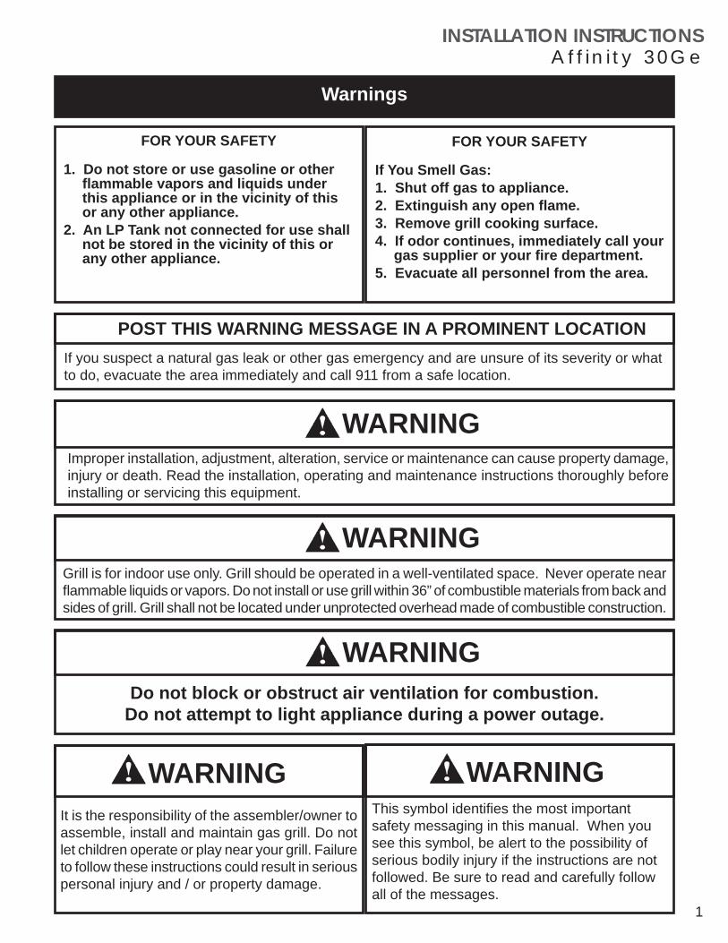
Grill is for indoor use only. Grill should be operated in a well-ventilated space. Never operate near fl ammable liquids or vapors. Do not install or use grill within 36” of combustible materials from back and sides of grill. Grill shall not be located under unprotected overhead made of combustible construction.
Warnings
FOR YOUR SAFETY
If You Smell Gas:1. Shut off gas to appliance.2. Extinguish any open fl ame.3. Remove grill cooking surface.4. If odor continues, immediately call your
gas supplier or your fi re department.5. Evacuate all personnel from the area.
FOR YOUR SAFETY
1. Do not store or use gasoline or other fl ammable vapors and liquids under this appliance or in the vicinity of this or any other appliance.
2. An LP Tank not connected for use shall not be stored in the vicinity of this or any other appliance.
Improper installation, adjustment, alteration, service or maintenance can cause property damage, injury or death. Read the installation, operating and maintenance instructions thoroughly before installing or servicing this equipment.
If you suspect a natural gas leak or other gas emergency and are unsure of its severity or what to do, evacuate the area immediately and call 911 from a safe location.
POST THIS WARNING MESSAGE IN A PROMINENT LOCATION
Do not block or obstruct air ventilation for combustion.
WARNING
WARNINGThis symbol identifi es the most important safety messaging in this manual. When you see this symbol, be alert to the possibility of serious bodily injury if the instructions are not followed. Be sure to read and carefully follow all of the messages.
It is the responsibility of the assembler/owner to assemble, install and maintain gas grill. Do not let children operate or play near your grill. Failure to follow these instructions could result in serious personal injury and / or property damage.
WARNING
Do not attempt to light appliance during a power outage.
WARNING
WARNING

INSTALLATION INSTRUCTIONSA f f i n i t y 3 0 G e
Evo, Inc., 20560 SW 115th Ave., Tualatin, OR 97062 USAPhone 503.626.1802 | Fax 503.213.5869 | www.evoamerica.com | [email protected]
THIS MANUAL MUST BE RETAINED FOR FUTURE REFERENCE. READ, UNDERSTAND, AND FOLLOW THE INSTRUCTIONS AND WARNINGS CONTAINED IN THIS MANUAL.
DANGER POTENTIALLY HAZARDOUS SITUATION WHICH, IF NOT AVOIDED, COULD RESULT IN DEATH HIGH
VOLTAGE
CAUTION POTENTIALLY HAZARDOUS SITUATION WHICH, IF NOT AVOIDED, MAY RESULT IN MINOR OR MODERATE INJURY.
WARNING POTENTIALLY HAZARDOUS SITUATION WHICH, IF NOT AVOIDED, COULD RESULT IN DEATH OR SERIOUS INJURY
CAUTION Helpful tips and technique instructions are shown.
Notes
Complete Now For Future Reference
Model #_______________________________ Serial # _________________________________
Date Purchased ________________________ Location Purchased _______________________
Date Installed __________________________ Location Installed _________________________
The installation of this cooking equipment must conform with local codes, or in the absence of local codes, with the National Fuel Gas Code, ANSI Z223.1/NFPA 54, or the
Natural Gas and Propane Installation Code, CSA B149.1, as applicable.
To Installer or Person Uncrating Grill:Leave these instructions with purchaser.
To Purchaser:Keep these instructions for future reference.

INSTALLATION INSTRUCTIONSA f f i n i t y 3 0 G e
Evo, Inc., 20560 SW 115th Ave., Tualatin, OR 97062 USAPhone 503.626.1802 | Fax 503.213.5869 | www.evoamerica.com | [email protected]
READ FIRSTIMPORTANT PRODUCT AND SAFETY INFORMATION
WARNING INSTALLATION OF THIS UNIT MUST BE DONE BY A QUALIFIED PLUMBER AND ELECTRICIAN. INCORRECT INSTALLATION CAN CAUSE INJURY TO PERSONNEL AND/OR DAMAGE TO EQUIPMENT. THIS UNIT MUST BE INSTALLED IN ACCORDANCE WITH ALL LOCAL AND UNIFORM BUILDING/CONSTRUCTION CODES.
WARNING DO NOT INSTALL THIS UNIT TO COMBUSTIBLE SURFACES, AND DO
NOT USE COMBUSTIBLE MATERIALS IN THE CONSTRUCTION OF ANY COUNTER, STAND, OR OTHER DEVICE.
WARNING THIS UNIT IS EQUIPPED WITH A THREE-PRONG (GROUNDING) PLUG FOR YOUR PROTECTION AGAINST SHOCK HAZARD AND MUST BE PLUGGED INTO GROUNDED RECEPTACLE. DO NOT MODIFY, CUT, OR REMOVE THE GROUNDING PRONG FROM THIS PLUG.
WARNING IMMEDIATELY AFTER CONNECTING GAS SUPPLY LINE AND BEFORE FIRST IGNITION, CHECK ALL GAS CONNECTIONS WITH SOAPY WATER TO TEST FOR LEAKS.
WARNING KEEP WATER AND ALL COOKING SPILL OVERS AWAY FROM FRONT CONTROL PANEL AND ALL OPEN SERVICE AREAS. NEVER HOSE UNIT, OR SPRAY UNIT WITH CLEANING SOLUTIONS.
CAUTION CAREFULLY FOLLOW ALL INSTALLATION INSTRUCTIONS AND CONSTRUCT ALL COUNTER SPACE, STANDS, OR OTHER SURFACES TO THE RECOMMENDED INSTALLATION SPECIFICATIONS AS OUTLINED IN THIS MANUAL.
CAUTION THIS UNIT IS HEAVY AND SHOULD BE INSTALLED BY TWO PEOPLE. USE NECESSARY BLOCKING FOR LOCATING COOK SURFACE AND CONNECTING TEMPERATURE SENSORS TO THE UNDERSIDE OF COOK SURFACE.
CAUTION ALWAYS KEEP ANY AND ALL FLAMMABLE LIQUIDS AND COMBUSTIBLE MATERIALS AWAY FROM UNIT. DO NOT STORE TOWELS OR UTENSILS, OR ANY OTHER ITEMS ON UNIT’S DRIP PAN.
CAUTION DO NOT CLEAN THE COOK SURFACE WITH GRILL BRICKS OR CLEANING SOLUTIONS. USE ONLY GRILL SCREENS AND GRILL PADS AND FOLLOW THE PRESCRIBED METHOD OF CLEANING AS OUTLINED IN THIS MANUAL.
NOTICE THE SERIAL NUMBER AND MODEL INFORMATION LABEL PLATE IS LOCATED UNDERNEATH THE CONTROL PANEL.
NOTICE INSTALLATION OF ANY VENT HOODS OR FIRE EXTINGUISHER SYSTEMS MUST CONFORM TO THE NATIONAL, STATE, AND LOCAL BUILDING AND ALL APPLICABLE UNIFORM CONSTRUCTION CODES.
NOTICE DURING THE FIRST FEW HOURS OF OPERATION IT IS NORMAL FOR OILS USED IN THE MANUFACTURING PROCESS TO BURN OFF AND GIVE AN ODOR OR PETROLEUM SMOKE.

INSTALLATION INSTRUCTIONSA f f i n i t y 3 0 G e
Evo, Inc., 20560 SW 115th Ave., Tualatin, OR 97062 USAPhone 503.626.1802 | Fax 503.213.5869 | www.evoamerica.com | [email protected] 4
Evo, Incorporated warrants to the original residential consumer-purchaser that the Evo grill shall be free from rust-through on all metal surfaces and shall be free from defects in materials and workmanship under normal and reasonable use from the original date of purchase. Evo promises to replace, at its determination, any product or component that is defective and covered under this warranty for as long as you, the registered original consumer-purchaser, owns the grill. This is your sole and exclusive remedy. This warranty is for the benefi t of the original consumer-purchaser and is non-transferable. This warranty is subject to the limitations, exclusions and other provisions listed below.
Limitations Involving Materials and Components:Warranty does not apply to normal wear and tear, which are expected over the course of ownership. The materials and components listed below are covered according to the following schedule from the original date of purchase:• One Year – electrical and electronic components [including, but not limited to, electronic displays, overlay and membrane
switches, temperature sensors (RTD and K-Value Thermal Couple), hot surface igniters, computers, transformers, heater elements, relays, igniters, ignition controllers, wiring, switches, encoders, outlets and plugs
• One Year – gas components [including, but not limited to, gas regulator, gas hoses, manifold assemblies]• One Year – accessories and repair parts
The Warranty Registration Card (or online warranty registration form available at www.evoamerica.com/content/residential-warranty-registration) must be completed and returned/submitted to Evo, Incorporated within 30 days from the date of purchase. The original purchase invoice or payment record must be retained and produced upon request if claims are made under this warranty. To receive a replacement Warranty Registration Card, write or call the address listed at the bottom of this page. Warranties are void if the original serial numbers have been removed, altered, or cannot be readily determined.
THIS WARRANTY APPLIES ONLY TO PRODUCTS PURCHASED AND LOCATED WITHIN THE UNITED STATES OR CANADA.
WHAT IS NOT COVERED BY THIS WARRANTY1. Conditions and damages resulting from any of the following:
a. Improper or inadequate installation, delivery, use, storage or maintenanceb. Any repair not authorized in writing by Evo, Inc., any modifi cations, misapplications, or unreasonable usec. Improper setting of any controld. Harsh environmental conditions, including, but not limited to, continual seawater spray, high pressure water, and direct contact with corrosive chemicals and materialse. Excessive or inadequate electrical, or gas supplyf. Accidents, natural disasters, acts of Godg. Conditions covered by the purchaser’s insuranceh. Cleaning supplies and fi lters
2. Products purchased or utilized for commercial use without the express authorization of Evo, Incorporated for such use3. Labor not pre-authorized by Evo, Incorporated, and labor not performed by an authorized Evo service agency or representative 4. Pre-authorized warranty labor performed outside of normal business hours, and at overtime and premium rates5. The cost of service or a service call to:
a. Identify or correct installation errorsb. Transport the product or component for service to/from the manufacturer or service centerc. Instruct the user of the proper use of the product
6. The cost for any inconvenience, personal injury or property damage due to failure of the product, and cost of damage arising out of the transportation of the product which is covered under different terms with the carrier7. Natural variations in color and fi nishes that are inherent to the material and unavoidable (and therefore not defects)
ALL IMPLIED WARRANTIES, INCLUDING THE IMPLIED WARRANTIES OF MERCHANTABILITY, SUITABILITY, QUALITY AND/OR FITNESS FOR A PARTICULAR PURPOSE, ARE LIMITED IN DURATION TO THE EXPRESS WARRANTY PERIODS SPECIFIED ABOVE FOR THE PARTS DESCRIBED THEREIN. EVO, INCORPORATED MAKES NO OTHER WARRANTY AND WILL NOT BE LIABLE FOR ANY DIRECT OR INDIRECT, CONSEQUENTIAL OR INCIDENTAL DAMAGES. Some states do not allow limitations on how long an implied warranty lasts, so the above limitation may not apply to you. Neither Evo manufacturer representatives and dealers, nor the retail establishment selling this product has any authority to make any warranties or to promise remedies in addition to or inconsistent with those stated above. The maximum liability to Evo, Incorporated in any event, shall not exceed the purchase price of the product paid by the original consumer-purchaser. Some states do not allow the exclusion or limitation of incidental or consequential damages, so the above limitations or exclusions may not apply to you. This warranty gives you specifi c legal rights, and you may also have other rights which vary from state to state.
EVO RESIDENTIAL LIMITED WARRANTY TERMS

INSTALLATION INSTRUCTIONSA f f i n i t y 3 0 G e
Evo, Inc., 20560 SW 115th Ave., Tualatin, OR 97062 USAPhone 503.626.1802 | Fax 503.213.5869 | www.evoamerica.com | [email protected]
SAFETY LABEL
Evo Affinity 30Ge Cooktop
SERIAL NUMBERN° SÉRIE
Report No. /Rapport n° 0141GM004S
Modèle commercial n° Commercial Model # 10-0050
FOR INDOOR USE ONLY POUR UNE UTILISATION À L'INTÉRIEUR UNIQUEMENT
Tested To / Testé pour:ANSI Z83.11b-2009/CSA 1.8b-2009
FOOD SERVICE EQUIPMENT
CET APPAREIL EST CONÇU UNIQUEMENT POUR ÊTRE UTILISÉ AVEC DU :THIS APPLIANCE EQUIPPED FOR USE ONLY WITH :
BTU Input Rate Max / Débit calorifique max. en BTU :Drill Size Orifice No. / Dimensions de l'orifice n° : Outer Ring :
Anneau extérieur :
Anneau intérieur :
LPGPL
48,000#52
1.61mm
#551.32mm
NGGN
46,000#41
2.44mm
#481.93mm
Inner Ring :
Evo est protégé par des brevets É-U 6,189,530 et 6,488,022 et brevets É-U en instance. Evo is protected under U.S Patents 6,189,530 and 6,488,022 and U.S. Patents Pending. Fabriqué aux É.-U. Made in USA.
10-0051Modèle residential n° Residential Model #
MANUFACTURE DATEDATE DU CONSTRUCTEUR
ELECTRICAL VOLTAGEÉLECTRIQUE Le VOLTAGE 120V or/ou 220V / 50-60Hz
1-Phase, Max: 7 AMPS / AMPÈRES
09-12-/2014
CLEARANCE TO COMBUSTIBLE CONSTRUCTION FROM CHASSISDÉGAGEMENT D'UNE CONSTRUCTION COMBUSTIBLE PARTIR D'UN CHÂSSIS
BackSides
Bottom
CombustibleCombustible
Non-combustibleIncombustible
3/8”3/8”3”
9.53mm9.53mm76mm
0”0“3”
0mm0mm76mm
Min 3” clearance below unit venting to 22 sq/in of combustible air. For installation under ventilation hood only. / Minimum 76mm de dégagement ci-dessous ventilation unité à
142 cm² dans l'air. Installer en dessous d’une hotte de ventilation seulement.
retourcôtésbas
Manufactured By construit pres: Evo, Inc., 8140 Nimbus Ave., Bldg 5
Beaverton, Oregon 97008 USA
CLEARANCE TO COMBUSTIBLE SURFACE FROM COOKING SURFACEDÉGAGEMENT AUX SURFACE COMBUSTIBLE DE LA SURFACE DE CUISSON
TopSides
36”12”
91cm30cm
hautcôtés
**
* 3/8” cement board / 9.53mm panneau de ciment
C
LP Propane Manifold Gas Pressure = 10” W.CNG Natural Gas Manifold Gas Pressure = 4” W.C

INSTALLATION INSTRUCTIONSA f f i n i t y 3 0 G e
Evo, Inc., 20560 SW 115th Ave., Tualatin, OR 97062 USAPhone 503.626.1802 | Fax 503.213.5869 | www.evoamerica.com | [email protected]
Evo, Incorporated warrants to the original commercial foodservice purchaser that the Evo cooking, refrigeration and ventilation equipment shall be free from rust through on all metal surfaces and shall be free from defects in materials and workmanship under normal and reasonable use for One Year from the original date of purchase from Evo, Inc. This warranty is for the benefi t of the original use purchaser and is non-transferable. Evo promises to replace, at its determination, any product or component that is defective during this initial one year period. Or as a resolution, Evo may at its option repurchase the product at its original purchase price. This is your sole and exclusive remedy. This warranty is subject to the limitations, exclusions and other provisions listed below.
Limitations Involving Materials and Components:Warranty does not apply to normal wear and tear, which are expected over the course of ownership. The materials and components listed below are covered according to the following schedule from the original date of purchase from Evo:• One Year – electrical and electronic components [including, but not limited to, electronic displays, overlay and membrane
switches, temperature sensors (RTD and K-Value Thermal Couple), hot surface igniters, computers, transformers, heater elements, relays, igniters, ignition controllers, wiring, switches, encoders, outlets and plugs
• One Year – gas components [including, but not limited to, gas regulator, gas hoses, manifold assemblies]• One Year – accessories and repair parts• Ninety (90) Days - refrigeration components [including, but not limited to, compressor, evaporator, pressure control units]The Warranty Registration Card (or online warranty registration form available at www.evoamerica.com/content/commercial-warranty-registration) must be completed and returned/submitted to Evo, Incorporated within 30 days from the date of purchase. The original purchase invoice or payment record must be retained and produced upon request if claims are made under this warranty. To receive a replacement Warranty Registration Card, write or call the address listed at the bottom of this page. Warranties are void if the original serial numbers have been removed, altered, or cannot be readily determined. THIS WARRANTY APPLIES ONLY TO PRODUCTS PURCHASED AND LOCATED WITHIN THE USA OR CANADA.
What is NOT COVERED by this warranty:1. Conditions and damages resulting from any of the following:
a. Improper or inadequate installation, delivery, use, storage or maintenanceb. Any repair not authorized in writing by Evo, Inc., any modifi cations, misapplications, or unreasonable usec. Improper setting of any controld. Harsh environmental conditions, including, but not limited to, continual seawater spray, high pressure water, and direct contact with corrosive chemicals and materialse. Excessive or inadequate electrical, gas, or refrigeration supplyf. Accidents, natural disasters, acts of Godg. Conditions covered by the purchaser’s insuranceh. Cleaning supplies and fi lters
2. Labor not pre-authorized by Evo, Incorporated, and labor not performed by an authorized Evo service agency or representative 3. Pre-authorized warranty labor performed outside of normal business hours, and at overtime and premium rates4. The cost of service or a service call to:
a. Identify or correct installation errorsb. Transport the product or component for service to/from the manufacturer or service centerc. Instruct the user of the proper use of the product
5. The cost for any inconvenience, personal injury or property damage due to failure of the product, and cost of damage arising out of the transportation of the product which is covered under different terms with the carrier6. Natural variations in color and fi nishes that are inherent to the material and unavoidable (and therefore not defects)
ALL IMPLIED WARRANTIES, INCLUDING THE IMPLIED WARRANTIES OF MERCHANTABILITY, SUITABILITY, QUALITY AND/OR FITNESS FOR A PARTICULAR PURPOSE, ARE LIMITED IN DURATION TO THE EXPRESS WARRANTY PERIODS SPECIFIED ABOVE FOR THE PARTS DESCRIBED THEREIN. EVO, INCORPORATED MAKES NO OTHER WARRANTY AND WILL NOT BE LIABLE FOR ANY DIRECT OR INDIRECT, CONSEQUENTIAL OR INCIDENTAL DAMAGES. Some states do not allow limitations on how long an implied warranty lasts, so the above limitation may not apply to you. Neither Evo manufacturer representatives and dealers, nor the commercial establishment selling this product has any authority to make any warranties or to promise remedies in addition to or inconsistent with those stated above. The maximum liability to Evo, Incorporated in any event, shall not exceed the purchase price of the product paid by the original commercial-purchaser. Some states do not allow the exclusion or limitation of incidental or consequential damages, so the above limitations or exclusions may not apply to you. This warranty gives you specifi c legal rights, and you may also have other rights which vary from state to state.
EVO COMMERCIAL LIMITED WARRANTY TERMS

INSTALLATION INSTRUCTIONSA f f i n i t y 3 0 G e
Evo, Inc., 20560 SW 115th Ave., Tualatin, OR 97062 USAPhone 503.626.1802 | Fax 503.213.5869 | www.evoamerica.com | [email protected] 7
INSTALLATION CHECKLIST
UNPACK COOKTOP COMPONENTS 8
CLEARANCE DIMENSIONS 9
PREPARE COUNTER TOP FOR INSTALLATION 10 - 13
INSERT CHASSIS IN COUNTER TOP 14
INSTALL DRIP PAN AND DRIP PAN GASKET 15 - 16
ASSEMBLING COOK SURFACE RETAINING FASTENERS 17
CONNECTING TEMPERATURE SENSOR WIRE TO 18COOKING SURFACE
POSITIONING TEMPERATURE SENSORS AND 19LOWERING COOKING SURFACE
RETAINING COOKING SURFACE 20
CONNECT ELECTRICAL AND GAS LINES 21
DISPLAY PANEL AND TEMPERATURE CONTROL 22 - 23
SPILLOVER TRAY REMOVAL AND CLEANING 24
COOKING SURFACE MAINTENANCE 25
APPENDIX - CONTROL COMPONENTS 26 - 27
PAGE #
INSTALLATION INSTRUCTIONSA f f i n i t y 3 0 G e
Evo, Inc., 20560 SW 115th Ave., Tualatin, OR 97062 USAPhone 503.626.1802 | Fax 503.213.5869 | www.evoamerica.com | [email protected]
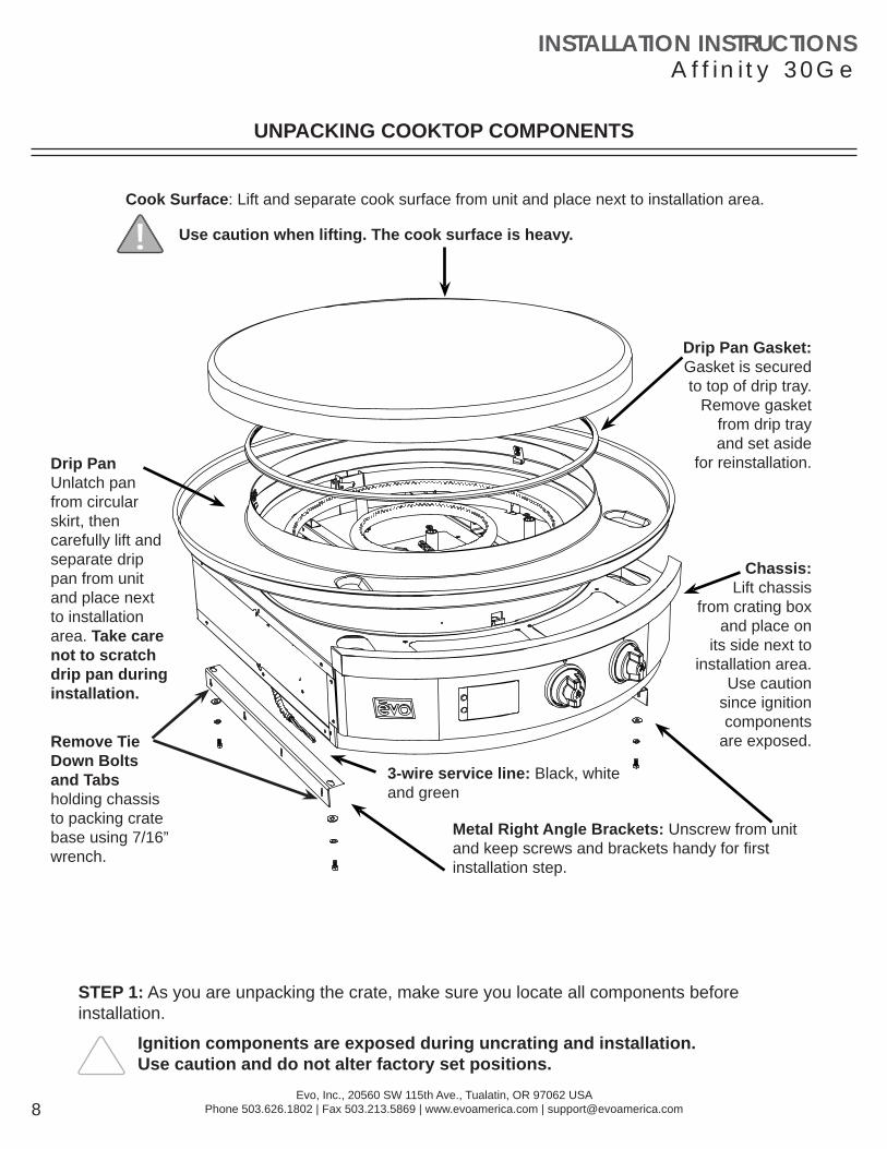
Cook Surface: Lift and separate cook surface from unit and place next to installation area.
Drip Pan Gasket:Gasket is secured to top of drip tray.
Remove gasket from drip tray
and set aside for reinstallation. Drip Pan
Unlatch pan from circular skirt, then carefully lift and separate drip pan from unit and place next to installation area. Take care not to scratch drip pan during installation.
Chassis: Lift chassis
from crating box and place on
its side next to installation area.
Use caution since ignition components
are exposed.
Metal Right Angle Brackets: Unscrew from unit and keep screws and brackets handy for fi rst installation step.
3-wire service line: Black, white and green
UNPACKING COOKTOP COMPONENTS
STEP 1: As you are unpacking the crate, make sure you locate all components before installation.
Ignition components are exposed during uncrating and installation. Use caution and do not alter factory set positions.
Use caution when lifting. The cook surface is heavy.
Remove Tie Down Bolts and Tabs holding chassis to packing crate base using 7/16” wrench.

INSTALLATION INSTRUCTIONSA f f i n i t y 3 0 G e
Evo, Inc., 20560 SW 115th Ave., Tualatin, OR 97062 USAPhone 503.626.1802 | Fax 503.213.5869 | www.evoamerica.com | [email protected] 9
CLEARANCE DIMENSIONS
Read the instructions carefully in this booklet to install the Evo Affi nity 30Ge Cooktop to a metal, stone or wood countertop surface.
Cabinet layout and construction may vary.
Minimum 3” clearance required under unit venting to 22 sq/in of combustible air.
Do not install above any equipment, table or shelving where air temperature is greater than ambient air temperature.
CLEARANCE TO COMBUSTIBLE CONSTRUCTION FROM CHASSISCombustibles Non-combustibles
Back 3/8” 0”Sides 3/8” 0”
Bottom 3” 3”
CLEARANCE TO COMBUSTIBLE CONSTRUCTION FROM COOKING SURFACETop 36”
Sides 12”Back 12”
If installing Evo Affi nity 30Ge next to another 30Ge unit, provide 2” minimum clearance from edge of drip pans.
36” clearance from cooking surface to combustible ceiling materials.
12” clearance from cooking surface to combustible
sidewall materials.
12” clearance from cooking surface to combustible back wall materials.

INSTALLATION INSTRUCTIONSA f f i n i t y 3 0 G e
Evo, Inc., 20560 SW 115th Ave., Tualatin, OR 97062 USAPhone 503.626.1802 | Fax 503.213.5869 | www.evoamerica.com | [email protected]
271932"
701.04mm
2734"
704.85mm
11532"
37.16mm
R1818"
460.38mm
1318"
333.38mm
262332"
678.51mm
131316"
350.52mm
STEP 2: Mark the fi nished position of the Evo Affi nity 30Ge drip pan on the countertop using the dimensions shown. The circular dimension of 18-1/8” is the diameter of the drip pan to the outside fl ange material thickness (located to the inside of the half-rolled bead edge). The drip pan cutout must be made precisely to these dimensions (or at a maximum +1/16”) so that the
half-rolled top bead on the drip pan edge overhangs the cutout dimension by .25”.(See following page for more detail)
Countertop withsubstrate underlayment
OPENING IN COUNTERTOP FRONT
Countertop overhang to cabinet front
Cabinetry Box:minimum 3 cm below countertop surface
TOP VIEW
COUNTERTOP INSTALLATION (1 of 4)
NOTE:If the dimensions for the countertop overhang and countertop depth cutout are not followed, there will be a confl ict with the door swing which allows access to the waste containers.

INSTALLATION INSTRUCTIONSA f f i n i t y 3 0 G e
Evo, Inc., 20560 SW 115th Ave., Tualatin, OR 97062 USAPhone 503.626.1802 | Fax 503.213.5869 | www.evoamerica.com | [email protected] 11
COUNTERTOP INSTALLATION (2 of 4)
CORRECT ALIGNMENT OF DRIP PAN AND CHASSIS TO COUNTERTOP
INCORRECT ALIGNMENT OF DRIP PAN AND CHASSIS TO COUNTERTOP
Possible reasons for incorrect alignment:1. Top of cabinetry box is less than 3 cm
(1.18”) from countertop.2. Chassis mounting brackets are too high.
Black o-ring under drip pan bead
STEP 2 Continued: Make sure cabinetry box is 1-1/2” below countertop surface and mounting brackets are positioned correctly so drip pan and chassis are aligned to countertop. (see diagrams above). A black o-ring is recessed in the top bead and designed to create a seal against the countertop.
Also ensure allowance for the countertop overhang as shown on the SIDE VIEW(see next page).
When you have confi rmed the position is correct, cut the countertop and substrate.

INSTALLATION INSTRUCTIONSA f f i n i t y 3 0 G e
Evo, Inc., 20560 SW 115th Ave., Tualatin, OR 97062 USAPhone 503.626.1802 | Fax 503.213.5869 | www.evoamerica.com | [email protected]
2514"
641.35mm
6916"
166.55mm
3X
7.65in194.36mm
1316"
30mm
22332"
69.21mm
81532"
215.32mm
SIDE VIEW
Example of 3/8” tile with substrate for a minimum 3 cm overall. Make sure you allow for the countertop overhang as shown.
Metal Right Angle Mounting Brackets (supplied)
If desired, shelving or drawers can be installed under the Affi nity 30Ge.
Finished cabinet face set back from fi nished countertop front edge
COUNTERTOP INSTALLATION (3 of 4)

INSTALLATION INSTRUCTIONSA f f i n i t y 3 0 G e
Evo, Inc., 20560 SW 115th Ave., Tualatin, OR 97062 USAPhone 503.626.1802 | Fax 503.213.5869 | www.evoamerica.com | [email protected] 13
1916"
40mm
1316"
30mm
2734"
704.85mm
7.65in194.36mm
Shelving or drawers can be installed under Affi nity 30Ge if desired.
FRONT VIEW
STEP 3: Construct a bay for the Evo unit with your chosen cabinet system. Position and fasten the supplied mounting brackets 7.65” below the fi nished countertop surface.
Metal right angle mounting brackets supplied with unit are each 1/16” thick. Mount angle brackets as shown. Unit slides into framework and rests on top side of brackets. Brackets are slotted for fasteners at each four corners.
Cabinet Framework
Example: Tiled countertop with substrate. Finished countertop thickness should be 3 cm.
COUNTERTOP INSTALLATION (4 of 4)

INSTALLATION INSTRUCTIONSA f f i n i t y 3 0 G e
Evo, Inc., 20560 SW 115th Ave., Tualatin, OR 97062 USAPhone 503.626.1802 | Fax 503.213.5869 | www.evoamerica.com | [email protected]
STEP 4: Slide the Affi nity 30Ge chassis into the countertop so it rests on top of the installed brackets. Bolt unit to angle brackets using supplied 1/4” x 20 fasteners from underside.
3 WIRE SERVICE LINE: Black, White, and Green120V, 1-Phase, 50-60Hz15AMP Circuit
INSERT CHASSIS IN COUNTERTOP
Use supplied 1/4” fasteners to bolt chassis to angle brackets.
Electrical and Gas Installation must be done by a licensed electrician and plumber in accordance with local guidelines once unit has been completely installed. Refer to pages 17-18 and 21 for further instructions.
INSTALLATION INSTRUCTIONSA f f i n i t y 3 0 G e
Evo, Inc., 20560 SW 115th Ave., Tualatin, OR 97062 USAPhone 503.626.1802 | Fax 503.213.5869 | www.evoamerica.com | [email protected] 15
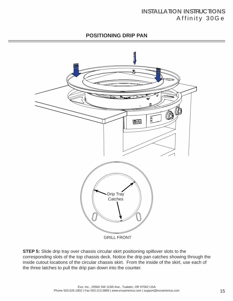
STEP 5: Slide drip tray over chassis circular skirt positioning spillover slots to the corresponding slots of the top chassis deck. Notice the drip pan catches showing through the inside cutout locations of the circular chassis skirt. From the inside of the skirt, use each of the three latches to pull the drip pan down into the counter.
Drip Tray Catches
POSITIONING DRIP PAN
GRILL FRONT

INSTALLATION INSTRUCTIONSA f f i n i t y 3 0 G e
Evo, Inc., 20560 SW 115th Ave., Tualatin, OR 97062 USAPhone 503.626.1802 | Fax 503.213.5869 | www.evoamerica.com | [email protected]
STEP 6: Secure drip pan to chassis using access slot (A). Rewrap drip pan gasket around top of drip tray and secure (B). Ensure seal under drip pan edge is touching countertop(C).
drip pan gasket - seam at rear
(opposite to chef side)
SECURING DRIP PAN AND GASKET
CROSS SECTION OF CHASSIS ACCESS SLOT
Hook drip pan latch under chassis catch and tighten
screw at chassis access slot.
A
Slip gasket ring onto top of drip pan so it creates a seal to
the chassis skirt.
CROSS SECTION OF DRIP PAN TOP
CROSS SECTION OF DRIP PAN EDGE
Ensure the black seal under the drip pan bead edge is touching the countertop.
B C
drip pancountertop
drip panchassis skirt
Use No. 3 Phillips screwdriver to secure drip pan at the
access points.
INSTALLATION INSTRUCTIONSA f f i n i t y 3 0 G e
Evo, Inc., 20560 SW 115th Ave., Tualatin, OR 97062 USAPhone 503.626.1802 | Fax 503.213.5869 | www.evoamerica.com | [email protected]
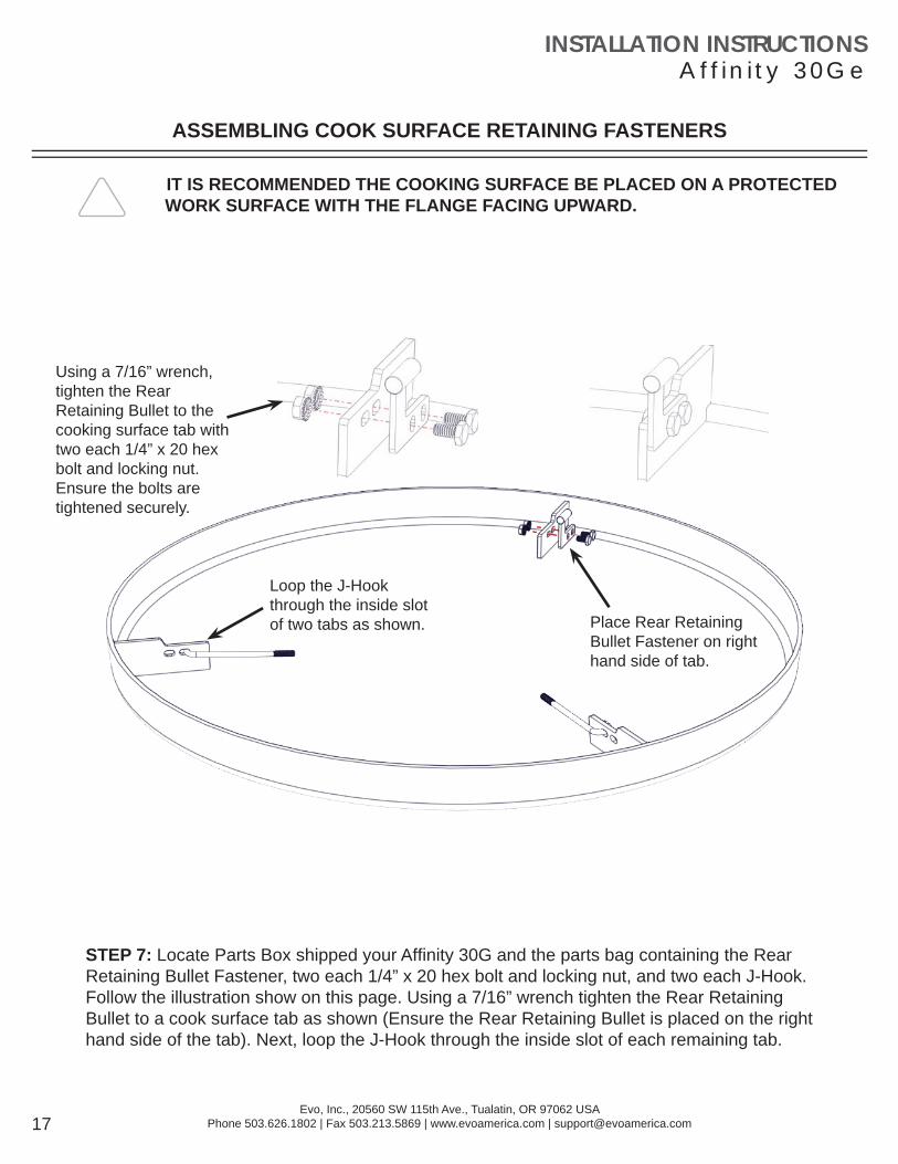
STEP 7: Locate Parts Box shipped your Affi nity 30G and the parts bag containing the Rear Retaining Bullet Fastener, two each 1/4” x 20 hex bolt and locking nut, and two each J-Hook. Follow the illustration show on this page. Using a 7/16” wrench tighten the Rear Retaining Bullet to a cook surface tab as shown (Ensure the Rear Retaining Bullet is placed on the right hand side of the tab). Next, loop the J-Hook through the inside slot of each remaining tab.
ASSEMBLING COOK SURFACE RETAINING FASTENERS
IT IS RECOMMENDED THE COOKING SURFACE BE PLACED ON A PROTECTED WORK SURFACE WITH THE FLANGE FACING UPWARD.
Place Rear Retaining Bullet Fastener on right hand side of tab.
Using a 7/16” wrench, tighten the Rear Retaining Bullet to the cooking surface tab with two each 1/4” x 20 hex bolt and locking nut.Ensure the bolts are tightened securely.
Loop the J-Hook through the inside slot of two tabs as shown.

INSTALLATION INSTRUCTIONSA f f i n i t y 3 0 G e
Evo, Inc., 20560 SW 115th Ave., Tualatin, OR 97062 USAPhone 503.626.1802 | Fax 503.213.5869 | www.evoamerica.com | [email protected]
CONNECTING TEMPERATURE SENSOR WIRE TO COOKING SURFACE
1 Inner Zone
2 Outer Zone
3 Outer Zone4 Outer Zone
1
2
4
3
Place suitable protection on drip pan when tilting cook surface upward.
J-Hook Guide Tube(2 tubes)
J-Hook(2 hooks)
TC Wire(4 wires total)
STEP 8: Place cook surface over circular skirt with the Rear Retaining Bullet facing opposite the front control panel with the bullet resting on the chassis skirt.
STEP 9: Connect TC wires as per diagram and tighten with supplied nuts to each weld-stud location.
POSITION THE COOKING SURFACE ON THE CHASSIS AND ANGLE IT UPWARD TO PROVIDE ACCESS FOR CONNECTING THE TEMPERATURE SENSOR (TC) WIRES.
DO NOT OVER TIGHTEN TC-WIRE HEX NUTS. DOING SO WILL BREAK THREADED WELD STUD ON COOK SURFACE.
WITH THE COOKING SURFACE SUPPORTED IN AN UPRIGHT POSITION, GENTLY PULL EACH TC WIRE UP THROUGH ITS GUIDE TUBE AND ATTACH TO ITS RESPECTIVE THREADED STUD LOCATION ON THE UNDERSIDE OF THE COOKING SURFACE.
TC WireGuide Tube
(4 tubes)
Rear Retaining Bullet Slot
TC Sensor Location

INSTALLATION INSTRUCTIONSA f f i n i t y 3 0 G e
Evo, Inc., 20560 SW 115th Ave., Tualatin, OR 97062 USAPhone 503.626.1802 | Fax 503.213.5869 | www.evoamerica.com | [email protected] 19
POSITIONING TEMPERATURE SENSORS AND LOWERING COOKING SURFACE
TC (Thermal Couple temperature sensor)TC’s are used to electrically monitor the cooking surface temperature at both the inner and outer zones. The Affi nity 30Ge uses K-Value TC’s.
Each TC wire location is illustrated by a number to highlight its corresponding threaded stud location. When the cooking surface is lowered to its fi nal location, the TC wires must be vertically aligned.
The Inner Zone (Inner Burner) has one TC at #1 position. The Outer Zone (Outer Burner) has three TC’s at positions #2, #3, and #4 that are averaged.
Use a wood block (2x4) or similar item to prop surface upward to provide access to TC wires.
STEP 10: Using wood blocks (2x4) or a similar means, lower the cook surface onto the burner chassis with enough space to allow for positioning each TC wire into its respective guide tube. Ensure all excess TC wire is pushed downward through the protective guide tubes and no excess wire is exposed or near a burner tube.
STEP 11: Locate each J-Hook and place through the J-Hook Guide Tube. Continue lowering the cooking surface onto the burner chassis.
Position Rear Retaining Bullet fully to the right side of the retaining slot before lowering cooking surface.
WHEN LOWERING COOK SURFACE ENSURE ALl SLACK TC WIRE IS PUSHED INTO THE PROTECTIVE GUIDE TUBE WITH NO WIRE EXPOSED TO THE BURNERS.

INSTALLATION INSTRUCTIONSA f f i n i t y 3 0 G e
Evo, Inc., 20560 SW 115th Ave., Tualatin, OR 97062 USAPhone 503.626.1802 | Fax 503.213.5869 | www.evoamerica.com | [email protected]
RETAINING COOKING SURFACE
STEP 12: Open both waste doors and at the rear inside corner of the enclosure, tighten nyloc nut on end of J-Hook to retain cooking surface for burner chassis.
Open waste doors to locate end of J-Hook.
Tighten nyloc nut at end of each J-Hook.

INSTALLATION INSTRUCTIONSA f f i n i t y 3 0 G e
Evo, Inc., 20560 SW 115th Ave., Tualatin, OR 97062 USAPhone 503.626.1802 | Fax 503.213.5869 | www.evoamerica.com | [email protected] 21
GAS SUPPLY1/2 PSI Maximum Inlet Gas Pressure1/2” FNPT Pipe Thread
Step 13: Connect Gas using 1/2 psi (max) gas service. All Affi nity gas grills ship pre-confi gured for Natural Gas service unless otherwise indicated on the Safety Label mounted to the right inside spillover drawer. If confi gured for Natural Gas, the internally-regulated pressure is at 4” Water Column (Fixed). If confi gured for LP Propane, the internally-regulated pressure is at 10” Water Column (Fixed). For more information on the gas regular, refer to page 28.
Step 14: Connect Electric 110V 3-Wire Conduit to 110V (AC) grounded electrical service. The external wiring should be mated to conduit of an approved type of fl exible cable suitable for operation at the temperature indicated on the wiring diagram, and of a proper size to carry the load. The supply current should be properly fused and equipped with a means of disconnecting as required by local electrical codes. THE BODY OF THIS COOKTOP MUST BE GROUNDED (DO NOT GROUND TO A GAS SUPPLY LINE). For an electrical schematic, refer to page 27.
HIGHVOLTAGE
DO NOT CONNECT TO AN ELECTRICAL SYSTEM OPERATING AT MORE THAN 120 VOLTS TO GROUND. DO NOT CONNECT TO DIRECT CURRENT (DC). INSTALLATION SHOULD CONFORM TO THE NATIONAL ELECTRIC CODE AND ALL LOCAL ELECTRIC AND GAS RULES AND REGULATIONS.
CONNECTING ELECTRICAL AND GAS
FOR YOUR PROTECTION, A QUALIFIED ELECTRICIAN AND PLUMBER MUST INSTALL THIS COOKTOP. THIS PERSON SHOULD BE FAMILIAR WITH ELECTRICAL AND GAS INSTALLATIONS AND ALL LOCAL CODES. PROPER CONNECTIONS ARE ESSENTIAL FOR SAFE AND EFFICIENT OPERATION.
INLET PRESSURE MUST NOT EXCEED 1/2 PSI!
3 WIRE SERVICE LINE: Black, White, and Green120V, 1-Phase, 50-60Hz15AMP Circuit

OPERATOR INSTRUCTIONSA f f i n i t y 3 0 G e
Evo, Inc., 20560 SW 115th Ave., Tualatin, OR 97062 USAPhone 503.626.1802 | Fax 503.213.5869 | www.evoamerica.com | [email protected]
INNER 000F .Displays temperature for Inner burner (zone) in Fahrenheit degrees whenever Inner control knob is selected. The Dot mark after F is illuminated when burner is ignited. Inner display remains illuminated whenever Inner burner is selected.
OUTER 000F .Displays temperature for Outer burner (zone) in Fahrenheit degrees whenever Outer control knob is selected. The Dot mark after F is illuminated when burner is ignited. Outer display remains illuminated whenever Outer burner is selected.
Depressing the round switch located below the ON/OFF label switches the unit between power On and power Off states. Switching the unit On illuminates a green light above the ON/OFF label indicating the unit is active. Depressing the switch a second time powers down the unit.
ON/OFF
Is illuminated whenever there is a temperature adjustment to the Inner or Outer burner control knobs. SET is the default and remains illuminated until MODE switch is pressed to show ACTUAL temperature.
SET
Is illuminated as a safety feature to indicate cook surface temperature is above 150°F. HOT SURFACEIs illuminated to show actual temperature for both Inner and Outer zones whenever MODE switch is pressed.ACTUAL
Depressing the MODE button momentarily displays the actual temperature at both Inner and Outer zones of the cook surface. When MODE is fi rst pressed, ACTUAL is illuminated to indicate the temperatures displayed are the current temperatures for Inner and Outer zones.
When MODE is held for 4 seconds, the temperature display units change from Fahrenheit (°F) to Celsius (°C).
MODE
DISPLAY PANEL
SET
HO T SUR FA CE
AC TU AL
INNER
OUTER
000F .
000F .
ON/OFF
MODE
OPERATOR INSTRUCTIONSA f f i n i t y 3 0 G e
Evo, Inc., 20560 SW 115th Ave., Tualatin, OR 97062 USAPhone 503.626.1802 | Fax 503.213.5869 | www.evoamerica.com | [email protected]
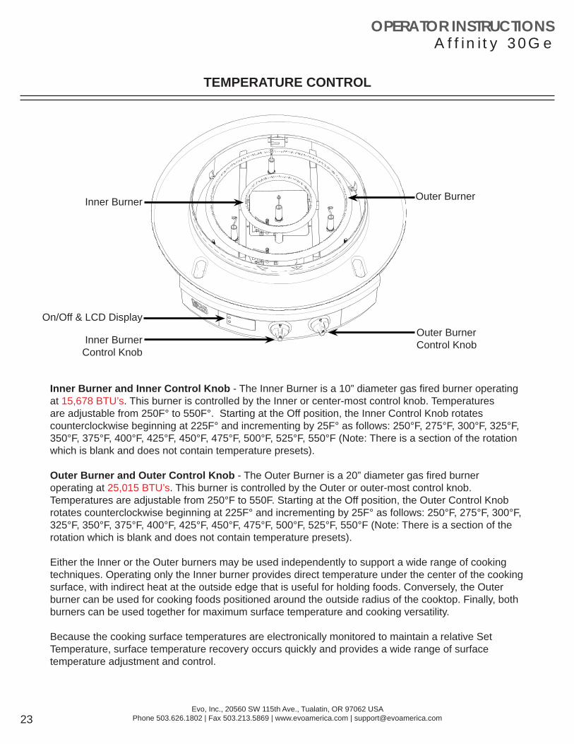
Outer BurnerControl Knob
Inner Burner Outer Burner
On/Off & LCD Display
TEMPERATURE CONTROL
Inner Burner and Inner Control Knob - The Inner Burner is a 10” diameter gas fi red burner operating at 15,678 BTU’s. This burner is controlled by the Inner or center-most control knob. Temperatures are adjustable from 250F° to 550F°. Starting at the Off position, the Inner Control Knob rotates counterclockwise beginning at 225F° and incrementing by 25F° as follows: 250°F, 275°F, 300°F, 325°F, 350°F, 375°F, 400°F, 425°F, 450°F, 475°F, 500°F, 525°F, 550°F (Note: There is a section of the rotation which is blank and does not contain temperature presets).
Outer Burner and Outer Control Knob - The Outer Burner is a 20” diameter gas fi red burner operating at 25,015 BTU’s. This burner is controlled by the Outer or outer-most control knob. Temperatures are adjustable from 250°F to 550F. Starting at the Off position, the Outer Control Knob rotates counterclockwise beginning at 225F° and incrementing by 25F° as follows: 250°F, 275°F, 300°F, 325°F, 350°F, 375°F, 400°F, 425°F, 450°F, 475°F, 500°F, 525°F, 550°F (Note: There is a section of the rotation which is blank and does not contain temperature presets).
Either the Inner or the Outer burners may be used independently to support a wide range of cooking techniques. Operating only the Inner burner provides direct temperature under the center of the cooking surface, with indirect heat at the outside edge that is useful for holding foods. Conversely, the Outer burner can be used for cooking foods positioned around the outside radius of the cooktop. Finally, both burners can be used together for maximum surface temperature and cooking versatility.
Because the cooking surface temperatures are electronically monitored to maintain a relative Set Temperature, surface temperature recovery occurs quickly and provides a wide range of surface temperature adjustment and control.
Inner BurnerControl Knob

OPERATOR INSTRUCTIONSA f f i n i t y 3 0 G e
Evo, Inc., 20560 SW 115th Ave., Tualatin, OR 97062 USAPhone 503.626.1802 | Fax 503.213.5869 | www.evoamerica.com | [email protected] 24
REMOVABLE SPILLOVER TRAYS
The Affi nity grill has removable spillover trays concealed behind doors on the right and left side of the front control panel. It is very important to monitor the level of spillover in the trays, and immediately empty when they are near full
Opening Spillover Tray Doors - To open a door, grasp the door at its bottom and swing outward.
Do not operate cook top or clean drip pan into spillover slots without waste pans installed in spillover doors. Failure to install waste pan will result in cooking grease contamination to the underside of door. This requires immediate cleaning.
RemovableSpillover TraySpillover Tray
Access Door
Spillover Slot
Insert each waste pan all the way to the back of the left and right compartments.
Do not allow spillover liquids or debris down spillover slots when doors are open. Any liquids or debris that may fall into this area when doors are open should be immediately wiped clean.
Do not allow the spillover trays to overfl ow, and do not allow full trays to splash over edge when cleaning. Spillover debris and liquids can be hot and cause burns.
OPERATOR INSTRUCTIONSA f f i n i t y 3 0 G e
Evo, Inc., 20560 SW 115th Ave., Tualatin, OR 97062 USAPhone 503.626.1802 | Fax 503.213.5869 | www.evoamerica.com | [email protected]
Regular cleaning and care for your Evo Affi nity 30Ge cooktop will keep it looking and functioning it’s best.
The cooking surface is designed to hold a fi ne layer of cooking oil creating a ‘seasoning’ on its surface. This seasoning promotes a non-stick cooking surface and is easily maintained.
Caring for Evo’s cooking surface is much like maintaining cast iron cookware. When the surface requires cleaning, there are a few basic cleaning techniques to use. For quick and routine cleaning between preparations, a metal spatula or scraper works for removing the majority of surface debris. For tougher areas or where sugars glaze the cook surface, pour a small amount of warm water on the soiled surface while the grill is warm and scrape the debris away with a spatula. Heat the cook surface to a high temperature and allow the sticky debris to become brittle. Once the debris is brittle, use the spatula or scraper to remove it. Afterwards wipe the cook surface with vegetable oil again before cooking.
To condition the Evo cooking surface you should use the grill cleaning kit supplied with your grill. The grill cleaning kit contains a blue grill pad handle, grill cleaning screen, and grill grey polishing pad. Use the polishing pad after the grill cleaning pads to achieve a smooth cooking surface for the most delicate foods and applications.
To use a grill cleaning screen: With a warm cook surface, place one gray polishing pad between the grill handle base and the grill screen, so the grill screen makes direct contact with the cooking surface. Pour a small amount of vegetable oil on the cook surface and scrub the surface in a circular motion. The gray polishing pad allows excess oil to be absorbed and scours the cooking surface of carbonized debris. When fi nished scrubbing, wipe the surface down with a paper towel or cotton terry cloth.
The drip pan located just below the cook surface is designed to catch food debris and drippings from the cook surface. We recommend cleaning the drip pan after your grill has cooled to prevent the possibility of touching hot adjoining surfaces. The drip pan is easy to wipe out with soap and water using a kitchen sponge. For added convenience, two removable stainless ninth-pans are mounted inside retractable drawers at right and left side of the front control panel for collecting drip pan debris and spill overs. These spillover trays can be easily washed by hand or in a dishwasher. Be sure to empty the spillover trays after every use, and at a minimum, whenever they appear half full.
All the stainless steel components on your grill can be easily polished using a stainless steel cleaner/polish. Stainless steel cleaner can be purchased from the Evo web site along with replacement grill cleaning and polishing pads. The Evo web site address is: www.evoamerica.com.
Cooking Techniques
Stovetop Cooking and Heat ZonesYou can use Evo’s cook surface similar to the burners on your kitchen stove top. Adjust Evo’s heater elements to control the temperatures of the cook surface “heat zones.” Evo’s circular grill top is divided into two distinct zones. The center control panel knob controls the “inner heat zone,” which is also the inner circle of the cook surface at approximately an 11” radius from the center of the cook surface. The outer control panel knob controls the “outer heat zone,” which is the outer circle of the cook surface. Because the cook surface is made of heavy steel, it takes approximately 10 minutes from a cold start to completely heat the surface. With a pre-heated cook surface, if you adjust one of the heater elements, you will have to wait momentarily before the heat zone adjusts to temperature.
Thank You For Cooking With Evo!
COOKING SURFACE MAINTENANCE

APPENDIX - CONTROL COMPONENTSA f f i n i t y 3 0 G e
Evo, Inc., 20560 SW 115th Ave., Tualatin, OR 97062 USAPhone 503.626.1802 | Fax 503.213.5869 | www.evoamerica.com | [email protected] 26
AFFINITY 30GeELECTRICAL SCHEMATICPART #: 10-0050 NG / 10-0050 LP
123456789
Fenw
al 3
5-67
G A S I G N I T I O N
C O N T R O L L E R
12V
L1
120V
L2
TC 1R
1
R2
Out
er
TC 2TC 3
TC 4
DIS
PLA
Y
TEM
P C
ON
TRO
L U
NIT
Rem
ote
Flam
eSe
nse
Hot
Sur
face
Igni
ter
R1
12V
DC
TCU GA
SSO
LEN
OID
VALV
E
123456789
Fenw
al 3
5-67
G A S I G N I T I O N
C O N T R O L L E R
Rem
ote
Flam
eS
ense
Hot
Sur
face
Igni
ter
R2
12V
DC
TCU GA
SS
OLE
NO
IDVA
LVE
Inne
r Bur
ner
Zone
Out
er B
urne
rZo
ne
DO
NO
T C
ON
NE
CT
TO A
N E
LEC
TRIC
AL
SY
STE
M
OP
ER
ATI
NG
AT
MO
RE
TH
EN
120
VO
LTS
TO
GR
OU
ND
.
Evo
, Inc
orpo
rate
d81
40 S
W N
imbu
s A
ve.,
Bldg
5B
eave
rton,
Ore
gon
9700
8 U
SA
THIS
DR
AW
ING
CO
NTA
INS
INFO
RM
ATI
ON
C
ON
FID
EN
TIA
L TO
EV
O, I
NC
. NO
RE
PR
OD
UC
TIO
N
OR
DIS
CLO
SU
RE
OF
ITS
CO
NTE
NTS
IS P
ER
MIT
TED
.
MO
DE
L: A
FFIN
ITY
30G
e E
LEC
TRO
NIC
CO
NTR
OL
GA
S G
RIL
L11
0V /
120V
3-W
IRE
60H
Z
FOR
SU
PP
LY C
ON
NE
CTI
ON
S U
SE
CO
PP
ER
WIR
E O
NLY
S
UIT
AB
LE F
OR
AT
LEA
ST
90°C
(194
°F).
#12
AW
G O
R
LAR
GE
R.

APPENDIX - CONTROL COMPONENTSA f f i n i t y 3 0 G e
Evo, Inc., 20560 SW 115th Ave., Tualatin, OR 97062 USAPhone 503.626.1802 | Fax 503.213.5869 | www.evoamerica.com | [email protected] 27
Pipe Size.......................................................................1/2”
Housing Material................................................Aluminum
Mounting..................................Suitable for multi-positional mounting.
Certifi cations.....................................ANSI Z21.18/CSA 6.3
Gas Types.................Natural or liquefi ed petroleum gases
Maximum Inlet Pressure............................1/2 psi (3.4 kPa)
Emergency Exposure Limits....................2.5 psi (17.2 kPa)
Temperature Ranges................ 32° to 225°F (0° to 107°C)
Pressure Settings Natural Gas - NG ...........4” WC (Fixed)
Pressure Settings Propane Gas - LP..........10” WC (Fixed)
Evo Affi nity 30Ge inlet gas pressure must not exceed 1/2 PSI (maximum) gas service. The Affi nity 30Ge utilizes a factory-set internal gas regulator that accepts 1/2 PSI inlet pressure and outputs 4” W.C. for use by the burner system.
No adjustments to the internal regulator are necessary.
INTERNAL GAS REGULATOR SPECIFICATIONS