Embed Size (px)
Citation preview

Proprietary Information of Marlow Industries, Inc.
OPERATION AND INSTALLATION MANUAL EHPU-X-X-EMR
Cage No.: 55686 Document Number: 103-0029 Revision: 2 Page: 1 of 13
EVERGEN® POWERSTRAP FOR WIRELESS EMERSON ROSEMOUNT SENSORS
Non-invasive thermal energy harvesting power source for Emerson wireless Rosemount sensors
Alternative to replaceable primary cell batteries
Configurable for vertical and horizontal pipes
Designed for pipe diameter ranges from 2”-14”
Operational in most geographic locations
5 minute, non-invasive installation on pipes
Adjustable strap construction with single bolt tightening
Standard 1 year warranty
Class 1 Division 1 Groups A, B, C, & D certified
Patented - US 8,933,317

Proprietary Information of Marlow Industries, Inc.
OPERATION AND INSTALLATION MANUAL EHPU-X-X-EMR
Cage No.: 55686 Document Number: 103-0029 Revision: 2 Page: 2 of 13
1 Contents 2 ENERGY HARVESTING OVERVIEW ......................................................................................................... 3
3 EVERGEN® POWERSTRAP ...................................................................................................................... 3
4 SAFETY GUIDELINES .............................................................................................................................. 4
4.1 EQUIPMENT RATINGS ................................................................................................................... 4
5 COMPONENTS ....................................................................................................................................... 5
6 ORDERING INFORMATION .................................................................................................................... 5
7 SPECIFICATIONS .................................................................................................................................... 6
8 BATTERY LIFE EXTENSION (Years) ......................................................................................................... 7
9 CERTIFICATIONS .................................................................................................................................... 8
9.1 EverGen® PowerStrap Facet .......................................................................................................... 8
9.2 IPM ................................................................................................................................................ 8
10 INSTALLATION ................................................................................................................................... 9
10.1 STRAP MOUNTING ........................................................................................................................ 9
10.2 SENSOR CONNECTION ................................................................................................................ 10
10.3 OPERATIONAL VERIFICATION...................................................................................................... 10
11 TROUBLESHOOTING ........................................................................................................................ 11
12 ENVIRONMENTAL ........................................................................................................................... 11
12.1 DISPOSAL ..................................................................................................................................... 11
12.2 HANDLING CONSIDERATIONS ..................................................................................................... 11
13 DRAWINGS ...................................................................................................................................... 12
14 WARRANTY AND LIABILITY .............................................................................................................. 13
Proprietary Information of Marlow Industries, Inc.
OPERATION AND INSTALLATION MANUAL EHPU-X-X-EMR
Cage No.: 55686 Document Number: 103-0029 Revision: 2 Page: 3 of 13
2 ENERGY HARVESTING OVERVIEW WHAT IS ENERGY HARVESTING? Energy harvesting can be defined as the conversion of various forms of energy from one’s surrounding into useful electrical energy. Wind, thermal, solar radiation, mechanical displacement and vibration are commonly sought after energy sources in energy harvesting applications. WHAT ARE COMMON EXAMPLES OF ENERGY HARVESTING? The most prolific example of energy harvesting is found in solar panels, which convert solar radiation into electrical energy. Piezoelectric transducers are unique materials that covert vibration into electrical energy and are found on industrial equipment (motors, pumps, etc.) to power health monitoring sensors. Thermoelectric modules convert heat from various sources directly into electrical energy. Wind turbines, hydro-power plants and wave generators are also examples of energy harvesters that convert movement in fluid streams (such as air and water) into electrical energy. WHAT IS ENERGY HARVESTING IN REGARDS TO THERMOELECTRICS? Thermoelectric modules consist of solid state semiconductor material that has the unique ability to directly convert thermal (heat) energy into electrical energy. Performance is driven by many variables, but in general, the larger the temperature differential between the source and ambient, the more efficient the performance. A common application for thermoelectric energy harvesting is to power wireless sensors systems where battery replacement and continual servicing is not desired. The ability to operate for decades without the need for regular maintenance is attractive in these applications.
3 EVERGEN® POWERSTRAP WHY IS IT NEEDED? In the industrial world of advanced wireless sensor networks, battery replacement is a high stakes headache played out every day. Not only can battery failures be an inconvenience, but production stops, replacement costs, and lost revenue all eat into business profits. Fortunately, Marlow has developed the EverGen® PowerStrap energy harvester specifically for Emerson’s wireless Rosemount sensors. WHAT DOES IT DO? This product is an easily installed, non-invasive energy harvesting power source that converts heat into electrical energy, perpetually. For those responsible for maintaining communication equipment and sensors (pressure, temperature, flow, etc) on oil pipelines, steam pipelines or other warm process pipes, the Marlow EverGen® PowerStrap makes the job dramatically easier. The EverGen® PowerStrap is designed to provide augmented power to the sensor so that the primary cell battery life can be extended to the shelf life of the battery. In this approach, the battery basically serves as a back-up for the energy harvesting system. HOW DOES IT WORK? The system works by using solid-state (meaning, no moving parts) thermoelectric generators to convert thermal energy from the pipes into useful electricity. This electrical energy is then passed through power conditioning circuitry and stored in super capacitors until your wireless sensor network equipment can utilize it. IS INSTALLATION SIMPLE? Tighten the adjustable strap collar around your process pipe with a single bolt, insert the power module into your wireless sensor, connect wires and start using drawing power from a source that can last for decades.
Proprietary Information of Marlow Industries, Inc.
OPERATION AND INSTALLATION MANUAL EHPU-X-X-EMR
Cage No.: 55686 Document Number: 103-0029 Revision: 2 Page: 4 of 13
4 SAFETY GUIDELINES
4.1 EQUIPMENT RATINGS Pollution Degree: 4 Externally Powered: N/A Altitude: 3000m max Humidity: 10 to 95% Non-Condensing Relative Humidity Ambient Temperature: -40°C to +65°C Maximum Heat Source Surface Temperature: 130°C
Explosions could result in death or serious injury
If the equipment is used in a manner not specified by the manufacturer, the protection provided by the equipment may be impaired
Installation of this product in an explosive environment must be in accordance with the appropriate local, national, and international standards, codes, and practices. Review the Product Certifications section for any restrictions associated with a safe installation.
Before connecting a device in an explosive atmosphere, ensure the instruments are installed in accordance with intrinsically safe or non-incendive field wiring practices.
When installing in a hazardous location, use only appropriately certified plugs, adapters, or glands in cable/conduit entries.
External housing utilizes anodized aluminum, use caution when installing in hazardous locations to prevent sparks.
Electrical shock can result in death or serious injury
Avoid contact with the leads and terminals. High voltage that may be present on leads can cause electrical shock
This product can expose you to a chemical [or chemicals] know to the state of California to cause cancer, birth defects, or other reproductive harm.
The EverGen® PowerStrap is designed for use on warm or hot surfaces and will generate heat itself; a burn hazard could exist. Operators should wear thermal gloves for protection during installation or when handling after installation.
Proprietary Information of Marlow Industries, Inc.
OPERATION AND INSTALLATION MANUAL EHPU-X-X-EMR
Cage No.: 55686 Document Number: 103-0029 Revision: 2 Page: 5 of 13
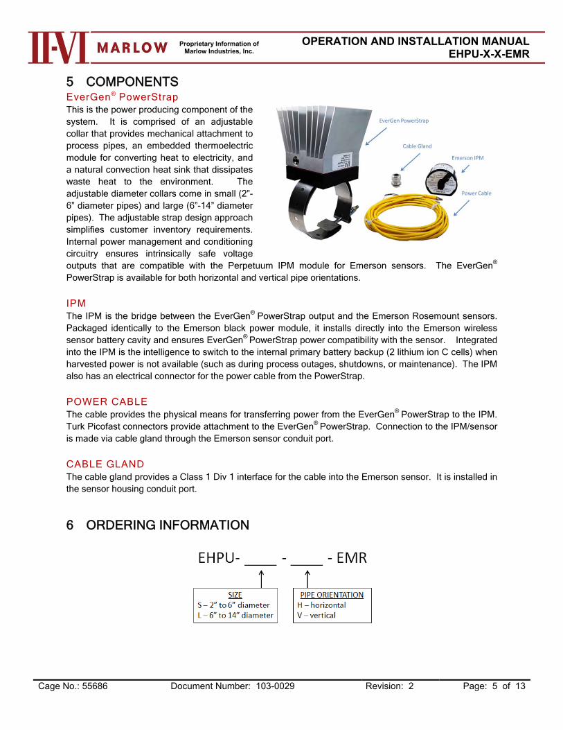
5 COMPONENTS EverGen® PowerStrap This is the power producing component of the system. It is comprised of an adjustable collar that provides mechanical attachment to process pipes, an embedded thermoelectric module for converting heat to electricity, and a natural convection heat sink that dissipates waste heat to the environment. The adjustable diameter collars come in small (2”-6” diameter pipes) and large (6”-14” diameter pipes). The adjustable strap design approach simplifies customer inventory requirements. Internal power management and conditioning circuitry ensures intrinsically safe voltage outputs that are compatible with the Perpetuum IPM module for Emerson sensors. The EverGen® PowerStrap is available for both horizontal and vertical pipe orientations. IPM The IPM is the bridge between the EverGen® PowerStrap output and the Emerson Rosemount sensors. Packaged identically to the Emerson black power module, it installs directly into the Emerson wireless sensor battery cavity and ensures EverGen® PowerStrap power compatibility with the sensor. Integrated into the IPM is the intelligence to switch to the internal primary battery backup (2 lithium ion C cells) when harvested power is not available (such as during process outages, shutdowns, or maintenance). The IPM also has an electrical connector for the power cable from the PowerStrap. POWER CABLE The cable provides the physical means for transferring power from the EverGen® PowerStrap to the IPM. Turk Picofast connectors provide attachment to the EverGen® PowerStrap. Connection to the IPM/sensor is made via cable gland through the Emerson sensor conduit port. CABLE GLAND The cable gland provides a Class 1 Div 1 interface for the cable into the Emerson sensor. It is installed in the sensor housing conduit port.
6 ORDERING INFORMATION

Proprietary Information of Marlow Industries, Inc.
OPERATION AND INSTALLATION MANUAL EHPU-X-X-EMR
Cage No.: 55686 Document Number: 103-0029 Revision: 2 Page: 6 of 13
7 SPECIFICATIONS EverGen® PowerStrap
Life expectancy
Designed for +20 year life Operational parameters
Ambient Operating Temperature Range -40°C < Ta < +65°C
Maximum Hot Surface Temperature 130°C Physical specifications
PowerStrap assembly - 3lbs Electrical connector
Turck MFKS 3F Female Receptacle Conductors: 3 Rated Voltage: 125V Current: 4A Protection Class: NEMA 1, 3, 4,6P and IP67 Electromagnetic compatibility (EMC)
EN55011; 2010, CISPR 11 Ed. 6.0: 2008
Class B Emissions (Radiated) CFR 47, Part 15, Subpart B, Class A, 2011 ICES-003 Issue 4, 2004 CAN/CSA- CISPR
11, Class B EN 61326-1: 2013 EN61000-4-2 Ed. 2.0; 2009: ESD + 8 kV Air,
+ 6 kV Contact EN61000-4-3 Ed. 3.2; 2010: RF Immunity,
3V/m EN61000-4-4 Ed. 3.0; 2012 EFT, 1 kV EN61000-4-8 Ed. 2.0; 2010: Power
Frequency Magnetic Field 3A/m Design Standards
EU RoHS Compliant EU REACH Compliant Enclosure Type 4X, IP66
IPM EC Declaration of Conformity
ATEX Directive (94/9/EC) Certificate Number Baseefa 13ATEX0062X Equipment Group II category 1G Ex ia IIC T4 Ga (-40 °C ≤ Ta ≤ +85 °C)・ ・ Harmonized standards:EN 60079-0:2012
EN 60079-11:2012 ATEX Notified Body for Quality Assurance SIRA Notification number SIRA 07 ATEX M395 Rake Lane Eccleston Chester CH4 9JN Electromagnetic compatibility (EMC)
EMC Directive (2004/108/EC) EN 61326-2-3:2006 (EN 61326-1:2006) & EN 301 489-17 v2.2.1 (EN 301 489-1 v1.9.2)
Proprietary Information of Marlow Industries, Inc.
OPERATION AND INSTALLATION MANUAL EHPU-X-X-EMR
Cage No.: 55686 Document Number: 103-0029 Revision: 2 Page: 7 of 13
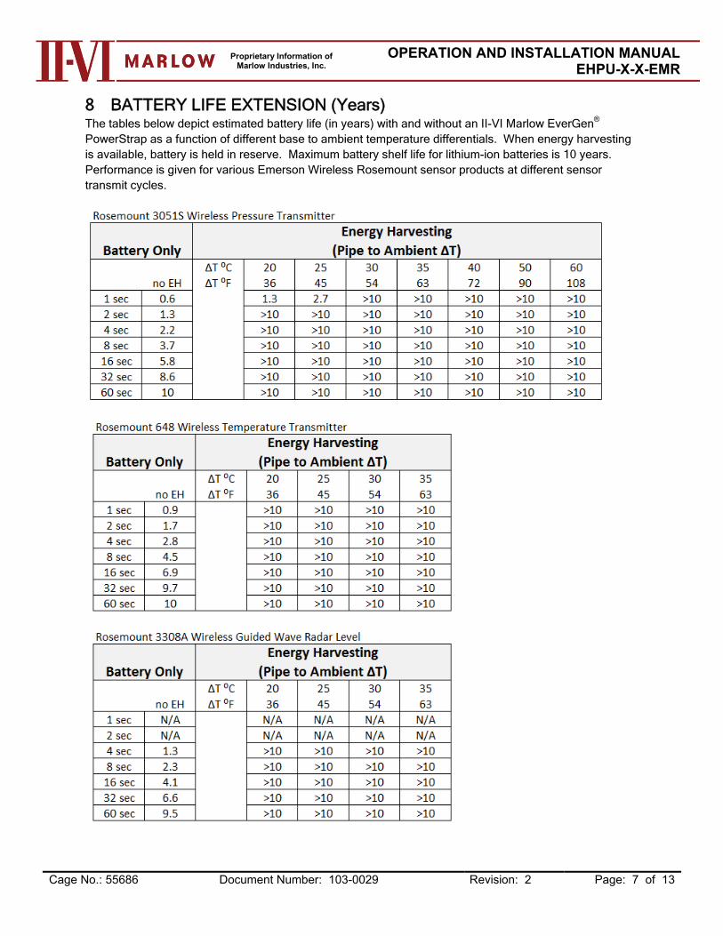
8 BATTERY LIFE EXTENSION (Years) The tables below depict estimated battery life (in years) with and without an II-VI Marlow EverGen®
PowerStrap as a function of different base to ambient temperature differentials. When energy harvesting is available, battery is held in reserve. Maximum battery shelf life for lithium-ion batteries is 10 years. Performance is given for various Emerson Wireless Rosemount sensor products at different sensor transmit cycles.
Proprietary Information of Marlow Industries, Inc.
OPERATION AND INSTALLATION MANUAL EHPU-X-X-EMR
Cage No.: 55686 Document Number: 103-0029 Revision: 2 Page: 8 of 13
9 CERTIFICATIONS
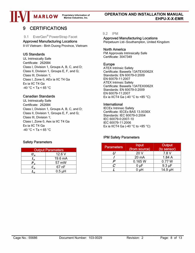
9.1 EverGen® PowerStrap Facet Approved Manufacturing Locations II-VI Vietnam – Binh Duong Province, Vietnam US Standards UL Intrinsically Safe Certificate: 262684 Class I, Division 1, Groups A, B, C, and D; Class II, Division 1, Groups E, F, and G; Class III, Division 1; Class I, Zone 0, AEx ia IIC T4 Ga Ex ia IIC T4 Ga -40 °C < Ta < 65 °C Canadian Standards UL Intrinsically Safe Certificate: 262684 Class I, Division 1, Groups A, B, C, and D; Class II, Division 1, Groups E, F, and G; Class III, Division 1; Class I, Zone 0, Aex ia IIC T4 Ga Ex ia IIC T4 Ga -40 °C < Ta < 65 °C Safety Parameters
Output Parameters 12.6 V 19.6 mA 57 mW 67 nF 0.5 µH
9.2 IPM Approved Manufacturing Locations Perpetuum Ltd—Southampton, United Kingdom North America FM Approvals Intrinsically Safe Certificate: 3047349 Europe ATEX Intrinsic Safety Certificate: Baseefa 13ATEX0062X Standards: EN 60079-0:2009 EN 60079-11:2007 ATEX Intrinsic Safety Certificate: Baseefa 13ATEX0062X Standards: EN 60079-0:2009 EN 60079-11:2007 Ex ia IICT4 Ga (-40 °C to +85 °C) International IECEx Intrinsic Safety Certificate: IECEx BAS 13.0036X Standards: IEC 60079-0:2004 IEC 60079-0:2007-10 IEC 60079-11:2006 Ex ia IICT4 Ga (-40 °C to +85 °C) IPM Safety Parameters
Parameters Input
(from source) Output
(to sensor) U 20 V 7.8 V I 20 mA 1.84 A P 0.165 W 0.77 W C 0 µF 9.3 µF L 0 µH 14.9 µH

Proprietary Information of Marlow Industries, Inc.
OPERATION AND INSTALLATION MANUAL EHPU-X-X-EMR
Cage No.: 55686 Document Number: 103-0029 Revision: 2 Page: 9 of 13
10 INSTALLATION
10.1 STRAP MOUNTING Ensure the heat source is turned off/removed and the pipe is at ambient temperature. Choose a pipe installation location that does not exceed a maximum temperature of 130C and allows
the PowerStrap to be installed with ample clearance to allow air flow through the heatsinks. Do not cover the heatsinks.
Clean pipe surface of any excess dirt or debris that could inhibit heat transfer from the pipe to the PowerStrap.
Orientation of the PowerStrap can affect the overall performance of the system. Units must be purchased preconfigured with either the vertical or horizontal configuration. The unit must be mounted with the heatsink fins aligned perpendicular to the ground to enhance natural convection air flow. The external connector should be positioned down to prevent the external cable from interfering with the heatsink.
The PowerStrap has an adjustable strap band that allows for custom fitting to a range of pipe sizes. The following templates indicate the strap hole locations that correspond to the given NPS pipe size.

Proprietary Information of Marlow Industries, Inc.
OPERATION AND INSTALLATION MANUAL EHPU-X-X-EMR
Cage No.: 55686 Document Number: 103-0029 Revision: 2 Page: 10 of 13
Insert the T-bolt into the appropriate hole and follow the procedure below for setting the strap to the
appropriate diameter.
Connect the accompanying cable to the external connector of the PowerStrap. Check to make sure
pins are aligned, and then thread the cable connector until secure.
10.2 SENSOR CONNECTION Follow all local codes and regulations for sensor connection. Insert the provided cable gland into the ½” threaded conduit port on the Emerson sensor. Use Teflon
tape and tighten to manufacturers recommended torque. Trim about ¼ inch of insulation from the positive and negative leads of the cable from the PowerStrap. Remove the sensor housing battery cover and insert the cable from the PowerStrap through the cable
gland and connect to the IPM module provided. Connections are made as described in the table. Not all wires are used.
Brown Wire Blue Wire Black Wire
Positive Not used Negative
Insert IPM into battery cavity and connect to sensor. Replace the sensor battery cover. Sensor will power up from the internal primary cell battery in the
IPM. Tighten cable glands to prevent water ingress. Activate the heat source. The PowerStrap will begin to power the sensor once the pipe to ambient
temperature differential reaches 20C. See battery life extension tables for expected performance.
10.3 OPERATIONAL VERIFICATION After installation, it is recommended to verify the EverGen® PowerStrap is operating properly in the field. Always follow local site installation procedures.
Proprietary Information of Marlow Industries, Inc.
OPERATION AND INSTALLATION MANUAL EHPU-X-X-EMR
Cage No.: 55686 Document Number: 103-0029 Revision: 2 Page: 11 of 13
To verify the strap operation, allow the heat source to reach operating temperature. Allow the strap to absorb heat from the heated pipe for 5-10 minutes. Using a multi-meter set to read DC voltage, read the output voltage of the PowerStrap cable positive and negative leads. Expected output range for the PowerStrap is 10-12 VDC.
11 TROUBLESHOOTING Upon completion of the operational verification, if the supply output is less than expected then the PowerStrap may not be operating properly. If necessary, follow these steps;
Use temperature measuring device to register the baseplate temperature of the PowerStrap. Ensure that a minimum ambient-to-source temperature differential of 20C is present. This temperature differential is necessary to ensure that the internal power management circuitry is receiving adequate input from the PowerStrap to power the sensor.
Check connection between cable and the external connector and verify it is secure and properly connected.
Check the torque on the mounting screws to verify the PowerStrap is mounted securely to the hot source.
If product is still not operating correctly, contact our technical support team to resolve the issue. Do not attempt to disassemble or repair product. Doing so could result in permanent damage to the thermoelectric or other system components.
By Telephone: 1-877-627-5691
On the Web: www.marlow.com
12 ENVIRONMENTAL
12.1 DISPOSAL Dispose of in accordance with applicable laws and regulations in your country and state. Disposal should only be performed by authorized professionals in accordance with applicable
requirements.
12.2 HANDLING CONSIDERATIONS Use caution when installing in hazardous locations, the external housing utilizes anodized aluminum
which can generate sparks. Fins can be damaged if dropped onto hard surfaces. This can reduce performance output of the
product.

Proprietary Information of Marlow Industries, Inc.
OPERATION AND INSTALLATION MANUAL EHPU-X-X-EMR
Cage No.: 55686 Document Number: 103-0029 Revision: 2 Page: 12 of 13
13 DRAWINGS
Small PowerStrap

Proprietary Information of Marlow Industries, Inc.
OPERATION AND INSTALLATION MANUAL EHPU-X-X-EMR
Cage No.: 55686 Document Number: 103-0029 Revision: 2 Page: 13 of 13
14 LIMITED WARRANTY AND LIABILITY
WE WARRANT THAT DURING THE WARRANTY PERIOD, THE PRODUCT WILL BE FREE
FROM DEFECTS IN MATERIALS AND WORKMANSHIP AND THE PRODCT WILL CONFORM TO OUR WORKMANSHIP STANDARDS AS SPECIFIED IN OUR QUALITY CONTROL MANUAL. WE ADDITIONALLY WARRANT THAT AT THE TIME OF DELIVERY WE HAVE TITLE TO THE PRODUCT FREE AND CLEAR OF ANY AND ALL LIENS AND ENCUMBRANCES UNLESS OTHERWISE PROVIDED IN OUR CONTRACT WITH THE PURCHASER.
EXCEPT FOR THE EXPRESS LIMITED WARRANTY SET FORTH HEREIN, WE EXPRESSLY DISCLAIM ALL OTHER WARRANTIES (EXPRESS OR IMPLIED) WITH RESPECT TO THE PRODUCT, INCLUDING, WITHOUT LIMITATION, ANY IMPLIED WARRANTIES OF MERCHANTABILITY OR OF FITNESS OF USE FOR A PARTICULAR PURPOSE, IMPLIED WARRANTY AGAINST INTERFERENCE, IMPLIED WARRANTY AGAINST INFRINGEMENT, AND ANY OTHER IMPLIED WARRANTIES TO THE FULLEST EXTENT PERMITTED BY STATE OR FEDERAL LAW, WHETHER ARISING BY LAW, COURSE OF DEALING, COURSE OF PERFORMANCE, USAGE OF TRADE OR OTHERWISE.
EXCEPT AS EXPRESSLY SET FORTH HEREIN, MARLOW’S SOLE OBLIGATION IN THE EVENT OF ANY EXPRESS OR IMPLIED WARRANTY SHALL BE TO REPAIR OR REPLACE SUCH PRODUCT.
Marlow Industries, Inc., located at 10451 Vista Park Road, Dallas, Texas 75238 ("we") extend this limited warranty only to the original purchaser of this product ("you"). It does not extend to any subsequent owner or other transferee of the product.
This limited warranty does not cover any damage due to: (1) transportation; (2) storage; (3) improper use; (4) failure to follow the product instructions or to perform any preventive maintenance; (5) modifications; (6) unauthorized repair; (7) normal wear and tear; or (8) external causes such as accidents, abuse, or other actions or events beyond our reasonable control.
This limited warranty starts on the date of delivery of the product to the purchaser and extends for a period of one year thereafter ("Warranty Period"). The Warranty Period is not extended if we repair or replace the product.
With respect to any defective product during the Warranty Period, we will, in our sole discretion repair or replace such product (or the defective part) free of charge. We will also pay for shipping and handling fees to return the repaired or replacement product to you.
LIMITATION OF LIABILITY
THE REMEDIES DESCRIBED ABOVE ARE YOUR SOLE AND EXCLUSIVE REMEDIES AND OUR ENTIRE LIABILITY FOR ANY BREACH OF THIS LIMITED WARRANTY. OUR LIABILITY SHALL UNDER NO CIRCUMSTANCES EXCEED THE ACTUAL AMOUNT PAID BY YOU FOR THE DEFECTIVE PRODUCT, NOR SHALL WE UNDER ANY CIRCUMSTANCES BE LIABLE