Embed Size (px)
Citation preview

chr
Towbarless Towing Vehicle Operations—Evaluation of Braking Action and Vehicle Conspicuity Gordon F. Hayhoe and James Patterson, Jr. August 2009 DOT/FAA/AR-TN09/44 This document is available to the U.S. public through the National Technical Information Service (NTIS), Springfield, Virginia 22161
U.S. Department of Transportation Federal Aviation Administration
ote
tech
nica
l not
e te
chni
ca
NOTICE
This document is disseminated under the sponsorship of the U.S. Department of Transportation in the interest of information exchange. The United States Government assumes no liability for the contents or use thereof. The United States Government does not endorse products or manufacturers. Trade or manufacturer's names appear herein solely because they are considered essential to the objective of this report. This document does not constitute FAA certification policy. Consult your local FAA airport certification office as to its use.
This report is available at the Federal Aviation Administration William J. Hughes Technical Center’s Full-Text Technical Reports page: actlibrary.act.faa.gov in Adobe Acrobat portable document format (PDF).

Technical Report Documentation Page
1. Report No. DOT/FAA/AR-TN09/44
2. Government Accession No. 3. Recipient's Catalog No.
4. Title and Subtitle TOWBARLESS TOWING VEHICLE OPERATIONS—EVALUATION OF BRAKING ACTION AND VEHICLE CONSPICUITY
5. Report Date August 2009
6. Performing Organization Code
7. Author(s) Gordon F. Hayhoe and James Patterson, Jr.
8. Performing Organization Report No.
9. Performing Organization Name and Address Federal Aviation Administration William J. Hughes Technical Center Airport and Aircraft Safety Group Airport Technology Research and Development Team Atlantic City International Airport, NJ 08405
10. Work Unit No. (TRAIS)
11. Contract or Grant No.
12. Sponsoring Agency Name and Address U.S. Department of Transportation Federal Aviation Administration Office of Airport Safety & Standards (Air Traffic Organization Operations Planning) Washington, DC 20591
13. Type of Report and Period Covered Technical Note
14. Sponsoring Agency Code AAS-100
15. Supplementary Notes The Federal Aviation Administration Airport and Aircraft Safety Group Technical Officer was Dr. S. K. Agrawal. 16. Abstract General guidance on the operation of towbarless towing vehicles (TLTV) on airport operation areas is discussed with respect to braking during towing emergencies, painting, and lighting the TLTV and the aircraft being towed. Evaluations and recommendations are also given with regard to the topics discussed in the report. The braking evaluation was prompted by a runway incursion involving a Goldhofer AST-2 tractor and a Boeing 777 aircraft in which the 777 had none of its systems operational and no personnel present in the cockpit. A simulation analysis, conducted as part of the evaluation, indicates that a person in the cockpit qualified to apply the aircraft brakes probably could have stopped the TLTV/aircraft combination before the hold line and excessive damage would not have been caused to the nose gear of the aircraft during the aircraft braking action. This finding cannot be applied to other TLTV/aircraft combinations without analysis specific to that combination. The evaluation of painting and lighting (conspicuity) concerns was prompted by a number of airports reporting difficulty in seeing aircraft when being towed at night, particularly when the aircraft systems are not operational. The evaluation determined that TLTV/aircraft conspicuity may be increased by using brighter paint colors, reflective tape along the lower body panels of the TLTV, and additional warning lights on the body of the TLTV. 17. Key Words Towbarless towing vehicle, TLTV, Conspicuity, Vehicle marking, Vehicle lighting, TLTV braking, Super tug
18. Distribution Statement This document is available to the U.S. public through the National Technical Information Service (NTIS), Springfield, Virginia 22161.
19. Security Classif. (of this report) Unclassified
20. Security Classif. (of this page) Unclassified
21. No. of Pages 34
22. Price
Form DOT F 1700.7 (8-72) Reproduction of completed page authorized

TABLE OF CONTENTS Page EXECUTIVE SUMMARY ix INTRODUCTION 1
Background 1 Purpose 1 Scope 1 Objectives 2
AIRCRAFT BRAKING DURING TLTV MAINTENANCE TOWING 2 Introduction 2 Discussion of Aircraft Braking During Maintenance Towing 2 Analysis of Horizontal Nose Gear Forces Resulting From Tractor and Aircraft Braking 4 Conclusions of Aircraft Braking 14
CONSPICUITY OF TLTV AND AIRCRAFT 15
Introduction 15 Discussion 16
TLTV Paint Color 16 TLTV Marking 17 TLTV Lighting 18 Aircraft Lighting 19
Conclusions of TLTV and Aircraft Conspicuity 21
REFERENCES 22 APPENDICES
A—Excerpts From Boeing Document D6-56872 B—AST-2 Tractor Specifications
iii

LIST OF FIGURES Figure Page 1 Velocities of Aircraft, Tractor, and Tractor Relative to Aircraft for a Step Input
of Tractor Braking at an Initial Speed of 20 mph, Aircraft Weight = 410,000 lb, and Stopping Distance = 212.5 ft 5
2 Horizontal Nose Gear Tow Load Force for a Step Input of Tractor Braking at
an Initial Speed of 20 mph, Aircraft Weight = 410,000 lb, and Maximum Tow Load = 46,500 lb 5
3 Time History From Goldhofer Report 7 4 Velocities of Aircraft, Tractor, and Tractor Relative to Aircraft for a 1-Second Ramp
Input of Tractor Braking at an Initial Speed of 20 mph, Aircraft Weight = 410,000 lb, and Stopping Distance = 226.1 ft 7
5 Horizontal Nose Gear Tow Load Force for a 1-Second Ramp Input of Tractor
Braking at an Initial Speed of 20 mph, Aircraft Weight = 410,000 lb, and Maximum Tow Load = 24,660 lb 8
6 Velocities of Aircraft, Tractor, and Tractor Relative to Aircraft for a 1-Second Ramp
Input of Aircraft Braking at an Initial Speed of 20 mph, Aircraft Weight = 410,000 lb, and Stopping Distance = 40.9 ft 9
7 Horizontal Nose Gear Tow Load Force for a 1-Second Ramp Input of Aircraft
Braking at an Initial Speed of 20 mph, Aircraft Weight = 410,000 lb, and Maximum Tow Load = 18,360 lb 9
8 Horizontal Nose Gear Tow Load Force for a Step Input of Aircraft Braking at
an Initial Speed of 20 mph, Aircraft Weight = 410,000 lb, Maximum Tow Load = 34,940 lb, and Stopping Distance = 26.9 ft 10
9 Velocities of Aircraft, Tractor, and Tractor Relative to Aircraft for a 1-Second Ramp
Input of Aircraft Braking at an Initial Speed of 20 mph, Aircraft Weight = 130,000 lb, and Stopping Distance = 45.7 ft 10
10 Horizontal Nose Gear Tow Load Force for a 1-Second Ramp Input of Aircraft
Braking at an Initial Speed of 20 mph, Aircraft Weight = 130,000 lb, Maximum Tow Load = 16,600 lb, and Stopping Distance = 45.7 ft 11
11 Horizontal Nose Gear Tow Load Force for a Step Input of Aircraft Braking at an
Initial Speed of 20 mph, Aircraft Weight = 130,000 lb, Maximum Tow Load = 29,790 lb, and Stopping Distance = 31.6 ft 11
iv
v
12 Predicted Nose Gear Force due to Aircraft Braking Compared With the Tow Load Limits Specified in Boeing Document D6-56872 for the Range of Aircraft Rated for use With the AST-2 Tractor 14
13 A Goldhofer AST-2 TLTV Towing a 777 15 14 A Goldhofer AST-2 Painted Red 17 15 The TLTV Warning Light Locations 18 16 Engine Nacelle Blocking the Warning Lights 19 17 A TLTV Towing a 777 at Night 20 18 Aircraft With Taxi Lights On 21

LIST OF TABLES Table Page 1 Summary of the Simulation Results for Tractor Braking Only and Aircraft
Braking Only 12
vi

LIST OF ACRONYMS AC Advisory Circular ATC Air traffic control DFW Dallas Fort Worth International Airport FAA Federal Aviation Administration GVW Gross vehicle weight ORD Chicago O’Hare International Airport TLTV Towbarless Towing Vehicle
vii/viii

EXECUTIVE SUMMARY Several aircraft towing tractor manufacturers have constructed new, large tractors that are capable of towing large airplanes without the use of a traditional tow bar. These vehicles, often called super tugs or towbarless towing vehicles (TLTV) capture and pick up the nose gear of the aircraft, which allows the TLTV to travel at higher speeds than typically permitted when using a tow bar. Airlines are purchasing these new TLTVs because they offer a rapid, low-cost method of transporting aircraft in maintenance tows as well as pushbacks. Significant amounts of fuel can be saved because the aircraft engines do not have to be used to propel the aircraft. At the present time, airlines are using TLTVs for maintenance operations that are frequently conducted at night, when the aircraft is being repositioned between a gate and a maintenance facility. In April 2008, maintenance personnel from American Airlines were conducting a typical maintenance towing operation with a Goldhofer AST-2 TLTV towing a Boeing 777. None of the aircraft systems were operational and no personnel were in the cockpit of the aircraft. On being asked to hold short before crossing an active runway, the TLTV operator applied the service brakes and then experienced a bucking motion. The TLTV and the aircraft subsequently crossed the hold line. The braking efficiency of TLTV/aircraft combinations under these circumstances needed to be evaluated. A simulation analysis was conducted of the braking motion of an AST-2/777 combination with tractor braking only and aircraft braking only. The results of the simulation analysis indicated that having a qualified person in the cockpit to apply the aircraft brakes probably would have allowed the TLTV/aircraft combination to be stopped before crossing the hold line and would not have caused excessive damage to the nose gear of the aircraft during the aircraft braking action. This finding cannot be applied to other TLTV/aircraft combinations without analysis specific to that combination. Using TLTVs on an airport surface at night has raised a concern regarding their conspicuity when towing an unpowered aircraft. One of the primary advantages of TLTVs is that they quickly move an aircraft at speeds of 15 mph or more without the aid of the aircraft’s auxiliary power unit, hydraulic systems, or engines. As a result, some airlines have elected not to turn on the aircraft’s external and internal lighting during nighttime towing. Several airports that have TLTV operations have reported problems with TLTV conspicuity when they are towing aircraft on a runway or taxiway at night, due to the lack of sufficient lighting or markings. An evaluation of the conspicuity issues determined that TLTV conspicuity may be increased by using brighter paint colors, reflective tape along the lower body panels of the TLTV, and additional warning lights on the body of the TLTV.
ix/x

INTRODUCTION BACKGROUND. Several aircraft towing tractor manufacturers have constructed new, large tractors that are capable of towing large airplanes without using a traditional tow bar. These vehicles, often called super tugs or towbarless towing vehicles (TLTV) capture and pick up the nose gear of the aircraft, which allows the TLTV to travel at higher speeds than typically permitted when using a tow bar. Airlines are purchasing these new TLTVs because they offer a rapid, low-cost method of transporting aircraft in maintenance tows as well as pushbacks. Significant amounts of fuel can be saved because the aircraft engines are not needed to propel the aircraft. At the present time, airlines are using TLTVs for maintenance operations that are frequently conducted at night, when the aircraft is being repositioned between a gate and a maintenance facility. In April 2008, maintenance personnel from American Airlines were conducting a typical maintenance towing operation at Dallas/Fort Worth International Airport (DFW) with a Goldhofer AST-2 TLTV towing a Boeing 777. None of the aircraft systems were operational and no personnel were in the cockpit of the aircraft. On being asked to hold short before crossing an active runway, the TLTV operator applied the service brakes and then experienced a bucking motion. The TLTV and the aircraft subsequently crossed the hold line. Therefore, the braking efficiency of TLTV/aircraft combinations under these circumstances needed to be evaluated. Using TLTVs on an airport surface at night has raised a concern regarding their conspicuity when towing an unpowered aircraft. One of the primary advantages of TLTVs is that they quickly move an aircraft at speeds up to 15 mph without the aid of the aircraft’s auxiliary power unit, hydraulic systems, or engines. As a result, some airlines have elected not to turn on the aircraft’s external and internal lighting during nighttime towing. Several airports that have TLTV operations have reported problems with TLTV conspicuity when they are towing aircraft on a runway or taxiway at night, possibly due to insufficient lighting or markings on the TLTV. PURPOSE. This report describes work conducted by the Federal Aviation Administration (FAA) Airport Technology Research and Development Team to investigate potential braking issues with TLTVs that are towing Boeing 777 aircraft, and potential issues with TLTV conspicuity during tow operations on the airport operations area. The work was conducted at the request of the FAA Office of Airport Safety and Standards, Airport Engineering Division. SCOPE. This research effort focused on TLTV operations throughout the nation, including all air carriers, manufacturers, and airports known to be operating TLTVs. Special attention was paid to the event at DFW, as it is the only officially documented case where TLTV braking is in question. Furthermore, the conspicuity issue focused on reports received from Chicago O’Hare
1

International Airport (ORD) and DFW, as they are the only airports that have reported issues with conspicuity. OBJECTIVES. There were two main objectives to this research effort. They were to: • investigate concerns regarding the braking behavior of TLTV/aircraft combinations
during maintenance towing operations. • investigate concerns regarding the optimal method for lighting and marking a TLTV and
the aircraft that it is towing during both day- and nighttime conditions within the airport operation area.
AIRCRAFT BRAKING DURING TLTV MAINTENANCE TOWING
INTRODUCTION. On April 6, 2008, a Goldhofer AST-2F-400 Towbarless Towing Vehicle (TLTV) failed to stop in time to avoid a runway incursion while maintenance towing an American Airlines Boeing 777 toward an active runway. The failure to stop was reported as being due to a “bucking” instability of the TLTV relative to the airplane, which developed after applying the tractor’s service brake. During the tow, no personnel were onboard the aircraft and none of the aircraft systems were operational. Control of the aircraft’s motion was provided solely by the TLTV and its driver. In view of the reported instability, and consequently, the TLTV driver’s reduced ability to operate the controls, it is probable that braking action by a qualified person in the cockpit could have brought the TLTV aircraft combination to a stop without crossing the hold line and triggering an incursion incident. However, The Boeing Company recommends that aircraft braking not be used during TLTV towing operations because it runs the risk of damaging the aircraft’s nose gear. A comparative analysis is given of the expected longitudinal forces experienced by the nose gear of an aircraft being towed by an AST-2F-400 during tractor and aircraft braking. Tractor braking only is considered first, followed by aircraft braking only. For the full range of Boeing aircraft specified by Goldhofer for maintenance towing with the AST-2F-400 (see appendix B), the estimated maximum nose gear forces with aircraft braking only are compared with the maximum allowable nose gear forces specified by Boeing. In this report, AST-2 refers to the AST-2F-400 model only. The statements and conclusions should not be considered to be applicable to any other TLTV model without further analysis. DISCUSSION OF AIRCRAFT BRAKING DURING MAINTENANCE TOWING. Boeing Service Letter ATA: 0910-00 [1], provides guidance on the use of TLTVs with regard to the service life of aircraft components, particularly the nose gear structure, during maintenance towing operations. Boeing document D6-56872 [2], provides requirements for testing and
2

evaluating the loads exerted on the nose gear of an aircraft being towed by a TLTV and is attached to the service letter. Quoting from the service letter:
“At the request of airlines, Boeing released the attached Document D6-56872; ‘Towbarless Towing Vehicle Assessment Criteria’ which is applicable for TLTVs that attach to the nose gear and which have hydrostatic or hydrodynamic drive systems. Boeing used previously gathered data to develop the criteria in the specification and to date only these TLTVs with hydrostatic and hydrodynamic drives have been tested by Boeing. The purpose of this specification is to give operators and TLTV manufacturers the requirements needed to self-test and self-evaluate the effects of TLTVs on Boeing referenced airplanes without a Boeing contract or participation. These evaluations should enable vehicle manufactures and operators to determine if the loads induced by the TLTV will exceed the design loads of the nose gear, or induce instability during pushback and/or maintenance towing operations.”
The service letter also states:
“The FAA currently has no restrictions on towbarless towing for either new model or in-service airplanes. However, for all models, Boeing recommends that a qualified individual be present on the flight deck during all towing operations, including towing using Towbarless tow vehicles. Our reasons are based on avoiding personnel injury and airplane damage.”
Followed by:
“Boeing has determined that the application of airplane brakes during towbarless towing may result in airplane and tow vehicle damage for certain vehicle/airplane combinations. Flagnote [1] on the attached matrix (Table 1) identifies these critical combinations. TLTVs tested to date by Boeing have no structural fuse to limit the loads during airplane braking. The loads experienced during airplane braking could result in gear damage or gear collapse, with consequential tow vehicle and airplane damage and injury to personnel. For this and other reasons, Boeing does not recommend the application of airplane brakes during towing.”
Section 8.2 of Boeing document D6-56872 expressly recommends that sudden aircraft braking not be applied at any time during a TLTV towing operation:
“The airplane brakes should not be used while being towed by a TLTV. Airplane braking while an airplane is under tow may result in loads exceeding the airplane design loads and may result in structural damage and/or nose gear collapse. For these, and other reasons, Boeing recommends that airlines take appropriate steps to prevent airplane braking during Towbarless towing. Boeing recommends TLTV’s incorporate a structural fuse or an automatic decoupling device to reduce the potential risks associated with airplane braking.”
3

Despite these warnings against aircraft braking, allowing an operator in the cockpit of a 777 being towed by an AST-2 to apply the aircraft brakes would greatly reduce the severity of the consequences of incidents similar to the DFW incident, provided the nose gear is not severely damaged as a result. Boeing’s service letter identifies the critical airplane and TLTV combinations that may be susceptible to nose gear damage during aircraft braking. However, the AST-2/777 combination is not yet listed in the service letter, and the criteria for identifying such combinations are not given. A simulation analysis was therefore performed to estimate the magnitude of nose gear loads caused by aircraft braking. Test data is not available for nose gear loads measured during aircraft braking only, so an analysis of the nose gear loads during tractor braking only was done first to compare with the measurements made by Goldhofer when running the Boeing D6-56872 tests for an AST-2/767 combination. ANALYSIS OF HORIZONTAL NOSE GEAR FORCES RESULTING FROM TRACTOR AND AIRCRAFT BRAKING. The simulation model has two degrees of freedom: longitudinal motion of the aircraft and longitudinal motion of the tractor. The two bodies are connected by a linear spring representing the nose gear. The maximum braking effort from the AST-2 brakes was set at 26,240 lb (11.9 tonnes) based on information provided by a Goldhofer engineer for the 777 AST-2 towing settings. The maximum aircraft braking effort was set at 0.6 times the static weight on the aircraft main gear, and it was assumed that 90 percent of the weight of the aircraft was on the main gear. For tractor braking only, the rolling resistance of the aircraft tires was set at 0.005 times the weight on the main gear. Tractor weight was set at 37,000 lb (16.8 tonnes) (see appendix B), and the longitudinal stiffness of the nose gear and tires in combination was estimated to be 180,000 lb/ft (133 kN/m), based on a natural frequency of 2 Hz for the TLTV oscillating relative to the aircraft. Figure 1 shows the aircraft speed, tractor speed, and tractor speed relative to the aircraft for full braking effort applied by the tractor as a step input (maximum braking from time zero). The aircraft is a 777 at 410,000 lb (186 tonnes) gross vehicle weight (GVW). The initial speed is 20 mph (32 km/h), which is the maximum rated speed of the AST-2 when towing. The sudden application of the tractor’s brakes starts the tractor oscillating relative to the aircraft. The magnitude of oscillation of the aircraft is small compared to that of the tractor.
4

Figure 1. Velocities of Aircraft, Tractor, and Tractor Relative to Aircraft for a Step Input of Tractor Braking at an Initial Speed of 20 mph, Aircraft Weight = 410,000 lb, and Stopping
Distance = 212.5 ft
Figure 2 shows the horizontal nose gear force. The sudden application of the tractor brakes resulted in a large amplitude oscillation of the nose gear force. This is almost damped out when the tractor is stopped. After the tractor is stopped, an oscillation of the aircraft on the nose gear is excited at a lower frequency. The aircraft oscillation decays according to the magnitude of the rolling resistance of the aircraft tires. The maximum nose gear force is 46,500 lb (207 kN), which occurs at the first peak of the tractor oscillation after brake application.
Figure 2. Horizontal Nose Gear Tow Load Force for a Step Input of Tractor Braking at an Initial Speed of 20 mph, Aircraft Weight = 410,000 lb, and Maximum Tow Load = 46,500 lb
Figure 3 shows a time history of tractor speed and nose gear force recorded by Goldhofer during tests to satisfy the requirements of Boeing document D6-56872. The trace shows two complete maximum acceleration and maximum braking tests for an AST-2 towing a 767 at 355,000 lb (161 tonnes) GVW. On the first test, braking starts at about 50 seconds and the braking force
5

(tow load) builds up quite slowly and in stages. This is probably due to a combination of driver behavior and braking system delays. The large oscillations that occurred after brake application, noted in figure 2, are not evident. When the tractor stops at about 72 seconds, a low-frequency oscillation similar to the one noted in figure 2 is evident. In the second test, the braking force builds up much more rapidly, but again, the large oscillations noted in figure 2 are not evident. The maximum tow load (and therefore nose gear force) is about 17,000 lb (75.6 kN). The simulation model did not reproduce the response shown in figure 3 for the time just after brake application. Therefore, a ramp input of tractor braking force over 1 second was applied in the simulation instead of a step input. The results are shown in figures 4 and 5. The characteristics of the response are much closer to those of figure 3 than with the step input, particularly when compared to the second test in figure 3. The oscillation of the tractor relative to the aircraft after brake application is almost completely eliminated, but the oscillation of the aircraft, after the tractor stopped, is still present. The maximum nose gear force from figure 5 is 24,660 lb (115.7 kN). A direct comparison between the maximum force predicted by the simulation and the maximum force measured in the tests is not possible because the AST-2 tractor settings reportedly change the maximum braking force according to the aircraft being towed. The maximum tractor braking effort for a 767 tow is not known. Multiplying the maximum force measured in the AST-2/767 tests by the ratio of the 777/767 gross weight requirements in Boeing document D6-56872 gives an expected maximum tow force for the 777 of 23,000 lb (102.4 kN) (17,000 × 480,000/355,000). (This assumes that the maximum braking effort on the AST-2 is varied in proportion to the gross weight requirements in Boeing document D6-56872.) The expected force of 23,000 lb (102.4 kN) is close to the maximum simulated force of 24,660 lb (109.7 kN) and the applied tractor braking effort in the simulation of 26,240 lb (116.8 kN).
6

Figure 3. Time History From Goldhofer Report [3]
Figure 4. Velocities of Aircraft, Tractor, and Tractor Relative to Aircraft for a 1-Second Ramp Input of Tractor Braking at an Initial Speed of 20 mph, Aircraft Weight = 410,000 lb, and
Stopping Distance = 226.1 ft
7

Figure 5. Horizontal Nose Gear Tow Load Force for a 1-Second Ramp Input of Tractor Braking at an Initial Speed of 20 mph, Aircraft Weight = 410,000 lb, and Maximum Tow
Load = 24,660 lb
Figures 6 and 7 show the response predicted by the simulation for a 1-second ramp input of aircraft braking and with only tire-rolling resistance acting on the tractor’s wheels. The time to stop the combination vehicle is much shorter than for tractor braking only, but the tow load is 25 percent less at 18,360 lb (81.7 kN). The maximum force is composed primarily of the inertia force acting at the center of gravity of the tractor due to the deceleration caused by the aircraft braking force. Because the tractor mass is small compared with the mass of the 777, this component is, in this case, very close to the aircraft braking force divided by the weight of the aircraft, multiplied by the weight of the tractor (0.6 × 0.9 × 37,000 = 19,980 lb (88.9 kN)). Figure 7 shows the tractor oscillation after the aircraft has stopped, as indicated by the higher frequency of vibration. For comparison, the same simulation was run with a step input of aircraft braking. Figure 8 shows the nose gear force response. An oscillation of the tractor relative to the aircraft is excited after brake application, as before, and the maximum force almost doubles to 34,940 lb (155.5 kN). The approximate doubling of the force is explained by the fact that the force oscillates about the steady, completely damped, force. Since the oscillation starts at zero and damping is low, the first peak must be close to twice the steady force. (This analysis is essentially the same as the response spectrum analysis for shock loading on vibrating systems described in most textbooks on mechanical vibrations.)
8

Figure 6. Velocities of Aircraft, Tractor, and Tractor Relative to Aircraft for a 1-Second Ramp Input of Aircraft Braking at an Initial Speed of 20 mph, Aircraft Weight = 410,000 lb, and
Stopping Distance = 40.9 ft
Figure 7. Horizontal Nose Gear Tow Load Force for a 1-Second Ramp Input of Aircraft Braking at an Initial Speed of 20 mph, Aircraft Weight = 410,000 lb, and Maximum Tow
Load = 18,360 lb
9

Figure 8. Horizontal Nose Gear Tow Load Force for a Step Input of Aircraft Braking at an Initial Speed of 20 mph, Aircraft Weight = 410,000 lb, Maximum Tow Load = 34,940 lb, and
Stopping Distance = 26.9 ft
Repeating the simulation runs of figures 6 through 8, except for a 737-class aircraft with a GVW of 130,000 lb (59 tonnes), gave the results shown in figures 9 through 11. The maximum forces for the 737 are 16,600 and 29,790 lb (73.9 and 132.6 kN) for the ramp and step inputs, respectively. These forces are not much less than the 777 at 410,000 lb (186 tonnes), which is a somewhat surprising result explained by the fact that the nose gear force is dominated by the deceleration of the tractor caused by the aircraft braking. This deceleration is almost independent of the mass of the aircraft, as long as the mass of the tractor remains small compared to that of the aircraft or, more accurately, the mass of the combination vehicle.
Figure 9. Velocities of Aircraft, Tractor, and Tractor Relative to Aircraft for a 1-Second Ramp Input of Aircraft Braking at an Initial Speed of 20 mph, Aircraft Weight = 130,000 lb, and
Stopping Distance = 45.7 ft
10

Figure 10. Horizontal Nose Gear Tow Load Force for a 1-Second Ramp Input of Aircraft Braking at an Initial Speed of 20 mph, Aircraft Weight = 130,000 lb, Maximum Tow Load =
16,600 lb, and Stopping Distance = 45.7 ft
Figure 11. Horizontal Nose Gear Tow Load Force for a Step Input of Aircraft Braking at an Initial Speed of 20 mph, Aircraft Weight = 130,000 lb, Maximum Tow Load = 29,790 lb, and
Stopping Distance = 31.6 ft
Sections 4.1 and 6.3 from Boeing document D6-56872 are reproduced in appendix A to show the gross weight and the maximum allowable tow load test requirements for compliance with D6-56872. The tables show that the 737-600 should be tested at a heavy gross weight of 130,000 lb (59 tonnes), and the measured tow load must not exceed 18,000 lb (80.1 kN). The predicted tow load for the ramp input shown in figure 10 is 16,600 lb (73.9 kN), and for the step input shown in figure 11, it is 29,700 lb (132.2 kN). Assuming that full emergency application of the aircraft brakes would produce a tow load somewhere between 16,600 and 29,700 lb (73.9 and 132.6 kN), it is likely that the tow load limit of 18,000 lb (80.1 kN) would be exceeded. A 777 should be tested at a heavy gross weight of 480,000 lb (217.7 kN), and the measured tow load must not exceed 64,000 lb (282.8 kN). The predicted tow load for the ramp input shown in
11

figure 7 is 18,360 lb (81.7 kN), and for the step input shown in figure 8, it is 34,940 lb (155.5 kN). Assuming that full emergency application of the aircraft brakes would produce a tow load somewhere between 18,360 and 34,940 lb (81.7 and 155.5 kN), the tow load limit of 64,000 lb (282.8 kN) would not be exceeded. In fact, there would be a significant margin of safety. (Rerunning the 777 simulations at a GVW of 480,000 lb (217.7 kN) gave maximum tow loads of 18,460 and 35,300 lb (82.1 kN and 157.1 kN).) If the tractor brakes are applied when the aircraft brakes are applied, the nose gear load will be reduced, probably by a significant amount. But if the tractor is pulling the aircraft when the aircraft brakes are applied, the nose gear load will increase by the magnitude of the tractive force from the tractor. The maximum tractive force that an AST-2 can generate when setup for towing a 777 is not known. However, figure 3 shows that an AST-2 setup for towing a 767 can accelerate the aircraft at about one half the rate it can decelerate the aircraft. The maximum braking effort for a 777 is 26,240 lb (116.8 kN), so figure 3 indicates that the maximum tractive force is about 13,000 lb (57.8 kN). Adding this to the maximum dynamic tow load of 34,940 lb (155.5 kN) for aircraft braking gives a total of 47,940 lb (213.3 kN), a force that still allows a 25-percent safety margin compared to the 64,000-lb (284.8-kN) limit. Table 1 summarizes the simulation results given in figures 1, 2, and 4 through 11.
Table 1. Summary of the Simulation Results for Tractor Braking Only and Aircraft Braking Only
Vehicle Braked
Aircraft Weight
(lb)
Brake Application
Time (s)
Maximum Tow Load
(lb)
Stopping Distance
(ft) Tractor 410,000 0.0 46,500 212.5 Tractor 410,000 1.0 24,660 226.1 Aircraft 410,000 0.0 34,940 026.9 Aircraft 410,000 1.0 18,360 040.9 Aircraft 130,000 0.0 29,790 031.6 Aircraft 130,000 1.0 16,600 045.7
The lower limit of predicted tow load used above is approximately equal to the steady tow load after the startup transient vibration has damped out, and the upper limit, resulting from the addition of the startup transient to the steady load, is approximately twice the lower limit. The steady tow load can be found from a static analysis of the inertia forces acting on the aircraft and the tractor. It is assumed, as before, that the aircraft braking force generated by the main gear is 0.6 times 0.9, times the weight of the aircraft, and that the external forces acting on the tractor are zero, then the total inertia force from the deceleration of the complete tractor/aircraft combination is equal to the aircraft braking force, or
ag
WWWF TA
ANA ×+
=××=+
)(9.06.0
12

where: WA = weight of the aircraft, lb WT = weight of the tractor, lb g = gravitational constant = 32.2 ft/s2 a = deceleration of the tractor/aircraft combination, ft/s2 therefore,
)(9.06.0
TA
A
WWgW
a+
×××=
and the inertia force acting on the tractor is
)(9.06.0
TA
AT
TN WW
WWa
gW
F+
×××=×=
FN is also equal to the horizontal nose gear force (the tow load). Substituting the AST-2 and 777 weights of figure 5 gives a value of 18,326 lb (81.6 kN) for FN. This is very close to the value of maximum nose gear force of 18,360 lb (81.7 kN) from the simulation results shown in figure 7. Figure 12 shows the range of predicted maximum nose gear forces compared to the tow load limits specified in Boeing document D6-56872 for all Boeing and McDonald-Douglas aircraft rated for use with the AST-2 tractor (see appendix B). The 777 tow load limit is significantly higher than the trend line for all the aircraft tow load limits plotted in figure 7.
13

0
10,000
20,000
30,000
40,000
50,000
60,000
70,000
0 100,000 200,000 300,000 400,000 500,000 600,000
D6-56872 Heavy Gross Weight, lbs
D6-56872 Tow Load Limit 777D
6-56
872
Tow
Loa
d Li
mit
or A
ST-2
Iner
tia F
orce
, lbs
D6-
5687
2 T
ow L
oad
Lim
it or
AST
-2 In
ertia
For
ce, l
b
AST-2 Inertia ForceAST-2 Inertia Force Times TwoQuadratic Trend Line - Tow Load Limit DC-10-30/40 MD-11
DC-10-10/15767
757
727
737s
DC-9MD-80/90
D6-56872 Heavy Gross Weight, lb
Figure 12. Predicted Nose Gear Force due to Aircraft Braking Compared With the Tow Load Limits Specified in Boeing Document D6-56872 for the Range of Aircraft Rated for use With
the AST-2 Tractor
As a final comment on the relative tractor/aircraft responses with tractor braking only and aircraft braking only, consider the stopping distances that can be achieved. Assuming that 90 percent of the aircraft weight is on the main gear, the maximum braking effort that can be generated by the aircraft is about 5 times the maximum braking effort that can be generated by the tractor. This results in much shorter stopping distances with aircraft braking only than with tractor braking only. Under the assumptions for AST-2/777 braking used to generate figures 4 and 6, the predicted stopping distance with aircraft braking only is 40.9 ft (33.0 m) compared to 226.1 ft (68.9 m) with tractor braking only. CONCLUSIONS OF AIRCRAFT BRAKING. Allowing an operator in the aircraft cockpit to apply the aircraft brakes in an emergency during a TLTV towing operation would allow the tractor/aircraft combination to be brought to a stop very quickly and greatly reduce the risk of injury to the tractor operators and reduce the risk of violating operating limits and requirements while maintenance towing on an airfield. A simulation analysis indicated that this is a viable option for normal operating procedures for AST-2 tractors towing 777 aircraft, even though the Boeing Service Letter on TLTV operations
14

recommends that aircraft braking not be allowed during TLTV maintenance towing. The reason that aircraft braking may be a viable option for the AST-2/777 combination is that, for a given model of TLTV, deceleration of the tractor/aircraft combination under aircraft braking (and hence, the nose gear tow load) does not increase very much as the weight of the aircraft increases. However, the strength of the nose gear rises approximately in proportion to the maximum gross weight of the aircraft, with the 777 higher than the trend line compared to earlier model aircraft.
CONSPICUITY OF TLTV AND AIRCRAFT
INTRODUCTION. TLTV operations are becoming more and more common, operating at all hours of the day shuttling aircraft back and forth from passenger terminals to maintenance facilities (see figure 13). In some instances, the TLTVs are being driven across the midfield of the airport, which requires access to taxiways and runways and, in many cases, at least one runway crossing. Although airlines and airport operators are making honest attempts to minimize this TLTV activity, fuel prices and the general state of the economy makes these TLTV operations very appealing. In the airport safety environment, the operation of TLTVs creates a unique situation where a vehicle traditionally limited to ramp areas is being used on the airport movement area, towing a much larger, heavier aircraft, traveling at much faster speeds than traditionally expected. This is further complicated in nighttime conditions, with high levels of arriving and departing traffic, and complex airport layouts. As the number of TLTV operations continue to increase, it has been suggested that the conspicuity of TLTVs be investigated to determine if the current standards for lighting and marking ground vehicles are adequate.
Figure 13. A Goldhofer AST-2 TLTV Towing a 777
15

DISCUSSION. At the present time, TLTVs are considered ground vehicles that are required to meet FAA Advisory Circular (AC) 150-5210-5C [4] requirements. Under this AC, TLTVs are considered “Aircraft Support Vehicles,” which is defined as “a vehicle that is routinely used in the AOA to support aircraft operations (e.g., aircraft pushback tractors, baggage/cargo tractors or trucks, air conditioning and aviation fuel trucks). These vehicles are typically owned by airlines, vendors or contractors and are not eligible for Federal funding.” The AC specifies that these types of vehicles are painted, marked, and lighted as follows: • Paragraph 3, Vehicle Painting, subparagraph (e). “The vehicle may be painted any color
or combination of colors that are other than yellowish-green or chrome yellow. Bumper bar markings are recommended.”
• Paragraph 4, Vehicle Marking, subparagraph (b). “While this paragraph specifies this
type of vehicle, it is not applicable unless the vehicle is owned by the airport operator.” • Paragraph 5, Vehicle Lighting, subparagraphs (a through f). “Specifies a yellow flashing
light mounted on the uppermost part of the vehicle structure. It must be visible from any direction, day and night, including from the air. It must be a specified color of yellow, should have a peak intensity of within the range of 40 to 400 candelas (effective) from 0 degrees horizontal up to 10 degrees above the horizontal and for 360 degrees horizontally. From 10 degrees to 15 degrees above the horizontal plane, the light output must be 1/10th of peak intensity or between 4 and 40 candelas (effective). The lights must flash at 75 ± 15 flashes per minute.”
The Aircraft Support Vehicle category is a broad category of vehicles that includes baggage tractors and aviation fuel trucks. While these types of vehicles are common on airports, it is very uncommon to have them traversing the airport surface on taxiways or crossing active runways. The TLTV challenges this definition, because it is not limited to ramp or apron activity as typically expected from this category of ground vehicles. In TLTV tow operations, operators use TLTVs to tow unpowered aircraft across the airport to save fuel by not running the engines or the auxiliary power unit, leaving the aircraft completely dark. In addition, no one is required to be onboard the aircraft. Essentially, the TLTV could move an unpowered aircraft with only the driver and radio man in the TLTV, a significant savings in manpower. This practice has recently come to an end, as airport operators, pilots, and air traffic controllers have reported that a TLTV towing unpowered aircraft are very difficult to identify at night when they are on a taxiway or runway. The FAA is considering requiring the towed aircraft to be illuminated while it is being moved on an airport. Even with this issue resolved, there are a few other unique issues that still remain unanswered. TLTV PAINT COLOR. TLTVs are owned and operated by individual airlines, contractors, or tenant organizations that purchase their own units without government funding. As a result, they are able to order the TLTVs in any color (with the exception of yellowish-green or chrome yellow). They often order the TLTVs in a color that suitably matches their company colors or
16

the rest of their vehicle fleet. From discussions with Goldhofer representatives, the two most commonly requested colors are white and gray. Goldhofer has occasionally been requested to paint TLTVs in other colors, such as red, orange, yellow, or blue. Interestingly, painting a TLTV a particular color when the vehicle is being built is as simple as changing to a different color paint gun, as the chassis and body panels are painted before they are mounted to the vehicle; much the same as on an automotive assembly line. Repainting a TLTV after it has been fully assembled, however, can take several weeks to accomplish. For example, it takes up to 1 week just to prepare for repainting, as there are an abundant number of vents, lights, hinges, handles, etc., that require masking before it can be repainted. This creates a fairly significant financial burden to the owner or operator of the TLTV if they choose to (or are required to) change the color of their TLTV to be more conspicuous. Initial observations of TLTV paint schemes here in the U.S. have found that white and gray are the two most common colors, as Goldhofer described. One tenant, based at ORD, recently had one of their TLTVs repainted red in an effort to increase the vehicle’s conspicuity (see figure 14). It has been expressed by air traffic control (ATC) specialists that white or gray TLTVs tend to blend in with concrete runway, taxiway, or apron areas when viewed from a significant distance. ATC, as well as the airport operator and pilots of nearby aircraft, have indicated that it is important to be able to see the TLTV towing the aircraft so that it can more easily be identified as a TLTV/aircraft combination.
Figure 14. A Goldhofer AST-2 Painted Red
TLTV MARKING. At the present time, TLTVs based in the U.S. have not been required to implement a numerical marking designation, as it is not required per FAA AC 150/5210-5C. The only distinguishable markings typically found on TLTVs are the manufacturers name, the
17

logo or name of the owner or operator, and small vehicle maintenance numbers. There does not appear to be any movement toward using reflective marking material on TLTVs. TLTV LIGHTING. According to FAA AC 150/5210-5C, TLTVs are required to have a single yellow beacon mounted on the roof of the cab. The TLTV manufacturers deviate from the requirement by mounting two rotating yellow lights on small arms that reach high and forward of the cab. This prevents the possibility of collision with the nose or underside of the aircraft it is towing (see figure 15). TLTVs are noted for their ability to tow different aircraft, and as a result, must maintain a very low profile. An aircraft such as the 757, which has a nose gear that sits fairly far back from the nose of the aircraft, requires the TLTV to be underneath the aircraft. On a 737, however, the nose gear is very close to the aircraft nose, thus the TLTV is forward of the aircraft nose when it is hooked up to the nose gear. A TLTV could probably be equipped with a roof-mounted warning light with a 737, but it may have problems clearing the underside of a 757. To maintain the TLTVs versatility, it is important that the roof-mounted lights be mounted as low and as far forward as possible.
Figure 15. The TLTV Warning Light Locations
Many operators have installed small baffles on the rear of the rotating beacons to prevent the light from entering the TLTV cab (figure 15). The light from the beacons can also be seen from the cockpit of some aircraft, such as the 737, because it sits further back on the TLTV when it is being towed. Personnel from Goldhofer explained that roof-mounted lights that project to the
18
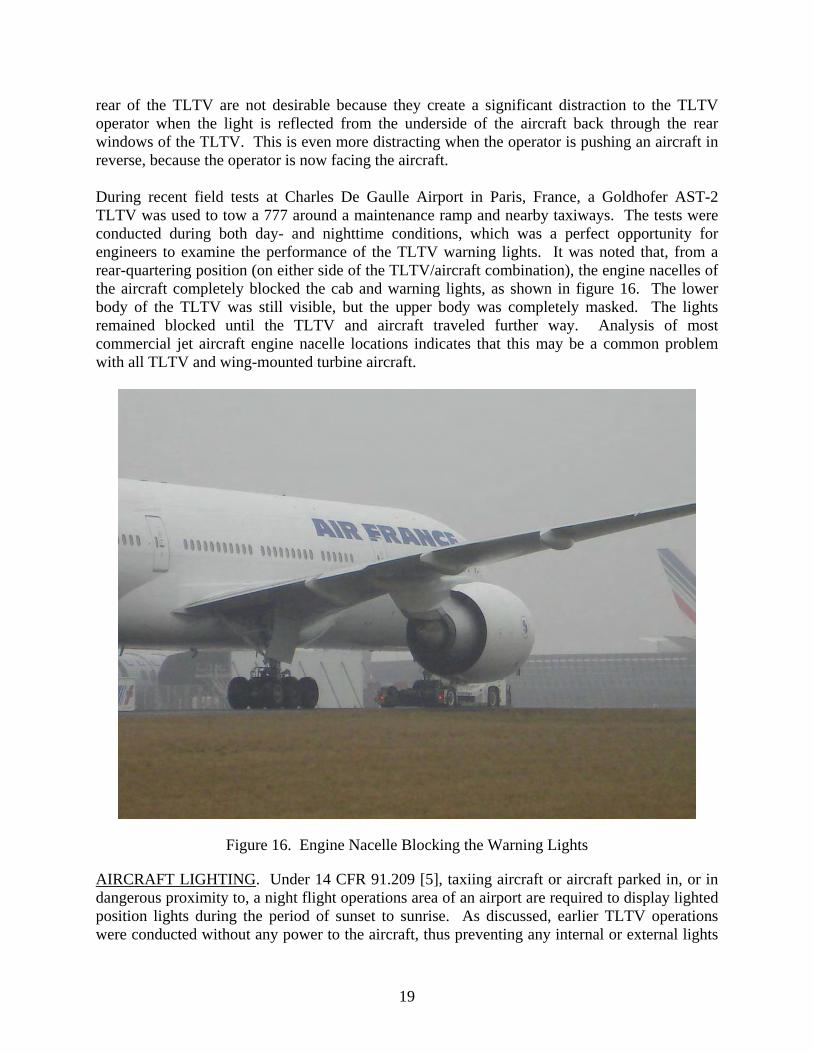
rear of the TLTV are not desirable because they create a significant distraction to the TLTV operator when the light is reflected from the underside of the aircraft back through the rear windows of the TLTV. This is even more distracting when the operator is pushing an aircraft in reverse, because the operator is now facing the aircraft. During recent field tests at Charles De Gaulle Airport in Paris, France, a Goldhofer AST-2 TLTV was used to tow a 777 around a maintenance ramp and nearby taxiways. The tests were conducted during both day- and nighttime conditions, which was a perfect opportunity for engineers to examine the performance of the TLTV warning lights. It was noted that, from a rear-quartering position (on either side of the TLTV/aircraft combination), the engine nacelles of the aircraft completely blocked the cab and warning lights, as shown in figure 16. The lower body of the TLTV was still visible, but the upper body was completely masked. The lights remained blocked until the TLTV and aircraft traveled further way. Analysis of most commercial jet aircraft engine nacelle locations indicates that this may be a common problem with all TLTV and wing-mounted turbine aircraft.
Figure 16. Engine Nacelle Blocking the Warning Lights
AIRCRAFT LIGHTING. Under 14 CFR 91.209 [5], taxiing aircraft or aircraft parked in, or in dangerous proximity to, a night flight operations area of an airport are required to display lighted position lights during the period of sunset to sunrise. As discussed, earlier TLTV operations were conducted without any power to the aircraft, thus preventing any internal or external lights
19

from being energized during nighttime operations. With the requirement to have the aircraft manned, internal and external lighting can easily be turned on while the aircraft is being towed by a TLTV. For most of today’s commercial fleet, this includes interior cabin lights, navigation lights, red beacons, and if equipped, logo lights. Typically, these aircraft will not illuminate their taxi or landing lights as it would seriously blind the TLTV operator who would be directly in front of these light sources. During the field tests at Charles De Gaulle, it was noted that not using the taxi or landing lights made it very hard to see the aircraft from a distance, as shown in figure 17. While it is not the intent of the taxi or landing light, their illumination on the ground in front of the aircraft creates a large illuminated area that, when seen alongside the navigation, cabin, red beacon, and logo lights, collectively makes the aircraft much easier to see on the airport at night, as shown in figure 18. This may be why ATC and other pilots have reported that towed aircraft are hard to see at night, despite the fact they have their other lights illuminated.
Figure 17. A TLTV Towing a 777 at Night
20

Photograph by Stewart Andrew, as posted on Airliners.net
Figure 18. Aircraft With Taxi Lights On
CONCLUSIONS OF TLTV AND AIRCRAFT CONSPICUITY. After completing the initial investigation into TLTV conspicuity issues, several deficiencies that should be addressed to increase the safety of TLTV operations were identified. Aircraft tractors have historically operated only on apron or ramp areas, but new TLTVs are a new generation of tractor that require access to the airport operations area. Their conspicuity is very important to aviation safety. The investigation has identified deficiencies in the following areas. • Paint Color—TLTVs are typically painted in white or light gray colors, which are hard to
see at long distances against concrete or bleached asphalt pavement surfaces, especially when not towing an aircraft.
• Lighting—TLTVs have a unique operational requirement that makes roof-mounted
lighting very difficult to implement without having negative impacts on the TLTV driver or the pilot in the cockpit of the aircraft.
• Aircraft Lighting—The geometry of a TLTV coupled with an aircraft creates a unique
situation where the aircraft is not able to illuminate its nose gear-mounted taxi lights without blinding the TLTV driver, which makes the aircraft less conspicuous.
Researchers were able to make the following conclusions that may increase the conspicuity of a TLTV when towing an aircraft on the airport operations area.
21

22
• Conspicuity may be increased by painting the TLTV in a bright color, such as red, as it may offer improved conspicuity over a TLTV that is painted white or gray.
• The use of reflective tape along the bottom edges of the TLTV body may increase
conspicuity during nighttime conditions. This would involve retrofitting a TLTV with bands of 6- or 8-inch-wide reflective white sheeting around the lower panels of the vehicle.
• TLTVs may be fitted with additional warning lights to provide supplemental coverage.
Of particular interest is the placement of lights on the rear of the TLTV that may solve the masking by the engine nacelle issue identified in France, and increase the TLTV’s conspicuity from the full 360 degrees without moving the warning lights to the roof of the TLTV.
REFERENCES
1. Boeing Service Letter ATA: 0910-00, “Towbarless Towing,” April 6, 2007. 2. Boeing Document D6-56872, “Towbarless Towing Vehicle Assessment Criteria,”
April 6, 2007. 3. Goldhofer Airport Technology, “Towing Tests With B767 and AST-2,” March 12, 1999. 4. FAA Advisory Circular 150/5210-5C, “Painting, Marking and Lighting of Vehicles Used
on an Airport,” August 31, 2007. 5. Title 14 Code of Federal Regulations 91.209.

APPENDIX A—EXCERPTS FROM BOEING DOCUMENT D6-56872
4. Nose Gear Towbarless Tow Load Limit
4.1. Summary The tow loads shown in Table 4.1-1 are the recommended towbarless tow load limits during maximum (or emergency) vehicle acceleration and braking both for test and in-service operations. Section (6.3.3) outlines the test and evaluation procedure to determine if the TLTV/airplane model combination meets the nose gear tow load test criteria. Test results will need to be compared to these tow load limits as part of the evaluation procedure. If any tow loads induced during maximum (emergency) TLTV braking and acceleration exceed the values of Table 4.1-1, the TLTV must be modified (e.g., load limiters, tractive and braking force governors) to reduce the loads. An acceleration and braking example is presented in section (6.5.3). The tow loads applicable for both conventional towbar and towbarless towing are defined in each airplane model’s Facility and Equipment Planning Document (FPD) (see references (b) through (k)). However, TLTV’s tested to date have not been equipped with a structural fuse. Because of this additional concern, TLTV’s must demonstrate through testing that the tow loads of Table 4.1-1 will not be exceeded. Any load limiting system adopted for use on the TLTV must be at least as reliable as the conventional towbar fusepin system. Section (8.2) describes the consequences of applying the airplane brakes.
Airplane (includes all derivative
Models except as noted) Tow Load Limit
(lbs-force) 727 737 747 757 767 777 787
23,000 18,000 85,000 31,000 42,000 64,000 44,000
DC-9-10 DC-9-20 thru -50
MD-80/90/717-299 DC-10-10/-15 DC10-30/-40
MD11
15,000 15,000 15,000 44,000 51,000 51,200
±
±
Table 4.1-1: Nose Gear Towbarless Tow Load Limit
A-1

A-2
6.3. Test And Evaluation Once calibration has been completed, TLTV tests can proceed. These tests are performed at the two airplane gross weights listed in Table 6.3-1. Slight equipment adjustments may be required at the heavy gross weights in order to “zero” the instrumentation just prior to test.
Airplane Model
Light Gross Weight (lbs-force)
Heavy Gross Weight (lbs-force)
727 (ALL) 103,000 163,000 737-100 thru 737-500 74,000 115,000 737-600 thru 737-900 95,000 130,000
747 (ALL) 375,000 755,000 757 (ALL) 155,000 214,000
767-200/-300 200,000 355,000 767-400 225,000 355,000
777 (ALL) 385,000 480,000 787 (ALL) 277,000 415,000
DC-9-10 49,000 86,000
DC-9-20/30 53,000 – 66,000 95,000 – 105,000 DC-9-40/50/717 63,000 – 69,000 110,000
MD-80 84,000 150,000 MD-90 94,000 158,000
DC-10-10/15 230,000 400,000 DC-10-30/40 235,000 530,000
MD-11 280,000 570,000
Table 6.3-1: Airplane Test Weight Requirements A. The actual test weight must be within ±5% of the gross weights listed in Table 6.3-1.
Ballast should be positioned to achieve a center of gravity (c.g.) that is typical of in-service conditions for the given gross weight. In cases where the above heavy gross weights can not be met, refer to Appendix A.

APPENDIX B—AST-2 TRACTOR SPECIFICATIONS
B-1/B-2


![docs.openinfo.gov.bc.cadocs.openinfo.gov.bc.ca/Response_Package_TRA-2016-60134.pdf · Notlce aqd Or"r does not operat]on of the with identifed deføctg. Non-compliance *4th thls NotTee](https://img.dokumen.tips/doc/110x75/5ed849fc724c4f68db5ffe73/docs-notlce-aqd-orr-does-not-operaton-of-the-with-identifed-defctg-non-compliance.jpg)
![TECHNICAL BULLETIN [ 1 / 50 ]...MARS TOHKEN SOLUTION CO.,LTD TLMS-3500RV Not necessary *5 GT01-C30R2-25P *1 THLS-6712 AD-6712 Included with a barcode reade r THLS-6800 An adapter …](https://img.dokumen.tips/doc/110x75/611bf7be902ee4188e0b11e3/technical-bulletin-1-50-mars-tohken-solution-coltd-tlms-3500rv-not-necessary.jpg)