Embed Size (px)
Citation preview

ISET GOLDEN JUBILEE SYMPOSIUM Indian Society of Earthquake Technology
Department of Earthquake Engineering Building IIT Roorkee, Roorkee
October 20-21, 2012
Paper No. D009
EVALUATION OF STRUCTURAL STABILITY OF AN EXISTING GRAVITY DAM BY FINITE ELEMENT METHOD
BY APPLYING PSEUDODYNAMIC APPROACH
Rizwan Ali1, Hanumanthappa M.S.2, Shyamli Paswan3, A.K.Ghosh4 and S.Govindan 1Research Officer, Central Water and Power Research Station Khadakwasla, Pune-411 024, India,
E-mail : [email protected] 2Senior Research Officer, Central Water and Power Research Station Khadakwasla, Pune-411 024, India
3Assistant Research Officer, Central Water and Power Research Station Khadakwasla, Pune-411 024, India 4Chief Research Officer, Central Water and Power Research Station Khadakwasla, Pune-411 024, India
5Additional Director , Central Water and Power Research Station Khadakwasla, Pune-411 024, India
ABSTRACT
Stress analysis of concrete gravity dam to assess its structural stability involves complexity, if dynamic loads under earthquake conditions need to be simulated. Pseudo static approach of analysis, using constant seismic coefficients, is usually adopted for carrying out such analysis using general purpose FEM Softwares. However this approach can be too conservative and may yield very high stresses in the dam body. A further refined approach in simulating earthquake load is Pseudo dynamic analysis where variation in applied seismic coefficients from top to the base of the dam is adopted as per IS:1893-1984,2002 guidelines. In Pseudo Dynamic analysis, inertia effect of reservoir water is considered in the form of added mass by Westergaard approach and inertia of dam body is considered by applying equivalent concentrated loads at the centroid of elements in the central region of the dam body with a variation of seismic coefficients from 1.5times the value at the top and gradually reducing to zero at the base. Present paper discusses a case study undertaken, to evaluate the structural stability of 20.70 m high spillway section of Karanja concrete gravity dam situated in seismic zone II in Karnataka,India. An account of the two dimensional Static as well as Pseudo dynamic stress analysis by finite element method to assess the effect of seismic loads on stability of the spillway block has been presented by utilizing general purpose Finite Element Software SOLVIA ver.99.0. The spillway section along with the foundation has been discretized into 456 nine noded iso-parametric elements and load conditions have been adopted as per guidelines of IS 6512:1984. Site specific seismic coefficients based on revised IS1893:2002(Part I) for seismic zone II (αHorizontal =0.108, αVertical=0.0504) have been used and stresses computed under various load combinations have been compared with the permissible stresses and designed strength of concrete. Although a small area near the heel has been found to be under tension with the maximum value of tensile stress being 11.976 kg/cm2,overall tensile as well as compressive stresses developed under static as well as pseudo dynamic load combinations have been found to be within permissible limits of concrete strength. Average factor of safety against shear/sliding at dam-foundation interface as per IS 6512:1984 for all load combinations, has been found to be greater than unity. Key Words: Gravity Dam, Static, Pseudo Static, Pseudo dynamic, Seismic coefficient, Maximum Principal Stress, Factor of safety
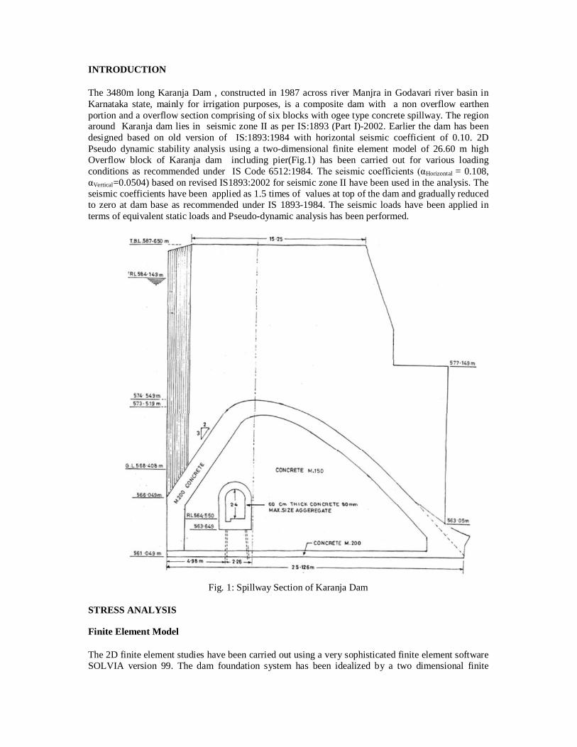
INTRODUCTION The 3480m long Karanja Dam , constructed in 1987 across river Manjra in Godavari river basin in Karnataka state, mainly for irrigation purposes, is a composite dam with a non overflow earthen portion and a overflow section comprising of six blocks with ogee type concrete spillway. The region around Karanja dam lies in seismic zone II as per IS:1893 (Part I)-2002. Earlier the dam has been designed based on old version of IS:1893:1984 with horizontal seismic coefficient of 0.10. 2D Pseudo dynamic stability analysis using a two-dimensional finite element model of 26.60 m high Overflow block of Karanja dam including pier(Fig.1) has been carried out for various loading conditions as recommended under IS Code 6512:1984. The seismic coefficients (αHorizontal = 0.108, αVertical=0.0504) based on revised IS1893:2002 for seismic zone II have been used in the analysis. The seismic coefficients have been applied as 1.5 times of values at top of the dam and gradually reduced to zero at dam base as recommended under IS 1893-1984. The seismic loads have been applied in terms of equivalent static loads and Pseudo-dynamic analysis has been performed.
Fig. 1: Spillway Section of Karanja Dam
STRESS ANALYSIS Finite Element Model The 2D finite element studies have been carried out using a very sophisticated finite element software SOLVIA version 99. The dam foundation system has been idealized by a two dimensional finite
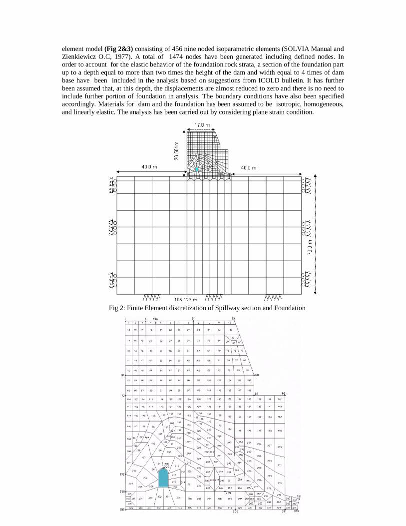
element model (Fig 2&3) consisting of 456 nine noded isoparametric elements (SOLVIA Manual and Zienkiewicz O.C, 1977). A total of 1474 nodes have been generated including defined nodes. In order to account for the elastic behavior of the foundation rock strata, a section of the foundation part up to a depth equal to more than two times the height of the dam and width equal to 4 times of dam base have been included in the analysis based on suggestions from ICOLD bulletin. It has further been assumed that, at this depth, the displacements are almost reduced to zero and there is no need to include further portion of foundation in analysis. The boundary conditions have also been specified accordingly. Materials for dam and the foundation has been assumed to be isotropic, homogeneous, and linearly elastic. The analysis has been carried out by considering plane strain condition.
Fig 2: Finite Element discretization of Spillway section and Foundation
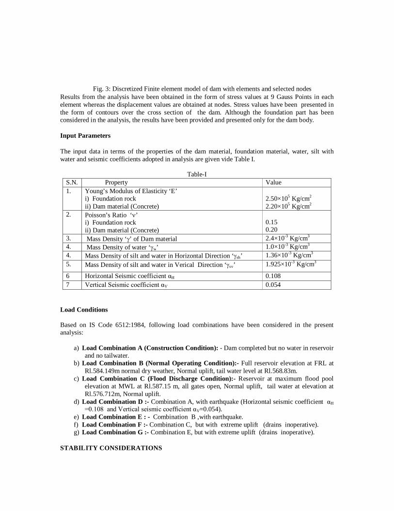
Results from the analysis have been obtained in the form of stress values at 9 Gauss Points in each element whereas the displacement values are obtained at nodes. Stress values have been presented in the form of contours over the cross section of the dam. Although the foundation part has been considered in the analysis, the results have been provided and presented only for the dam body. Input Parameters The input data in terms of the properties of the dam material, foundation material, water, silt with water and seismic coefficients adopted in analysis are given vide Table I.
Table-I S.N. Property Value 1. Young’s Modulus of Elasticity ‘E’
i) Foundation rock ii) Dam material (Concrete)
2.50×10⁵ Kg/cm2 2.20×10⁵ Kg/cm2
2. Poisson’s Ratio ‘’ i) Foundation rock ii) Dam material (Concrete)
0.15 0.20
3. Mass Density ‘’ of Dam material 2.4×10⁻³ Kg/cm3 4. Mass Density of water ‘w’ 1.0×10⁻³ Kg/cm3 4. Mass Density of silt and water in Horizontal Direction ‘sh’ 1.36×10⁻³ Kg/cm3 5. Mass Density of silt and water in Verical Direction ‘sv’ 1.925×10⁻³ Kg/cm3
6 Horizontal Seismic coefficient αH 0.108 7 Vertical Seismic coefficient αV 0.054
Load Conditions Based on IS Code 6512:1984, following load combinations have been considered in the present analysis:
a) Load Combination A (Construction Condition): - Dam completed but no water in reservoir and no tailwater.
b) Load Combination B (Normal Operating Condition):- Full reservoir elevation at FRL at Rl.584.149m normal dry weather, Normal uplift, tail water level at Rl.568.83m.
c) Load Combination C (Flood Discharge Condition):- Reservoir at maximum flood pool elevation at MWL at Rl.587.15 m, all gates open, Normal uplift, tail water at elevation at Rl.576.712m, Normal uplift.
d) Load Combination D :- Combination A, with earthquake (Horizontal seismic coefficient αH =0.108 and Vertical seismic coefficient αV=0.054).
e) Load Combination E : - Combination B ,with earthquake. f) Load Combination F :- Combination C, but with extreme uplift (drains inoperative). g) Load Combination G :- Combination E, but with extreme uplift (drains inoperative).
STABILITY CONSIDERATIONS
Fig. 3: Discretized Finite element model of dam with elements and selected nodes
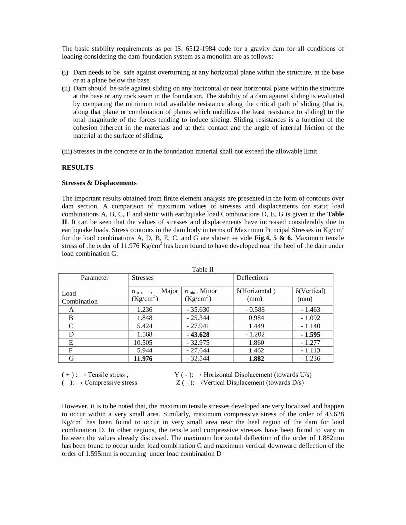
The basic stability requirements as per IS: 6512-1984 code for a gravity dam for all conditions of loading considering the dam-foundation system as a monolith are as follows: (i) Dam needs to be safe against overturning at any horizontal plane within the structure, at the base
or at a plane below the base. (ii) Dam should be safe against sliding on any horizontal or near horizontal plane within the structure
at the base or any rock seam in the foundation. The stability of a dam against sliding is evaluated by comparing the minimum total available resistance along the critical path of sliding (that is, along that plane or combination of planes which mobilizes the least resistance to sliding) to the total magnitude of the forces tending to induce sliding. Sliding resistances is a function of the cohesion inherent in the materials and at their contact and the angle of internal friction of the material at the surface of sliding.
(iii) Stresses in the concrete or in the foundation material shall not exceed the allowable limit. RESULTS Stresses & Displacements The important results obtained from finite element analysis are presented in the form of contours over dam section. A comparison of maximum values of stresses and displacements for static load combinations A, B, C, F and static with earthquake load Combinations D, E, G is given in the Table II. It can be seen that the values of stresses and displacements have increased considerably due to earthquake loads. Stress contours in the dam body in terms of Maximum Principal Stresses in Kg/cm2 for the load combinations A, D, B, E, C, and G are shown in vide Fig.4, 5 & 6. Maximum tensile stress of the order of 11.976 Kg/cm2 has been found to have developed near the heel of the dam under load combination G.
Table II Parameter Load Combination
Stresses Deflections
σmax , Major (Kg/cm2 )
σmin , Minor (Kg/cm2 )
δ(Horizontal ) (mm)
δ(Vertical) (mm)
A 1.236 - 35.630 - 0.588 - 1.463 B 1.848 - 25.344 0.984 - 1.092 C 5.424 - 27.941 1.449 - 1.140 D 1.568 - 43.628 - 1.202 - 1.595 E 10.505 - 32.975 1.860 - 1.277 F 5.944 - 27.644 1.462 - 1.113 G 11.976 - 32.544 1.882 - 1.236 ( + ) : → Tensile stress , Y ( - ): → Horizontal Displacement (towards U/s) ( - ): → Compressive stress Z ( - ): →Vertical Displacement (towards D/s) However, it is to be noted that, the maximum tensile stresses developed are very localized and happen to occur within a very small area. Similarly, maximum compressive stress of the order of 43.628 Kg/cm2 has been found to occur in very small area near the heel region of the dam for load combination D. In other regions, the tensile and compressive stresses have been found to vary in between the values already discussed. The maximum horizontal deflection of the order of 1.882mm has been found to occur under load combination G and maximum vertical downward deflection of the order of 1.595mm is occurring under load combination D

.
Fig. 4. Maximum Principal Stress Contours for Loading Condition A & D
Fig. 5. Maximum Principal Stress Contours for Loading Condition B & E
Loading Condition B Loading Condition E
Loading Condition A Loading Condition D
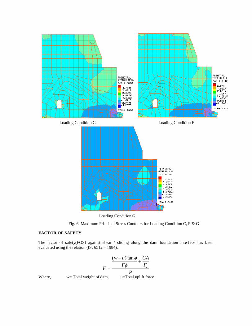
FACTOR OF SAFETY The factor of safety(FOS) against shear / sliding along the dam foundation interface has been evaluated using the relation (IS: 6512 – 1984).
PFCA
Fuw
F c
tan)(
Where, w= Total weight of dam, u=Total uplift force
Loading Condition C Loading Condition F
Loading Condition G
Fig. 6. Maximum Principal Stress Contours for Loading Condition C, F & G
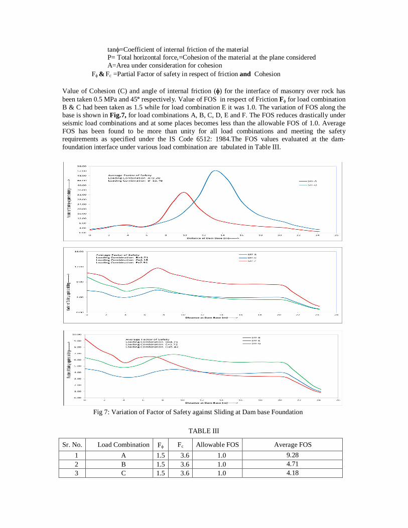
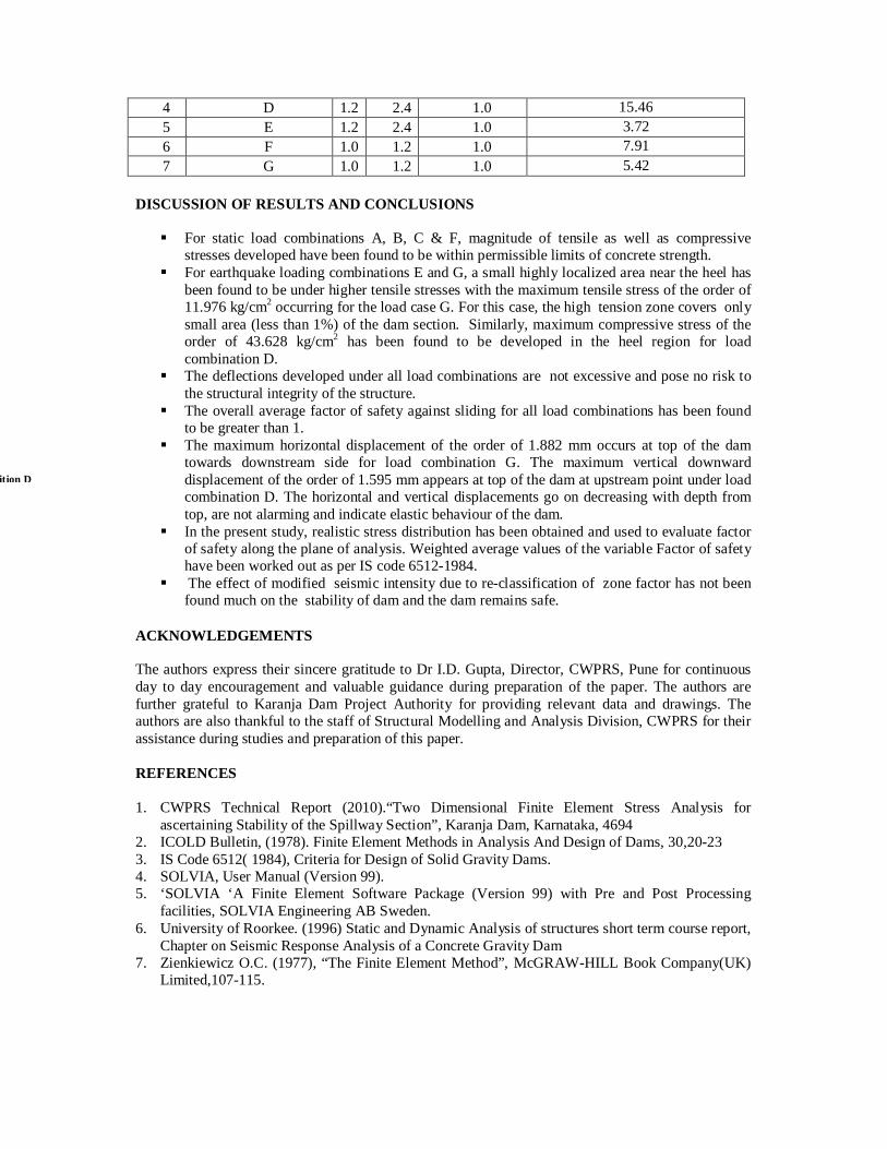
tan=Coefficient of internal friction of the material P= Total horizontal force,=Cohesion of the material at the plane considered A=Area under consideration for cohesion F & Fc =Partial Factor of safety in respect of friction and Cohesion Value of Cohesion (C) and angle of internal friction () for the interface of masonry over rock has been taken 0.5 MPa and 45º respectively. Value of FOS in respect of Friction F for load combination B & C had been taken as 1.5 while for load combination E it was 1.0. The variation of FOS along the base is shown in Fig.7, for load combinations A, B, C, D, E and F. The FOS reduces drastically under seismic load combinations and at some places becomes less than the allowable FOS of 1.0. Average FOS has been found to be more than unity for all load combinations and meeting the safety requirements as specified under the IS Code 6512: 1984.The FOS values evaluated at the dam-foundation interface under various load combination are tabulated in Table III.
TABLE III
Sr. No. Load Combination F Fc Allowable FOS Average FOS 1 A 1.5 3.6 1.0 9.28 2 B 1.5 3.6 1.0 4.71 3 C 1.5 3.6 1.0 4.18
Fig 7: Variation of Factor of Safety against Sliding at Dam base Foundation
DISCUSSION OF RESULTS AND CONCLUSIONS For static load combinations A, B, C & F, magnitude of tensile as well as compressive
stresses developed have been found to be within permissible limits of concrete strength. For earthquake loading combinations E and G, a small highly localized area near the heel has
been found to be under higher tensile stresses with the maximum tensile stress of the order of 11.976 kg/cm2 occurring for the load case G. For this case, the high tension zone covers only small area (less than 1%) of the dam section. Similarly, maximum compressive stress of the order of 43.628 kg/cm2 has been found to be developed in the heel region for load combination D.
The deflections developed under all load combinations are not excessive and pose no risk to the structural integrity of the structure.
The overall average factor of safety against sliding for all load combinations has been found to be greater than 1.
The maximum horizontal displacement of the order of 1.882 mm occurs at top of the dam towards downstream side for load combination G. The maximum vertical downward displacement of the order of 1.595 mm appears at top of the dam at upstream point under load combination D. The horizontal and vertical displacements go on decreasing with depth from top, are not alarming and indicate elastic behaviour of the dam.
In the present study, realistic stress distribution has been obtained and used to evaluate factor of safety along the plane of analysis. Weighted average values of the variable Factor of safety have been worked out as per IS code 6512-1984.
The effect of modified seismic intensity due to re-classification of zone factor has not been found much on the stability of dam and the dam remains safe.
ACKNOWLEDGEMENTS The authors express their sincere gratitude to Dr I.D. Gupta, Director, CWPRS, Pune for continuous day to day encouragement and valuable guidance during preparation of the paper. The authors are further grateful to Karanja Dam Project Authority for providing relevant data and drawings. The authors are also thankful to the staff of Structural Modelling and Analysis Division, CWPRS for their assistance during studies and preparation of this paper. REFERENCES 1. CWPRS Technical Report (2010).“Two Dimensional Finite Element Stress Analysis for
ascertaining Stability of the Spillway Section”, Karanja Dam, Karnataka, 4694 2. ICOLD Bulletin, (1978). Finite Element Methods in Analysis And Design of Dams, 30,20-23 3. IS Code 6512( 1984), Criteria for Design of Solid Gravity Dams. 4. SOLVIA, User Manual (Version 99). 5. ‘SOLVIA ‘A Finite Element Software Package (Version 99) with Pre and Post Processing
facilities, SOLVIA Engineering AB Sweden. 6. University of Roorkee. (1996) Static and Dynamic Analysis of structures short term course report,
Chapter on Seismic Response Analysis of a Concrete Gravity Dam 7. Zienkiewicz O.C. (1977), “The Finite Element Method”, McGRAW-HILL Book Company(UK)
Limited,107-115.
4 D 1.2 2.4 1.0 15.46 5 E 1.2 2.4 1.0 3.72 6 F 1.0 1.2 1.0 7.91 7 G 1.0 1.2 1.0 5.42
For load condition D