Embed Size (px)
Citation preview

Evaluation of Dust Collector Systems to Optimize Performance
Andy WinstonGE Energy

Why talk about dust collection?“The accompanying phenomenon of comminution, handling and processing … the material components which finally form Portland cement is the generation of dust .”
- from Duda’s Cement Data-Book
© 2010, General Electric Company
2

2000 mtpd = approx. 1400 kg/min of cement production
Typical 2000 mtpd cement plant
2610 kg/min 1400 kg/min
= 1.9 kg of dust collected for every kg of cement produced!
© 2010, General Electric Company
3

Major components of a dust collection system
© 2010, General Electric Company
DuctworkFan
Dust Removal SystemVent Hood
Dust Collector

Basic concept of a dust collection system
Ideally, it’s not a dust collect ion system,it’s a dust containment or cont rol system
© 2010, General Electric Company
5

Ultimate goal of a dust ventilation system
Provide maximum dust control and containment with a minimumof dust collection
© 2010, General Electric Company
6

The volumetric flow rate of air or gas per unit of time
Usual units are:• Cubic feet per minute (cfm)• Cubic meters per minute (m3/min)• Cubic meters per hour (m3/h)
Air flow or gas flow
© 2010, General Electric Company
7

Major components of a dust ventilation system
© 2010, General Electric Company
8
Vent Hood
Hood design
© 2010, General Electric Company
9
Vent points and hoods are probably the most overlooked component of a dust control system

For enclosure type hoods:
Q = V x A
Q = Ventilation Airflow Rate (cfm)
V = Capture Velocity (fpm)
A = Total Open Area on Enclosure (sq. ft .)
© 2010, General Electric Company
10

BetterDesign
ImprovedDesign
TypicalDesign
Belt conveyor venting
© 2010, General Electric Company
11

Hood design
© 2010, General Electric Company
12

Hood design
© 2010, General Electric Company
13

Air conveyor venting
© 2010, General Electric Company
14
Bet terDesign
ImprovedDesign
TypicalDesign

Air conveyor venting
© 2010, General Electric Company
15
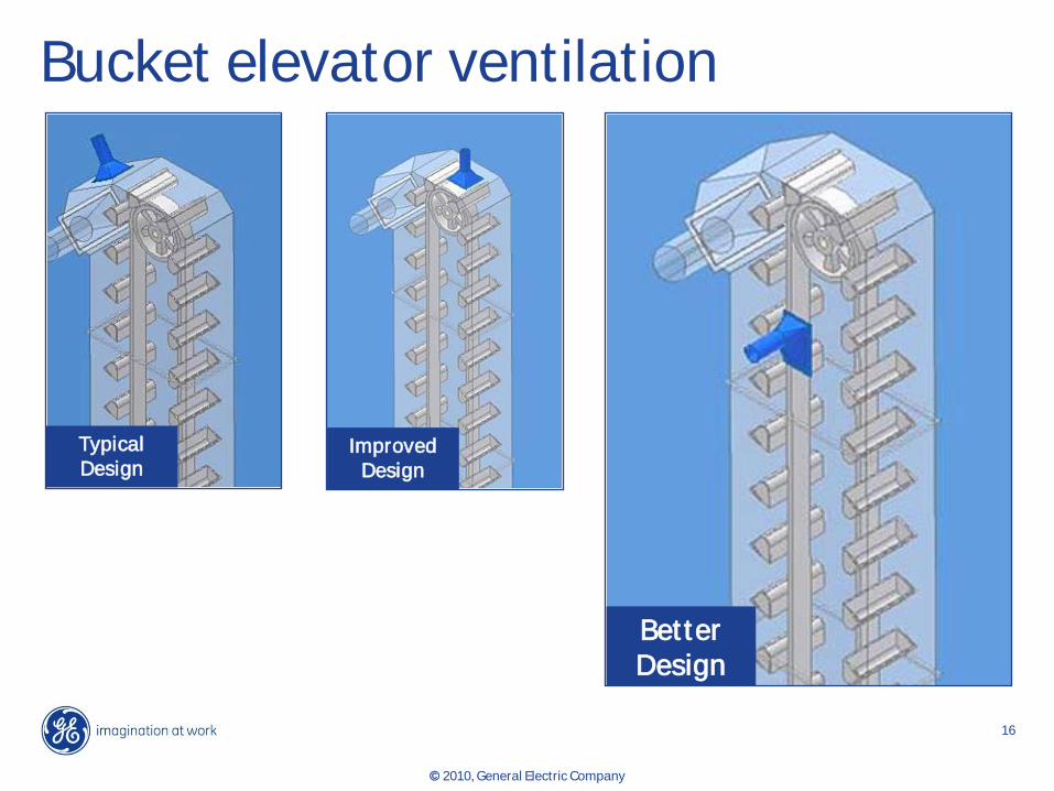
Bucket elevator ventilation
© 2010, General Electric Company
16
ImprovedDesign
TypicalDesign
Bet terDesign

Ball mill ventilation (open end mill)
© 2010, General Electric Company
17
Exhaust Air
Product discharge
Poor design
Exhaust Air
Product discharge
Bet ter design

Hood design – ball mills
© 2010, General Electric Company
18
Extend Mill Hood as High as Possible

Major components of a dust ventilation system
© 2010, General Electric Company
19
Ductwork

Air or gas flow in a duct
Q = V x A
Q = Air or Gas Flow (cfm)
V = Transport Velocity in Duct (fpm)
A = Cross-Sectional Area of Duct (sq. ft .)
© 2010, General Electric Company
20

Duct design
© 2010, General Electric Company
21
Acceptable Recommended Acceptable Acceptable
Recommended Recommended Recommended Recommended
Avoid Avoid Avoid Avoid

Duct design
© 2010, General Electric Company
22

Duct design
© 2010, General Electric Company
23

Equal Areas
Blast Gate Damper Modificat ion
Ductwork balancing
© 2010, General Electric Company
24
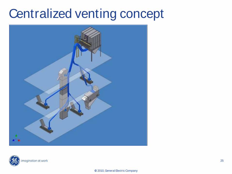
Centralized venting concept
© 2010, General Electric Company
25

Decentralized point venting
© 2010, General Electric Company
26

Major components of a dust ventilation system
© 2010, General Electric Company
27
Dust Collector

Type of filter Maximum recommendedcleaning system air-to-cloth rat io
Shaker 3.0Reverse Air 2.0Pulse-Jet :A. Cylindrical Filter Bags 6.0B. Pleated Filters (Non-Paper Media) 3.5C. Pleated Filters (Paper Media) 2.0
Plenum Pulse 4.0
Air-to-cloth ratio
© 2010, General Electric Company
28

Can velocityIn a pulse jet dust collector with the filter elements suspended from the tubesheet, can velocity is the upward air stream speed passing between the filters calculated at the horizontal cross-sectional plane of the collector housing at the bottom of the filters
© 2010, General Electric Company
29

Photohelic® gaugeAn instrument used to measure and control baghouse differential pressure; having adjustable set points that can be used for starting and stopping the baghouse valve-firing timer board, to maintain a desired range of operating differential pressure.
© 2010, General Electric Company
30

Major components of a dust ventilation system
© 2010, General Electric Company
31
Fan

Cubic Feet per minute (CFM)
Stat ic Pressure
12” } Out let Duct
1” } Pickup Hood
11”
Baghouse + Media
5”
Ductwork to Baghouse
Q1
SP = Constant x Q2
System curve
© 2010, General Electric Company
32

System and fan curves
© 2010, General Electric Company
33
Pres
sure
(P)
Fan
Desired
BaghousePressure
SystemPressure
Flow Rate (Q)

System effect
© 2010, General Electric Company
34
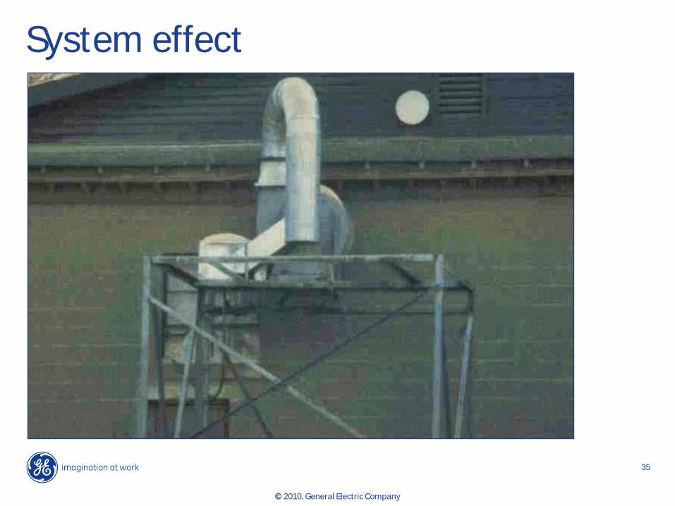
System effect
© 2010, General Electric Company
35

Make sure your systems are:
• Maximizing dust control and containment
• While minimizing dust collection
In conclusion
© 2010, General Electric Company
36