Embed Size (px)
Citation preview
Report No. CDOT-2006-16 Final Report
EVALUATION OF DEBRIS FLOW REMOVAL PROTOCOL, MITIGATION METHODS, AND DEVELOPMENT OF A FIELD DATA SHEET Paul M. Santi, Nathan C. Soule, Rebecca J. Brock Colorado School of Mines
December 2006 COLORADO DEPARTMENT OF TRANSPORTATION RESEARCH BRANCH

The contents of this report reflect the views of the
author(s), who is(are) responsible for the facts and
accuracy of the data presented herein. The contents
do not necessarily reflect the official views of the
Colorado Department of Transportation or the
Federal Highway Administration. This report does
not constitute a standard, specification, or regulation.

Technical Report Documentation Page 1. Report No. CDOT-2006-16
2. Government Accession No.
3. Recipient's Catalog No.
5. Report Date December 2006
4. Title and Subtitle EVALUATION OF DEBRIS FLOW REMOVAL PROTOCOL, MITIGATION METHODS, AND DEVELOPMENT OF A FIELD DATA SHEET
6. Performing Organization Code
7. Author(s) Paul M. Santi, Nathan C. Soule, Rebecca J. Brock
8. Performing Organization Report No. CDOT-2006-16
10. Work Unit No. (TRAIS)
9. Performing Organization Name and Address Colorado School of Mines CSM Office of Research 1500 Illinois St. Golden, Colorado, 80401
11. Contract or Grant No.
13. Type of Report and Period Covered
12. Sponsoring Agency Name and Address Colorado Department of Transportation - Research 4201 E. Arkansas Ave. Denver, CO 80222 14. Sponsoring Agency Code
15. Supplementary Notes Prepared in cooperation with the Colorado Department of Transportation, Materials and Geotechnical Branch, Rockfall Program
16. Abstract The purpose of this report is to discuss protocol for the removal of debris on roadways, maintaining worker safety, recording of key information for future use, and selecting feasible mitigation measures to protect the roadway from debris-flow hazards. Collection of data during removal of debris from roadways will provide a database that may assist in ranking and/or mitigating roadways with frequent debris-flow hazards.
A debris flow, sometimes referred to as a mudslide, is a flowing mixture ranging from watery mud to thick, rocky mud that can carry large items such as boulders, trees, and other debris. Debris flows travel rapidly down slope along drainage channels or stream valleys, often transporting and depositing a large volume of material in areas where the gradient flattens, such as roadways. Because of their relatively high density and viscosity, debris flows can move, and even carry away, vehicles and other objects as large as bridges and railroad cars.
The first part of this report provides a brief description of historic debris flow locations throughout Colorado. The second part details what systems other state and federal agencies have in place to collect information regarding debris flows and unstable slopes. As background research for this report, numerous state and federal agencies were contacted to determine what methods—if any—were in use by other departments of transportation or geological surveys.
17. Keywords mudslides, rocky mud, landslides, unstable slopes, debris-flow hazards, flood discharges, drainage channels
18. Distribution Statement No restrictions. This document is available to the public through the National Technical Information Service Springfield, VA 22161
19. Security Classif. (of this report) Unclassified
20. Security Classif. (of this page) Unclassified
21. No. of Pages 23
22. Price
Form DOT F 1700.7 (8-72) Reproduction of completed page authorized

Evaluation of Debris Flow Removal Protocol, Mitigation Methods, and Development of a Field Data Sheet Final Report to the Colorado Department of Transportation by: Paul M. Santi, Nathan C. Soule, Rebecca J. Brock Colorado School of Mines Colorado School of Mines Colorado Department of Transportation

TABLE OF CONTENTS Page
1. INTRODUCTION AND PURPOSE........................................................................................1
2. BACKGROUND ......................................................................................................................2 2.1. Historic Debris Flow Areas in Colorado ......................................................................2 2.2. Methods Used by Other States and Agencies...............................................................3
3. SAFETY CONSIDERATIONS................................................................................................5 3.1. Observe the Surrounding Area .....................................................................................5 3.2. Observe the Consistency of the Debris.........................................................................6 3.3. Observe the Weather.....................................................................................................6 3.4. Continue to Observe the Flow ......................................................................................6 3.5. Listen for Unusual Sounds............................................................................................6
4. DATA COLLECTION .............................................................................................................7
5. LONG-TERM MITIGATION..................................................................................................9
6. RECOMMENDATIONS........................................................................................................12
7. CONCLUSIONS ....................................................................................................................13
8. REFERENCES .......................................................................................................................14
List of Figures Figure 1 – Schematic drawing of a deflection berm Figure 2 – Schematic drawing of a debris basin Figure 3 – Photograph of a debris rack Figure 4 – Photograph of a ring net Figure 5 – Decision guidelines for choosing a debris-flow mitigation option
List of Tables Table 1 – Debris Flow areas in Colorado Table 2 – Historic Debris Flow areas along I-70
Appendix Appendix A – Debris-Flow Safety Sheet Appendix B – Debris-Flow Field Data Sheet

1
1. INTRODUCTION AND PURPOSE
A debris flow, sometimes referred to as a mudslide, is a flowing mixture ranging from watery mud to thick, rocky mud that can carry large items such as boulders, trees, and other debris. De-bris flows travel rapidly downslope along drainage channels or stream valleys, often transporting and depositing a large volume of material in areas where the gradient flattens, such as roadways. Because of their relatively high density and viscosity, debris flows can move, and even carry away, vehicles and other objects as large as bridges and railroad cars (Miller, 1989).
The purpose of this report is to discuss protocol for removal of debris on roadways, maintaining worker safety, recording of key information for future use, and selecting feasible mitigation measures to protect the roadway from debris-flow hazards. Collection of data during removal of debris from roadways will provide a database that may assist in ranking and/or mitigating road-ways with frequent debris-flow hazards.
Debris flows develop when water rapidly accumulates in the ground. Water may be supplied by rainfall, melting of snow or ice, unsuitable drainage of roads, or by rupture of waterlines. In Colorado, the spring snow-melt and summer rainstorms, coupled with steep topography, initiate numerous debris flows (Highland et al. 1997). Additionally, wildfire, logging, mining, develop-ment, or other disturbance of the watershed may contribute to the occurrence of debris flows. Road cuts and other altered or excavated areas may also flow onto the roadway during storms more readily than natural slopes would (Highland et al. 1997). The areas most prone to move-ment include the mountains and foothills, but landslides have occurred in most areas of the state (DOLA, 2003).
Burial of roadways by debris flows is a common occurrence in Colorado. Interruption of traffic corridors can cause serious delays for emergency personnel, commuters, and commerce. Buried roadways may potentially isolate homeowners and communities by blocking access routes. De-bris flows can cause damage in three ways; direct impact, indirect impact, and flooding (Hunger et al, 1987). Direct impacts are debris flows with a high-discharge and velocity, with violent thrust and impact. This type of impact can destroy objects as large as bridges. Indirect impacts are relatively low discharge and velocity, low impact, large volume flows which are capable of burying the roadway. Liquid after-flow and flood discharges are associated with indirect impacts as they are forced out of depositing surges and have the potential to erode unprotected surfaces and deposit gravel and other small debris (Hunger et al, 1987). Lastly, flooding downstream of the deposition zone has the potential to endanger a relatively large area.
Areas where surface runoff is channeled, such as along roadways and below culverts, are com-mon sites of debris flows and other landslides (Highland et al, 1997). Highway and roadway drainage structures have generally been designed to pass water. These drainage structures may not have adequate capacity for the volume of mud and debris generated by debris flows. The ex-tent of transport and deposition of debris-flow material and the impacts upstream and downstream of defensive measures must be considered for future debris-flow mitigation to avoid creating hazardous conditions elsewhere in the watershed (Hunger et al, 1987).

2
2. BACKGROUND
The first part of this section provides a brief description of historic debris flow locations throughout Colorado. The second part details what systems other state and federal agencies have in place to collect information regarding debris flows and unstable slopes.
2.1. Historic Debris Flow Areas in Colorado
Debris flows have been observed throughout the State of Colorado. The best source (though still quite general) for a statewide inventory of unstable slopes including debris flows is Rogers’ (2003) map: Critical Landslides of Colorado (Noe, P.C., 2006). The map provides a basic ranking system of three tiers which denote the severity of activity and potential impacts. The map highlights a total of sixteen areas with debris flow hazards, which are listed in Table 1.
Table 1 – Major Debris Flow areas in Colorado (from Rogers, 2003)
Tier One Debris Flow Areas -- Highest Severity of Activity and Potential Im-pacts
1 Clear Creek/I-70 Corridor 2 Steep slopes in Douglas County along I-25 south of Castle Rock 3 I-70 Corridor from Vail Pass to just east of Rt. 131 4 Glenwood Springs vicinity 5 Marble town site and vicinity in Gunnison County 6 Ouray and vicinity
7 San Miguel River Corridor from Telluride to Rt. 62 and north on Rt. 62 approxi-mately 5 mi.
Tier Two Debris Flow Areas -- Significant Activity and Potential Impacts
1 Chalk Creek area south of Buena Vista 2 Red Cliff area south of Minturn on Rt. 24
3 Lower reaches and alluvial fans of Arkansas River Tributaries from Salida to west of Cañon City
4 Tributary streams to Big Thompson River 5 Poudre River Corridor on Rt. 14 west of Fort Collins 6 Aspen Mountain Ski area and vicinity 7 Devils Hole Gulch and Wilson Creek area north of Meeker
Tier Three Debris Flow Areas -- Moderate Activity and Local Impacts
1 Sweetwater Creek area northwest of Gypsum 2 Dutch Creek, Coal Creek and Redstone areas south of Carbondale on Rt. 133
Coe et al (2002) produced a field trip guidebook detailing debris flows along the Inter-state 70 and US 6 Corridors between Floyd Hill and Arapahoe Basin Ski Area. The guidebook outlines eight areas that debris flows have historically affected, listed in Table 2.
3
Table 2 – Historic Debris Flow areas along I-70 and US 6 (from Coe et al, 2002)
1 County Road 314 near Aggregate Industries Plant 2 Virginia Canyon in Idaho Springs 3 Ohio Gulch on County Road 310 4 The area between Empire and Georgetown along the north side of I-70
5 Georgetown on the north side of I-70 (the most active debris flow area along the corridor)
6 Brown Gulch just west of Silver Plume 7 Watrous Gulch 8 Arapahoe Basin Ski area
In addition to the debris-flow source areas listed in Table 1 and 2, wildfires throughout the state have generated numerous events in the years following the fires. Recent wild-fires that have had debris flows associated with them include the Missionary Ridge, Coal Seam, Storm King Mountain, Hayman, and Overland Fires. Wildfires greatly increase the potential for debris flows and likely represent the most severe risk for damaging events in the two to three years following the fire, before vegetation is established (Cannon and Gartner, 2005).
2.2. Methods Used by Other States and Agencies
As background research for this report, we contacted numerous state and federal agencies to determine what methods—if any—were in use by other departments of transportation or geological surveys. Washington The Washington Department of Transportation (WSDOT) has the most detailed and ad-vanced system for recognition, classification and mitigation of unstable slope hazards that we found during our research. They began to implement the system about 15 years ago in response to continued losses and litigation due to slope failures (Moses, P.C, 2006). The Unstable Slope Management System (USMS) involves an eight-step process from initial identification to fund allocation and mitigation (WSDOT, 1995). The USMS incorporates all types of slope instability from slope erosion to rockfall rather than main-taining separate databases ranking systems for differing types of failures. The most relevant aspect of the system for the current project is Step 1 which directs the maintenance superintendent in each region to compile a list of unstable slopes. The re-quired information for each unstable slope is given and includes the state route number, milepost distances from the start to end of the area, a preliminary determination of the type of instability (debris flow, rockfall, etc.), the frequency of failure, and the approxi-mate cost of maintenance per year. The information is then used to rate the slope based

4
on an 81-point system similar to CDOT’s revised rockfall management system (Russell, in preparation). Information regarding the location, condition, maintenance and mitigation costs for each unstable slope identified in the state is compiled into a database that is accessible to WSDOT and other state employees. In this way, should an event affect a roadway, WSDOT workers can easily determine whether the failure has been previously identified and what measures have been taken to mitigate the area in the past (Moses, P.C, 2006). Oregon: The Oregon Department of Transportation (ODOT) does not specifically have response guidelines in place for debris flows, however, due to the frequent occurrence of slope failures that affect roadways a debris flow warning system is in place throughout the state (Burns, P.C., 2006). ODOT relies on the Oregon Department of Forestry (ODF) to moni-tor storms and rainfall totals and to locate where debris flows and landslides occur or may occur (Gentry, P.C., 2006). The locations of failures that affect roadways are trans-mitted to ODOT who issues warnings to the general public. The Oregon Department of Geology and Mineral Industries (DOGAMI) developed a landslide inventory worksheet in response to the 1996 and 1997 storm events (Hofmeis-ter, 2000). Through the use of this worksheet and the subsequent database, the locations and conditions of landslides throughout the state are identified and monitored. Idaho: Idaho is similar to Oregon in that an unstable slopes inventory has been developed and locations and conditions of landslides are tracked. A detailed worksheet for locating and describing the landslides was developed by Miller (2003) and many of the components were used in the development of the Data Sheet attached to the current report. Virginia: No system is currently in place for rapid response to debris flows or data collection, but when they do occur, the geotechnical division of the Virginia Department of Transporta-tion typically employs long-term mitigation methods outlined by Reihsen and Harrison (1971) (LeGrande, P.C., 2006). Utah: No system is currently in place to respond to debris flows or to collect and categorize them as they occur (Heppler, P.C., 2006).
FHWA: No system is currently in place to respond to debris flows or to collect information on them as they occur. The FHWA is typically involved in the construction of new roadways rather than maintenance and hazard response (Andersen, P.C., 2006; Rivers, P.C., 2006).

5
3. SAFETY CONSIDERATIONS
Debris flows can happen rapidly, striking with little or no warning, and moving at speeds up to 35 miles per hour (USGS, 2005). They can travel several miles from their sources, over rela-tively gentle gradients, growing in size and momentum as they pick up trees, boulders, cars, and other materials that will cause considerable destruction to anything in the path. When moving, debris flows can resemble masses of wet concrete flowing downslope along channels or stream valleys (Case, 2000). High-speed debris flows may climb valley walls on the outsides of bends, and their momentum may also carry them over obstacles (Miller, 1989). The major hazard to human life from debris flows is from burial or impact by boulders and other debris (Miller, 1989).
It is important to clear roadways and restore travel following debris flows; however, it is also important to understand the danger involved in working in these areas by being aware of the haz-ards created by debris flow and flooding, and signs that another debris flow may occur. Some “symptoms” of a debris flow do not provide much lead-time for evacuation, and in some cases there is no warning.
If a debris flow occurs before a proper evacuation of workers and equipment is possible, the workers should quickly move uphill, out of the canyon, and away from the path of the debris flow (CDC, 2003). If escape is not possible, the National Disaster Education Coalition (NDEC, 1996) recommends the best protection is to curl into a tight ball and protect the head. The con-struction team should have an internal warning system, such as whistles or other loud noises to alert others of a possible debris flow approaching. All occupants of the area should be familiar with evacuation procedures, emergency escape routes or paths, and personal protection for fast approaching debris flows.
In addition to the danger associated with rapid debris flow, slow moving, or creeping, debris flows pose danger as well. Measures should be taken to prevent starting a slow-moving, or local-ized landslide by controlling the excavation procedure when removing debris-flow material from a roadway. Excavations should generally be less than 5-feet high, and be in accordance with OSHA guidelines (29 CFR Part 1926). In order to prevent localized instabilities from steep, un-supported slopes in large debris flows, removal of thick deposits should be conducted in a widespread manner, removing material from the edges and upper portions then proceeding up-slope. The contractor should set up a stake line above the limits of excavation, and observe the stakes frequently for signs of movement.
Debris flows are unpredictable and fast moving events, but careful observation of the following conditions will help identify imminent flows. These safety considerations are summarized in the attached sheet “Debris-Flow Safety” (Appendix A), which is intended for wide distribution among field personnel.
3.1. Observe the Surrounding Area Debris flows can be violent events capable of damaging bridges, rupturing utility lines, and causing erosion beneath roadways. Care must be taken to ensure bridges are stable, the roadway is solid, and there are no live electrical wires, gas or water leaks before al-lowing construction vehicles and personnel to occupy the area. Additionally, adjacent

6
drainage channels may contain debris or floodwater that may affect staging areas, hauling routes, or emergency evacuation.
Location selection of headquarters and staging areas should be carefully planned. These areas should be located away from “active” channels and canyon mouths that debris may potentially exit and head for low ground. Preferential worksite areas are on higher ground, between canyon mouths, with the safest access routes considered.
3.2. Observe the Consistency of the Debris Fresh debris is initially very wet, and unstable, quick conditions may be present. To avoid trapped machinery and workers, this material should not be walked or driven on. Additionally, as this material is very fresh, it is possible that more material may be on the way.
3.3. Observe the Weather Debris flows develop when water rapidly accumulates in the ground; therefore it is im-portant to identify continued sources of water such as rainfall, snowmelt, irrigation systems, or pipe or canal leaks. If present, additional events may occur. The likelihood of a debris flow tends to decline after a day or more of dry weather, although deep-seated landslides may still occur several days after heavy rain (USGS, 2005). Caution should be taken if rainfall resumes: sudden bursts of rain may be particularly dangerous (Highland et al., 1997). If the source of the debris flow is spring snowmelt, a debris flow may be more likely to initiate in warmer weather. If the source of the water is man-made, meas-ures should be taken to control the water prior to removal of the debris.
3.4. Continue to Observe the Flow Observations of any water running in the channel may give an indication of approaching debris. A change in the water from clear to muddy may indicate landslide activity up-stream (Highland et al., 1997). An appearance of increased flow, or pulses in the flow, may indicate that the debris flow is still occurring. Alternatively, a sudden decrease in flow may indicate plugging or damming of the channel upstream. A flooding or bursting of this debris dam could suddenly release destructive flood water or debris flow (High-land et al., 1997). Any adverse observations of the stream flow should initiate an evacuation of the site until the upstream channel can be evaluated.
3.5. Listen for Unusual Sounds Cracking trees, falling boulders, and movement of other debris materials may indicate a hazardous condition initiating upstream. This material can be transported downslope long distances in the form of debris flows (Highland et al., 1997). Noises from these events should raise awareness that another debris flow may be traveling downstream. Workers should immediately evacuate to an uphill location (away from the drainage channel) until either the debris event passes or the noises abate.
7
4. DATA COLLECTION
This section explains the components and procedures that are presented in the attached Debris Flow Data Sheet (Appendix B). The primary method through which information will be col-lected is through the use of the Data Sheet which is intended to be completed to the extent possible by the field personnel who first respond to the incident and/or the supervisor overseeing the clean up and mitigation. Some information may not be known by field personnel, therefore an “Office Use” form requests information on landownership, rainfall, and basin conditions. The information requested on the Data Sheet was included based on the authors’ experience, and from Washington’s DOT, and Oregon’s and Idaho’s Landslide Inventory programs (Hofmeister, 2000; Miller, 2003; WSDOT, 1995). Bookkeeping information includes data such as the date of first observation, date of the event if known, the name of the on-site employee and their CDOT district number, and the storage loca-tion of any photos taken of the debris flow. The second section asks for information regarding the location of the event and the characteristics of the roadway on which it occurred. Highway route number, milepost, posted speed limit and estimated sight distance will be useful for rank-ing areas for future mitigative action. Areas with high recurrence intervals, high speed limits and/or limited sight distances will likely be targets for early preventive measures. For purposes of statistical records and insurance, the Data Sheet also provides space to note whether the event involved vehicle accidents. The third section of the Data Sheet is for information pertaining to the debris flow and the sur-rounding affected area. Data including the size and type of any culverts or mitigation measures present will help to track the effectiveness of them and provide guidance on whether additional measures should be taken. One of the most important pieces of information from a response and mitigation standpoint is the volume of material generated by the debris flow. The volume pro-duced by the flow affects the size and duration of the clean up effort, which in turn affects possible traffic delays. While the volume of one debris flow does not necessarily indicate that future events from the same drainage will be of similar magnitude, it provides one of the few means for a direct estimate, which is crucial for long-term mitigation structures. The most com-mon way to estimate the volume of debris is through truck counts. The size of the trucks, the average percent full of the loads and the number of trucks is necessary to determine a volume. This method does not account for debris that comes to rest either above or below the roadway. Debris that does not reach to road is typically of little concern, but if a substantial amount of ma-terial passed beyond the road, this may affect volume estimates for long-term mitigation. To address this point, the Data Sheet asks whether debris crossed the road and traveled onto the downstream stream side and whether it was removed or left in place. To assist in the clarity of the information collected, space is provided for a sketch of the condi-tions observed prior to removal of the debris. Volume and debris channel information such as approximate depth and extent of the debris where it is visible and the slope above and below the road should be included. Finally, the Data Sheet asks whether rock or soil or both are present and in what general proportion, as well as the maximum boulder size and other debris present. Basins that produce viscous, predominately fine grained debris flows must be mitigated differently than those with primarily coarse clasts and boulders. For example, a large ring-net barrier will be in-effective if the maximum grain-size of the flow will pass through the openings in the net.

8
Some information that may not be known by field personnel may be useful in identifying hazards of future debris flows and determining causation of a previous or current event. This includes the names and contact information of all landowners on which the event occurred, any rain gauge information, and the condition of the basin, i.e., whether the basin is in a natural state, burned, logged, mined, developed, etc. It may also be useful to link the appropriate topographic maps and aerial photographs covering the area to the event. As the number of recorded debris flows grows over time, it may be helpful to organize field data into a digital database, and to use the data to develop a hazard rating or ranking system. In order for the information to be used most effectively, access should be opened to CDOT employees throughout the state and methods should be developed to allow for ease of data entry across the various districts. An example program would be that used by Washington State Department of Transportation.
9
5. LONG-TERM MITIGATION
The focus of this report is primarily on immediate safety, response, and data collection in the event of a debris flow. However, as a general reference, this section briefly discusses some of the more widely used methods for debris-flow hazard mitigation. For a complete discussion on the construction of effectiveness of mitigation structures see Van Dine (1996) or Reihsen and Harri-son (1971). Also, to aid in basic decision-making, at the end of this section is a decision guideline table highlighting pros and cons of various mitigation options.
Mitigation of debris-flow hazards may be appropriate if the risk should an event occur is judged to be unacceptable. Such cases might include vital sections of roadway, such as an interstate, where debris flows are known to recur frequently, or recently burned areas with greatly in-creased probability of debris flows. Debris flows can be controlled or minimized by three approaches: 1) watershed-wide erosion control, 2) interception of the debris above the road, or 3) passing the debris through a culvert or under a bridge (Reihsen and Harrison, 1971). Watershed-wide erosion control is typically employed in the case of a wildfire and would likely fall outside the jurisdiction of CDOT. For a comprehensive treatment of erosion control methods and their effectiveness in the event of wildfire see Santi, et al (2006).
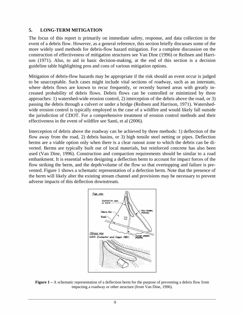
Interception of debris above the roadway can be achieved by three methods: 1) deflection of the flow away from the road, 2) debris basins, or 3) high tensile steel netting or pipes. Deflection berms are a viable option only when there is a clear runout zone to which the debris can be di-verted. Berms are typically built out of local materials, but reinforced concrete has also been used (Van Dine, 1996). Construction and compaction requirements should be similar to a road embankment. It is essential when designing a deflection berm to account for impact forces of the flow striking the berm, and the depth/volume of the flow so that overtopping and failure is pre-vented. Figure 1 shows a schematic representation of a defection berm. Note that the presence of the berm will likely alter the existing stream channel and provisions may be necessary to prevent adverse impacts of this deflection downstream.
Figure 1 – A schematic representation of a deflection berm for the purpose of preventing a debris flow from impacting a roadway or other structure (from Van Dine, 1996).

10
Debris basins are essentially large detention areas that are located on the upstream side of the road. They are designed to retain the coarse material that may be produced by a single debris-flow event (USACE, 2004). A drainage culvert with a straining structure is constructed at the low-point of the basin to pass water and fine material. Sediment that is captured in the basin after a debris flow must be removed to restore the storage capacity for subsequent events (USACE, 2004). Figure 2 shows a schematic drawing of a debris basin.
Figure 2 – Schematic of a debris basin. While this image shows a straining structure and bridge, may basins employ a culvert with a trash rack to pass fines and normal stream flow beyond the roadway (from Van Dine, 1996).
High tensile-strength ring nets or wire rope netting such as are commonly used for rock-fall miti-gation have been successfully used to stop debris flows (see Figure 3) (Thommen and Duffy, 1997; Duffy and DeNatalie, 1996). Debris racks consisting of steel pipes driven in the ground and welded together have also been employed successfully at Lemon Dam near Durango, Colo-rado as seen in Figure 4 (Santi, et al, 2006). Use of these types of barriers is attractive to agencies such as DOTs who often have a limited right-of-way beyond the road because they re-quire a relatively small amount of space. Additionally, since the barrier ideally retains the coarse material but allows water and fines to pass through them, resizing of existing culverts under the roadway may not be necessary.

11
Figure 3 – The use of a high tensile-strength ring net to contain a debris flow (from www.wsl.ch)
Figure 4 – A debris rack above Lemon Dam (near Durango, CO) successfully contained coarse material from a debris flow after the Missionary Ridge Fire of 2002 (from Florida Water Conservation District, 2003).
Finally, debris flows and floods may be passed directly under the road by the use of oversized culverts or bridges. The primary drawback to this approach is the difficulty in predicting the flow rate or volume that will occur in the event of a debris flow (Reihsen and Harrison, 1971). In the case of a bridge crossing, it is vital to place piles or abutments well above the anticipated level of flow because of the high scour potential of debris flows. Culverts must be maintained regularly and cleaned of material after an event to maximize their ability to pass large volumes of debris.

12
6. RECOMMENDATIONS
The decision to remediate debris flow hazards and the selection of mitigation methods is a com-plex process dependent on the space available, anticipated flow volume, acceptable risk levels, and geometry of the drainage channel and roadway. Figure 5 is a flow chart to assist in assessing remediation options.
The variation in cost of each option will likely be governed by the following:
Culvert or bridge (a bridge is spacious but is typically within the ROW)Ring net/wire rope fenceDebris rackDeflection bermDebris Basin
Has the basin recently burned?yes:
no:
5) Choose a mitigation option from the remaining choices based on cost effectiveness
If the basin of interest has been recently burned or logged, then consider basin-wide preventative treatment in addition to engineering mitigation options (see Santi et al, 2006).
1) Assess the need for basin-wide treatment
The space available for a mitigation structure is determined by the ROW and the surrounding topography. Relative space requirements are typically as follows:low:
high:
2) Assess the available space for a mitigation structure
3) Predict the anticipated volume of potential debris flow
4) Determine which mitigation options are feasible based on available space and predicted volume
The relative capacity of each mitigation measure is given below along with the factors that create constraints on capacity:low capacity:
high capacity:
Ring nets/Debris rack - Volume capacity is limited by height and strength of netting and gradient of the channel behind it. Adequate strength anchor rock must be present.Culvert/bridge - These structures are theoretically unlimited in capacity but if they become clogged the capacity essentially becomes zero.Debris basin - The capacity is governed by the natural terrain and size of the retention berm.Deflection berm - The capacity is only limited by the runout area.
Materials/Equipment RequiredDebris rackRing net/wire rope fenceCulvertDeflection bermDebris BasinBridge
Engineering RequiredDeflection bermCulvertDebris rackDebris basinRing net/wire rope fenceBridge
Environmental ImpactCulvertRing net/wire rope fenceDebris rackBridgeDebris BasinDeflection berm
lower cost/commitment:
higher cost/commitment:
Estimate potential volume from past events or from Santi et al, 2006. Debris flows within 1-3 years of a wildfire may be many times larger than in unburned areas.Estimate potential volume from past events and geologic evidence
Figure 5 – Decision guidelines for choosing a debris-flow mitigation option. This is not a comprehensive list of options, but represents some of the more feasible and commonly used mitigation methods for highways.

13
7. CONCLUSIONS
Debris flows are a common geologic hazard in Colorado with increasing probability of occur-rence during the rainy season and times of rapid snowmelt. Debris flows may damage or bury roadways, which may isolate drivers and homeowners and delay emergency services. Therefore, it is important to remove the debris as soon as possible after an event. However, due to the po-tential for repeat events in a short time span and the instability of fresh debris-flow material worker safety is important and must be understood by the clean-up crew. Safety considerations include observation of the following conditions (detailed on the attached Debris-Flow Safety Sheet):
The surrounding area and work site The consistency of the debris material The weather and changing conditions Changes in the flow rate / water quality of the channel Unusual sounds
Collection of data during removal of debris from roadways will provide a database that may as-sist in future ranking and/or mitigating roadways with frequent debris-flow hazards. The attached Debris-Flow Field Data Sheet provides a method of the collection of relevant informa-tion for the development of that database. In areas where debris flows occur frequently or may cause highly hazardous conditions, mitiga-tion methods may be employed. Routine maintenance will still be necessary for existing conditions or mitigated areas. The three primary means for controlling debris flows are:
Watershed-wide erosion control Interception of the debris above the road (deflection berm, debris basin, or ring-nets) Passing of the debris through a culvert of under a bridge
The development of the debris flow database throughout the state will help to identify hazard-prone areas and assist with ranking specific areas for allocation of funds.

14
8. REFERENCES
Andersen, S., 2006, Personal Communication: Federal Highway Administration.
Burns, B., 2006, Personal Communication: Oregon Department of Geology and Mineral Indus-tries.
Cannon, S.H. and Gartner, J.E., 2005, Wildfire-related debris flow from a hazards perspective: Chapter 15 in: Hungr, O. and Jacob, M. eds., Debris-Flow Hazards and Related Phenom-ena, Springer-Praxis Books in Geophysical Sciences, p. 321-344.
Case, W.F., 2000, Debris-Flow Hazards; Utah Geological Survey, Public Information Series 70; dated September.
Center for Disease Control and Provention (CDC), 2003, Landslide (Mudslide) Safety Fact Sheet Depatment of Heath and Human Services; dated November 17.
Coe, J.A., Godt, J.W., Henceroth, A.J., 2002, Debris Flows along the Interstate 70 Corridor; Floyd Hill to the Arapahoe Basin Ski Area, Central Colorado: A Field Trip Guide Book; USGS Open File Report 02-398.
Dept. of Local Affairs (DOLA), 2003, Colorado State Emergency Operations Plan; Landslide - Debris-flow; Annex III; Office of Emergency Management; Dated: September 1.
Duffy, J.D. and DeNatale, J.D., 1996, Debris Flow Mitigation Using Flexible Barriers, Proceed-ings of the 47th Annual Highway Geology Symposium, 243-252 pp.
Gentry, R., 2006, Personal Communication: Oregon Department of Transportation.
Hungr, O., Morgan, G.C., Vandine, D.F. and D.R Lister. 1987. Debris flow defenses in British Columbia. In Debris Flows/ Avalanches: Process, Recognition, and Mitigation, p. 201-222. Ed. By J.E. Costa and G.F. Wieczorek, Boulder, Geological Society of America, Reviews in Engineering Geology, 7.
Heppler, L., 2006, Personal Communication, Utah Geological Survey.
Highland, L.M., Ellen, S.D., Christian, S.B., and Brown III, W.M., 1997, Debris-Flow Hazards in the United States, U.S. Geological Survey Fact Sheet 176-97
Hofmeister, R. J., 2000, Slope Failures in Oregon: GIS Inventory for Three 1996/97 Storm Events, Oregon Department of Geology and Mineral Industries Special Paper 34, 20 p., 1 compact disc.
LeGrande, D., 2006, Personal Communication: Virginia Department of Transportation.
Miller, S.M., 2003, Development and Implementation of the Idaho Highway Slope Instability and Management System (HiSIMS), NIATT Report #N03-07; Dated: June.
Miller, C.D., 1989, Potential Hazards from Future Volcanic Eruptions in California: USGS Bul-letin 1847, 17p.

15
Moses, L.J., 2006, Personal Communication: Washington Department of Transportation.
National Disaster Education Coalition (NDEC), 1996, Landslide and Debris Flow (Mudslide); NDEC comprised of American Red Cross, FEMA, IAEM, IBHS, NFPA, NWS, USDACSREES, and USGS
Noe, D., 2006, Personal Communication: Colorado Geological Survey
Occupational Safety and Health Administration (OSHA), 1989, Occupational Safety and Health Standards – Excavations, Department of Labor, Title 29 Code of Federal Regulations (CFR) part 1926; dated October 31.
Reihsen, G. and Harrison, L.J., 1971, HEC 9: Debris Control Structures; Hydraulics Branch, FHWA; Dated: March.
Rivers, B.S., 2006, Personal Communication: Federal Highway Administration.
Rogers, W.P., 2003, Map of Critical Landslides of Colorado; in: in Boyer, D.D., Santi, P.M., and Rogers, W.P., eds., Engineering geology in Colorado—Contributions, Trends, and Case Histories: AEG Special Publication 15, Colorado Geological Survey Special Publication 55, on CD-ROM.
Russell, C., In Preparation, Modification to the Colorado Rockfall Hazard Rating System, Mas-ter’s Thesis, Colorado School of Mines.
Santi, P., Higgins, J., Cannon, S., DeGraff, J., deWolfe III, V.J., Soule, N.C., Brock, R., and Gartner, J.E., 2006, Evaluation of Post-Wildfire Debris Flow Mitigation Methods and Development of Decision-Support Tools; USGS Contract 04CRGR0001, JFSP Contract 03-1-4-14; Dated: May 31, available at http://jfsp.nifc.gov/projects/03-1-4-14/03-1-4-14_final_report.pdf.
Thommen, R.A. and Duffy, J.D., 1997, Testing and application of flexible wire rope netting bar-riers to retain mud and debris flow, Geobrugg Technical Bulletin #10.
U.S. Army Corps of Engineers (USACE), 2004, Analyses of the debris and sedimentation im-pacts at selected debris basins associated with the wildfires of 2003 and the December 25, 2003 storm, Hydrology and Hydraulics Section, U.S. Army Corps of Engineers, Los Angeles District, after action report DRAFT, 45p, 25p.
USGS, 2005, Southern California Landslides – An Overview; Fact Sheet 2005-3107, available at http://pubs.usgs.gov/fs/2005/3107/pdf/FS-3107.pdf.
VanDine, D.F. 1996. Debris Flow Control Structures for Forest Engineering: British Columbia Ministry of Forests Research Program, Victoria, B.C., Working Paper 08/1996 (available at www.for.gov.bc.ca/hfd/pubs/Docs/Wp/Wp22.htm accessed on 6/19/2006.), 68p.
Washington State Department of Transportation (WSDOT), 1995, Guidelines for the P-3 Unsta-ble slope inventory and prioritization process (www.wsdot.wa.govbiz/geotech/ guidelines.pdf)

Appendix A
Debris-Flow Safety Sheet
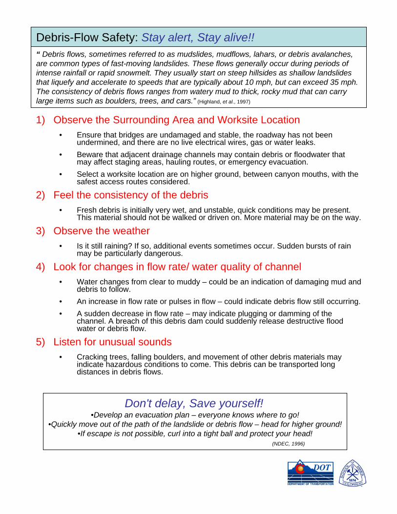
1) Observe the Surrounding Area and Worksite Location• Ensure that bridges are undamaged and stable, the roadway has not been
undermined, and there are no live electrical wires, gas or water leaks. • Beware that adjacent drainage channels may contain debris or floodwater that
may affect staging areas, hauling routes, or emergency evacuation. • Select a worksite location are on higher ground, between canyon mouths, with the
safest access routes considered.
2) Feel the consistency of the debris• Fresh debris is initially very wet, and unstable, quick conditions may be present.
This material should not be walked or driven on. More material may be on the way.
3) Observe the weather• Is it still raining? If so, additional events sometimes occur. Sudden bursts of rain
may be particularly dangerous.
4) Look for changes in flow rate/ water quality of channel• Water changes from clear to muddy – could be an indication of damaging mud and
debris to follow.• An increase in flow rate or pulses in flow – could indicate debris flow still occurring. • A sudden decrease in flow rate – may indicate plugging or damming of the
channel. A breach of this debris dam could suddenly release destructive flood water or debris flow.
5) Listen for unusual sounds• Cracking trees, falling boulders, and movement of other debris materials may
indicate hazardous conditions to come. This debris can be transported long distances in debris flows.
“ Debris flows, sometimes referred to as mudslides, mudflows, lahars, or debris avalanches, are common types of fast-moving landslides. These flows generally occur during periods ofintense rainfall or rapid snowmelt. They usually start on steep hillsides as shallow landslides that liquefy and accelerate to speeds that are typically about 10 mph, but can exceed 35 mph. The consistency of debris flows ranges from watery mud to thick, rocky mud that can carry large items such as boulders, trees, and cars.” (Highland, et al., 1997)
Debris-Flow Safety: Stay alert, Stay alive!!
Don't delay, Save yourself!•Develop an evacuation plan – everyone knows where to go!
•Quickly move out of the path of the landslide or debris flow – head for higher ground!•If escape is not possible, curl into a tight ball and protect your head!
(NDEC, 1996)

Appendix B
Debris-Flow Field Data Sheet

Date of observation:___/___/____ Name of observer:____________________Date of occurrence (if known):___/___/____ CDOT District no:__________Photo file location:_________________________ Highway rte. no.:___________
Estimated sight distance:____________ Posted speed limit (mph):__________
Vehicles involved: yes_____ no_____ If yes, describe damage/injury if known (the best source for getting detailed accident information will be from the State Patrol):_______________________________________________________________________________________________________________________________________
1. Damage to culvert or other structures: yes_____ no_____ If yes, describe (the size and type of culvert can be collected in the office from the “as-built” plans or from the resident engineer):_________________________________________________________________________________________________________
2. Other debris mitigation measures: yes_____ no_____ If yes, what type:___________________________3. Debris flow limits: Beginning Mile Marker: ________ Ending Mile Marker: _________4. Average depth of debris on road: ___________5. Did the debris cross the road and travel down the other side: yes_____ no_____
Was this material removed: yes_____ no_____6. Volume Estimate: Number of trucks _____ Truck capacity:_____ Estimated percent full:______
Other method of estimating volume: _________________________________________7. Description of material removed:
_____ Fine (soil and sand with most rocks smaller than 1 ft. in diameter)_____ Fine and Coarse (soil and sand with numerous rocks larger than 1 ft. in diameter)Average rock diameter: ________Largest rock diameter: ________
8. Other debris present (i.e. logs):____________________________________________________________
Debris-Flow Field Data Sheet :
Provide the following information as completely as possible:1. Landowners within debris-flow source area: __________________________________2. Rain gauge information (if available):
• Station ID: ________• Is the Station within the watershed?
yes no (if no, distance from watershed: _______)• Storm Total (in): ______ • Duration (hrs): ______• Maximum Intensity (in/hr): __________
3. Basin condition (circle all that apply): natural burn logging mining new development other _____________
Include the following information with the file:• Topographic map outlining drainage area• Aerial photos (if available)
For Office Use:

Explanation:
approximate slope (horizontal: vertical)
approximate location of thickness estimate
building or structure North
Approximate Scale:1in = ____ ft
Draw a diagram: Draw a plan view of the canyon producing the flow including the following features; canyon name (if known), road width (label road name or route number), paved shoulder, right-of-way (if known), and culverts and/or debris mitigation structures. Include a north arrow and an approximate scale. Sketch approximate limits of debris flow deposit with thickness estimates and approximate slope. Also include any identifiable structures (house, telephone poles, etc.) or features that will help location the canyon in the future.
Box culvert
Crow Canyon
6’
10:1
6’
10:1
4’
2’3’
#105 Canyon Way
ROW
Example:
SR-54