Embed Size (px)
Citation preview

13th North American Waste to Energy Conference May 23-25, 2005, Orlando, Florida USA
NAWTEC13-3157
Evaluation of Chloride Corrosion Reduction With Chemical Additives at Maine Energy Recovery
Introduction
J. David Martin Fuel Tech, Inc 512 Kingsland Dr Batavia,IL 60510 [email protected]
Over the last several years it has been reported extensively in the literature that chloride induced corrosion of high temperature surfaces in Waste to Energy (WTE) boilers is one of the most costly problems in the industry. This problem can
result in replacement of superheater pendents as often as annually in some units or the costly use of higher alloyed
materials to either shield the metal surfaces or serve as replacement tube material. The cost-effectiveness of the replacement alloys has not been proven in many cases and therefore the industry has been looking for alternative solutions to evaluate. This paper will address the evaluation of
chemical solutions to the problem and also a novel method for measurement of corrosion rates in the high temperature flue gas near WTE superheater pendents.
Background In February, 2005 Maine Energy Recovery Company (MERC)
of Biddeford, ME and Fuel Tech Inc. of Batavia, IL entered into an agreement to evaluate a corrosion measurement tool and select chemical corrosion inhibitors at MERC's Biddeford facility. The Biddeford facility consists of two 300 ton/day WTE units burning refuse derived fuel (RDF) that have experienced a long term problem with chloride induced corrosion that has led to increased replacement costs over the last several years for the superheaters in these units. A more complete history of MERC's problems and previously evaluated solutions can be found in Ken Robbins paper delivered at NA WTEC 2004. In this paper, Ken detailed their attempts to use shielding, alternate metallurgies, and various sootblowing strategies to mitigate the corrosion found in the unit. Ken also detailed their experience with Fuel Tech Inc.'s chemical Slag Control program over the last several years and
their conclusion that this program did help control slag and minimize cleaning outages, but had no discernable effect on the corrosion problems they had experienced.
The corrosion problem at MERC currently can be described as isolated to about 5% of the superheater pendent surfaces which experience corrosion rates ranging from 0.020 to 0.050 inches per month and that this results in tube failures
99
Ken Robbins Maine Recovery Company PO Box 401 Biddeford, Maine 04005 ken. [email protected]
as early as 7 months into a run and the need for replacement of the entire pendent annually. A photo of a recently removed tube with a failure is shown in Figure I. The pattern of metal loss is illustrated in Figure 2 where severe metal loss is shown on opposite sides of the tube. An observation of the plant is that this thinning which is on the sides tangential to flue gas flow occurs on opposing tubes and these tubes show similar metal loss.
FIGURE 1 - Close-up of rough, wasted surface covered with friable corrosion product layers.
FIGURE 2 - Deep, general metal loss along opposite sides
Copyright © 2005 by ASME

Theory of Chloride Induced Corrosion in WTE Plants The TNO report titled "Review on Corrosion in Waste Incinerators and Possible Effect of Bromine" has the most
complete mechanistic explanation for the severe corrosion suffered by WTE units. In addition to the overall analysis of the primary chemical components involved in this corrosion mechanism, it provides the series of equations that explain
why chloride corrosion occurs at the temperature and metallurgical conditions of a waste incinerator. This explanation follows.
The current understanding of the mechanisms of high temperature corrosion in waste combustion plants is reviewed in several papers. In the first pass above the grate in-furnace corrosion by high CO levels and reducing atmospheres is well known. In practice a pragmatic solution is a refractory lining which is applied on the waterwalls in the first pass of most incinerators. In addition to CO reducing conditions in these areas can also result from deposit formation enhanced by the temperature gradient and condensing substances. In fact alkalimetal chlorides have been found in deposits near the metal surface.
It is generally accepted that the high level of chlorides in the waste is the core of the problem. High temperature corrosion in waste incinerators is caused by chlorine either in the form of HCl, Cll, or combined with Na, K, Zn, Pb, Sn and other elements. In particular both gaseous HCI with and without a reducing atmosphere and molten chlorides within the deposit are considered major factors. Sulphur compounds, which under certain circumstances are corrosive compounds itself, can enhance or reduce the corrosion by chlorine. The most important factors in high temperature corrosion are the metal temperature and the temperature difference between gas and metal, the flue gas composition, deposits formation and reducing conditions, and the Sal / HCl ratio.
The following mechanisms can be distinguished.
• Corrosion by HCl/CI2 or SO/SOj containing gas under oxidizing or oxidizing/reducing conditions.
• Corrosion by solid or molten deposits of metal chlorides and sulfates.
These mechanisms are well described by several authors, and one of the pictures explaining the various steps is given in Figure 3.
100
Figure 3- Sequence of chemical reactions explaining corrosion of incinerator boiler tubes (Ref. 60, Krause, 1986, 1993).
Corrosion by chlorine containing gas This mechanism is generally accepted for metal temperatures above about 450°C and is mentioned as 'active oxidation '. Alkali chlorides in particular NaCl, CaCI] and KCl can be present already, or can be formed by the combustion and subsequent reaction of alkali oxides:
Na20 + 2HCl = 2NaCl + H20 {I] Under ideal conditions (good mixing. su
fficient residence
time) alkali chlorides can, provided there is enough S02 and 02, be sulfated according to the reaction:
This would result in formation of sulfates and volatile HC!. At the relatively low tube wall temperatures of most waste incinerators the sulfates are not very harrriful and the HCI formed will be transported to the flue gas clean up system. However if the gas reaches the cooler tube walls before the reaction is completed the alkali metals will tend to condense on the cooler metal. In this case on the metal further sulfate formation can occur under the release of HCI which causes high chlorine partial pressures and enhanced corrosion.
Without S02 at 500 °C NaCl and iron oxides can form Cl2 accordingly:
Calculations of the dissociation constant of HCI as a function of temperature indicate that under oxidizing conditions up to gas temperatures of 600°C chlorine is present as Ci2 , whereas above 600°C in the presence of water vapor formation of HCI is enhanced according to the reaction:
At about 500°C Cl2 can penetrate pores or cracks in an oxide layer. At the low oxygen partial pressures as exist near the
Copyright © 2005 by ASME
metal-oxide scale boundary the metalchlorides are the more stable phase. The reactions (3-4) can result in a Cl2 partial pressure sufficiently high to react directly with the steel to form FeCh
Fe + Cl2 = FeCl2 (solid) [6J
The vapor pressures of metalchlorides will depend primarily on the temperature and the HCI content of the gas. In addition the type of oxide (and alloy) can influence the vapor pressure considerably. The vapor pressure of FeCl2 already at low temperatures is relatively high. As a result formation of FeCl2 can decrease the adherence of the oxide scale or can cause spallation of the oxide layer.
Iron chlorides form, and due to their volatility, migrate out from the corrosion product. At higher oxygen partial pressures near the oxide-gas interface, these chlorides are converted to oxides and liberate chlorine. These new oxides are not formed as a perfect layer and do not offer protection. Part of the liberated chlorine migrates back through the oxide/deposit to react with the metal at the oxide-metal interface, and form metal chlorides again.
FeCl2 (solid) = FeCl2 (gas) [7J
In this process the chlorine has a catalytic effect on the oxidation of the metal resulting in enhanced corrosion. The kinetics of active oxidation is mainly determined by the evaporation and outward diffusion of FeCl2• Similar chlorine corrosion and regeneration cycles may proceed via FeClj and it is possible for the ferrous iron to be oxidized to the ferric state which, when oxidized liberates chlorine as well.
4FeCl2 + 4HCl + O2 = 4FeCl3 + 2H20 [1 OJ
With regard to volatility different compounds can be compared based on the temperature T4 at which the vapor pressure reaches 10-4 bar. For some compounds vapor pressure values are given in Table 1.
Table 1- T4 temperatures of metal chlorides of main alloying elements
Metal chloride
FeCl2 FeClj CrCl2 CrClj NiCl2
536 167 741 611 607
10 1
From all these figures it can be explained that low alloy steels and iron base alloys have a limited resistance against active oxidation. High alloyed materials and in particular nickel base alloys have a much better resistance, which can be explained by the fact that chlorides are more difficult to form and, once formed, their relatively low volatility. Except for the FeClj most T4 temperatures are well above 500°C indicating that this mechanism is most relevant to superheaters and less to evaporators. 1
On-line Measurement of WTE Flue Gas Corrosion Now that the problem and cause are clearly established, the biggest challenge in taking corrective action of any kind is to
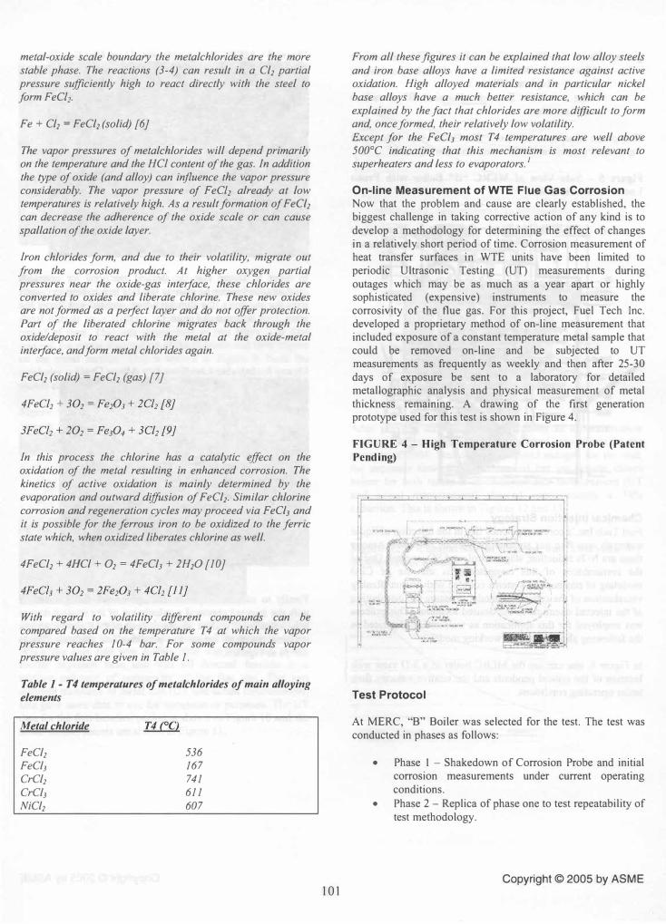
develop a methodology for determining the effect of changes in a relatively short period of time. Corrosion measurement of heat transfer surfaces in WTE units have been limited to periodic Ultrasonic Testing (UT) measurements during outages which may be as much as a year apart or highly sophisticated (expensive) instruments to measure the corrosivity of the flue gas. For this project, Fuel Tech Inc. developed a proprietary method of on-line measurement that included exposure of a constant temperature metal sample that could be removed on-line and be subjected to UT measurements as frequently as weekly and then after 25-30 days of exposure be sent to a laboratory for detailed metallographic analysis and physical measurement of metal thickness remaining. A drawing of the first generation prototype used for this test is shown in Figure 4.
FIGURE 4 - High Temperature Corrosion Probe (Patent
Pending)
r -.--..--- . � ,
..
Test Protocol
At MERC, "B" Boiler was selected for the test. The test was conducted in phases as follows:
• Phase I - Shakedown of Corrosion Probe and initial corrosion measurements under current operating
conditions. • Phase 2 - Replica of phase one to test repeatability of
test methodology.
Copyright © 2005 by ASME
• Phase 3 - First test of ability of "Chemical A" to reduce corrosion rates.
• Phase 4 - Replica of Phase 3. • Phase 5 - First Test of "Chemical B" to reduce
corrosion rates.
The probe was inserted into "B" Boiler just below the superheater pendent at the location shown in Figure 5.
Figure 5 - Side View of MERe "8" 80iler with Probe Location Shown in Red
Chemical Injection Strategy Fuel Tech Inc.'s core competency lies in the injection of liquid materials into flue gas streams for various purposes. Among
these are NOx reduction, slag control, and S03 control. One of the cornerstones of this competency is the use of CFD modeling of combustion systems coupled with Virtual Reality visualization of the completed model to assure the distribution of the injected chemical to the desired locations. This process was employed for this application as well and is illustrated in the following photos from the working model.
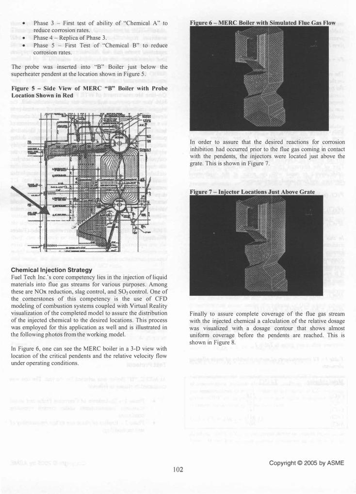
In Figure 6, one can see the MERC boiler in a 3-D view with location of the critical pendents and the relative velocity flow under operating conditions.
102
In order to assure that the desired reactions for corrosion inhibition had occurred prior to the flue gas coming in contact with the pendents, the injectors were located just above the grate. This is shown in Figure 7.
Finally to assure complete coverage of the flue gas stream with the injected chemical a calculation of the relative dosage
was visualized with a dosage contour that shows almost uniform coverage before the pendents are reached. This is shown in Figure 8.
Copyright © 2005 by ASME

Results Phase one and two of the test were an equipment shakedown and an effort to determine the reliability of using a removable metal sample as a realistic measure of corrosion in a short period of time. This was determined in two ways. The first
was just the visual observation of the deposits and their impact on the metal surface. This is shown in Figure 9. Note the
similarity with the surface view of the actual superheater tube shown earlier in Figure I.
Figure 9 - Probe Sample after Exposure to Flue Gas
Stream
The second factor was to evaluate the rate of metal loss of the sample compare to the historical rates of the pendent tubes. While the loss rate was higher, this was attributed to the shorter exposure time and was till deemed feasible as a
relative indicator of corrosivity of the flue gas. The two different measures of metal loss (VT and actual measurement) also gave more data to use for comparative purposes. The VT data for the first baseline period is shown in Figure 10 and the actual measurements are shown in Figure 11.
103
Figure 10 - UT Measurements at Different Times During
Exposure Period
I: ""'", -- o-j : '" ""-! - �---------------""-� �------------....
-
Figure 1 1 - Remaining Wall Thickness at Different
Positions on the Probe Untr .. ted !amp., 1
After proving the viability of the probe as a measurement device, the first application of chemical was begun in the summer of 2004. Due to some planned outages for the unit, the exposure time was more limited but the results shown below for both methods of corrosion rate measurement (UT and actual measurement) showed approximately a 30% reduction. This is shown in Figures 12 and 13.
Figure 12 - Comparison of Treated and Untreated UT Measurement Results
'� �,�--- --,----
"",,,,, � '" ." ..... ,:::---.--
"" ""-
"'" :
� � I
----.
Copyright © 2005 by ASME

Figure 13 - Comparison of Area of Greatest Metal Loss at
800 Deg F (Samples 1 and 2 are Baseline and 3 and 4 are treated)
Conclusion The evaluation of chloride corrosion inhibitors at Maine
Energy Recovery Company is still ongoing and with the favorable results of the testing to date, it is expected that the next round of results will yield corrosion rate reductions beyond the 50% level desired. Phase 5 will begin shortly and
results should be available soon. Much has been learned about the science of corrosion monitoring and the chemistry of corrosion in WTE units and a commercial program for this purpose is expected in the coming months.
Copyright © 2005 by ASME 104