Embed Size (px)
Citation preview

Evaluation of Antenna Designs for a Spillway PIT-Tag Detection
System at Bonneville Dam: Abridged Report
Roger Anderson1
and Sandra L. Downing2
1Destron Fearing Corporation, Digital Angel Corporation
490 Villaume Ave
South St. Paul, Minnesota 55075-2445
2Fish Ecology Division, Northwest Fisheries Science Center
National Marine Fisheries Service
National Oceanic and Atmospheric Administration
2725 Montlake Boulevard East
Seattle, Washington 98112-2097
Technical report prepared for
Division of Fish and Wildlife, Bonneville Power Administration
U.S. Department of Energy
P.O. Box 3621
Portland, Oregon 97208-3621
Project 1983-319-00
Contract 35800
August 2009


1
Unmodified Spillbay
Spillbay vertical rising gate
Spillbay
Dam
Spillbay Crest
Ogee
Introduction
In order to improve survival of salmonids migrating through the federally operated
hydroelectric dams within the Columbia River Basin, the fish managers have changed
how water is managed at these facilities. In the 1990s, large numbers of juvenile
salmonids bypassed the hydroelectric dams by being directed through the collection and
monitoring facilities at the dams. Currently, the practice is to bypass more fish via the
dam spillways. The result is that significantly less data are being collected from the
migrants that are tagged with passive integrated transponder (PIT) tags because the
collection and monitoring facilities have PIT-tag interrogation equipment, but the
spillways do not. Consequently, models used to evaluate the effectiveness of current
management actions and restoration strategies are weakened by having fewer data points
To avoid the loss of these data used
to inform critical management
decisions for ESA-listed salmonid
stocks, we need to develop systems
that will interrogate tagged fish in
spillways.
With the purpose of addressing the
above fish data needs, The Fish
Ecology Division of the Northwest
Fisheries Science Center (National
Marine Fisheries Service, NOAA)
started a project in 2006 to
investigate the development of a
PIT-tag detection system to
interrogate fish passing via
spillways. The highest priority was
the spillway at Bonneville Dam
where each of the 18 spillbays is
equipped with a vertical rising
control gate (Figure 1). The goal
was to develop a PIT-tag system for
Figure 1. Photo of spillway at Bonneville
Dam (top) and diagram showing the
layout for one of its unmodified
spillbays.
an unmodified individual spillbay.
The second priority was to develop a
2
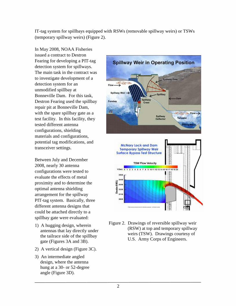
IT-tag system for spillbays equipped with RSWs (removable spillway weirs) or TSWs
(temporary spillway weirs) (Figure 2).
In May 2008, NOAA Fisheries
issued a contract to Destron
Fearing for developing a PIT-tag
detection system for spillways.
The main task in the contract was
to investigate development of a
detection system for an
unmodified spillbay at
Bonneville Dam. For this task,
Destron Fearing used the spillbay
repair pit at Bonneville Dam,
with the spare spillbay gate as a
test facility. In this facility, they
tested different antenna
configurations, shielding
materials and configurations,
potential tag modifications, and
transceiver settings.
Between July and December
2008, nearly 30 antenna
configurations were tested to
evaluate the effects of metal
proximity and to determine the
optimal antenna shielding
arrangement for the spillway
PIT-tag system. Basically, three
different antenna designs that
could be attached directly to a
spillbay gate were evaluated:
1) A hugging design, wherein
antennas that lay directly under
the tailrace side of the spillbay
gate (Figures 3A and 3B).
2) A vertical design (Figure 3C).
Figure 2. Drawings of reversible spillway weir
(RSW) at top and temporary spillway
weirs (TSW). Drawings courtesy of
U.S. Army Corps of Engineers.
3) An intermediate angled
design, where the antenna
hung at a 30- or 52-degree
angle (Figure 3D).

3
L~ 0 in
L ~ 55 in
D ~ 4 ft
D ~ 3 ft
D ~ 2 ft
D ~ 1 ft
Antenna Coil
GateFerrite
Gate open at a
distance
D (ft)
Horizontal
activation distance
L (in)
# of telegrams
broadcasted for a
regular tag
1 55 2.4
2 0 0
3 0 0
4 0 0
Downstream
(Figure 2) Side View of Antenna Configuration
(30 degree)
L~ 0 in
L~ 0 in
Read Area
30 deg.
* )))
* )))
(Figure 4) Side View of Antenna Configuration (90 degree)
L ~ 120 in
L ~ 35 in
L ~ 85 in
L ~ 105 in
D ~ 4 ft
D ~ 3 ft
D ~ 2 ft
D ~ 1 ft
Antenna CoilGate
Gate open at a
distance
D (ft)
Horizontal
activation distance
L (in)
# of telegrams
broadcasted for a
regular tag
1 120 5.3
2 105 4.6
3 85 3.7
4 35 1.5
Downstream
Read Area
90 deg. Ferrite
* )))
* )))
L~ 0 in
L ~ 89 in
L ~ 21 in
L ~ 72 in
D ~ 4 ft
D ~ 3 ft
D ~ 2 ft
D ~ 1 ft
Antenna Coil
Gate
Ferrite
Gate open at a
distance
D (ft)
Horizontal
activation distance
L (in)
# of telegrams
broadcasted for a
regular tag
1 89 3.9
2 72 3.2
3 21 0.9
4 0 0
Downstream
(Figure 5) Side View of Antenna Configuration
(52 degree)
52 deg.
Read Area
* )))
* )))
L~ 0 in
L ~ 88 in
D ~ 4 ft
D ~ 3 ft
D ~ 2 ft
D ~ 1 ft
Antenna CoilGate
Ferrite
Gate open at a
distance
D (ft)
Horizontal
activation distance
L (in)
# of telegrams
broadcasted for a
regular tag
1 88 3.9
2 65 2.9
2 ½ 43 1.9
3 0 0
Downstream
(Figure 1) Side View of Antenna Configuration
(30 degree 5' X 25')
L~ 65 inL~ 43 in
Read Area
30 deg.
* )))
* )))
L~ 0 in
A
B
C
D
Figure 3. Side view of four antenna configurations tested in the repair bay at Bonneville
Dam. Views A and B show hugging design with antennas of different sizes,
view C is a vertical (90-degree) antenna, and view D is a 52-degree,
intermediate angled antenna design.

4
Other parameters tested were antenna size (5 × 25 ft vs. 3 × 25 ft) and ferrite-tile shield
configuration. Configurations tested included different space between tiles, different
distance from the antenna wires, and a ferrite shield covering the entire gate bottom vs. a
shield of strips covering only the metal ribs of the gate bottom.
Although the testing included both 12- and 23-mm tags, to expedite the reporting process,
we include only results with 12-mm tags in this abridged report. In addition, the abridged
report covers only the main results of this work. A proprietary report documenting all of
the tests conducted has been submitted to NOAA Fisheries (Anderson et al. 2009)
The purpose of this report is to provide the fisheries community with a summary of the
testing results, conclusions drawn, and recommendations as to the next steps needed in
developing a PIT-tag detection system for the unmodified spillbays at Bonneville Dam.
Toward this goal, we include a description of an alternative detection system wherein
antennas could be installed into the ogee section of the spillbay rather attaching them to
the spillbay gate (as was done here).
Results from R&D work
Hugging antennas
Destron Fearing tested three main types of hugging antennas. Initially, they tested a
5- by 25-ft antenna, which had performed well in preliminary tests conducted in
Minnesota (Chan et al. 2007). This antenna was used to investigate ferrite-tile shielding
configurations and to compare results for this antenna in an actual spillbay vs. results
from preliminary work in the Minnesota test facility.
Ferrite-tile shielding—To test different ferrite-tile shield configurations, Destron tested
the 5- by 25-ft antenna with no ferrite tiles and compared these results to the different
shield configurations. Configurations tested were strips of ferrite tiles that covered the
ribs of the spillbay gate, a full sheet of ferrite tiles (Figure 4), and a full sheet of tiles with
an additional aluminum shield. These measurements were then repeated with the antenna
away from the gate and then in position next to (under) the gate. From these tests,
Destron concluded that the ferrite-tile shield with strips that covered the ribs of the gate
was as effective as a ferrite-tile shield covering the entire bottom (Table 1).

5
Figure 4. Photos of the two tile shielding arrangements tested. Left: strips of ferrite tiles
that match the ribs under the spillbay gate; right: full sheet of ferrite tiles.
Table 1. Measurements of current (in amps) needed to detect a 12-mm tag 33 inches
below the lower end of hugging antenna with each shield design for an antenna
both next to and away from the spillbay gate.
Current (A) needed to detect
a 12-mm tag 33" below the
lower antenna end
Shielding design with hugging antenna
Away from
spillbay gate
Next to
spillbay gate
No ferrite tiles 7.04 11.00
Strips of ferrite tile 6.56 9.12
Full sheet of ferrite tiles 6.40 8.85
Full sheet of ferrite tiles and aluminum shield 7.56 9.30

6
The 5’ wide antenna
sticks out 2’ at edge
of gate. There is also
an 8’ gap.
Results presented in Table 1 show that the least amount of current was needed for the
antenna to read 12-mm tags using the full wall of ferrite tiles. However, the amount of
current needed for the full wall of tiles was not significantly different from the amount
needed for strips of tiles (Table 1). These results were promising because they suggest
fewer tiles may be needed, and therefore it might be possible to design a circular
(doughnut shaped) antenna housing, which would allow water to drain out through the
middle.
Destron Fearing was reported that the 5 by 25-ft antenna performed as predicted based on
what was learned in Minnesota during initial testing in 2007 (Chan et al. 2007). After the
first round of testing in the repair bay, NOAA Fisheries was concerned that the 5-ft wide
antenna would extended too far beyond the spillbay gate (Figure 5). This extension was
of particular concern on the outer edge of the gate, where we know water will be
cascading down from above as it spills around the spill gate. NOAA Fisheries then
requested that Destron Fearing test two designs of 3- by 25-ft hugging antennas: one that
was two-dimensional and a second that would be contoured to follow the curve of the
spillbay gate.
Figure 5. Photo shows the 5-ft-wide antenna at the edge of the gate. It shows how far
out it extends and the gap.

7
L~ 0 in
L ~ 88 in
D ~ 4 ft
D ~ 3 ft
D ~ 2 ft
D ~ 1 ft
Antenna CoilGate
Ferrite
Gate open at a
distance
D (ft)
Horizontal
activation distance
L (in)
# of telegrams
broadcasted for a
regular tag
1 88 3.9
2 65 2.9
2 ½ 43 1.9
3 0 0
Downstream
(Figure 1) Side View of Antenna Configuration
(30 degree 5' X 25')
L~ 65 inL~ 43 in
Read Area
30 deg.
* )))
* )))
L~ 0 in
L~ 0 in
L ~ 55 in
D ~ 4 ft
D ~ 3 ft
D ~ 2 ft
D ~ 1 ft
Antenna Coil
GateFerrite
Gate open at a
distance
D (ft)
Horizontal
activation distance
L (in)
# of telegrams
broadcasted for a
regular tag
1 55 2.4
2 0 0
3 0 0
4 0 0
Downstream
(Figure 2) Side View of Antenna Configuration
(30 degree)
L~ 0 in
L~ 0 in
Read Area
30 deg.
* )))
* )))
Narrower antenna tests—Destron Fearing agreed to would test a 3- by 25-ft antenna
that was narrow enough to fit under the spillbay gate;
however, they cautioned that the
narrow antenna would be unable
to detect a 12-mm PIT tag with a
5-ft spillbay gate opening.
Read-area patterns were derived
for the area directly under each
antenna and not at the opening of
the gate. This is because that is
where the electromagnetic field is
generated. It is important to
realize that the ogee drops
approximately one foot from the
gate opening to the outer edge of
spillbay gate. Therefore, if the
gate is open 1 ft, then the read
area under the antenna must reach
a depth of approximately 2 ft to
cover the entire water column
where tagged fish might be
passing.
The 3-ft wide hugging antenna
definitely did not detect as well as
the 5-ft wide antenna had
(Figure 6). Results showed that
the 3-ft wide antenna would
produce a tag-reading area that
would be effective only if the gate
were open 1 ft. By comparison,
the 5-ft wide antenna could detct
fish with the gate open 2.5-ft.
These tests were run with the
shield composed of stripes of
ferrite-tiles.
Figure 6. Tag-reading ranges (yellow dotted area)
for the 5-ft wide antenna (top) and 3-ft
wide hugging antennas. Tables below
the diagram show the effective gate
openings of each antenna.

8
Contoured antenna
has a small gap and
fits tightly along
the bottom of the
gate
Next, a contoured antenna was tested. This antenna was difficult to construct because the
spillway gate surface changes in multiple directions over its 25-ft span. The contoured
antenna definitely reduced the gap between the gate and the antenna at the outer edge
(Figures 5 and 7).
Figure 7. Photo of contoured antenna
showing smaller gap at the spillbay
gate edge, as well its tight fit along
the bottom of the spillbay gate.
The contoured antenna induced a larger loading effect because more surface area of the
antenna was in contact with metal in the spillbay gate. Consequently, the read area was
reduced slightly near the center of the gate and significantly toward the outer edge of the
gate. Overall, nearly one ampere more was required for the contoured antenna than for
the hugging antenna to activate a 12-mm tag located 28 inches below the gate end
(Table 2). Thus the contoured design would be effective at detecting fish only if the gate
were open no more than 1 foot.
Table 2. Amps required to detect 12 mm tag from tests comparing the contoured and
two-dimensional 3- by 25-ft antennas.
3 × 25 ft antenna
Trial
number L100KHz Q100KHz
Current (A) needed to detect a
12 mm tag 28" below the lower
antenna end – next to gate
Contoured 19 381 uH 216 11.80
Hugging 20 381 uH 202 11.00

9
Since both 3-ft wide antenna designs performed significantly worse than the 5-ft wide
antenna, the 5-ft wide hugging antenna design is recommended. To address the issue of
water on the overhanging portion of the antenna, Scott Bettin (Project Manager at BPA)
and others suggested that Destron use a sloping cap over the antenna to protect it from
cascading water. The Corps may recommend alternative housing designs if the fisheries
community decides to proceed with this design.
Vertical and intermediate angled antenna designs
During construction of the contoured antenna, the Destron Fearing lead engineer
experimented with performance of a vertical antenna. Using the flat, two-dimensional,
3- by 25-ft antenna, he hung the antenna vertically from the spillbay gate. He then
measured read-area with the antenna it hung vertically and again with the antenna tilted
inward (Figure 8).
Figure 8. Photos of the hanging vertical (left) and 52-degree intermediate angled
antennas.
Because the initial measurements of the vertical configuration looked promising, Destron
Fearing conducted a series of tests to investigate the vertical and 52-degree angled
antenna design. For the first set of these tests, a full ferrite-tile shield was attached along
the bottom of the spillbay gate (Figure 9). The vertical antenna was hung against the
front of the spillbay gate, and tag reading measurements were taken. Measurements were
also taken with the antenna at 30- and 52-degree intermediate angles. The vertical
antenna configuration (90 ) had significantly longer read distances than either the 30- or
52-degree angle configuration (Table 3).

10
(Figure 4) Side View of Antenna Configuration (90 degree)
L ~ 120 in
L ~ 35 in
L ~ 85 in
L ~ 105 in
D ~ 4 ft
D ~ 3 ft
D ~ 2 ft
D ~ 1 ft
Antenna CoilGate
Gate open at a
distance
D (ft)
Horizontal
activation distance
L (in)
# of telegrams
broadcasted for a
regular tag
1 120 5.3
2 105 4.6
3 85 3.7
4 35 1.5
Downstream
Read Area
90 deg. Ferrite
* )))
* )))
L~ 0 in
L ~ 89 in
L ~ 21 in
L ~ 72 in
D ~ 4 ft
D ~ 3 ft
D ~ 2 ft
D ~ 1 ft
Antenna Coil
Gate
Ferrite
Gate open at a
distance
D (ft)
Horizontal
activation distance
L (in)
# of telegrams
broadcasted for a
regular tag
1 89 3.9
2 72 3.2
3 21 0.9
4 0 0
Downstream
(Figure 5) Side View of Antenna Configuration
(52 degree)
52 deg.
Read Area
* )))
* )))
Table 3. Maximum vertical read distances for the different antenna designs. At each
maximum vertical distance, the horizontal read distances were measured.
Antenna design (3- × 25-ft)
Vertical read
distance (ft)
Horizontal read
distance (ft)
Vertical (90 ) 4 2.92
Intermediate angle (52 ) 3 1.75
Intermediate angle (30 ) 2 0.0
Hugging 1 4.6
Destron Fearing then determined the read area for the vertical and 52-degree intermediate
angled antennas. The vertical design produced the largest read area of any antenna
design tested (Figure 9; see Figures 5 and 6 for the hugging design). Testing of the
vertical design antenna showed that this antenna could detect a tagged fish with a spillbay
gate open to ~4 ft (remember that at this location below the antenna, the ogee is 1 ft
lower than the gate opening). This 4-ft gate opening could not be tested empirically
because the gate in the repair bay is fixed with a 3-ft opening. The 52-degree
intermediate angled antenna would be able to detect fish with a gate opening of 2.5-3 ft,
which is better than the 1 ft range of the hugging 3-ft wide antenna and about the same as
the 5-ft wide hugging antenna.
Figure 9. Tag-reading range (dotted area) for the vertical (90-degree) and angled
(52-degree) antenna configurations.

11
(Figure 7) Side View of Recommended Antenna Configuration (90 degree)
L ~ 120 in
L ~ 35 in
L ~ 85 in
L ~ 105 in
D ~ 4 ft
D ~ 3 ft
D ~ 2 ft
D ~ 1 ft
Antenna CoilGate
Gate open at a
distance
D (ft)
Horizontal
activation distance
L (in)
# of telegrams
broadcasted for a
regular tag
1 120 5.3
2 105 4.6
3 85 3.7
4 35 1.5
Downstream
Read Area
90 deg.
Recommended
Ferrite on face
* )))
* )))
Ferrite on
bottom of gate
Destron Fearing also tested whether it would be possible to change the shape of the
ferrite tiles. For example, using the 52-degree intermediate angled antenna, they tested
the difference between activating the 12-mm tag with strips of ferrite tile vs. the full sheet
of tiles (Table 4). They determined that there was difference in tag activation distance of
only 1-ft between the two types of shielding.
For future development, Destron-Fearing proposed testing the effectiveness of a small
ferrite shield attached to the downstream face of the gate using the vertical antenna
design (Figure 10). They also propose testing of a 5- by 25-ft vertical antenna design.
Table 4. Results from test to determine the effect of fully-covered or strips of ferrite-tile
shields on the distance measure for activating the 12-mm tag.
Shield configuration
(52° intermediate angled antenna)
Distance of activation
with 12-mm tag (inches)
Fully covered ferrite tile shield 29
Strips of ferrite tile shield 28
Figure 10. Locations of antenna shield recommended for
face of a spillbay gate (shown with a vertical
antenna). Also shown is the location of the
shield that was tested.
12
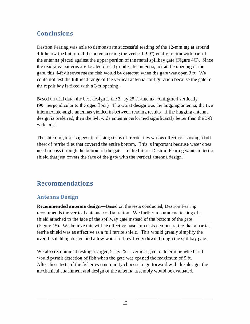
Conclusions
Destron Fearing was able to demonstrate successful reading of the 12-mm tag at around
4 ft below the bottom of the antenna using the vertical (90°) configuration with part of
the antenna placed against the upper portion of the metal spillbay gate (Figure 4C). Since
the read-area patterns are located directly under the antenna, not at the opening of the
gate, this 4-ft distance means fish would be detected when the gate was open 3 ft. We
could not test the full read range of the vertical antenna configuration because the gate in
the repair bay is fixed with a 3-ft opening.
Based on trial data, the best design is the 3- by 25-ft antenna configured vertically
(90 perpendicular to the ogee floor). The worst design was the hugging antenna; the two
intermediate-angle antennas yielded in-between reading results. If the hugging antenna
design is preferred, then the 5-ft wide antenna performed significantly better than the 3-ft
wide one.
The shielding tests suggest that using strips of ferrite tiles was as effective as using a full
sheet of ferrite tiles that covered the entire bottom. This is important because water does
need to pass through the bottom of the gate. In the future, Destron Fearing wants to test a
shield that just covers the face of the gate with the vertical antenna design.
Recommendations
Antenna Design
Recommended antenna design—Based on the tests conducted, Destron Fearing
recommends the vertical antenna configuration. We further recommend testing of a
shield attached to the face of the spillway gate instead of the bottom of the gate
(Figure 15). We believe this will be effective based on tests demonstrating that a partial
ferrite shield was as effective as a full ferrite shield. This would greatly simplify the
overall shielding design and allow water to flow freely down through the spillbay gate.
We also recommend testing a larger, 5- by 25-ft vertical gate to determine whether it
would permit detection of fish when the gate was opened the maximum of 5 ft.
After these tests, if the fisheries community chooses to go forward with this design, the
mechanical attachment and design of the antenna assembly would be evaluated.

13
3' x 25'
Antenna coil Antenna enclosure concept (6" diameter PVC pipe)
Antenna housing—We recommend the use of pipe-style housing for the antenna
housing enclosures (Figure 11). This would permit water to mostly go through the
antenna instead of hitting a solid structure.
Figure 11. Diagram of a pipe style antenna housing.
Alternative antenna location—An alternative option to attaching an antenna to the
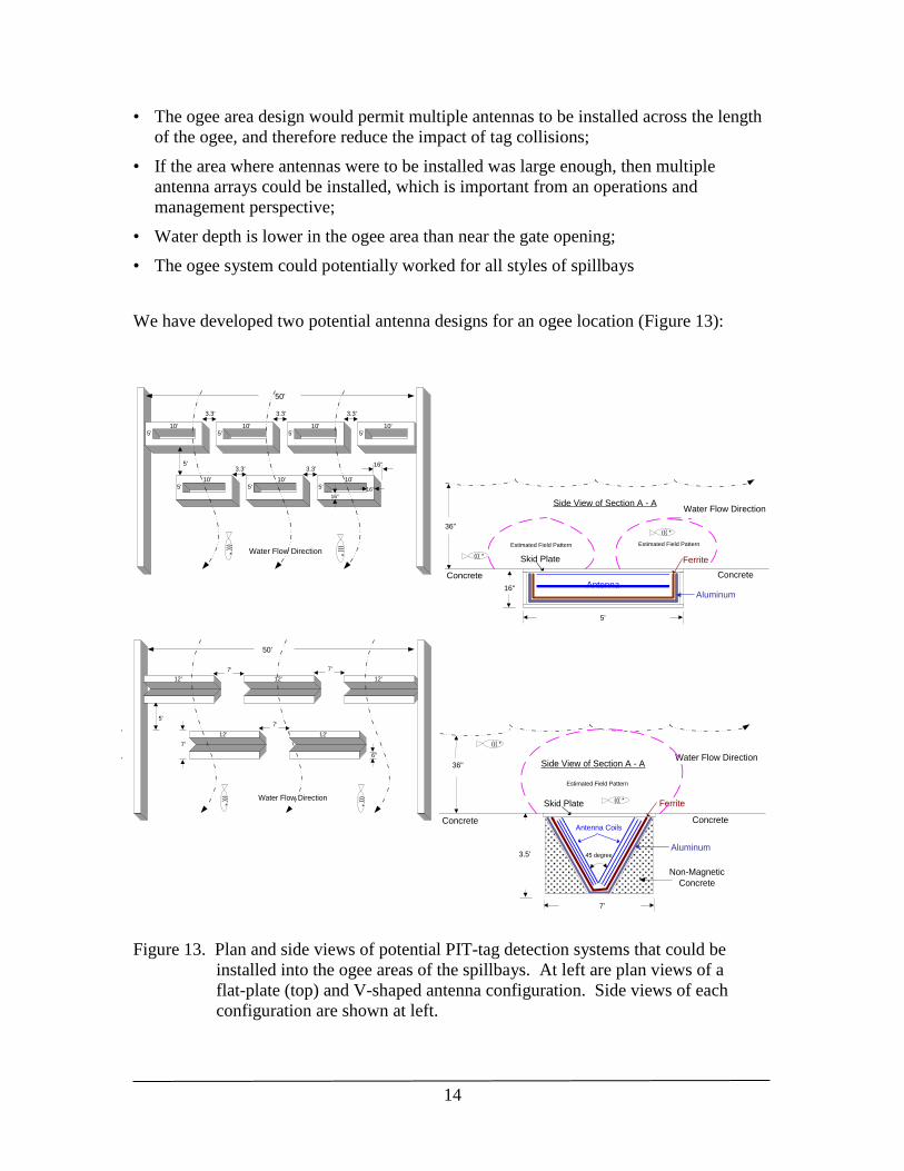
spillbay gate would be to install an antenna system in the ogee area (Figures 1 and 12).
In this location, the water
depth is shallower (1-3
ft, depending on gate
opening), and water
velocity is faster
(65-90 ft/s) than at the
gate location, but the
antennas would be more
protected.
The ogee area is the
location that has been
accepted for the PIT-tag
system scheduled to be
installed for the TSW
spillbay at Ice Harbor
Dam. The ogee location
is attractive for several reasons:
• A system in the ogee area
would not affect hydraulics;
Figure 12. Diagram from USACE showing water
velocities for a TSW system and general
location and water conditions in site where
ogee system would be located. USACE
estimates water velocities of ~65-90 ft/s.
• There are no debris issues in the ogee area;
14
3.3'
10'
Water Flow Direction
Flat Plate Antenna (in the Ogee Area) - Preliminary Proposal
Antenna
Skid Plate
5'
16"
Ferrite
Aluminum
A
A
Side View of Section A - AWater Flow Direction
Top view of Ogee Area
50'
Concrete
((( *
((( *
Concrete
((( *
((( *
10'10'10'5' 5' 5' 5'
3.3' 3.3'
5'
16"
16"
16"
3.3'
10'10'10'5' 5' 5'
3.3'
Figure 8
Estimated Field PatternEstimated Field Pattern
36"
5'
6"
Water Flow Direction
V-Shape Antenna (in the Ogee Area) - Preliminary Proposal
Skid Plate
7'
3.5'
Ferrite
Aluminum
A
A
Side View of Section A - AWater Flow Direction
Top view of Ogee Area
50'
Concrete
45 degree
ConcreteAntenna Coils
Non-Magnetic
Concrete
((( *
((( *
((( *
12' 12'12'
7' 7'
12'12'
7'
7'
Figure 9
Estimated Field Pattern
36"
((( *
3.3'
10'
Water Flow Direction
Flat Plate Antenna (in the Ogee Area) - Preliminary Proposal
Antenna
Skid Plate
5'
16"
Ferrite
Aluminum
A
A
Side View of Section A - AWater Flow Direction
Top view of Ogee Area
50'
Concrete
((( *
((( *
Concrete
((( *
((( *
10'10'10'5' 5' 5' 5'
3.3' 3.3'
5'
16"
16"
16"
3.3'
10'10'10'5' 5' 5'
3.3'
Figure 8
Estimated Field PatternEstimated Field Pattern
36"
5'
6"
Water Flow Direction
V-Shape Antenna (in the Ogee Area) - Preliminary Proposal
Skid Plate
7'
3.5'
Ferrite
Aluminum
A
A
Side View of Section A - AWater Flow Direction
Top view of Ogee Area
50'
Concrete
45 degree
ConcreteAntenna Coils
Non-Magnetic
Concrete
((( *
((( *
((( *
12' 12'12'
7' 7'
12'12'
7'
7'
Figure 9
Estimated Field Pattern
36"
((( *
• The ogee area design would permit multiple antennas to be installed across the length
of the ogee, and therefore reduce the impact of tag collisions;
• If the area where antennas were to be installed was large enough, then multiple
antenna arrays could be installed, which is important from an operations and
management perspective;
• Water depth is lower in the ogee area than near the gate opening;
• The ogee system could potentially worked for all styles of spillbays
We have developed two potential antenna designs for an ogee location (Figure 13):
Figure 13. Plan and side views of potential PIT-tag detection systems that could be
installed into the ogee areas of the spillbays. At left are plan views of a
flat-plate (top) and V-shaped antenna configuration. Side views of each
configuration are shown at left.

15
The flat-plate antenna system would require seven antennas while the V-shaped antenna
system would require five antennas. The V-shaped antennas should be able to detect the
12.5-mm PIT tags in the full 36-inch water depth, while the flat-plate antennas would
probably only detect all tags when water depth was 20 inches deep. Starting in August
2009, Destron Fearing will test antennas with these and additional shapes. One concern
with any of the spillbay antenna designs is the impact of tag collisions. If an ogee-based
PIT-tag system can be designed using smaller (and more) antennas (Figure 13), the
impact of tag collisions could be reduced.
Tag modifications
Another way to improve the efficiency of a PIT-tag detection system for the spillway
would be to shorten the tag telegram time by 50% to make the detection system more
effective (Table 5). For a standard tag telegram (ISO FDX-B protocol), the total time
required to broadcast one complete tag telegram is 30.5 ms; thus the total number of
telegrams that can be broadcast per second is 32.8.
The advantage of a shorter tag-telegram time is that, as the read area narrows with
distance from the antenna, faster reading time will enlarge the effective read area.
Typically to be effective, we need a minimum of 1.0 telegram, but prefer an area that will
cover 1.5 telegrams.
We also recommend that the faster tag be designed to utilize less activation current,
which would provide longer read range.
Table 5. The table demonstrates how a tag with faster telegram timing would double the
number of telegrams that could potentially be detected, which would enlarge the
effective read area produced by an antenna. The example given is for the 3-ft
wide vertical antenna.
Vertical 3 × 25 ft antenna
Gate opening Horizontal activation Telegrams broadcast (n)
distance (ft) distance (in) Regular tag Fast tag
1 120 5.3 10.6
2 105 4.6 9.3
3 85 3.7 7.5
4 35 1.5 3.1

16
Transceiver modifications
Testing was done with the existing BCC transceiver. We recommend modifying this
transceiver system with a receiver circuitry that has higher sensitivity and that can read
the new faster tag. New and existing less expensive transceivers, such as the ACN and
DF2020, may be utilized to drive spillway and ogee type antennas.
Next steps for this project
1. Meet with FFDRWG to discuss pros and cons of the different antenna designs and
location.
2. Meet with Corps to discuss pros and cons in terms of attaching antenna housings.
3. Demonstrate the performance of one or all of the designs using a series of tests
defined by NOAA.
References
Roger Anderson, Alex Artyukhov, Vincent Chan, Roger Clark, Keith Kuhnly, Marc
LeMay, Zeke Mejia, Yuri Smirnov. 2009. Progress Report on Phase II of
Developing a Spillway PIT-tag detection system. Confidential report submitted
to NOAA Fisheries.
Vincent Chan, Alex Artyukhov, Yuri Smirnov, Roger Anderson, Roger Clark, Keith
Kuhnly and Zeke Mejia. 2007. Spillway PIT-Tag Detection System Condensed
Final Report. Confidential report submitted to NOAA Fisheries.