Embed Size (px)
Citation preview

204
EVALUATION AND CONTROL OF THE IN-PLANE STIFFNESS OF TIMBER FLOORS
FOR THE PERFORMANCE-BASED RETROFIT OF URM BUILDINGS
Anna Brignola1, Stefano Pampanin2 and Stefano Podestà3
SUMMARY
The seismic response of existing un-reinforced masonry (URM) buildings is strongly dependent on the characteristics of wooden floors and, in particular, on their in-plane stiffness and on the quality of connection between the floors and the URM elements. It is generally well-recognized that an adequate in- plane-stiffness and proper connections can significantly improve the three-dimensional response of these buildings, obtaining a better distribution and transfer of forces to the lateral load resisting walls. However, the extensive damage observed during past earthquakes on URM buildings of different types have highlighted serious shortcomings in typical retrofit interventions adopted in the past and based on stiffening the diaphragm. Recent numerical investigations have also confirmed that increasing the stiffness of the diaphragm is not necessarily going to lead to an improved response, but could actually result to detrimental effects. The evaluation of the in-plane stiffness of timber floors in their as-built and retrofitted configuration is still an open question and a delicate issue, with design guidelines and previous research results providing incomplete and sometimes controversial suggestions to practicing engineers involved in the assessment and/or retrofit of these type of structures. In this contribution, the role of the in-plane stiffness of timber floors in the seismic response of URM buildings is critically discussed, based on the relatively limited available experimental and numerical evidences. A framework for a performance-based assessment and retrofit strategy of URM buildings, capable of accounting for the effects of a flexible diaphragm on the response prior to and after the retrofit intervention, is then proposed. By controlling the in-plane stiffness of the diaphragm, adopting a specific strengthening (or weakening) intervention, the displacements, accelerations and internal force demands can be maintained within targeted levels. This will protect undesired local mechanisms and aim for a more appropriate hierarchy of strength within the whole system.
1 PhD Candidate, Department of Civil, Environmental and Architectural Engineering, University of Genoa, Italy. 2 Associate Professor, Department of Civil and Natural Resources Engineering, University of Canterbury, Christchurch (Member). 3 Assistant Professor, Department of Civil, Environmental and Architectural Engineering, University of Genoa, Italy.
BULLETIN OF THE NEW ZEALAND SOCIETY FOR EARTHQUAKE ENGINEERING, Vol. 42, No. 3, September 2009
INTRODUCTION
The experience of past earthquakes has shown that the seismic response of existing masonry buildings is strongly dependent on the characteristics of the floors and in particular on their in-plane stiffness and connection quality with the masonry elements. The horizontal diaphragms play a key role in the transmission of seismic actions and the quality of the connections allows the structure to activate its 3-dimensional resources. With the aim of achieving a three-dimensional behaviour of a masonry building and to increase the gravity load capacity of the floors, in the past, quite invasive retrofit interventions on diaphragms and wall-to-diaphragm connections were typically implemented. Frequently, old timber floors have been replaced with more rigid diaphragms, usually comprised of a mixed brick and reinforced concrete structure, connected to the walls by means of concrete beams or concrete dovetail elements, inserted into the masonry thickness. In addition to issues associated to the invasiveness of the solutions adopted and the poor attention paid to the historical and cultural preservation of ancient/heritage buildings, such interventions have in few cases also led to dramatic consequences during past earthquakes. Figure 1
shows typical out-of-plane collapse mechanisms observed in different seismic events, due to excessively stiff diaphragms with inadequate connection to the walls. A particularly undesirable mechanism, common of overly stiffened floors, is the expulsion of the building corners (Lemme et al. 2008) (Fig. 1b, 1f, 1h).
International guidelines on seismic rehabilitation of buildings (FEMA 356 2000; ASCE/SEI 41-06 2007; NZSEE guidelines 2006; OPCM 3274 2005) and international literature (Tena-Colunga & Abrams 1992, 1995, 1996) underline the importance of correctly including the diaphragm flexibility and accounting for the out-of-plane loading of the walls when modelling the response of URM buildings. However, how to account for these effects in a simple manner is not specified, nor clear. Similarly, the importance of the connections between the vertical walls and the diaphragm is recognized to play an important role in the overall response of masonry buildings, and yet, adequate information on how to evaluate such effects is missing.

205
a) b)
c) d)
e) f)
g)h)
Figure 1: Damages on masonry buildings associated to the presence of inadequately stiff floors observed in different
earthquakes in the past: a) 1997 Umbria-Marche earthquake (Italy); b) 2002 Molise earthquake (Italy);c) & d) 2009 Abruzzo earthquake (Italy); e )& f) 2005 Pakistan earthquake (Bothara et al. 2008); h) 1999 Marmara earthquake (Turkey) (Bruneau 2002); g) 2001 Nisqually, WA earthquake (US)(httpearthquake.usgs.gov.).

206
The diaphragm action depends on the type of floor. Therefore, focusing the attention on timber floors, it is of interest to properly evaluate the in-plane-stiffness of existing (as-built) and retrofitted configurations. Some standards (e.g. FEMA 356 2000,) provide reference stiffness values for different types of timber floors, others (e.g. NZSEE Assessment guidelines 2006) propose a simplified analytical procedure to determine the in-plane stiffness starting from the geometrical and mechanical characteristics of the floor.
It is worth noting, however, that very few experimental results are available to support such empirical values or evaluation procedures (ABK 1981, Corradi et al. 2006; Piazza et al. 2008; Peralta et al. 2003, 2004). Furthermore, when looking at the available experimental results, different test set-ups have been adopted with significant discrepancies in the boundary conditions, aspect ratio, type of floors and measured parameters. An additional controversy is evident when discussing which in-plane “stiffness” to adopt from the experimental test results. Given the high non-linearity of the response at earlier stages, due to the behaviour of nailed connections, major differences can occur depending whether an a) initial stiffness, b) secant stiffness or c) tangent stiffness is considered. Benchmark values and testing protocol for such evaluation are not yet available.
The effects of timber diaphragms and the crucial need to evaluate and control the stiffness (within acceptable ranges) are further emphasised when developing an adequate retrofit strategy. Some international guidelines on the rehabilitation of URM buildings (OPCM 3274 2005) suggest few options for the strengthening of the horizontal diaphragms.
In this contribution, a retrofit strategy aimed at improving the global behaviour of the building and changing the hierarchy of strength of local mechanisms by modifying the in-plane stiffness of the diaphragms is proposed. According to a performance-based retrofit approach, the efficiency of alternative retrofit techniques (i.e. concrete topping, FRP, cross board, steel plates) in controlling the stiffness of the diaphragm, and thus obtaining the desired global mechanism, can be assessed. After providing a summary of the state-of-the-art on the role of the in-plane stiffness of timber floors in the seismic response of the masonry buildings, considerations on local and global mechanisms and their hierarchy of strength, as affected by the diaphragm stiffness, are given. An overview on alternative retrofit techniques for existing timber floors is also presented along with a critical discussion on the theoretical and experimental evaluations of the diaphragm stiffness.
AS-BUILT TIMBER FLOORS AND STRENGHTENING TECHNIQUES
Timber floors typically adopted in URM buildings are very simple structures consisting of joists and cross boards nailed to the main elements. Either one-way or, when larger span are required, two-way (cross bonded) floors are used (Fig. 2).
Figure 2: Traditional layout of timber floors a) one-
way and b) two-way (cross bonded).
Strengthening of the floor unit
Alternative seismic retrofit techniques for timber floor diaphragms are available and suggested as viable solution in recent guidelines for seismic assessment and retrofit (OPCM 3274, 2005):
• Cross laminated plywood sheets: consisting of the superposition of a new layer of wood planks or plywood panels over the existing sheathing. Usually the planks and the panels are arranged perpendicular to the existing planks or panels and fixed with screws or nails (Fig. 3a).
• Fibre reinforced Polymers (FRP) or steel plates: consisting of the application of diagonal bracing to the existing wood planks. Either wide sheets of composite materials (FRP), glued to wood by means of epoxy-based resin (Fig. 3b), or light steel plates, nailed to the planks, can be used.
• Concrete topping for composite action: a very common and traditional retrofit method, consisting of a lightweight concrete topping (40-50 mm thick) with or without steel connectors. The slab reinforcement is usually composed of welded wire-mesh (5-6 mm diameter) (Fig. 3c). The connection between the wood rafters and the concrete slab can be obtained through different types of connectors (e.g., nails, L-shaped elements made of steel bars, axial connectors).
Strengthening of the floor-to wall connection
Existing timber floors are usually connected to the lateral walls by simple interlocking between timber beams and masonry or by means of steel ties to improve the local link between masonry and beams (Figs. 4a, b).
In the past, in order to obtain an improved degree of connection between timber floors and masonry unit, concrete curbs were often inserted within the depth of the masonry walls. The extensive damage observed during past earthquakes have, however, highlighted that the inappropriate usage of this standard technique can lead to dramatic consequences due to the excessive weakening of the existing masonry walls. Reversible and non-invasive techniques are generally preferred and suggested by guidelines (Fig. 4). A solution systematically adopted for example U.S. and New Zealand buildings, consists of the direct connection of the wood joists with the lateral walls through the use of steel rods embedded inside the masonry and usually connected with a wall anchor on the external side of the building. This solution is instead not often adopted in ancient masonry buildings in Europe: the frequent use of rough sawn timber for the joists and the high irregularity of the masonry walls can in fact, easily jeopardize the effectiveness of such a solution. Alternative solutions to the direct connection between joists and walls consist of the adoption of connecting elements on the top of the floor for example through the use of steel plates (Fig. 4d) with adequate shapes (i.e V-shape) screwed on the existing floor and welded with stud connectors embedded inside the masonry. Another efficient connection between the wood diaphragm and the masonry walls can be obtained by using the system shown in Figure 4e (Doglioni, 2000). In this connection L-shaped steel elements are connected to the floor by means of screws; both ends of the profile are connected to the lateral masonry unit through threaded steel bars (20-30 mm diameter) and chemically or mechanically connected to the masonry walls.

207
a)
New layer of planks
b)
New layer of planks
FRP
c)
Concrete
Stud connectors
Wire mesh
Figure 3: Typical retrofit techniques for existing timber floors: a) new layer of wood planks; b) diagonal bracing of
composite materials (FRP); c) additional concrete topping.
a) b)
c) d)
Figure 4: Typical retrofit techniques adopted to improve the connection between timber floor and masonry walls: a) & b)
steel ties; c) steel ties perpendicular to beams way; d) L-shape perimeter steel element (Doglioni, 2000).
208
SEISMIC RESPONSE OF MASONRY BUILDINGS WITH FLEXIBLE TIMBER DIAPHRAGM
According to international guidelines on the seismic rehabilitation of buildings (e.g. NZSEE guidelines 2006, OPCM 3274 2005), both the global and local behaviour of URM buildings have to be assessed, accounting for partial/local collapse mechanisms, either in plane or out-of-plane. As mentioned, the damage observation from past earthquakes has confirmed the key role of diaphragm flexibility in affecting the collapse mechanism and, in general, the overall response.
An excessively flexible diaphragm and inadequate tie-in connection between walls and floor can lead to excessive displacement at the floor level, possibly causing overturning of the perimeter out-plane-walls (typically referred to as first-mode of failure and considered the least desirable, Fig. 5). Stiffening the diaphragm by substituting or retrofitting the existing timber floors can limit such out-of-plane behaviour, while increasing the distribution of shear forces to the lateral resisting walls (in-plane). Poor quality masonry or the presence of significant opening can lead to shear, sliding-shear or rocking mechanisms (typically referred to as second modes).
Figure 5: First-mode collapse mechanisms:
out-of-plane wall overturning (De Benedictis et al., 1993).
Furthermore, as mentioned, damages and failures observed in past earthquakes have shown that stiff diaphragms poorly connected to the walls, can still generate undesirable collapse mechanisms. A particular undesirable mechanism, common of overly stiff floors, is the expulsion of the building corners (Lemme et al. 2008) (Fig. 6b, 6c). This local collapse mechanism is not only very dangerous but also quite difficult to predict. The angular deformation that occurs in a masonry cell, due to the different behaviour of the shear resistant walls, leads to shear stress distribution in the diaphragm; consequently the two diagonals of the diaphragm result alternately either in compression or in tension. In correspondence to the compressed corners a concentration of outwards forces occurs, which can activate the mechanism of expulsion of the building corners (Fig. 6a).
International literature confirms the critical role of flexible diaphragms in the overall seismic response of the masonry buildings. Tena-Colunga & Abrams (1992, 1995, 1996) developed analytical dynamic models to study the behaviour of some masonry buildings which were subjected to the 1989 Loma Prieta Earthquake. They showed that a rigid diaphragm assumption is not necessarily conservative for the assessment of many existing buildings, since it underestimates the acceleration of diaphragm and shear walls as well the as out-of-plane displacement of walls. Thus, for the purpose of this paper, a retrofit solution targeting an increase in stiffness would, as a general benefit, lead to a reduction of out-of-plane displacements and possibly accelerations.
a) b)
c)
S
S
Figure 6: Angular deformation of the masonry unit
and expulsion of the building corners.
On the other hand, as the diaphragm flexibility increases, torsional effects were demonstrated to be reduced. This would suggest that when torsion is a concern, due to the layout of the building, a no-intervention or even a reduction in diaphragm stiffness could be preferred.
Few shaking table tests have been carried out on full-scale or half-scale masonry buildings (e.g., Cohen et al. 2002; Bothara, 2004; Paquette & Bruneau 2006). In contrast to what is usually assumed in design, URM buildings with flexible floor diaphragms do not behave as SDOF systems (associated with the in-plane response of the shear walls). Rather, they tend to behave as at least a 2DOF system, with the second degree of freedom associated with the in-plane response of the timber diaphragm.
In order to evaluate the effectiveness of a strengthening technique for timber floors based on an increase of the diaphragm stiffness, numerical studies on the seismic response of historical URM building with timber diaphragms have been carried out by Gattesco et al. (2007, Fig. 7). The numerical analysis of floors loaded in-plane showed a significant increase in the in-plane stiffness when strengthened with steel plates connected to the timber beams through steel dowels. These plates were placed both parallel to the beams and diagonally above the existing boards. The resultant floor in-plane stiffness, was up to 50 times larger than that associated to the as-built configuration. As anticipated, a predefined change to the failure mechanism can be controlled by modifying the in-plane stiffness of the diaphragm by a retrofit intervention. In the as-built configuration, the overturning of the out-of-plane walls was observed due to the excessive in-plane displacement of the floor (Fig. 7a). By increasing the stiffness of the diaphragms, according to the proposed technique (which included a typical tie-back action with the out-of plane walls), the overturning mechanism can be protected by engaging the parallel walls (Fig. 7b). Failure of the shear walls would eventually occur (Fig. 7d), however, a substantial increase in the overall lateral load capacity (50% increases in the base shear) was observed.

209
a) b)
c)
d)
Figure 7: Numerical response of a URM building: deformed shape for (a) flexible diaphragm or (b) rigid diaphragm; maximum deformation and tensile stresses distribution for (c) flexible diaphragm and (d) rigid diaphragm (Gattesco et al. 2007).
Parametrical analyses on a 2:3 scale URM building
In order to gain a better understanding of the effects of flexible diaphragms on the behaviour of masonry buildings under seismic actions, extensive numerical investigations are under way on a series of prototype buildings. As an example, the results of pushover analyses on a simple two storey URM building (Fig. 8a) are shown. The building, 2:3 scale, is characterized by a relatively weak tuff masonry and represents a test-building for shake-table tests at the Enea Laboratory, Rome, Italy (TREMA Project, Technologies for the Reduction of seismic Effects on Architectural Manufactures 2006). The analyses have been carried out using the program Tremuri, specifically developed at the University of Genoa (Galasco et al., 2001) for the daily use of practitioner engineers. The walls, with or without openings, are modelled as equivalent frame systems (Fig. 8c) and the out-of-plane modes are not taken into account. The masonry elements, piers and spandrels, are modelled by non linear beam elements (6 DOFs) characterized by a bilinear behaviour. The floor systems are modelled by elastic elements with a user-defined in-plane stiffness (Exeq, Eyeq, Geq). As described in the following paragraph, the latter should account for both the diaphragm-only stiffness as well as the connector contribution. Four different in-plane stiffness values were considered in order to represent: 1) the as-built floor configuration (Geq = 7.5 MPa); 2&3) stiffer floors as a result of two retrofit interventions on the diaphragm (Geq = 15 MPa; Geq = 75 MPa); 4) an infinitely rigid diaphragm often used in analysis (Geq = 750 MPa).
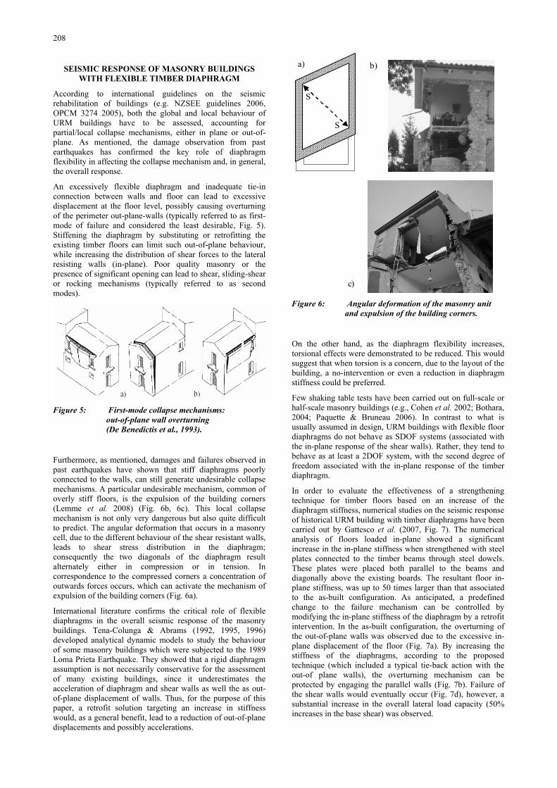
In Figure 9 the results of the push-over analyses (in x-direction) are shown. For each diaphragm stiffness, the capacity curves representative of the equivalent SDOF oscillator are plotted within an ADRS format (i.e. acceleration-displacement response spectra diagram) and compared with the NZS1170: 2004 Design Spectra. An hazard Factor Z= 0.13 has been considered, together with a Return Periods equal to 500 yrs (R= 1.0) and 2500 yrs (R= 1.8) for different soil classes.
Intentionally particular attention was given to the response under the design level earthquake (500 years return period) in a relatively low seismic region (Z= 0.13, typical of Auckland region), which would correspond approximately to 2/3 and 1/3
of the seismic demand in Wellington and Christchurch. It is worth in fact noting that, according to the new Building Act (2004) requirements and the suggestions from the NZSEE Assessment Guidelines (2006), an Earthquake-Prone Building (EPB) would be defined as such if its capacity is likely to be exceeded in a “moderate earthquake”, corresponding to 1/3 the intensity of the design level earthquake. Furthermore, although no action is required if a building pass the one-third criterion (unless a change of use is planned) the NZSEE guidelines “strongly recommend that every effort be made to achieve improvement to at least” 2/3 of the New Building Standard).
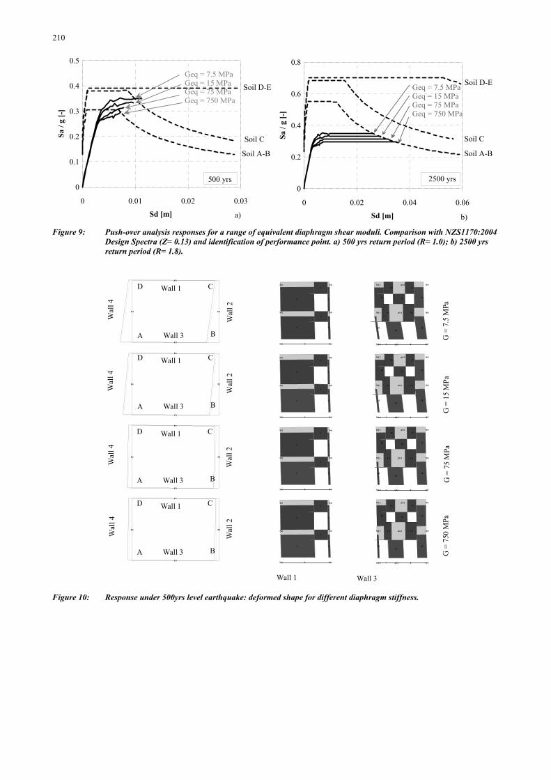
A comparison of the building performance, depending on the stiffness of the floor, was carried out. Figure 10 represents a snap-shot of the deformed shape (plan view, wall 1 and wall 3 elevation views) corresponding to the performance point, while Figure 11a and Figure 11b show the inter-storey drift values for each wall as well as the floors torsional rotation for each level. It can be noted that, when increasing the diaphragm stiffness as a result of the retrofit intervention, the inter-storey drift demand on the weakest wall decreases significantly. In fact, while in the as-built configuration wall 3 is subjected to a high inter-storey drift at the first level, as the stiffness of the diaphragm increased, the response become more regular, with wall 3 and 1 reaching approximately the same inter-storey drift under rigid diaphragm assumptions. As a result, the torsional rotation of the floors is reduced as the diaphragm increases.
A
4.5
0 m
2.50 m3.00 m
E1
E2
E3 E4
E5 E6
N1
N2
N3
N4
N5
N6
E7
E8
E9
E1 0 E11
E1 2 E13
N4
N5
N6
N7
N8
N9
E14 E15
E16 E17
E18E19
E20
E21 E22 E23
n13
n14
n15
N7
N8
N9
N10
N11
N12
E24
E25
n16
n17
n18
N1
N2
N3
N10
N11
N12
Wall 1Wall 2
Wall 3 Wall 4
Wall 1
Wal
l 2
Wall 3
Wal
l 4
x
y
B
CD
Figure 8: Equivalent frame model for a two-storey, 2:3
scaled test UMR building (TREMA 2006). a) Three-dimensional view; b) Plan; c) Equivalent frame model for the different walls.
210
0 0.01 0.02 0.03
Sd [m]
0
0.1
0.2
0.3
0.4
0.5Sa
/ g
[-]
Soil D-E
Soil C
Soil A-B
Geq = 7.5 MPaGeq = 15 MPaGeq = 75 MPaGeq = 750 MPa
500 yrs
0 0.02 0.04 0.06
Sd [m]
0
0.2
0.4
0.6
0.8
Sa /
g [-
]
Soil D-E
Soil C
Soil A-B
Geq = 7.5 MPaGeq = 15 MPaGeq = 75 MPaGeq = 750 MPa
2500 yrs
a) b) Figure 9: Push-over analysis responses for a range of equivalent diaphragm shear moduli. Comparison with NZS1170:2004
Design Spectra (Z= 0.13) and identification of performance point. a) 500 yrs return period (R= 1.0); b) 2500 yrs return period (R= 1.8).
P1
P2
P3
P4
1
2
3 4
5 6
5N 1
N 2
N 3
N 4
N 5
N 6
1 4 1 5
16 17
1 81 9
2 0
2 1 22 2 3
7 8n 13
n1 4
n1 5
N 7
N 8
N 9
N 1 0
N 1 1
N 1 2
P1
P2
P3
P4
1
2
3 4
5 6
5N 1
N 2
N 3
N 4
N 5
N 6
1 4 1 5
16 17
1 81 9
2 0
2 1 22 2 3
7 8n 13
n1 4
n1 5
N 7
N 8
N 9
N 1 0
N 1 1
N 1 2
P1
P2
P3
P4
1
2
3 4
5 6
5N 1
N 2
N 3
N 4
N 5
N 6
1 4 1 5
16 17
1 81 9
2 0
2 1 22 2 3
7 8n 13
n1 4
n1 5
N 7
N 8
N 9
N 1 0
N 1 1
N 1 2
P1
P2
P3
P4
1
2
3 4
5 6
5N 1
N 2
N 3
N 4
N 5
N 6
1 4 1 5
16 17
1 81 9
2 0
2 1 22 2 3
7 8n 13
n1 4
n1 5
N 7
N 8
N 9
N 1 0
N 1 1
N 1 2
A
Wall 1
Wal
l 2
Wall 3
Wal
l 4
B
CD
A
Wall 1
Wal
l 2
Wall 3
Wal
l 4
B
CD
A
Wall 1
Wal
l 2
Wall 3
Wal
l 4
B
CD
A
Wall 1
Wal
l 2
Wall 3
Wal
l 4
B
CD
Wall 1 Wall 3
G =
7.5
MPa
G =
15
MPa
G =
75
MPa
G =
750
MPa
Figure 10: Response under 500yrs level earthquake: deformed shape for different diaphragm stiffness.
211
Level 1 - wall 1 Level 1 - wall 3 Level 2 - wall 1 Level 2 - wall 3
0
0.1
0.2
0.3
0.4
Inte
r-st
orey
dri
ft [%
]
Geq = 7.5 MPaGeq = 15 MPaGeq = 75 MPaGeq = 750 MPa
Level 1 Level 2
0
0.001
0.002
0.003
Tor
sion
al r
otat
ion
angl
e [r
ad] Geq = 7.5 MPa
Geq = 15 MPaGeq = 75 MPaGeq = 750 MPa
a)
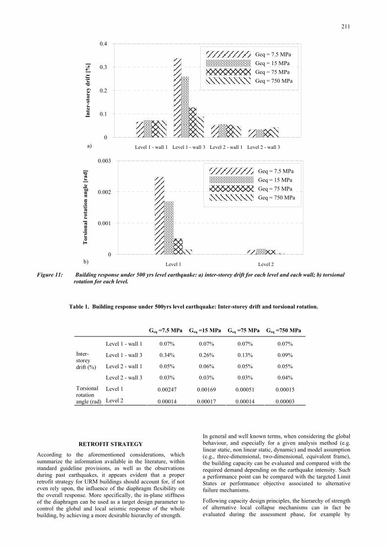
b) Figure 11: Building response under 500 yrs level earthquake: a) inter-storey drift for each level and each wall; b) torsional
rotation for each level.
Table 1. Building response under 500yrs level earthquake: Inter-storey drift and torsional rotation.
Geq =7.5 MPa Geq =15 MPa Geq =75 MPa Geq =750 MPa
Level 1 - wall 1 0.07% 0.07% 0.07% 0.07%
Level 1 - wall 3 0.34% 0.26% 0.13% 0.09%
Level 2 - wall 1 0.05% 0.06% 0.05% 0.05%
Inter-storey drift (%)
Level 2 - wall 3 0.03% 0.03% 0.03% 0.04%
Level 1 0.00247 0.00169 0.00051 0.00015 Torsional rotation angle (rad) Level 2 0.00014 0.00017 0.00014 0.00003
RETROFIT STRATEGY
According to the aforementioned considerations, which summarize the information available in the literature, within standard guideline provisions, as well as the observations during past earthquakes, it appears evident that a proper retrofit strategy for URM buildings should account for, if not even rely upon, the influence of the diaphragm flexibility on the overall response. More specifically, the in-plane stiffness of the diaphragm can be used as a target design parameter to control the global and local seismic response of the whole building, by achieving a more desirable hierarchy of strength.
In general and well known terms, when considering the global behaviour, and especially for a given analysis method (e.g. linear static, non linear static, dynamic) and model assumption (e.g., three-dimensional, two-dimensional, equivalent frame), the building capacity can be evaluated and compared with the required demand depending on the earthquake intensity. Such a performance point can be compared with the targeted Limit States or performance objective associated to alternative failure mechanisms.
Following capacity design principles, the hierarchy of strength of alternative local collapse mechanisms can in fact be evaluated during the assessment phase, for example by
212
evaluating the associated collapse factors (Lagomarsino et al. 1999) and relating them to the equivalent base shear and then to the peak ground acceleration (of a spectrum compatible record) which would cause that collapse. Furthermore, since each mode can be triggered by either excessive displacement, excessive acceleration, or a combination of the above, Limit States (damage levels) associated to each mode should be defined and compared against.
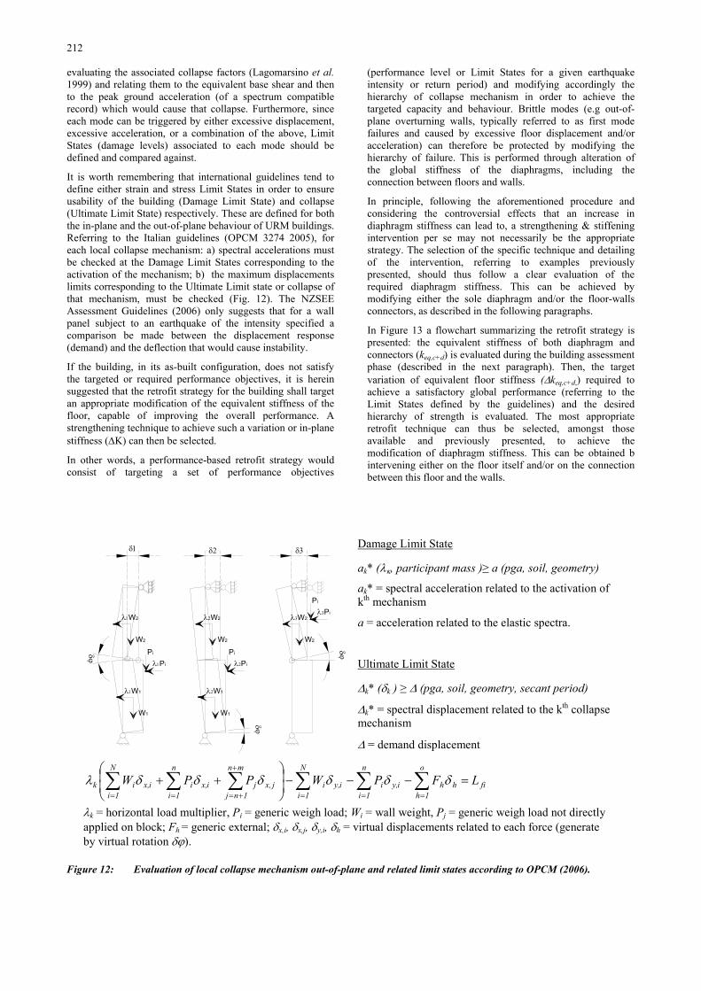
It is worth remembering that international guidelines tend to define either strain and stress Limit States in order to ensure usability of the building (Damage Limit State) and collapse (Ultimate Limit State) respectively. These are defined for both the in-plane and the out-of-plane behaviour of URM buildings. Referring to the Italian guidelines (OPCM 3274 2005), for each local collapse mechanism: a) spectral accelerations must be checked at the Damage Limit States corresponding to the activation of the mechanism; b) the maximum displacements limits corresponding to the Ultimate Limit state or collapse of that mechanism, must be checked (Fig. 12). The NZSEE Assessment Guidelines (2006) only suggests that for a wall panel subject to an earthquake of the intensity specified a comparison be made between the displacement response (demand) and the deflection that would cause instability.
If the building, in its as-built configuration, does not satisfy the targeted or required performance objectives, it is herein suggested that the retrofit strategy for the building shall target an appropriate modification of the equivalent stiffness of the floor, capable of improving the overall performance. A strengthening technique to achieve such a variation or in-plane stiffness (∆K) can then be selected.
In other words, a performance-based retrofit strategy would consist of targeting a set of performance objectives
(performance level or Limit States for a given earthquake intensity or return period) and modifying accordingly the hierarchy of collapse mechanism in order to achieve the targeted capacity and behaviour. Brittle modes (e.g out-of-plane overturning walls, typically referred to as first mode failures and caused by excessive floor displacement and/or acceleration) can therefore be protected by modifying the hierarchy of failure. This is performed through alteration of the global stiffness of the diaphragms, including the connection between floors and walls.
In principle, following the aforementioned procedure and considering the controversial effects that an increase in diaphragm stiffness can lead to, a strengthening & stiffening intervention per se may not necessarily be the appropriate strategy. The selection of the specific technique and detailing of the intervention, referring to examples previously presented, should thus follow a clear evaluation of the required diaphragm stiffness. This can be achieved by modifying either the sole diaphragm and/or the floor-walls connectors, as described in the following paragraphs.
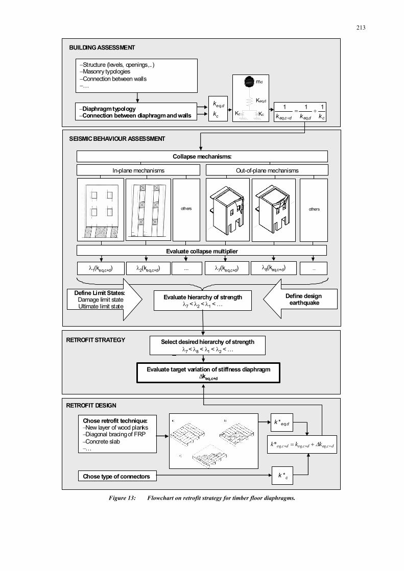
In Figure 13 a flowchart summarizing the retrofit strategy is presented: the equivalent stiffness of both diaphragm and connectors (keq,c+d) is evaluated during the building assessment phase (described in the next paragraph). Then, the target variation of equivalent floor stiffness (∆keq,c+d,) required to achieve a satisfactory global performance (referring to the Limit States defined by the guidelines) and the desired hierarchy of strength is evaluated. The most appropriate retrofit technique can thus be selected, amongst those available and previously presented, to achieve the modification of diaphragm stiffness. This can be obtained b intervening either on the floor itself and/or on the connection between this floor and the walls.
W1
Pi
λ1Pi
λ1W1
W2
λ1W2
W1
λ2W1
W2
λ2W2
W2
λ3W2
δϕ
δϕ
δϕPi
λ2Pi
Pi
λ3Pi
δ1 δ2 δ3Damage Limit State
ak* (λκ, participant mass )≥ a (pga, soil, geometry)
ak* = spectral acceleration related to the activation of kth mechanism
a = acceleration related to the elastic spectra.
Ultimate Limit State
∆k* (δk ) ≥ ∆ (pga, soil, geometry, secant period)
∆k* = spectral displacement related to the kth collapse mechanism
∆ = demand displacement
fi
o
1hhh
n
1iiy,i
N
1iiy,i
mn
1njjx,j
n
1iix,i
N
1iix,ik LFPWPPW =−−−⎟
⎟⎠
⎞⎜⎜⎝
⎛++ ∑∑∑∑∑∑
===
+
+===
δδδδδδλ
λk = horizontal load multiplier, Pi = generic weigh load; Wi = wall weight, Pj = generic weigh load not directly applied on block; Fh = generic external; δx,i, δx,j, δy,i, δh = virtual displacements related to each force (generate by virtual rotation δϕ).
Figure 12: Evaluation of local collapse mechanism out-of-plane and related limit states according to OPCM (2006).
213
BUILDING ASSESSMENT
SEISMIC BEHAVIOUR ASSESSMENT
RETROFIT STRATEGY
Evaluate target variation of stiffness diaphragm∆keq,c+d
RETROFIT DESIGN
Chose retrofit technique:−New layer of wood planks−Diagonal bracing of FRP−Concrete slab−…
Chose type of connectors
c
d,eq
k
k
c*k
d,eq*k
Keq,d
Kc Kc
md
λ1(keq,c+d) λ2(keq,c+d) ...
others others
Evaluate collapse multiplier
... λ7(keq,c+d) λ8(keq,c+d)
In-plane mechanisms Out-of-plane mechanisms
Collapse mechanisms:
Evaluate hierarchy of strengthλ7 < λ2 < λ1 < …
Define Limit States:Damage limit stateUltimate limit state
Define design earthquake
Select desired hierarchy of strengthλ7 < λ8 < λ1 < λ2 < …
cd,eqdc,eq kkk111 +=
+
−Diaphragm typology−Connection between diaphragm and walls
−Structure (levels, openings,..)−Masonry typologies−Connection between walls−…
dc,eqdc,eqdc,eq kk*k +++ += ∆
Figure 13: Flowchart on retrofit strategy for timber floor diaphragms.

214
EVALUATION OF DIAPHRAGM STIFFNESS
As illustrated in Figure 14 the overall stiffness of the floor unit, which controls the out-of-plane displacement of the wall units, is given by the contribution of the in-plane stiffness of the sole diaphragm (keq,d) and the stiffness of floor-wall shear connectors (kc). The two systems (diaphragm and connectors) are thus in series, the total deformation (δTOT) of the diaphragm being given by the sum of the two contributions:
dcTOT δδδ += (1)
Where δc = displacement due to stiffness of shear connectors; δd = displacement due to diaphragm stiffness. In the ideal case of rigid connectors (i.e. kc ∞) the overall deformation is only due to the internal diaphragm stiffness. Similarly, when assuming a rigid diaphragm (i.e. keq,d ∞), only the connectors stiffness contributes. The equivalent stiffness of the entire floor system (keq,c+d), which ultimately should be used in the assessment, design and retrofit analysis, is thus given by the combination of both contributions as follows:
cdeqdceq kkk111
,,+=
+
(2)
Focusing on the diaphragm-only stiffness (from here on simply referred to as diaphragm stiffness) it is fundamental to be able to evaluate an equivalent stiffness, before and after the retrofit intervention, depending on the different floor types used in construction practice. When referring to the as-built configurations, some analytical procedures are available in literature and are typically adopted by international guidelines on the seismic rehabilitation of buildings. In the next paragraph, a comparison between the different approaches provided by these guidelines is provided. On the other hand,
the prediction of the expected stiffness associated to alternative retrofit solutions is a more complex task, which requires further information based on both numerical and experimental investigations.
Analytical evaluation of diaphragm-only stiffness
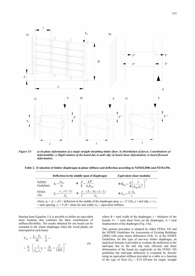
The diaphragm in-plane stiffness of timber floors can be evaluated by analysing the contribution to the in-plane deformation under simple loading conditions (Fig. 15a). Referring to a single straight sheathing, (typically consisting of 20-50 mm thick and 100-200 mm wide boards) nailed in a single layer at right angles to the cross beams, the overall flexibility can be evaluated by assuming three different contributions (Eq. 3): the flexural deformation of the single board, δ′, (Fig. 15d), the shear deformation of the single board, δ′′, (Fig. 15c), and the rigid rotation of the board due to nail slip, δ′′′, (Fig. 15b).
lFEI
lFGAsk
F
nser
⋅⎟⎟⎠
⎞⎜⎜⎝
⎛⋅+⋅+⋅=
=++=
122'
''''''2χ
δδδδ (3)
where F’/kser = nail slip resulting from the shear force F ( nsFiF ⋅⋅=⋅ '2 ); kser = nail deformability that can be determined with experimental tests or by using some empirical equations (ENV 1995-1-1 2004); χ = shear factor; G = shear modulus of timber planks; E = flexural modulus parallel to the grain of timber planks; A = area of plank section; I = moment of inertia of plank section; l = wheelbase between beams; sn = nail spacing.
kc →∞
Actualbehaviour
Diaphragmcontributionbehaviour
Connectorscontributionbehaviour
keq,d+c
Equivalentbehaviour
kd,eq →∞
kc
keq,d
Figure 14: Schematic contributions of connectors and diaphragm stiffness to the overall floor system stiffness.
215
F’
F’
F’
F’
F
FT
l
B
L
∆
sn
δ’ δ’’’δ’’
F F F
l l l
a) b)
c) d) e)
Figure 15: a) In-plane deformation of a single straight sheathing timber floor. b) Distribution of forces. Contributions of
deformability: c) Rigid rotation of the board due to nails slip; d) board shear deformation; e) board flexural deformation.
Table 2. Evaluation of timber diaphragm in-plane stiffness and deflection according to NZSEE2006 and FEMA356.
Deflection in the middle span of diaphragm Equivalent shear modulus
NZSEE Guidelines s
Lenh 2=∆
sernks'LF
=2∆
1
2
−
⎟⎟⎠
⎞⎜⎜⎝
⎛=
nsereq
skl
AG χ
FEMA 356 d
yy G
)/L(v 2⋅=∆
d
T
G)/L()B/F( 2
2⋅
=∆
tGG d
eq⋅
=χ
where ∆h = ∆y = ∆/2 = deflection in the middle of the diaphragm span; en = F’/(2kser) = nail slip; s = sn = nails spacing; νy = FT/B = shear for unit width; Gd = equivalent stiffness.
Starting from Equation 3 it is possible to define an equivalent shear modulus that combines the three contributions of stiffness/flexibility. The results obtained for one board can be extended to the whole diaphragm when the wood planks are interrupted at each beam:
12
2 12
−
⎟⎟⎠
⎞⎜⎜⎝
⎛+
χ+⋅
χ=
=∆
⋅⋅χ
=
EIl
GAskl
A
LBt
FG
nser
Teq
(4)
where B = total width of the diaphragm; t = thickness of the boards; FT = total shear force on the diaphragm; ∆ = total displacement of the diaphragm (Fig. 15a).
This general procedure is adopted by either FEMA 356 and the NZSEE Guidelines for Assessment of Existing Buildings (2006) with some minor differences (Tab. 2): in the NZSEE Guidelines, for this type of one-way timber diaphragm, an analytical formula is provided to evaluate the deflection in the mid-span due to the nail slip only (flexural and shear deformation of the board are neglected); in the FEMA 356 guidelines the mid-span deflection is evaluated by directly using an equivalent stiffness provided in a table as a function of the type of floor (Gd = 0.35 kN/mm for single, straight

216
sheathing). Figure 16 displays a comparison of results achievable by using the mentioned guidelines.

217
400 600 800 1000
Joists spacing[mm]
0
10
20
30
Equ
ival
ent s
hear
mod
ulus
Geq
[MPa
]
FEMA 356NZSEE GuidelinesEquation 4
Dn = 6 mm
Dn = 4 mm
Dn = 3 mm
t = 20 mm
400 600 800 1000
Joists spacing[mm]
0
10
20
30
Equ
ival
ent s
hear
mod
ulus
Geq
[MPa
]
FEMA 356NZSEE GuidelinesEquation 4
Dn = 6 mm
Dn = 4 mm
Dn = 3 mm
t = 30 mm
400 600 800 1000
Joists spacing[mm]
0
10
20
30
Equ
ival
ent s
hear
mod
ulus
Geq
[MPa
]
FEMA 356NZSEE GuidelinesEquation 4
sn = 150 mm
sn = 130 mm
sn = 110 mm
t = 30 mmDn = 3 mm
Figure 16: Comparison between equivalent shear modulus Geq evaluated according to the NZSEE Guidelines, FEMA 356
and Eq. 4. a, b) Influence of nails diameter (Dn); and c) Influence of distance between nails (sn).
a) b) c)
Figure 17: Different dispositions of wood planks: a) Configuration 1; b) Configuration 2; and c) Configuration 3.
218
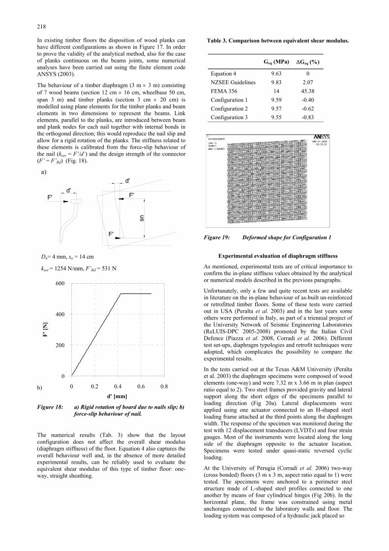
In existing timber floors the disposition of wood planks can have different configurations as shown in Figure 17. In order to prove the validity of the analytical method, also for the case of planks continuous on the beams joints, some numerical analyses have been carried out using the finite element code ANSYS (2003).
The behaviour of a timber diaphragm (3 m × 3 m) consisting of 7 wood beams (section 12 cm × 16 cm, wheelbase 50 cm, span 3 m) and timber planks (section 3 cm × 20 cm) is modelled using plane elements for the timber planks and beam elements in two dimensions to represent the beams. Link elements, parallel to the planks, are introduced between beam and plank nodes for each nail together with internal bonds in the orthogonal direction; this would reproduce the nail slip and allow for a rigid rotation of the planks. The stiffness related to these elements is calibrated from the force-slip behaviour of the nail (kser = F’/d’) and the design strength of the connector (F’ = F’Rd) (Fig. 18).
a)
d'F'
d'
F'
F'
sn
Dn= 4 mm, sn = 14 cm
kser = 1254 N/mm, F’Rd = 531 N
0 0.2 0.4 0.6 0.8
d' [mm]
0
200
400
600
F' [N
]
b)
Figure 18: a) Rigid rotation of board due to nails slip; b)
force-slip behaviour of nail.
The numerical results (Tab. 3) show that the layout configuration does not affect the overall shear modulus (diaphragm stiffness) of the floor. Equation 4 also captures the overall behaviour well and, in the absence of more detailed experimental results, can be reliably used to evaluate the equivalent shear modulus of this type of timber floor: one-way, straight sheathing.
Table 3. Comparison between equivalent shear modulus.
Figure 19: Deformed shape for Configuration 1
Experimental evaluation of diaphragm stiffness
As mentioned, experimental tests are of critical importance to confirm the in-plane stiffness values obtained by the analytical or numerical models described in the previous paragraphs.
Unfortunately, only a few and quite recent tests are available in literature on the in-plane behaviour of as-built un-reinforced or retrofitted timber floors. Some of these tests were carried out in USA (Peralta et al. 2003) and in the last years some others were performed in Italy, as part of a triennial project of the University Network of Seismic Engineering Laboratories (ReLUIS-DPC 2005-2008) promoted by the Italian Civil Defence (Piazza et al. 2008, Corradi et al. 2006). Different test set-ups, diaphragm typologies and retrofit techniques were adopted, which complicates the possibility to compare the experimental results.
In the tests carried out at the Texas A&M University (Peralta et al. 2003) the diaphragm specimens were composed of wood elements (one-way) and were 7.32 m x 3.66 m in plan (aspect ratio equal to 2). Two steel frames provided gravity and lateral support along the short edges of the specimens parallel to loading direction (Fig 20a). Lateral displacements were applied using one actuator connected to an H-shaped steel loading frame attached at the third points along the diaphragm width. The response of the specimen was monitored during the test with 12 displacement transducers (LVDTs) and four strain gauges. Most of the instruments were located along the long side of the diaphragm opposite to the actuator location. Specimens were tested under quasi-static reversed cyclic loading.
At the University of Perugia (Corradi et al. 2006) two-way (cross bonded) floors (3 m x 3 m, aspect ratio equal to 1) were tested. The specimens were anchored to a perimeter steel structure made of L-shaped steel profiles connected to one another by means of four cylindrical hinges (Fig 20b). In the horizontal plane, the frame was constrained using metal anchorages connected to the laboratory walls and floor. The loading system was composed of a hydraulic jack placed so
Geq (MPa) ∆Geq (%)
Equation 4 9.63 0 NZSEE Guidelines 9.83 2.07 FEMA 356 14 45.38 Configuration 1 9.59 -0.40 Configuration 2 9.57 -0.62 Configuration 3 9.55 -0.83

219
a) d)
b) e)
c) f)
Figure 20: Experimental tests on as-built and retrofit timber floor. a) Peralta et al. 2003; b) Corradi et al. 2006; c) Piazza et
al. 2008; Test results for single straight sheathing diaphragm: d) Peralta et al. 2003; e) Corradi et al. 2006; and f) Piazza et al. 2008.
that it applied a force acting on the steel structure in the plane of the floor in two different directions (parallel and perpendicular to the wood beams). Three inductive traducers (LVDTs) were applied to each floor sample: two lying along the two diagonals and the third in the direction of the applied shear force. Cyclic test were carried out.
At the University of Trento, monotonic tests on small size floor specimen (1 m x 2 m) and cyclic tests on real size floor specimens (one-way, 4 m x 5 m, aspect ratio equal to 1.25) were performed (Piazza et al. 2008). The floor specimen was linked to the laboratory reaction floor by means of two external hinges (Fig. 20c). The hinges were positioned centrally at the neutral axis level in order to allow free in-plane deformation of the diaphragm. An almost uniformly distributed horizontal load was applied to the floor in order to reproduce the transmission of seismic forces through the floor.
Observing the experimental results (Fig. 20d, 20e, 20f) it is worth noting that, due to the non-linear shear force vs. displacement (or diagonal deformation) response of the
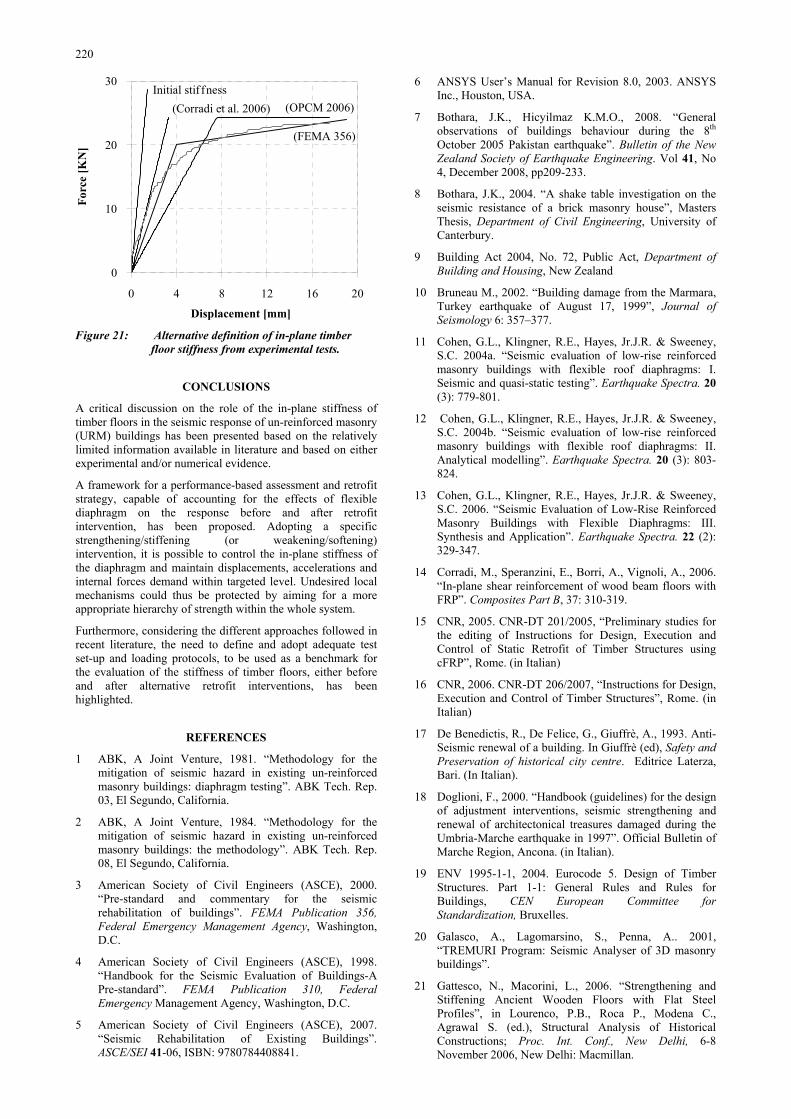
diaphragm, the value of in-plane-stiffness derived by each test is strongly affected by the definition of floor stiffness adopted. A proper evaluation of the stiffness to be adopted in the analysis of the overall building is of critical importance for both the as-built and retrofitted configuration. Alternative approaches have so far being adopted, as summarized in Figure 21, where a generic experimental curve is used. Initial elastic stiffness related to the first part of the curve, a secant stiffness at 1/3 of the maximum load (Corradi et al. 2006) or secant stiffness obtained by equivalent areas (OPCM 2005). Referring to a generic experimental curve it is possible to note that depending on different definitions of stiffness it is possible to come out with very different values. It is, therefore, particularly important that a proper definition of the stiffness is adopted in the calculation, depending on the predicted different collapse mechanisms and limit states.
220
0 4 8 12 16 20
Displacement [mm]
0
10
20
30Fo
rce
[KN
]Initial stif fness
(Corradi et al. 2006) (OPCM 2006)
(FEMA 356)
Figure 21: Alternative definition of in-plane timber
floor stiffness from experimental tests.
CONCLUSIONS
A critical discussion on the role of the in-plane stiffness of timber floors in the seismic response of un-reinforced masonry (URM) buildings has been presented based on the relatively limited information available in literature and based on either experimental and/or numerical evidence.
A framework for a performance-based assessment and retrofit strategy, capable of accounting for the effects of flexible diaphragm on the response before and after retrofit intervention, has been proposed. Adopting a specific strengthening/stiffening (or weakening/softening) intervention, it is possible to control the in-plane stiffness of the diaphragm and maintain displacements, accelerations and internal forces demand within targeted level. Undesired local mechanisms could thus be protected by aiming for a more appropriate hierarchy of strength within the whole system.
Furthermore, considering the different approaches followed in recent literature, the need to define and adopt adequate test set-up and loading protocols, to be used as a benchmark for the evaluation of the stiffness of timber floors, either before and after alternative retrofit interventions, has been highlighted.
REFERENCES
1 ABK, A Joint Venture, 1981. “Methodology for the mitigation of seismic hazard in existing un-reinforced masonry buildings: diaphragm testing”. ABK Tech. Rep. 03, El Segundo, California.
2 ABK, A Joint Venture, 1984. “Methodology for the mitigation of seismic hazard in existing un-reinforced masonry buildings: the methodology”. ABK Tech. Rep. 08, El Segundo, California.
3 American Society of Civil Engineers (ASCE), 2000. “Pre-standard and commentary for the seismic rehabilitation of buildings”. FEMA Publication 356, Federal Emergency Management Agency, Washington, D.C.
4 American Society of Civil Engineers (ASCE), 1998. “Handbook for the Seismic Evaluation of Buildings-A Pre-standard”. FEMA Publication 310, Federal Emergency Management Agency, Washington, D.C.
5 American Society of Civil Engineers (ASCE), 2007. “Seismic Rehabilitation of Existing Buildings”. ASCE/SEI 41-06, ISBN: 9780784408841.
6 ANSYS User’s Manual for Revision 8.0, 2003. ANSYS Inc., Houston, USA.
7 Bothara, J.K., Hicyilmaz K.M.O., 2008. “General observations of buildings behaviour during the 8th October 2005 Pakistan earthquake”. Bulletin of the New Zealand Society of Earthquake Engineering. Vol 41, No 4, December 2008, pp209-233.
8 Bothara, J.K., 2004. “A shake table investigation on the seismic resistance of a brick masonry house”, Masters Thesis, Department of Civil Engineering, University of Canterbury.
9 Building Act 2004, No. 72, Public Act, Department of Building and Housing, New Zealand
10 Bruneau M., 2002. “Building damage from the Marmara, Turkey earthquake of August 17, 1999”, Journal of Seismology 6: 357–377.
11 Cohen, G.L., Klingner, R.E., Hayes, Jr.J.R. & Sweeney, S.C. 2004a. “Seismic evaluation of low-rise reinforced masonry buildings with flexible roof diaphragms: I. Seismic and quasi-static testing”. Earthquake Spectra. 20 (3): 779-801.
12 Cohen, G.L., Klingner, R.E., Hayes, Jr.J.R. & Sweeney, S.C. 2004b. “Seismic evaluation of low-rise reinforced masonry buildings with flexible roof diaphragms: II. Analytical modelling”. Earthquake Spectra. 20 (3): 803-824.
13 Cohen, G.L., Klingner, R.E., Hayes, Jr.J.R. & Sweeney, S.C. 2006. “Seismic Evaluation of Low-Rise Reinforced Masonry Buildings with Flexible Diaphragms: III. Synthesis and Application”. Earthquake Spectra. 22 (2): 329-347.
14 Corradi, M., Speranzini, E., Borri, A., Vignoli, A., 2006. “In-plane shear reinforcement of wood beam floors with FRP”. Composites Part B, 37: 310-319.
15 CNR, 2005. CNR-DT 201/2005, “Preliminary studies for the editing of Instructions for Design, Execution and Control of Static Retrofit of Timber Structures using cFRP”, Rome. (in Italian)
16 CNR, 2006. CNR-DT 206/2007, “Instructions for Design, Execution and Control of Timber Structures”, Rome. (in Italian)
17 De Benedictis, R., De Felice, G., Giuffrè, A., 1993. Anti-Seismic renewal of a building. In Giuffrè (ed), Safety and Preservation of historical city centre. Editrice Laterza, Bari. (In Italian).
18 Doglioni, F., 2000. “Handbook (guidelines) for the design of adjustment interventions, seismic strengthening and renewal of architectonical treasures damaged during the Umbria-Marche earthquake in 1997”. Official Bulletin of Marche Region, Ancona. (in Italian).
19 ENV 1995-1-1, 2004. Eurocode 5. Design of Timber Structures. Part 1-1: General Rules and Rules for Buildings, CEN European Committee for Standardization, Bruxelles.
20 Galasco, A., Lagomarsino, S., Penna, A.. 2001, “TREMURI Program: Seismic Analyser of 3D masonry buildings”.
21 Gattesco, N., Macorini, L., 2006. “Strengthening and Stiffening Ancient Wooden Floors with Flat Steel Profiles”, in Lourenco, P.B., Roca P., Modena C., Agrawal S. (ed.), Structural Analysis of Historical Constructions; Proc. Int. Conf., New Delhi, 6-8 November 2006, New Delhi: Macmillan.
221
22 Gattesco, N., Macorini, L., Benussi, F. 2007. “Retrofit of wooden floors for the seismic adjustment of historical buildings with high reversible techniques. Seismic Engineering in Italy”; Proc. Of the XII National Conference, Pisa, 10-14 June 2007, full paper on CD (in Italian).
23 Giuriani, E., Marini, A. & Plizzari, G. 2002. “Shear behaviour of wooden floors strengthened by stud connected wooden planks”, Technical Report n. 7, Department of Civil Engineering, University of Brescia.
24 Lagomarsino, S. & Podestà, S. 1999. “Methodologies for the vulnerability analyses of churches. Seismic Engineering in Italy”; Proc. Of the IX National Conference, Turin, 20-23 September 1999, Turin (Medi@SOFT), (in Italian).
25 Lemme A., Martinelli A., Podestà S., 2008. ”2002 Molise Earthquake: from the emergency to the reconstruction. Masonry buildings”. Dei – Tipografia del genio civile, Roma (in Italian).
26 OPCM 3274, 2005. “Code for the seismic design, assessment and retrofitting of buildings (Appendix 2). Ordinance of the Prime Minister”, n. 3274 (20 March 2003) modified by n. 3431 (3 May 2005). (in Italian).
27 NZS 1170.5:2004 - Structural Design Actions - Part 5 : Earthquake actions – New Zealand.
28 Paquette, J. & Bruneau, M. 2006. “Pseudo-dynamic testing of un-reinforced masonry building with flexible diaphragm and comparison with existing procedures”. Constructions and Building Materials 20: 220-228.
29 Peralta, D. F., Bracci, J. M. & Hueste, M. D. 2003. “Seismic performance of rehabilitated wood diaphragms, Mid-America Earthquake Centre”, University of Illinois at Urbana-Champaign, CD Release 03-01.
30 Peralta, D. F., Bracci, J. M., & Hueste, M. B. D. 2004. “Seismic behaviour of wood diaphragms in pre-1950s un-reinforced masonry buildings”. Journal of Structural Engineering, 130(12): 2040-2050. Retrieved January 31, 2008, from Earthquake Engineering Abstracts database.
31 Piazza M., Baldessari C., Tomasi R., Acler E., 2008. “Behaviour of refurbished timber floors characterized by different in-plane stiffness”. Private communication.
32 Recommendations of a NZSEE Study Group, 2006. “Assessment and Improvement of the Structural Performance of Buildings in Earthquake”, NZSEE.
33 Tena-Colunga, A. 1992. “Seismic evaluation of un-reinforced masonry structures with flexible diaphragms”, Earthquake Spectra, 8(2): 305-318.
34 Tena-Colunga, A., Abrams, D.P. 1995. “Simplified 3-D Dynamic Analysis of Structures with Flexible Diaphragms”, Earthquake Engineering and Structural Dynamics, 24(2): 221-232.
35 Tena-Colunga, A., Abrams, D.P. 1996. “Seismic Behaviour of Structures with Flexible Diaphragms”, ASCE Journal of Structural Engineering, 122(4): 439-445.
36 TREMA Project 2006. “Technologies for the Reduction of seismic Effects on Architectural Manufactures”, www.unibas.it/trerem/index.htm.