Embed Size (px)
Citation preview
Germanischer Lloyd AG Vorsetzen 32/35 D-20459 Hamburg www.germanlloyd.org/aeneas.html
TraffGo GmbH Grabenstrasse 132 D-47057 Duisburg www.traffgo.com
Evacuation analysis
������-Dampfer
Modelling, Simulation, Analysis
Manual for the seminar „AENEAS“ on 1st of. July 2002 in Ham-
burg
D
A
M
P
F
E
R
emonstration
pplication
odel for
assenger
low in
gress
outes

Evakuierungsanalyse mit ������
© 2002 by TraffGo GmbH, Germanischer Lloyd AG 1
AENEAS DAMPFER
������
Advice ........................................................................................................................................... 1
1 Introduction........................................................................................................................... 2
1.1 Status quo of technology ............................................................................................. 2
1.2 Basics of Simulation..................................................................................................... 3
1.3 AENEAS-Dampfer ....................................................................................................... 4
2 Conceptual formulation......................................................................................................... 6
3 Allocation of People.............................................................................................................. 7
4 „Clearance“ of the Plan......................................................................................................... 8
4.1 Several Decks in several Data Files ............................................................................ 8
4.2 Clearance of useless Elements ................................................................................... 9
4.3 Inscription .................................................................................................................... 9
4.4 Decamping of Lines ................................................................................................... 10
4.5 Editing Time............................................................................................................... 10
5 Allocation of Attributes........................................................................................................ 11
6 Discretising......................................................................................................................... 12
6.1 Import and Edit .......................................................................................................... 12
6.2 Stairways ................................................................................................................... 14
6.3 Define Routes ............................................................................................................ 15
6.4 Allocation of Persons ................................................................................................. 17
6.5 Editing Time............................................................................................................... 18
7 Analysis .............................................................................................................................. 19
7.1 Basics ........................................................................................................................ 19
7.2 Mean Calculation, Case 1.......................................................................................... 20
7.3 Single Calculation, Case 1......................................................................................... 21
7.4 Editing Time............................................................................................................... 25
7.5 Case 3 in Comparison ............................................................................................... 25
8 Evaluation........................................................................................................................... 27
9 Literature ............................................................................................................................ 28
10 Internet ............................................................................................................................... 28

Evakuierungsanalyse mit ������
© 2002 by TraffGo GmbH, Germanischer Lloyd AG 1
AENEAS DAMPFER
��� �
Evacuation models like AENEAS, who represent specific topics of human behaviour in one single
software, cannot seize all the physical, psychological and social measures. The Basis to model-
ling are especially the individual demand of space and the velocity that is to be reached under
various environmental conditions e.g. the density of people ( compare fundamental diagram)
Evakuierungsanalyse mit ������
© 2002 by TraffGo GmbH, Germanischer Lloyd AG 2
AENEAS DAMPFER
� ��������� ��
This manuscript is part of the manuals for the „AENEAS“-seminar, which was held combined by
the TraffGo GmbH and the Germanischer Lloyd AG on the 1st of July 2002 in Hamburg. The in-
tention of this seminar was to demonstrate the procedure of the evacuation analysis (who meets
the IMO requirements) of a passenger ship by means of a simple example. The sample was con-
structed as simple as possible but also as complex as necessary. It was the intention to include
on the one hand simple geometry that is straightforward and on the other hand all the essential
mechanisms of an evacuation.
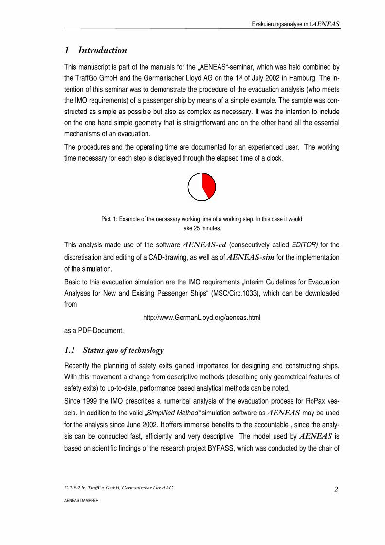
The procedures and the operating time are documented for an experienced user. The working
time necessary for each step is displayed through the elapsed time of a clock.
�
Pict. 1: Example of the necessary working time of a working step. In this case it would
take 25 minutes.
This analysis made use of the software �������� (consecutively called EDITOR) for the
discretisation and editing of a CAD-drawing, as well as of �������� � for the implementation
of the simulation.
Basic to this evacuation simulation are the IMO requirements „Interim Guidelines for Evacuation
Analyses for New and Existing Passenger Ships“ (MSC/Circ.1033), which can be downloaded
from
http://www.GermanLloyd.org/aeneas.html
as a PDF-Document.
��� ��������������������
Recently the planning of safety exits gained importance for designing and constructing ships.
With this movement a change from descriptive methods (describing only geometrical features of
safety exits) to up-to-date, performance based analytical methods can be noted.
Since 1999 the IMO prescribes a numerical analysis of the evacuation process for RoPax ves-
sels. In addition to the valid „Simplified Method“ simulation software as ������may be used
for the analysis since June 2002. It.offers immense benefits to the accountable , since the analy-
sis can be conducted fast, efficiently and very descriptive The model used by ������ is
based on scientific findings of the research project BYPASS, which was conducted by the chair of
Evakuierungsanalyse mit ������
© 2002 by TraffGo GmbH, Germanischer Lloyd AG 3
AENEAS DAMPFER
Physics of Transportation and Traffic under the direction of Prof. Michael Schreckenberg at the
Gerhard-Mercator University Duisburg.
It was implemented by the TraffGo GmbH in cooperation with the Germanischer Lloyd onto the
software ������, which is especially suited for the needs of the maritime industry.
��� ��� ����� ����� ��
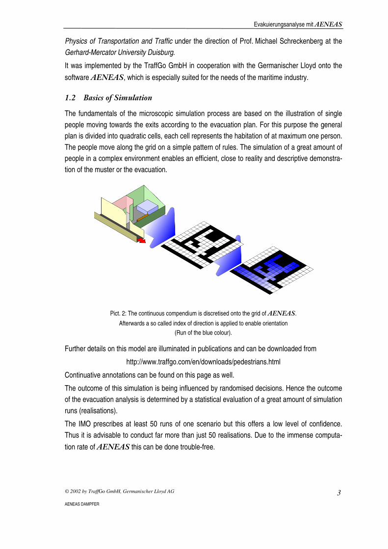
The fundamentals of the microscopic simulation process are based on the illustration of single
people moving towards the exits according to the evacuation plan. For this purpose the general
plan is divided into quadratic cells, each cell represents the habitation of at maximum one person.
The people move along the grid on a simple pattern of rules. The simulation of a great amount of
people in a complex environment enables an efficient, close to reality and descriptive demonstra-
tion of the muster or the evacuation.
�
Pict. 2: The continuous compendium is discretised onto the grid of ������.
Afterwards a so called index of direction is applied to enable orientation
(Run of the blue colour).
Further details on this model are illuminated in publications and can be downloaded from
http://www.traffgo.com/en/downloads/pedestrians.html
Continuative annotations can be found on this page as well.
The outcome of this simulation is being influenced by randomised decisions. Hence the outcome
of the evacuation analysis is determined by a statistical evaluation of a great amount of simulation
runs (realisations).
The IMO prescribes at least 50 runs of one scenario but this offers a low level of confidence.
Thus it is advisable to conduct far more than just 50 realisations. Due to the immense computa-
tion rate of ������ this can be done trouble-free.
Evakuierungsanalyse mit ������
© 2002 by TraffGo GmbH, Germanischer Lloyd AG 4
AENEAS DAMPFER
�� �������!��"��
The ������-Dampfer (compare. Pict. 3) was designed as an example, with whom all essen-
tial aspects of an evacuation analysis can be acted out comprehensively. At present an evacua-
tion analysis is only prescribed for RoPax vessels, hence this type of ship was chosen. The
������-Dampfer consists of a loading area for vehicles on the lowest deck, which can be
entered through the two ramps on rear of the vessel
For realistic plans of ships no significant additions occur, the analysis only demands a greater
expenditure of human labour.
The complete ship consists of two fire zones (Main Vertical Zones, MVZ) and four decks with the
regular width of a ship. To obtain a large density among occupants -thus creating the evacuation
scenario very pretentious- the two upper decks were chosen as very small and mainly occupied
by four people.
The second deck includes only public facilities such as restaurants, which are used as mustering
stations during an evacuation scenario. According to the IMO directives MSC/Circ.1033 the us-
age of simulation only calculates the so called Travel Time thus people can be marked as saved
when arriving at the mustering station.

Evakuierungsanalyse mit ������
© 2002 by TraffGo GmbH, Germanischer Lloyd AG 5
AENEAS DAMPFER
�
������������� ������ �������������� ������

Evakuierungsanalyse mit ������
© 2002 by TraffGo GmbH, Germanischer Lloyd AG 6
AENEAS DAMPFER
� ����"������������ ��
Through the use of numerical analysis it has to be verified for RoPax vessels that the capacity of
the lodes and the conceptual framework of the evacuation plan are sufficient to evacuate the
complete ship within 60 minutes
The composition of the population is determined by the directive MSC/Circ.1033 . Further it is
assumed that the people follow the primary escape route to the mustering station.
There are four different cases prescribed. An evacuation analysis has to be prepared for each
case.
Complete availability of the escape route
Limited availability of the escape routes
Night Case 1 Case 3
Day Case 2 Case 4
Since there is no significant difference in the procedure among the four cases, only case1 (com-
plete availability of the escape routes during night) will be examined in detail and case 3 ( limited
availability of the escape routes during night) only comparatively marginal
Evakuierungsanalyse mit ������
© 2002 by TraffGo GmbH, Germanischer Lloyd AG 7
AENEAS DAMPFER
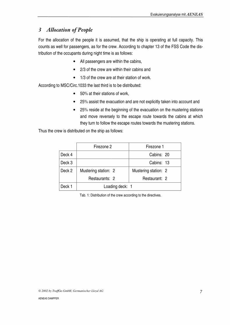
������� ����#�"�
For the allocation of the people it is assumed, that the ship is operating at full capacity. This
counts as well for passengers, as for the crew. According to chapter 13 of the FSS Code the dis-
tribution of the occupants during night time is as follows:
• All passengers are within the cabins,
• 2/3 of the crew are within their cabins and
• 1/3 of the crew are at their station of work.
According to MSC/Circ.1033 the last third is to be distributed:
• 50% at their stations of work,
• 25% assist the evacuation and are not explicitly taken into account and
• 25% reside at the beginning of the evacuation on the mustering stations
and move reversely to the escape route towards the cabins at which
they turn to follow the escape routes towards the mustering stations.
Thus the crew is distributed on the ship as follows:
Firezone 2 Firezone 1
Deck 4 Cabins: 20
Deck 3 Cabins: 13
Deck 2 Mustering station:
Restaurants:
2
2
Mustering station:
Restaurant:
2
2
Deck 1 Loading deck: 1
Tab. 1: Distribution of the crew according to the directives.

Evakuierungsanalyse mit ������
© 2002 by TraffGo GmbH, Germanischer Lloyd AG 8
AENEAS DAMPFER
$ %�������&����#���
Since the general plan is mainly based on a numerical evacuation analysis, it contains to many.
or inexpediently formatted data. For this reason it has to be cleaned up, to assure a smooth im-
port of data into ��������. The disciplined usage of layers accelerates the editing.
$�� �����!�'� ������!���( ��
Each deck must exist as a single data file. Remember to place the coordinate origins carefully in each data file. If they do not comply the stairwells will not align.
The decks are imported separately as dxf-formatted-data files into the editor. For this reason the
drawings have to be split up in separate data files according to the decks. To assure an exact
positioning of each deck one upon the other the points of origin must be redefined on the same
spot obverse to the frame muster for every single file..
�
Pict. 4: Fragmentation and alignment of the decks into separate data files.
Evakuierungsanalyse mit ������
© 2002 by TraffGo GmbH, Germanischer Lloyd AG 9
AENEAS DAMPFER
$�� ��������������������
The exact shape of a wash basin or other details of the furnishing have no impact on the outcome of the simulation and decelerate the workflow. Erase all these details!
Often CAD drawings contain elements that are excrescent for the simulation. Especially the inser-
tion of drawings of sub-suppliers inflates the plan needlessly.
Guide and drawing tools, not describing any geometry and thus not influencing the movement of
the occupants can be erased thoughtlessly. Among these -are beside the guide lines- the lines
and arrows that mark the escape routes.
Furnishing should be removed from the plan as well. Across the board one can assume that the
furnishing of the cabins is unsubstantial for the complete evacuation process. But all elements
that bias the cross sections of the escape routes ( e.g. columns, lounges) should be regarded. In
this case simple outlines are sufficient.
Consistent usage of layers abbreviates this working step considerably. Specific attributes can be
allocated to objects used as a link (e.g. door impact) and then later on be filtered out.
(see chap. 5)
$� ����� "� ��
Figures are supposed to characterise only the group of people. Erase the rest of the figures.
Alpha numerical figures in the plan are automatically interpreted as a person group by the editor.
Insofar all characters not resembling the person group should be blinded out on a separate layer
or simply erased. Especially the insertion of drawings of suppliers leads to difficulties, because
e.g. a small object was measured but still the measured value appears in the drawing.
The denotation of the cabins should be ( as in this case „Pax 4“) converted in to integer numbers,
thus 4.

Evakuierungsanalyse mit ������
© 2002 by TraffGo GmbH, Germanischer Lloyd AG 10
AENEAS DAMPFER
$�$ !���" ����) ��
In a solid wall a door cannot be identified. Separate solid elements.
In the preliminary layouts doors are often marked with the help of a impact, who is drawn onto a
solid line, that symbolizes a wall. To be able to identify a door as a passage (after dying) the solid
wall must be interrupted.
�
Pict. 5: Splitting of a solid wall at the door.
$�* �� � ��+ �
The operations described in this chapter demanded the following editing time:
Activity Time /min
Several Decks in several Data Files 5
Clearance of useless Elements 10
Inscription 5
Decamping of Lines 15
Sum 35
The use of innovative tools, that are being developed. at present , will enable a partly automation
of the editing process and reduce the efforts.

Evakuierungsanalyse mit ������
© 2002 by TraffGo GmbH, Germanischer Lloyd AG 11
AENEAS DAMPFER
* ������� �������� ,���
Different colours enable the allocation of characteristics to objects e.g. lines. Use this opportunity and thus accelerate the discretisation in the editor.
The transfer of the colour-attributes during the export of dxf data files is a function that is offered
by most commercial CAD programmes. Through the colour of the object the editor identifies ,
which object to mark and automatically allocates the correct attribute to corresponding cell. Every
colour can only reflect one single attribute . The following cell-attributes are available:
Wall : Walls and furnishing. They cannot be entered.
Door : Sills. Occupants reduce speed to a quarter while
passing the sills.
Stairs : Steps. Occupants reduce speed contingent of
whether they move up or down stairs.
Upwards : First step of a the stairs leading upwards.
Downwards : First step of the stairs leading downwards
Ignore : Elements with these attributes are being ignored
and not allocated to a cell.
The allocation of the colours to the attributes must be effective for the complete general plan, but
may differ for each shipyard or project.
�
Pict. 6: After separating the elements they can be dyed. In this case turquoise is
being ignored but yellow identified as a door
Evakuierungsanalyse mit ������
© 2002 by TraffGo GmbH, Germanischer Lloyd AG 12
AENEAS DAMPFER
- ! ���� � ��
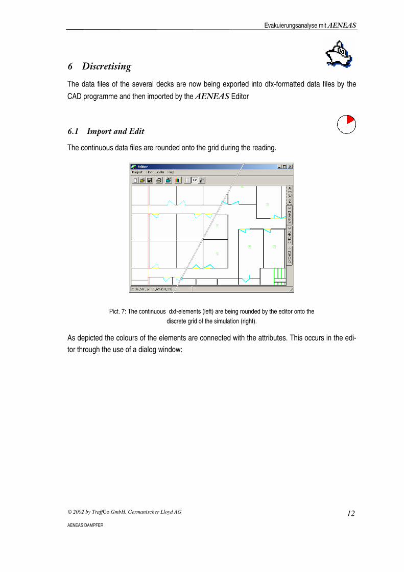
The data files of the several decks are now being exported into dfx-formatted data files by the
CAD programme and then imported by the ������ Editor
-�� ��"�������� �
The continuous data files are rounded onto the grid during the reading.
�
Pict. 7: The continuous dxf-elements (left) are being rounded by the editor onto the
discrete grid of the simulation (right).
As depicted the colours of the elements are connected with the attributes. This occurs in the edi-
tor through the use of a dialog window:

Evakuierungsanalyse mit ������
© 2002 by TraffGo GmbH, Germanischer Lloyd AG 13
AENEAS DAMPFER
�
Pict. 8: The dialog window „Color Coding“, which allocates the attributes to the
utilised colours
Now that the attributes of the objects can be identified by the colour, the editor allocates the at-
tributes to the corresponding cells.
�
Pict. 9: On the basis of the colour allocation cells receive the essential information..
Due to discretising rounding errors may appear (e.g. at the red marked door cells).
Evakuierungsanalyse mit ������
© 2002 by TraffGo GmbH, Germanischer Lloyd AG 14
AENEAS DAMPFER
Due the rounding of the continuous dfx-elements onto the discrete grid inaccuracies may occur.
For this reason the plan must be reviewed by hand and on occasion single elements edited by
hand. The editor offers a few simple tools that allow the following actions:
• Screening,
• Scrolling,
• Drafting and
• Deleting elements.
-�� ��� �.���
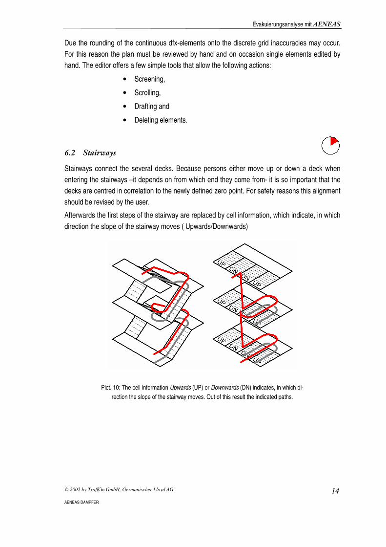
Stairways connect the several decks. Because persons either move up or down a deck when
entering the stairways –it depends on from which end they come from- it is so important that the
decks are centred in correlation to the newly defined zero point. For safety reasons this alignment
should be revised by the user.
Afterwards the first steps of the stairway are replaced by cell information, which indicate, in which
direction the slope of the stairway moves ( Upwards/Downwards)
�
Pict. 10: The cell information Upwards (UP) or Downwards (DN) indicates, in which di-
rection the slope of the stairway moves. Out of this result the indicated paths.
Evakuierungsanalyse mit ������
© 2002 by TraffGo GmbH, Germanischer Lloyd AG 15
AENEAS DAMPFER
�
�
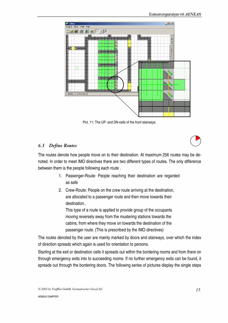
Pict. 11: The UP- and DN-cells of the front stairways.
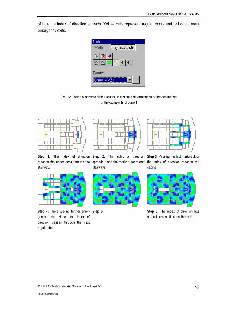
-� !� �/����
The routes denote how people move on to their destination. At maximum 256 routes may be de-
noted. In order to meet IMO directives there are two different types of routes. The only difference
between them is the people following each route .
1. Passenger-Route: People reaching their destination are regarded
as safe
2. Crew-Route: People on the crew route arriving at the destination,
are allocated to a passenger route and then move towards their
destination..
This type of a route is applied to provide group of the occupants
moving reversely away from the mustering stations towards the
cabins, from where they move on towards the destination of the
passenger route. (This is prescribed by the IMO directives)
The routes denoted by the user are mainly marked by doors and stairways, over which the index
of direction spreads which again is used for orientation to persons.
Starting at the exit or destination cells it spreads out within the bordering rooms and from there on
through emergency exits into to succeeding rooms. If no further emergency exits can be found, it
spreads out through the bordering doors. The following series of pictures display the single steps
Evakuierungsanalyse mit ������
© 2002 by TraffGo GmbH, Germanischer Lloyd AG 16
AENEAS DAMPFER
of how the index of direction spreads. Yellow cells represent regular doors and red doors mark
emergency exits.
�
Pict. 12: Dialog window to define routes, in this case determination of the destination
for the occupants of zone 1
Step 1: The index of direction
reaches the upper deck through the
stairway.
Step 2: The index of direction
spreads along the marked doors and
stairways
Step 3: Passing the last marked door
the index of direction reaches the
cabins
Step 4: There are no further emer-
gency exits. Hence the index of
direction passes through the next
regular door
Step 5
Step 6: The index of direction has
spread across all accessible cells

Evakuierungsanalyse mit ������
© 2002 by TraffGo GmbH, Germanischer Lloyd AG 17
AENEAS DAMPFER
Overall four routes are allocated in this concept:
Nr. Typ MVZ Destination
1 Pax 1 (front) Mustering station (Blue Ocean Restaurant), Deck 2, front
2 Pax 2 (abaft) Mustering station, (������ and PedGo Bar) Deck 2, abaft
3 Crew 1 (front) Stairwell, Deck 4, front
4 Crew 2 (abaft) Stairwell, Deck 4 abaft
�
�
Pict. 13: The cells of destination (orange) on Deck 2 and 4.
-�$ ������� ����#�����
The amount of people in each room is ,as depicted earlier, included in the dxf-data file in form of
a text element and automatically interpreted by the editor. The persons still have to be assigned
to their destinations and individual attributes have to be applied to them. There are two types of a
person according to the IMO directives : Passenger and crew
�
Pict. 14: The dialog window for submission of the amount of people, assigned route
and the type of person per room or defined area .

Evakuierungsanalyse mit ������
© 2002 by TraffGo GmbH, Germanischer Lloyd AG 18
AENEAS DAMPFER
The persons can either be assigned to a given rectangular area or to a room. At the beginning of
the simulation �������� � allocates them randomly on the corresponding cells of the base
-�* �� � ��+ �
: The operations described in this chapter demanded the following editing time
Activity Time /min
Import and Edit 10
Stairways 10
Define Routes 10
Allocation of Persons 15
Sum 45
Innovative tools can reduce this expenditure of labour.
Evakuierungsanalyse mit ������
© 2002 by TraffGo GmbH, Germanischer Lloyd AG 19
AENEAS DAMPFER
0 ������ �
0�� ��� ��
The decisions and parameter of the simulated persons are subject to stochastic influences. Thus
each run of simulation provides a different time frame for the evacuation process. This can also
be noted for runs starting at the same conditions. The following random decisions have an impact
on the course of the simulation
1.Option of the running direction,
2.Solving situations of conflict (several persons on one single cell),
3.Hang behind and
4.Option of the route when reaching the destination of a crew route.
At the beginning of each run the parameters of the persons along with their points of origin are
relocated to ensure a stochastically distribution among the population.
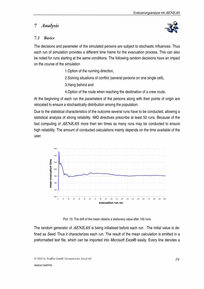
Due to the statistical characteristics of the outcome several runs have to be conducted, allowing a
statistical analysis of strong reliability. IMO directives prescribe at least 50 runs. Because of the
fast computing of ������more than ten times as many runs may be conducted to ensure
high reliability. The amount of conducted calculations mainly depends on the time available of the
user.
920
940
960
980
1000
1020
1040
1060
0 10 20 30 40 50 60 70 80 90 100 110 120 130 140 150 160 170 180 190 200
evacuation run no.
mean
evacu
ati
on
tim
e
�
Pict. 15: The drift of the mean obtains a stationary value after 100 runs
The random generator of ������ is being initialised before each run . The initial value is de-
fined as Seed. Thus it characterizes each run. The result of the mean calculation is emitted in a
preformatted text file, which can be imported into Microsoft Excel® easily. Every line denotes a

Evakuierungsanalyse mit ������
© 2002 by TraffGo GmbH, Germanischer Lloyd AG 20
AENEAS DAMPFER
single run. Along with the calculated time every seed of each evacuation run can be
read, so that single calculations may be repeated through the use of .the seed.
0�� 1���������� ��2����
The analysis of „Case 1“ of the ������-Dampfers (542 persons) demands approximately 2
minutes of computing time for 50 runs. According to MSC/Circ.1033 is that evacuation duration
relevant, that is greater than 95 % of the complete set of evacuation time. The computed running
time accounts for 17’42’’ minutes. The standard deviation of all results is 42 seconds. The follow-
ing chart can be attained from the file::
0
0,5
1
1,5
2
2,5
900 960 1020 1080 1140 1200
evacuation time
freq
uen
cy
<95%
�
Pict. 16: Distribution of the evacuation times.
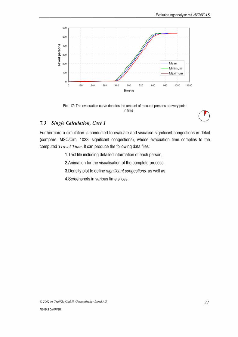
In the following chart– the evacuation curve – the amount of rescued persons at each point in
time is applied. Thereby the computed means but also the minimum and maximum values are
applied .
Evakuierungsanalyse mit ������
© 2002 by TraffGo GmbH, Germanischer Lloyd AG 21
AENEAS DAMPFER
0
100
200
300
400
500
600
0 120 240 360 480 600 720 840 960 1080 1200
time /s
saved
pers
on
s
Mean
Minimum
Maximum
�
Pict. 17: The evacuation curve denotes the amount of rescued persons at every point in time
0� � ����������� ��2����
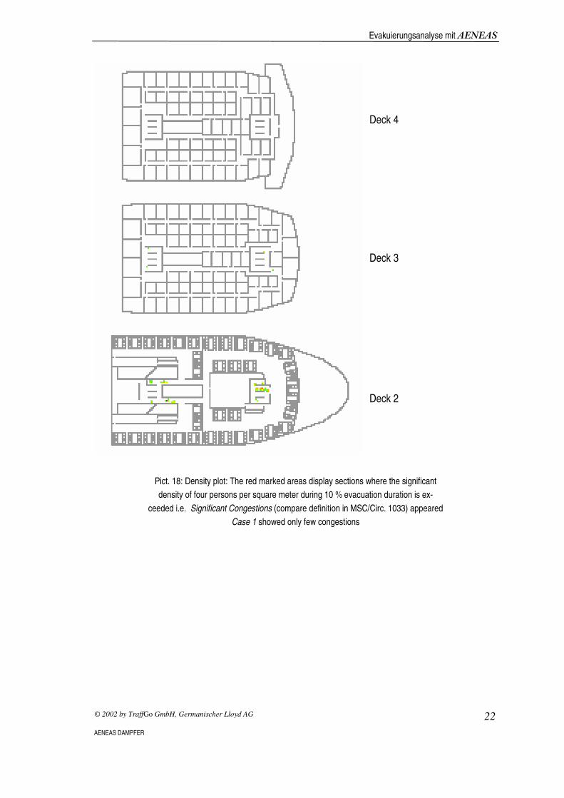
Furthermore a simulation is conducted to evaluate and visualise significant congestions in detail
(compare. MSC/Circ. 1033: significant congestions), whose evacuation time complies to the
computed Travel Time. It can produce the following data files:
1.Text file including detailed information of each person,
2.Animation for the visualisation of the complete process,
3.Density plot to define significant congestions as well as
4.Screenshots in various time slices.
Evakuierungsanalyse mit ������
© 2002 by TraffGo GmbH, Germanischer Lloyd AG 22
AENEAS DAMPFER
Deck 4
Deck 3
�
Deck 2
Pict. 18: Density plot: The red marked areas display sections where the significant
density of four persons per square meter during 10 % evacuation duration is ex-
ceeded i.e. Significant Congestions (compare definition in MSC/Circ. 1033) appeared
Case 1 showed only few congestions

Evakuierungsanalyse mit ������
© 2002 by TraffGo GmbH, Germanischer Lloyd AG 23
AENEAS DAMPFER
Using the detailed information of the files evacuation curves of every destination can be deter-
mined. From this it becomes clear that the evacuation of the fire zone up front(MVZ 1) lasts 149
seconds (=2’29“ min) longer than the zone upfront.
0
50
100
150
200
250
300
420 480 540 600 660 720 780 840 900 960 1020 1080
time /s
Pers
on
s
MVZ 1
MVZ 2, BB
MVZ 2, SB
�
Pict. 19: Evacuation curve of each mustering station

Evakuierungsanalyse mit ������
© 2002 by TraffGo GmbH, Germanischer Lloyd AG 24
AENEAS DAMPFER
Deck 4
Deck 3
Deck 2
�
Deck 1
Pict. 20: Screenshot of the simulation at the time t = 600 s.

Evakuierungsanalyse mit ������
© 2002 by TraffGo GmbH, Germanischer Lloyd AG 25
AENEAS DAMPFER
0�$ �� � ��+ �
The operations described in this chapter demanded the following editing time
Activity Time /min
Mean Calculation, Case 1 5
Single Calculation, Case 1 5
Sum 10
0�* ��� ����"�� ���
For comparison this chapter briefly addresses the results of Case 3. According to MSC/Circ.1033
this is a night time scenario and deals only with the fire zone, which has the longest evacuation
duration. In this case it is MVZ 1, the zone upfront. The capacity of the stairways is halved ac-
cording to the directives.
To be able to compare both cases, the complete ship is regarded and half of the stairwells are
inaccessible..
0
100
200
300
400
500
600
0 60 120 180 240 300 360 420 480 540 600 660 720 780 840 900 960 1020
time/s
rescu
ed
pers
on
s
Case 1, Mittelwert
Case 3, Mittelwert
�
Pict. 21: Comparison of Case 1 and Case 3.

Evakuierungsanalyse mit ������
© 2002 by TraffGo GmbH, Germanischer Lloyd AG 26
AENEAS DAMPFER
The running time of this case in accordance with MSC/Circ.1033 is 17'47“ minutes and lasts only
5 seconds longer. Thus this ship meets the directives of the IMO. If one takes a look at the
evacuation curves of both cases, it becomes clear, that the slope of Case 3 is smaller but still
both curves converge near the end. Insofar the time span is mainly affected by late reactions and
slow tempo of a few persons. But Case 3 delivers special significant congestions in the fore
stairway.
Deck 4
Deck 3
�
Deck 2
Pict. 22: Density plot of Case 3. According to MSC/Circ.1033 only the fore fire zone at
halved capacity of the stairways had to be regarded. In this case significant conges-
tion appear.

Evakuierungsanalyse mit ������
© 2002 by TraffGo GmbH, Germanischer Lloyd AG 27
AENEAS DAMPFER
3 ������� ��
According to MSC/Circ.1033 an additional safety loading of 10 minutes has to be added to the
computed running time of Case 1. Travel Time computes as follows:
min''42'28
min10min''42'17
=
+=
c
c
T
T
The total evacuation time :
min''42'48
min303
2min''42'28
)(3
2
=
⋅+=
++=
T
T
LETT c
Since in this the case the computed time T is smaller than 60 minutes, the evacuation concept of
the ������-Dampfers is acceptable and meets IMO-directives. Case 1 shows no significant
congestions, thus no constructive modifications are necessary.
�� �
���
The total working time of this analysis was 100 minutes.
�

Evakuierungsanalyse mit ������
© 2002 by TraffGo GmbH, Germanischer Lloyd AG 28
AENEAS DAMPFER
4 ) ������
[1] Dirk Helbing, Verkehrsdynamik, Neue physikalische Modellierungskonzepte, Springer
Verlag 1996
[2] International Maritime Organization, MSC/Circ.1033
[3] Tim Meyer-König, Hubert Klüpfel, Michael Schreckenberg, Assessment and Analysis of
Evacuation Processes on Passenger Ships by Microscopic Simulation, Pedestrian and
Evacuation Dynamics, Springer Verlag
[4] Transportation Research Board: Highway Capacity Manual, Chpt. 13 Pedestrians
[5] Ulrich Weidmann, Transporttechnik der Fussgänger, Transporttechnische Eigenschafen
des Fußgängerverkehrs, Literaturauswertung, Institut für Verkehrsplanung, Transport-
technik Strassen- und Eisenbahnbau, 1992, ETH Zürich
�5 ������
• Homepage BYPASS: http://www.traffic.uni-duisburg.de/bypass
• Homepage Germanischer Lloyd: http://www.germanlloyd.org/aeneas.html
• Homepage TraffGo GmbH: http://www.traffgo.com