Embed Size (px)
Citation preview

EV3 Basics for FLLJim Keller
GRASP LaboratoryUniversity of Pennsylvania
August 13, 2016
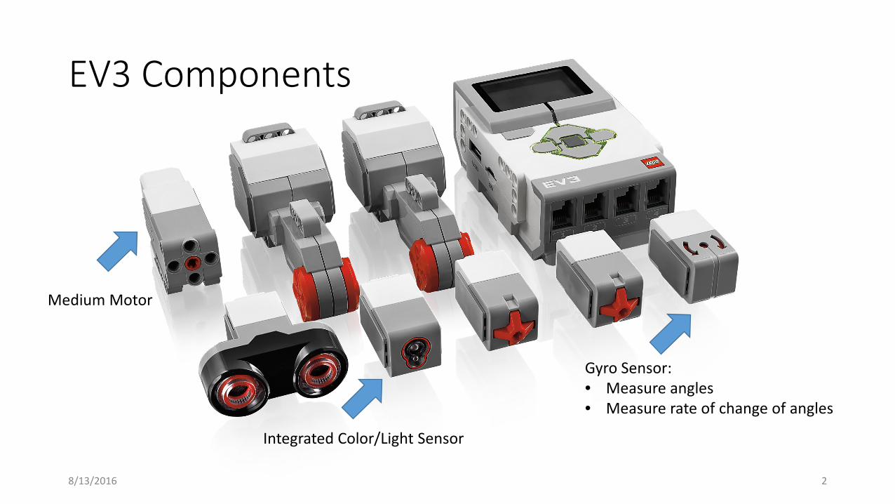
EV3 Components
Medium Motor
Integrated Color/Light Sensor
Gyro Sensor:• Measure angles• Measure rate of change of angles
8/13/2016 2
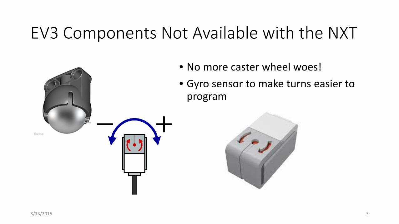
EV3 Components Not Available with the NXT
• No more caster wheel woes!• Gyro sensor to make turns easier to
program
8/13/2016 3
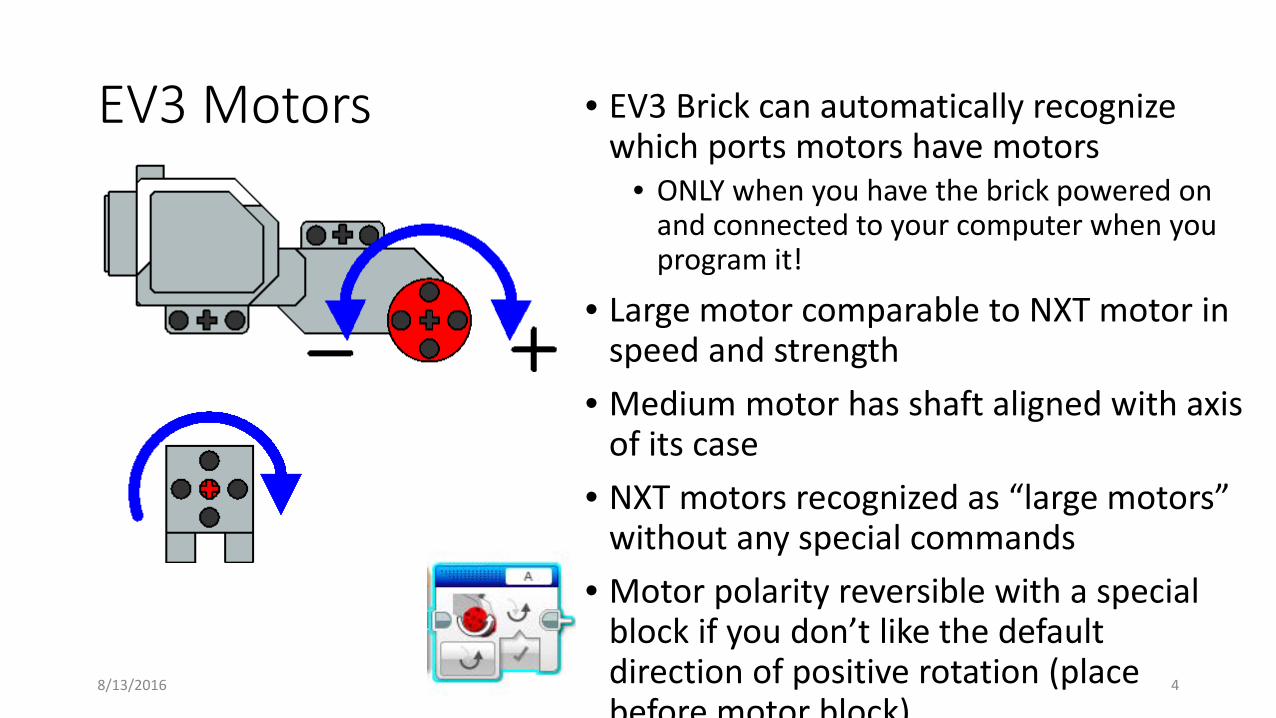
EV3 Motors • EV3 Brick can automatically recognize which ports motors have motors
• ONLY when you have the brick powered on and connected to your computer when you program it!
• Large motor comparable to NXT motor in speed and strength
• Medium motor has shaft aligned with axis of its case
• NXT motors recognized as “large motors” without any special commands
• Motor polarity reversible with a special block if you don’t like the default direction of positive rotation (place before motor block)
8/13/2016 4
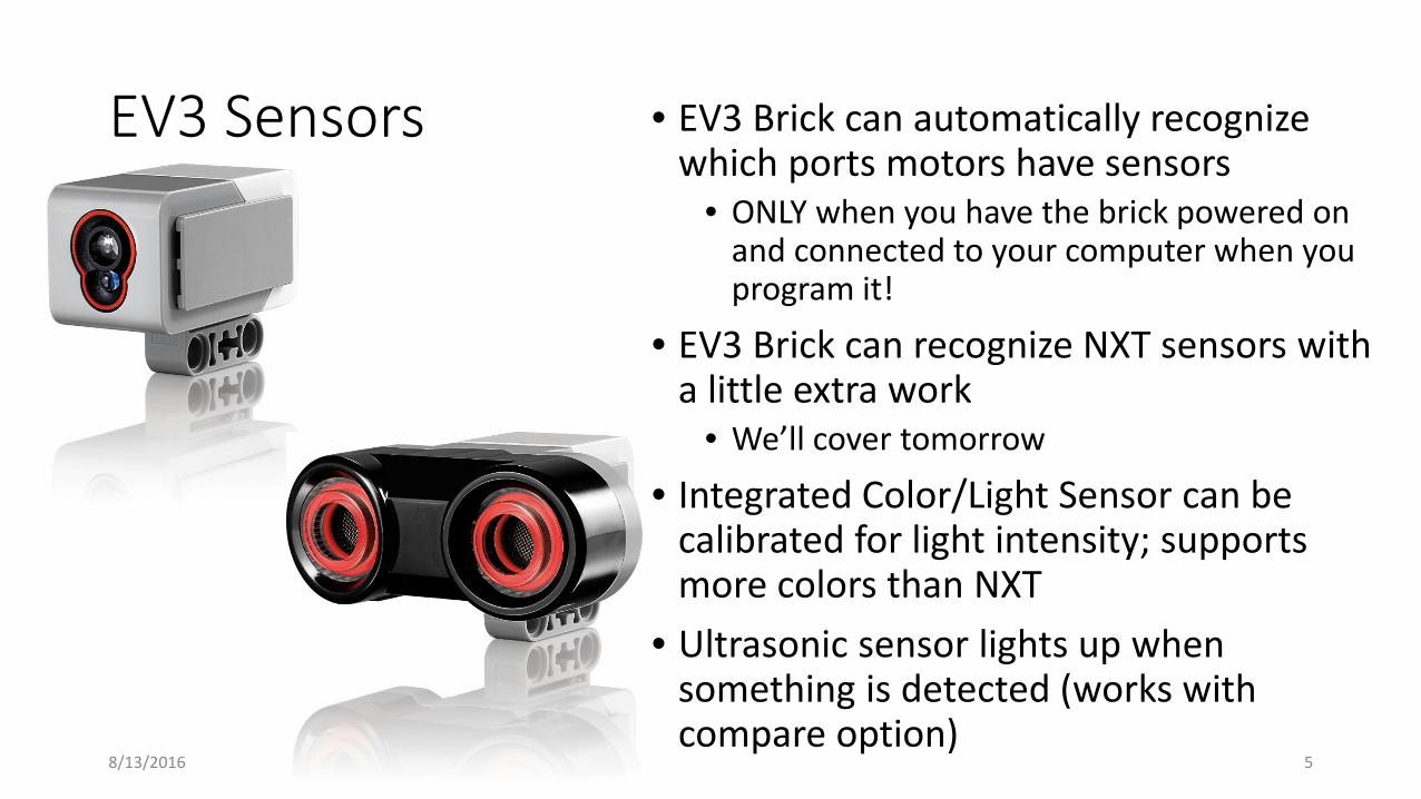
EV3 Sensors • EV3 Brick can automatically recognize which ports motors have sensors
• ONLY when you have the brick powered on and connected to your computer when you program it!
• EV3 Brick can recognize NXT sensors with a little extra work
• We’ll cover tomorrow
• Integrated Color/Light Sensor can be calibrated for light intensity; supports more colors than NXT
• Ultrasonic sensor lights up when something is detected (works with compare option)
8/13/2016 5
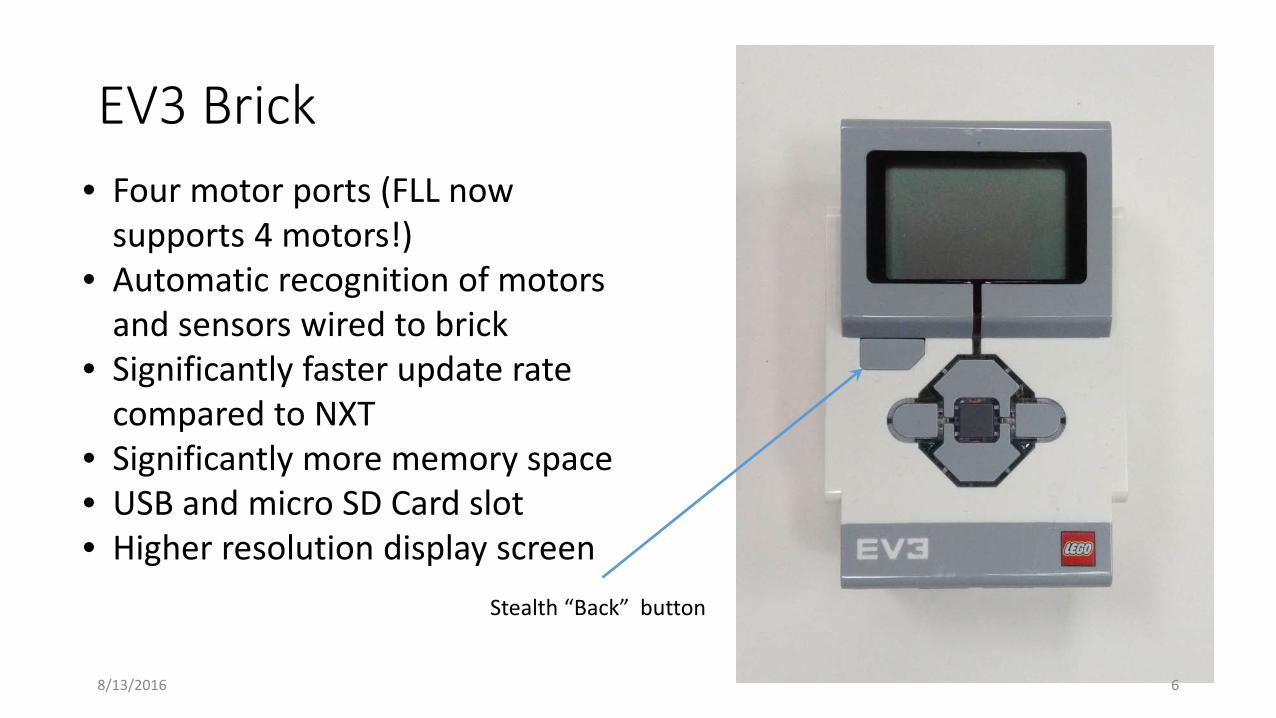
EV3 Brick• Four motor ports (FLL now
supports 4 motors!)• Automatic recognition of motors
and sensors wired to brick• Significantly faster update rate
compared to NXT• Significantly more memory space• USB and micro SD Card slot• Higher resolution display screen
Stealth “Back” button
8/13/2016 6

Improved Wire Tool
• Note shape of wire connectors – must be compatible to make connections• Can connect a number to a text port (no longer need “data to text” block)
8/13/2016 7
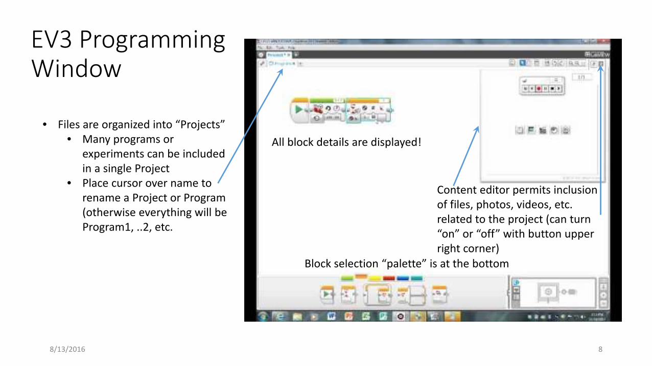
EV3 Programming Window
Block selection “palette” is at the bottom
• Files are organized into “Projects”• Many programs or
experiments can be included in a single Project
• Place cursor over name to rename a Project or Program (otherwise everything will be Program1, ..2, etc.
Content editor permits inclusion of files, photos, videos, etc. related to the project (can turn “on” or “off” with button upper right corner)
All block details are displayed!
8/13/2016 8
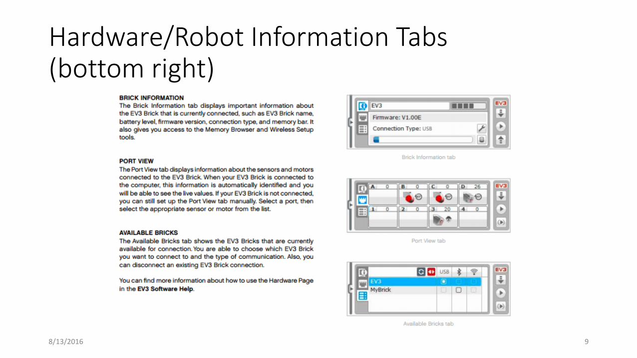
Hardware/Robot Information Tabs(bottom right)
8/13/2016 9
10
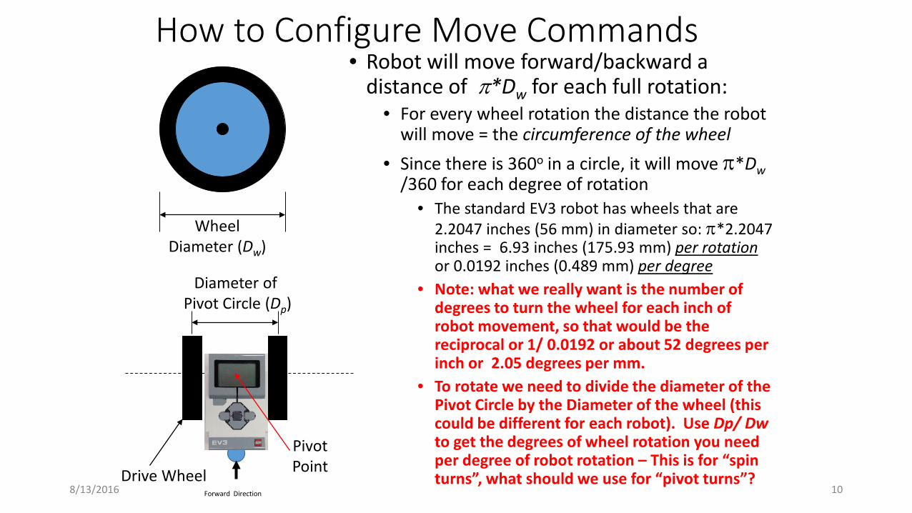
How to Configure Move Commands• Robot will move forward/backward a
distance of π*Dw for each full rotation:• For every wheel rotation the distance the robot
will move = the circumference of the wheel• Since there is 360o in a circle, it will move π*Dw
/360 for each degree of rotation• The standard EV3 robot has wheels that are
2.2047 inches (56 mm) in diameter so: π*2.2047 inches = 6.93 inches (175.93 mm) per rotation or 0.0192 inches (0.489 mm) per degree
• Note: what we really want is the number of degrees to turn the wheel for each inch of robot movement, so that would be the reciprocal or 1/ 0.0192 or about 52 degrees per inch or 2.05 degrees per mm.
• To rotate we need to divide the diameter of the Pivot Circle by the Diameter of the wheel (this could be different for each robot). Use Dp/ Dwto get the degrees of wheel rotation you need per degree of robot rotation – This is for “spin turns”, what should we use for “pivot turns”?
WheelDiameter (Dw)
PivotPoint
Diameter of Pivot Circle (Dp)
Forward Direction
Drive Wheel8/13/2016
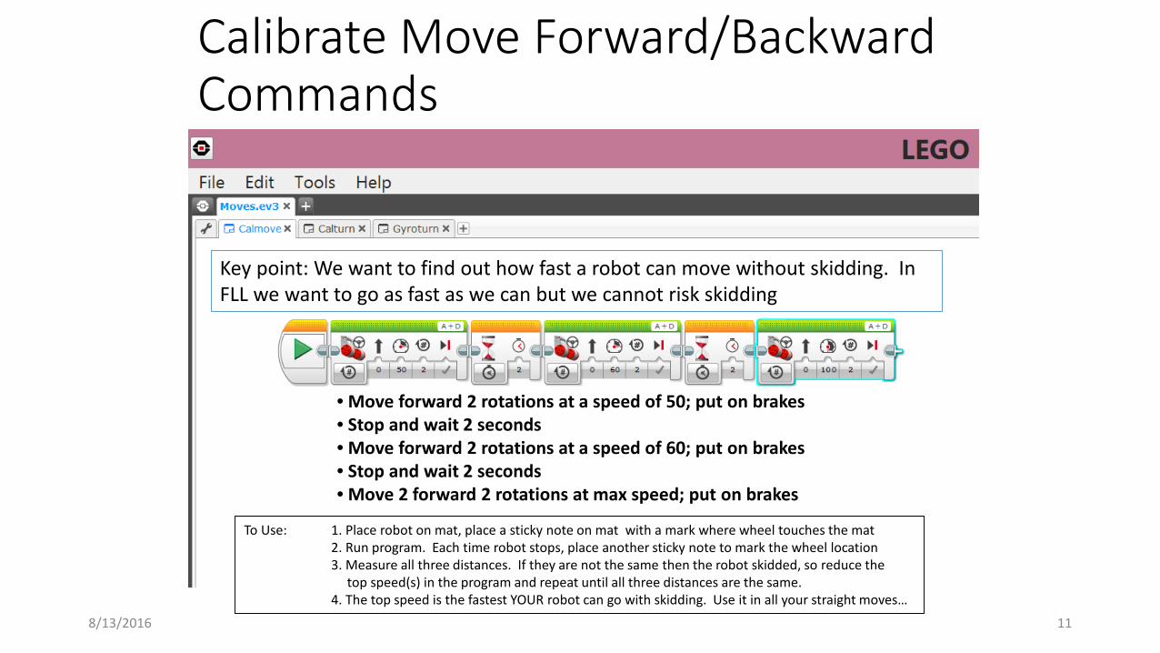
Calibrate Move Forward/Backward Commands
8/13/2016 11
• Move forward 2 rotations at a speed of 50; put on brakes• Stop and wait 2 seconds• Move forward 2 rotations at a speed of 60; put on brakes• Stop and wait 2 seconds• Move 2 forward 2 rotations at max speed; put on brakes
To Use: 1. Place robot on mat, place a sticky note on mat with a mark where wheel touches the mat2. Run program. Each time robot stops, place another sticky note to mark the wheel location3. Measure all three distances. If they are not the same then the robot skidded, so reduce the
top speed(s) in the program and repeat until all three distances are the same. 4. The top speed is the fastest YOUR robot can go with skidding. Use it in all your straight moves…
Key point: We want to find out how fast a robot can move without skidding. In FLL we want to go as fast as we can but we cannot risk skidding
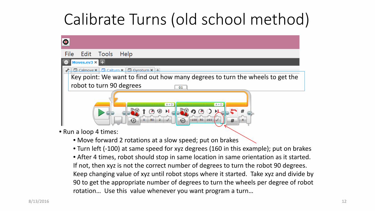
Calibrate Turns (old school method)
8/13/2016 12
• Run a loop 4 times:• Move forward 2 rotations at a slow speed; put on brakes• Turn left (-100) at same speed for xyz degrees (160 in this example); put on brakes• After 4 times, robot should stop in same location in same orientation as it started. If not, then xyz is not the correct number of degrees to turn the robot 90 degrees. Keep changing value of xyz until robot stops where it started. Take xyz and divide by 90 to get the appropriate number of degrees to turn the wheels per degree of robot rotation… Use this value whenever you want program a turn…
Key point: We want to find out how many degrees to turn the wheels to get the robot to turn 90 degrees
How does this relate to FLL?• Robots must start in “base”
• Students may touch the robot while in the base area without penalty
• Base is a volume
• Robots leave base area to collect items, place or shot items into scoring positions, or move scoring pieces on the board
• FLL approaches:• Use wheel encoders to keep track of how far the
robot has moved and what direction it is facing• Requires precise alignment in base area (students can fashion alignment fixtures
or “jigs” to start their robots with precision; must fit into Base)• Use sensors to locate the robot precisely at strategic locations and
move from there
8/13/2016 13
Robot Design Tips• Make sure the robot is balanced
• About 60% of its weight is on the drive wheels/40% on the caster ball (exact split is not critical – make sure the wheel traction is good and the caster ball is not carrying a lot of the robot weight)
• Make sure the robot doesn’t tip when moving to score (picking up something etc.)
• Keep the robot as compact as practical• A big robot is difficult to navigate around the field
• Make your robot a big as is practical to score and no bigger• A tall robot may not clear some of the field mission models
(different year to year)• Try to minimize the number of scoring fixtures required to be
attached/removed during a match• Complex fittings are impractical even if they score reliably
8/13/2016 14
Strategy• Strategic planning is critical – get everyone involved in
planning• Don’t let students charge off to build a robot for the first
mission they see… leads to dead ends and loss of enthusiasm.• Have the team review each mission and rank them in terms of
difficulty • What does the robot have to do to score
• How complex do scoring fixtures need to be; how specialized• How hard is it reach the scoring area; does the robot have to return to base
with something to score?• How many points is a mission worth? (rank risk/reward)• Start simple and move up… Better to do a few missions well than attempt many
missions with low probability of success
• Which missions can be combined into a single program? • Group missions by geographic location: If you are going to have
your robot travel far, make it worthwhile…8/13/2016 15
Mission Design Tips (1 of 3)
8/13/2016 16
• Combine as many missions as possible into each program • Match duration is too short to keep moving back to base• It takes too long to compose 17 or so programs!
• Minimize the number of starting positions in base • Try to use one starting position for all missions if possible (easier for students
to remember – they won’t get confused by the stress of the match)• Use sensors as much as possible given your team’s level of experience to
locate the robot out on the playing field• Light/color sensor for line following location detection• Touch sensor for wall contact
• Walls are Not a precise way to locate the robot except for direction
• Sonar sensor may be useful to achieve a stand-off distance from the wall or from a mission model (if it is large enough to be sensed)
Mission Design Tips (2 of 3)
8/13/2016 17
• When navigating from A to B apply the brakes after every Move command
• When using the robot to push something or move something, it is often best to let the robot coast after the last Move command to let its momentum carry it into position (so don’t use brakes when you wan the robot to crash into something)
• Use the field elements as much as possible to guide the robot
• Use sensors…
Mission Design Tips (3 of 3)
8/13/2016 18
• Never use Time as a measure of robot movement when navigating
• Results are too sensitive to battery charge!• Use degrees or Rotations (robot will move slowly with a low
battery but will still arrive at pretty much the same location)
• Almost always use time to measure movement of a scoring fixture
• When not under load, the results are not extremely sensitive to battery charge (picking something up would constitute a load; not wise to use time if doing that)
• If degrees or rotations are used and the robot cannot achieve the specified movement, the robot will cease to operate (blocks are executed in series and you can’t start the next one until you’ve finished the current one… Time always elapses, so you are guaranteed to carry on if you use time as your ending criterion and not degrees or rotations)
How to layout a Mission -• What you need:
• Ruler, protractor, and some post-it type stickers
• Start with robot in base where you can place it with precision
• Plan a series of points that the robot will travel to, then turn and proceed until it reaches the point where it can score…
• Mark of where the wheels will be at each point with post-it stickers
• Measure distances, angles and directions of turns
• Transcribe into Move commands…
8/13/2016 19

Step 1
8/13/2016 20
• Place robot on field in base• mark where wheels contact mat with post-it stickers on both sides• Starting point is the red dot in between the stickers…
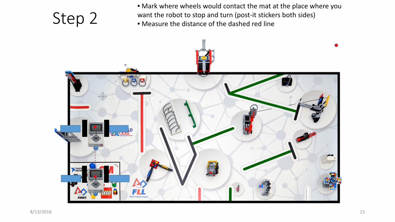
Step 2
8/13/2016 21
• Mark where wheels would contact the mat at the place where you want the robot to stop and turn (post-it stickers both sides)• Measure the distance of the dashed red line
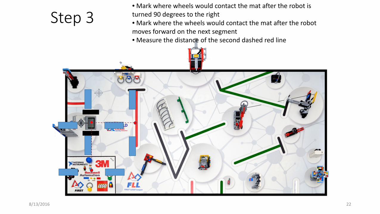
Step 3
8/13/2016 22
• Mark where wheels would contact the mat after the robot is turned 90 degrees to the right• Mark where the wheels would contact the mat after the robot moves forward on the next segment• Measure the distance of the second dashed red line
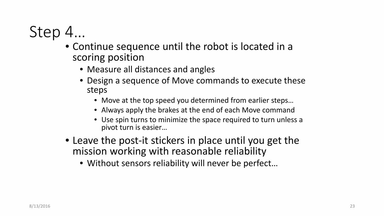
Step 4…• Continue sequence until the robot is located in a
scoring position• Measure all distances and angles• Design a sequence of Move commands to execute these
steps• Move at the top speed you determined from earlier steps…• Always apply the brakes at the end of each Move command• Use spin turns to minimize the space required to turn unless a
pivot turn is easier…
• Leave the post-it stickers in place until you get the mission working with reasonable reliability
• Without sensors reliability will never be perfect…
8/13/2016 23
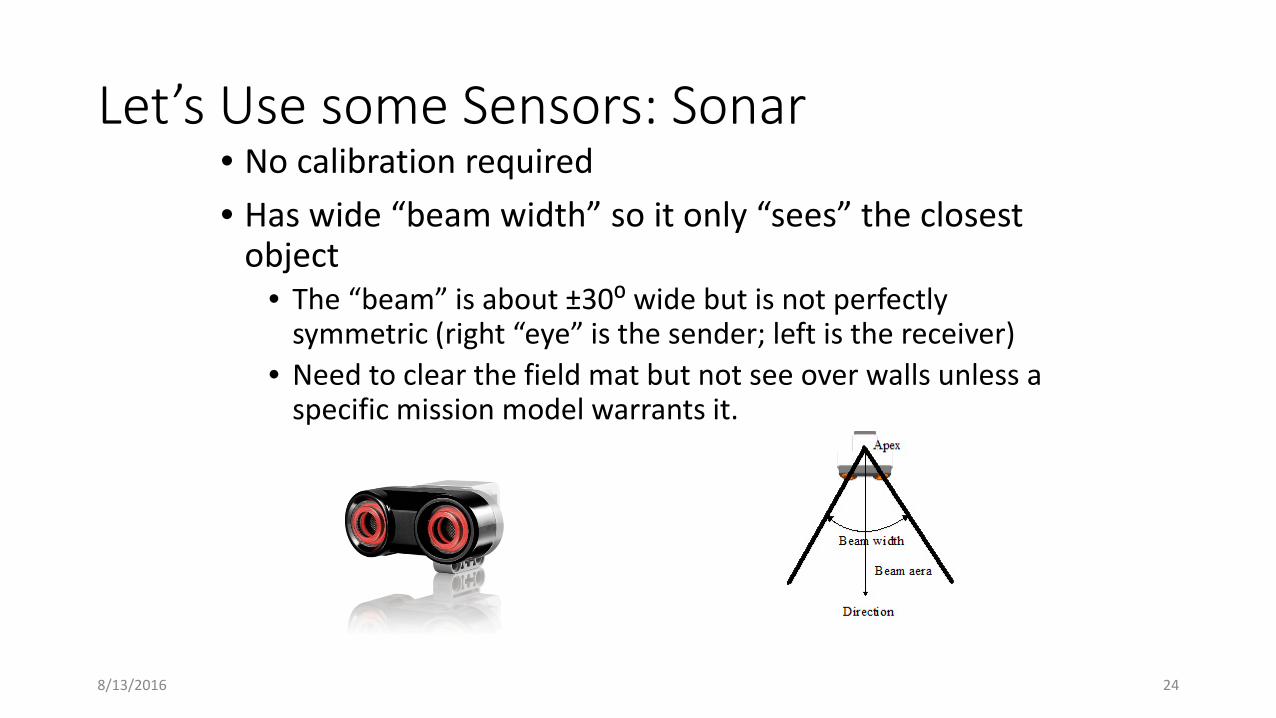
Let’s Use some Sensors: Sonar• No calibration required• Has wide “beam width” so it only “sees” the closest
object• The “beam” is about ±30⁰ wide but is not perfectly
symmetric (right “eye” is the sender; left is the receiver)• Need to clear the field mat but not see over walls unless a
specific mission model warrants it.
8/13/2016 24

Let’s Use some Sensors: Touch• No calibration required• Robot needs to bump into its environment
• Add a fixture to the sensor to get the desired bump distance if using on field
• Can be used to control program flow (drive forward until the robot hits a wall, then do something else…)
8/13/2016 25