Embed Size (px)
Citation preview

1
JSAEFormula SAE Japan
EV WG
EV Inspection Guide2019 Formula SAE Japan (FSAEJ)
Ver.20190322: Rev. page 3

2019 EV Inspection GuideContents1. Revisions to 2018 FSAE Rules for 2019 FSAE Rules
• Changes to be noted are listed.Check the FSAE website for the original details.
2. Key Points of EV Inspection: The usual mistakes will be explained.
• EV inspection procedure• *Inspection Sheet (Electric) 1 and 2 (Self-Check)• EV0: Basic electrical systems inspections• EV1: Inspections with high-voltage system OFF• EV2: Inspections with high-voltage system ON• EV3: Rain test
*Inspection Sheet (Electric) will be released on the team page.
3. Key Points of ESF and FMEA: Charging Procedure
4. Others 2

1. Revisions of 2019 FSAE Rules
• EV.1.4.7, 1.4.8: Violations during dynamic events• EV.3.2.4: All strong power connectors have been changed to those with
interlocks.• EV.3.3.3: Contactors and switches can no longer be used as
maintenance plugs.• EV.4.1.7, etc.: High-voltage display stickers• EV.4.3.6: Accumulator attachments• EV.5.1.8: The number of cells to measure the temperature has been
changed to 20% or more of the total number of cells.• EV.6.4.2, 6.4.6: The plug color has been changed to red for TSMPs and black
for GLVMPs.• EV.7.3.3: An orange circle with a diameter of 50 is required in the middle
of the TSMS.• EV.7.6.1: Open/short detection circuit has been added to the BSPD
circuit.
Changes to be noted are listed below.Confirm the changes carefully and take actions acco rdingly.
3

1. 2019FSAEJ Local Rules
J2019-19 Scatter Shield (refer to Formula SAE® Rules 2019 EV.2.1.4 )A gap between the hole of the motor casing and the scatter shield is allowed. As for the hole on a vertical surface to the rotation axis, the scatter shield is unnecessary.
J2019-20 Thickness of the floor or bottom for Accum ulator Container (refer to Formula SAE® Rules 2019 EV.4.2.2 a)An aluminum sheet thickness of 3.2 mm (0.125 inches) must be accepted up to a negative tolerance of 10%.
J2019-21 Accumulator Attachment – Interpretation of Corner Attachments (refer to Formula SAE® Rules 2019 EV.4.3.6 b.)The phrase “the corner of the segment” in the Formula SAE® Rules 2019 may also be interpreted as “the corner of the container”.
J2019-22 Relaxation of Rule Relating to Placement o f Temperature Sensor at Cell Negative Terminal (refer to Formula SAE® Rules 2019 EV.5.1.4)If the team uses a ready-made accumulator consisting of assembled cells (segments) that cannot be disassembled, the temperatures of the positive and negative terminals of the segments, and actual measured data from the measurement points of the temperature sensor installed inside the segment (time series data when charged at maximum current) must be clearly stated on the Electrical Systems Form (ESF). If rule EV.5.1.3 is satisfied by control using these temperature sensor values in its ESF, the team must not be required to satisfy rule EV.5.1.4.
4

1. 2019FSAEJ Local Rules
J2019-23 Ready-To-Drive-Sound (refer to Formula SA E® Rules 2019 EV.6.11.4〜EV.6.11.6)The car doesn’t have to make a Ready-To-Drive-Sound.
J2019-24 Relaxation of Requirement for Electrical C onnections to Use Positive Locking Mechanisms (refer to Formula SAE® Rules 2019 EV.6.5 .12〜EV.6.5.14)The requirement to use positive locking mechanisms described in EV.6.5.12〜EV.6.5.14 must be regarded as satisfied if the following conditions are all met.Conditions:- The team can clearly demonstrate that the reasonable axial force or contact pressure has been applied to the connections during the Electrical Technical inspection. (A record of the fastening torque or riveting bonding force is acceptable.)- Furthermore, the structure must allow no application of external force (tension, torsional, or flexural) from the wiring to the connection.
J2019-25 Method of Driving the Tractive Systems Acti ve Light (TSAL) via High-Voltage (refer to Formula SAE® Rules 2019 EV.6.10.1)To ensure that the TSAL flashes during Accumulator Isolation Relay (AIR) welding even when the Grounded Low Voltage Master Switch (GLVMS) is OFF, the power supply of the TSAL (red) must be taken from the tractive systems (TS) (e.g., via the DC/DC converter or the like) to drive the TSAL. The power supply of the TSAL (red) must NOT be taken from the Grounded Low Voltage (GLV).
5

1. 2019FSAEJ Local Rules
J2019-26 Flashing Requirements of TSAL (Green) (refe r to Formula SAE® Rules 2019 EV.6.10.4)Rule EV.6.10.4 must NOT apply to the lighting green light.
J2019-27 Relaxation of Prohibition of Cell Balancin g when Accumulator Isolation Relays (AIR) Are Open (refer to Formula SAE® Rules 2019 EV.7.2.5)This rule may be regarded as not applicable providing that the high voltage (HV) portions of the accumulator management system (AMS) are inside the accumulator container.
J2019-28 Coloring of Shutdown Buttons (refer to For mula SAE® Rules 2019 EV.7.4)EV shutdown buttons must be colored red. Other than the cockpit mounted shutdown button, switches installed at the driver’s seat must not be colored red or orange.
6

1. 2019FSAEJ Local Rules
J2019-29 Relaxation of Rules for EV Chargers (refer to Formula SAE® Rules 2019 EV.9.3)Teams may be exempted from complying with the three rules described below if all of the following conditions are satisfied: The documents of 'Standard Charging Procedure' and 'Charging Abnormality Procedure' must be submitted at the same time as the Electrical System Form, team members must be fully trained in the application of these two documents to charging operations, these team members must constantly monitor the state of charging while in possession of these documents, and these team members must be capable of taking the appropriate measures if an abnormality occurs during charging.(1) The interlock function related to the connection state of connectors described in EV.9.3.4
(However, the method used to confirm the connection state of the charger and accumulator must be clearly stated in the Standard Charging Procedure document.)
(2)The function to turn off the charger using the AMS described in EV.9.3.6(However, it must be possible to visually confirm the detection state of the AMS at all times. In addition, the abnormality types of AMS, judgment methods, and charging stop methods must be listed in the Charging Abnormality Procedure document.)
(3)The function to turn off the charger using the IMD described in EV.9.3.7(However, it must be possible to visually confirm the detection state of the IMD at all times. In addition, the abnormality types of IMD, judgment methods, and charging stop methods must be listed in the Charging Abnormality Procedure document.)
7
1. 2019FSAEJ Local Rules
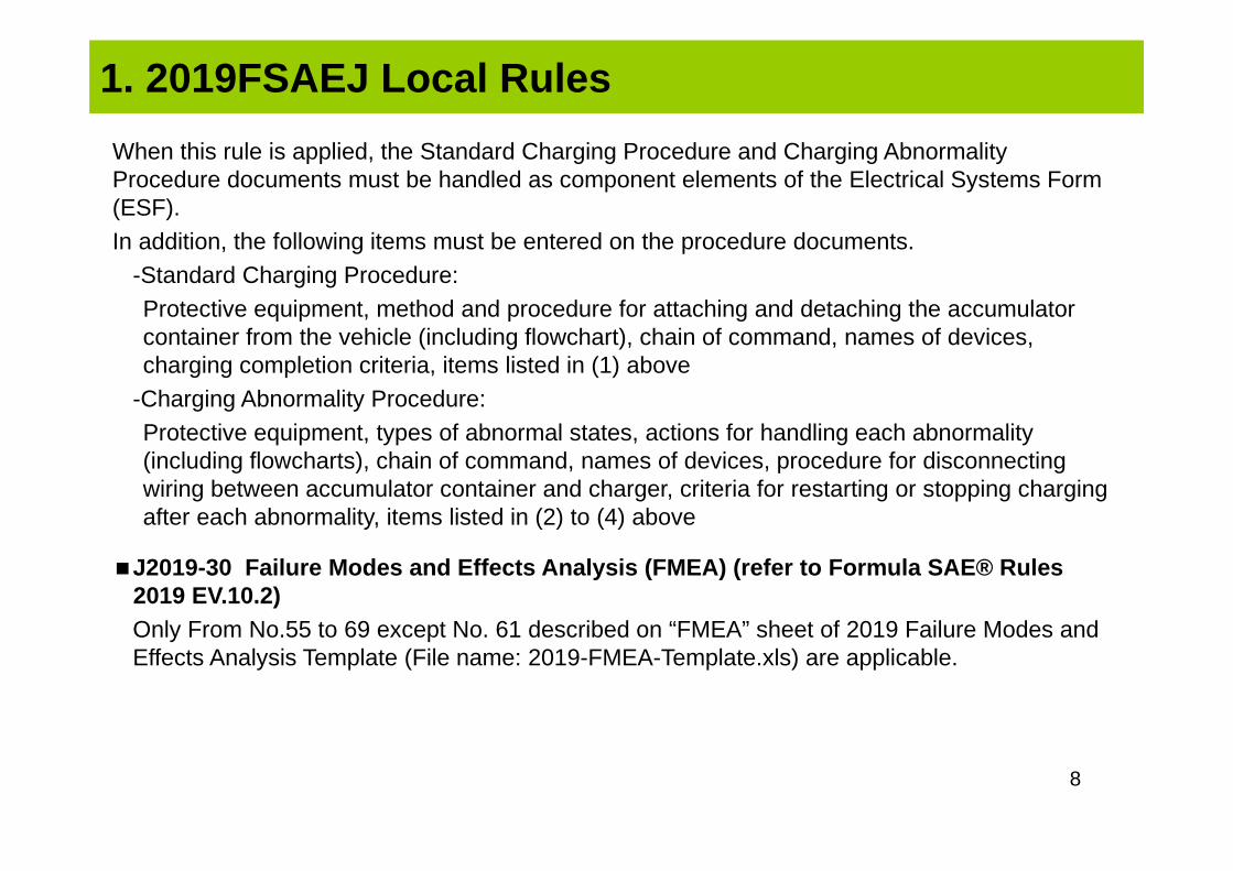
When this rule is applied, the Standard Charging Procedure and Charging Abnormality Procedure documents must be handled as component elements of the Electrical Systems Form (ESF).In addition, the following items must be entered on the procedure documents.
-Standard Charging Procedure:Protective equipment, method and procedure for attaching and detaching the accumulator container from the vehicle (including flowchart), chain of command, names of devices, charging completion criteria, items listed in (1) above
-Charging Abnormality Procedure:Protective equipment, types of abnormal states, actions for handling each abnormality (including flowcharts), chain of command, names of devices, procedure for disconnecting wiring between accumulator container and charger, criteria for restarting or stopping charging after each abnormality, items listed in (2) to (4) above
J2019-30 Failure Modes and Effects Analysis (FMEA) (refer to Formula SAE® Rules 2019 EV.10.2)Only From No.55 to 69 except No. 61 described on “FMEA” sheet of 2019 Failure Modes and Effects Analysis Template (File name: 2019-FMEA-Template.xls) are applicable.
8

1. 2019FSAEJ Local Rules
J2019-31 Submission of the ESF or FMEA (refer to Fo rmula SAE® Rules 2019 EV.10.3, FSAEJ2019 Participation Rules Article 12)Re-submission of the Electrical System Form (ESF) or Failure Modes and Effects Analysis (FMEA) may be requested multiple times to ensure that these materials achieve a sufficient degree of completion. In the event that re-submission is required, a maximum of fifty (50) negative points will be penalized depending on the degree of completion of these materials at the final deadline. However, the combined penalty due to the degree of completion and due to the late submission defined in rule EV.10.3 must not exceed fifty (50) negative points in total. In addition, the order of the Electrical Technical Inspection must be determined based on the degree of completion of the ESF and FMEA, as well as the order in which the documentation is received.
9
Referring to: FSAEJ Websitehttp://www.jsae.or.jp/formula/en/about.php#rules

2. Key Points of Electrical Technical Inspection: P rocedure
Technical Inspection
Tilt/Weight
Signing up EV0 EV1 EV2EV3
(Rain)
Brake
EV1:• Confirmation of circuit
configuration (inactive, high voltage OFF)Make proper preparation to explain these items.
EV2:• Confirmation of circuit
operation (active, high voltage ON)
Note the order of priority such as Technical Inspection sequence.
EV0:• Basic systems
Insulation stateRequirement for Mechanical Technical Inspection
• Confirmation of operationThe grounded low voltage (GLV) battery must be sufficiently charged.
• Rain testTeams should apply rain countermeasures assuming that the car will actually be driven in the rain.
• Refer to the Handbook for the location where the Technical Inspection Sticker is distributed and where the Technical Inspection Sheets are collected.
When the weather is fine, EV3 and the Brake Test may be carried out in any order.
The EV1 and EV2 set, and Mechanical Technical Inspection and Tilt/Weight Test set may be carried out in any order.
Revisions from 2018 Rules (Plan)
10
* Pass the Mechanical Technical Inspection and Tilt/Weight Test once at any of the timings below.
• The Energy Meter (EM) is distributed generally when the team has passed EV1.Refer to the Handbook for details.
• Teams should prepare a busbar or the like that is conductive without the EM.• EM installation
Teams must prepare the high-voltage terminals (round terminals).Other connectors will be provided by the JSAE.
Bring the removed cowling and other parts.

2. Key Points of Electrical Technical Inspection
• Fill out this sheet before the EV Inspection.It may not be filled out at the Inspection Area at that time.
• The purpose of this sheet is to confirm whether the overall high-voltage system is consistent (voltages, currents, etc.).
• Most of this sheet can be copied from the ESF.
Self-check of the overall system
Using the Inspection Sheet (Electric)
11

2. Key Points of Electrical Technical Inspection
• Create the accumulator container following the design guidelines of EV.4.2.2 since the standard accumulator container is not defined.
• Please bring drawings and photographs if the configuration is difficult to see at the Technical Inspection Area.→ If these are not prepared, teams may be asked to dismantle the container.
Self-check of accumulator container
12

Review: Accumulator Container
EV.4.2.2 Item Outline
Materials
a Floor or bottom Steel: 1.25 mm (0.049 inch) / Aluminum: 3.2 mm (0.125 inch)
b External vertical walls Steel: 0.9 mm (0.035 inch) / Aluminum: 2.3 mm (0.09 inch)
c Internal vertical walls Steel: 0.9 mm (0.035 inch) / Aluminum: 2.3 mm (0.09 inch)Must be minimum of 75% of the height of the external vertical walls
d Covers and lids Steel: 0.9 mm (0.035 inch) / Aluminum: 2.3 mm (0.09 inch)
e Joining method of floor and walls Welds and/or fasteners: Fasteners must be 6 mm Metric Grade 8.8 or stronger.
Joining
f
Weight in each section The accumulator container must be divided into sections by vertical walls. A maximum of 12 kg is allowed in any section.
Number of fasteners between floor and any vertical wall (internal or external) At least 2
Fasteners between internal and external vertical walls Must be located in the top half of the internal vertical wall
Number of fasteners for each section Sections containing 8 kg or less: minimum of 2 fasteners connecting any two vertical walls
Number of fasteners for each section Sections containing between 8 and 12 kg: minimum of 3 fasteners connecting any two vertical walls
g Plate folding or bending The folding or bending of plates to create flanges or eliminate joints between walls is acceptable.
h Location of cover or lid fasteners Covers or lids must be fastened with a minimum of one fastener for each external vertical wall per section.
i Alternate materialsAlternate materials are allowed with proof of equivalency following rule T.3.31. Proof of
equivalency must be documented in the Structural Equivalency Spreadsheet (SES) and test samples must be available at the Technical Inspection.
j Use of smaller bolts One 6 mm bolt may be substituted with two 5 mm or three 4 mm bolts.
Assumptions of guidelinesLongitudinal: 40GLateral: 40GVertical: 20G
EV.4.2.2: Configuration of accumulator container
13
The guidelines of EV.4.2.2 is not applicable if iron or aluminum materials are not used (such as CFRP).

EV.4.2.3: Securing of cells and/or segments inside the container• The cells and segments must not move in the container with a load of 40G in
the longitudinal (front/rear) direction, 40G in the lateral (left/right) direction, and 20G in the vertical (up/down) direction.
• Calculations and/or test results must be included in the SES.• The fastener must have a strength of 6 mm Metric Grade 8.8 bolt (1/4 inch
Metric Grade 5 bolt in the SAE standard) or more. (Refer to T.10.2 and T.10.3.) (The example of fasteners are listed on the next page.)
EV.4.3.5/4.3.6/4.3.7: Attachment of container to major structureThe design must follow one of the two rules listed below.
• EV.4.3.6: Corner Attachments and Analysis• EV.4.3.7: Load Based Analysis of the Accumulator Container
Review: Accumulator Container
14
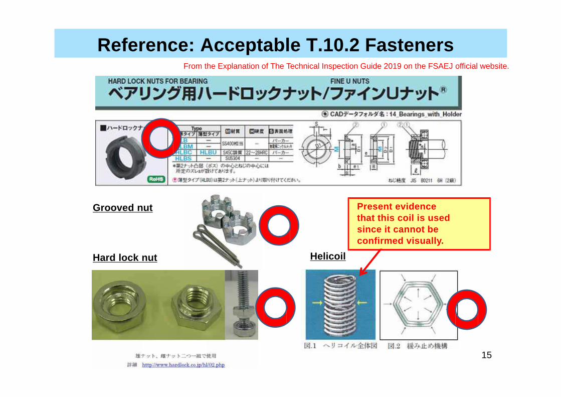
Grooved nut
Hard lock nut Helicoil
Present evidence that this coil is used since it cannot be confirmed visually.
Reference: Acceptable T.10.2 FastenersFrom the Explanation of The Technical Inspection Guide 2019 on the FSAEJ official website.
15

Judgment will be made based on the following fasten er requirements.a. The device system can be confirmed visually.b. Positive locking mechanisms do not rely on the clamp force for locking.c. The nut and bolt will not become completely loose even if they have become loosened a little.
U nut
Super slit nut
Wedge lock nut
Muscle nut
Present evidence for parts that cannot be determined from the outside.
16
Reference: Acceptable T.10.2 FastenersFrom the Explanation of the 2019 Mechanical Technical Inspection Rules
2. Key Points of Electrical Technical Inspection
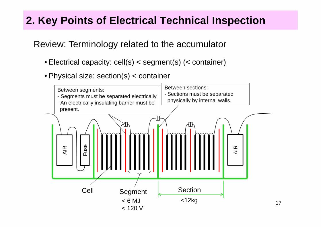
• Electrical capacity: cell(s) < segment(s) (< container)
• Physical size: section(s) < container
Review: Terminology related to the accumulator
Fus
e
AIR
AIR
Cell Segment Section
Between segments:- Segments must be separated electrically.- An electrically insulating barrier must be present.
< 6 MJ< 120 V
Between sections:- Sections must be separated physically by internal walls.
<12kg 17

2. Key Points of Electrical Technical Inspection
Shutdown buttons:• Two shutdown buttons must be located behind the driver's compartment at
approximately head height, one at each side of the car. The diameter of the buttons must be at least 40 mm.
• One shutdown button must be located around the steering wheel. The diameter must be at least 24 mm.
• A label consisting of "a red spark on a white-edged blue triangle" must be affixed close to all shutdown buttons.
Resistance measurement using Tractive System Measuring Points (TSMP)
• Before the Electrical Technical Inspection, teams must prepare to enable measurement using the TSMP (these measuring points are often set far back into the car).
• Wiring leading to the TSMP must be orange because high voltage is applied! (Caution is required.)
• The TSMP must be a red 4 mm shrouded banana jack.
EV0: Basic electrical systems inspectionTeams may take the Mechanical Technical Inspection after passing this inspection.
18

2. Key Points of Electrical Technical Inspection
GLVMP (GND measuring point)• This measuring point should be connected using a thick low-resistance
wire since it is used for measuring the contact resistance.
HVD• The "HVD" label should be attached to the back surface rather than the
side to make it easier to see from the rear.• The HVD must be mounted to the location specified in EV.6.2 Positioning
of Tractive System Parts and must not deviate from that position.• An untrained person must be able to remove the HVD within 10 seconds.
(Some teams even attach a diagram.)• It must be possible to disconnect the HVD without removing the cowling or
any bodywork.• Opening a lid or cover is acceptable. However, if the process is not intuitive,
it will be impossible to comply with the 10-second rule.• Open the AIRs when the HVD is removed.
19

Review: Display of lightning bolt/spark for high voltage
systemsEV.4.1.7 Accumulator
containerISO 7010-W012 (triangle with black lightning bolt on yellow background)
• Triangle side length of at least 100mm
• The text “Always Energized”
EV.6.6 TractiveSystemEnclosures
• The text “High Voltage”
EV.7.3.3 TractiveSystem MasterSwitch
• Be labeled “HV” or “TS”
EV.7.4.5EV.7.4.6
ShutdownButtons
The international electrical symbolconsisting of a red spark on a white-edged blue triangle
Review: Lightning bolt/spark
NG
20All the label texts must be in English. (Japanese is not acceptable.)

2. Key Points of Electrical Technical Inspection
Attachment condition of cables• Cables must not be fixed to each other. All cables must be fastened
securely to the body.• Cables should be wrapped in corrugated sheaths: Cables will break if
the cover is damaged. (This is a cause of grounding faults and electrical shocks.)
• All cables should be appropriately gathered together and fixed to the body (do not leave them in an untidy state): This is a cause of incorrect connections and other faults.
• Use different color wiring. If all the wires are the same color, it will be confusing when checking the wiring after an issue occurs.
Installation method of tractive system accumulators• It must be possible to remove the tractive system accumulator from the
car without disassembling the accumulator container.
EV1: Technical Inspections when high voltage system is OFF
21

2. Key Points of Electrical Technical Inspection
Confirmation of electrical safety of tractive system accumulator• Teams must prepare photographs of the state inside the accumulator
container. It is very difficult and time consuming to open the container during the Electrical Technical Inspection.
• Segments must be separated electrically without requiring the use of a tool. It is prohibited to use hand tightened nuts in the separation structure. Connectors and service plugs must be used.
Confirmation of wiring of the tractive system supply• All tractive system power must flow through the energy meter.
→ When accumulator containers are connected in parallel, the accumulator containers must be wired to a single point.
• Teams are strongly recommended to install their own energy meter.→ This meter can be used to collect data for analysis by each team.
Data measured by the energy meter distributed at the event will not be provided to teams.
→ This energy meter is also useful as a backup in case an issue occurs.
22

Reference: Details of energy meter connection
Each team should prepare the round high-voltage terminals.
These connectors will be provided by the JSAE.
This is for low-voltage use.
This is for positive voltage input on the high-voltage side.
23
Energy Meter Specification:https://tech.jsae.or.jp/formula/2019team/news/No.1_%E3%80%90For_EV_Only%E3%80%91Energy_Meter_Specification.pdf
EMs will be distributed to the EV teams on the day of the event. See the Team Handbook for details.
2. Key Points of Electrical Technical Inspection
Firewall• There must be an electrically insulating layer surrounding the driver on
the driver's side.• There must be no holes near the driver. Gaps of pass-throughs for wiring
must be sealed.• If a battery is located at the side, the insulation must cover the side of the
driver. The escape route must be secured.
Confirmation of contact safety of high-voltage system• All high-voltage terminals and the like must be isolated by covers and
gaps filled with silicon or the like. The inspectors will confirm whether contact is possible using a 6 mm diameter probe or finger.
Accumulator Management System (AMS) (Battery Management System (BMS))
• If a team purchases an accumulator (cells) that is integrated with an AMS or BMS, consider using it as-is (without making any changes).
• AMS wiring should be collected together tidily and not left in an untidy state. Ensure a clean arrangement by placing a board in the container or adopting another measure.
24

2. Key Points of Electrical Technical Inspection
Tractive system partsTractive system parts must be installed in locations designated in EV.6.2 Positioning of Tractive System Parts to protect the parts from rear and side collisions.Note: The main purpose is to protect high-voltage parts from direct damage if
a collision occurs.If the car clearly deviates from that purpose (for example, if rigid components that accompany these parts protrude from the above position), this will be pointed out during the Technical Inspection.
E.g. 1: When the motor is within the above position, but the transmission (i.e., a robust rigid component coupled with the motor) protrudes from the above position.
E.g. 2: When the accumulator container is within the above position, but its cooling fan (i.e., a rigid component that directly accompanies the accumulator container) protrudes from the above position.
25

2. Key Points of Electrical Technical Inspection
Confirmation of shutdown circuit• This will be confirmed using the ESF or the like.• Teams should print out and bring a large copy of the circuit diagram (A2 or
A3 size) that is easy to read. If the diagram is too small, it is hard to see.• Bring two types of diagrams: one that shows the overall configuration, and
one that shows individual areas.
26

EV.7.3 Master Switches
• No interlocks may be connected in the area in the diagram on the left.
• Only pre-charge circuitry and hardwired interlocks may be located in the area. (EV.7.3.3)
TSMS
AIR_P
AIR_N
Revision: Shutdown Circuit and Systems
Key points:
27

2. Key Points of Electrical Technical Inspection
Confirmation of Accelerator Pedal Position Sensors (APPS)• Two entirely separate sensors must be used as APPS. Both the power
wires and output wires must be independent and cannot be shared.• Each APPS must have a separate detachable connector. The dedicated
Technical Inspection switch box may also be used.• In a past APPS connector detaching test, a team was unable to stop the
motor, which resulted in abnormal high-speed rotation of the motor. In order to prevent such dangerous situations, teams must check in advance.
Accelerator pedal return springs• Each return spring must be capable of returning the pedal to the fully
released position when the other is not functional.• Weak springs inside the APPS are not acceptable.
Either two springs must be used that are recognizable when viewed from the outside, or the teams must explain the internal structure.
28

2. Key Points of Electrical Technical Inspection
Confirmation of contact state (electrical shock protection by potential equalization)
The inspectors will confirm whether the prescribed locations are connected to the chassis ground at or below the required resistance.• Locations that teams often forget:
- Steering wheel surface- Parts operated by the driver attached to plastic panels (switches, etc.)
• Smart teams directly connect ground wires and do not rely on bolt joints. Paint and the like often prevents conductance.
• When conductive parts such as CFRP, honeycomb core, and metal fiber are used within the prescribed areas (use of conductive parts has increased in recent years).Special measures are required to ensure a sufficiently low contact resistance with carbon parts.E.g.: Incorporating metal meshes into the carbon fiber, ensuring definite the
Grounding wire with the aluminum honeycomb (core) as the measurement point.
29

2. Key Points of Electrical Technical Inspection
Confirmation of start-up method• The easiest confirmation method is to use the "ready-to-drive mode" indicator.
Teams have designed cars in the past in which even the driver could not confirm "ready-to-drive mode"
Tractive System Active Light (TSAL)• If there is a high voltage between AIR and the inverter, we recommend turning
TSAL on the power supply between AIR and HVD.( To warn you when the accumulator output can not be shut down, such as AIR welding)
Confirmation of high-voltage system shutdown• When the GLV master switch is turned OFF, the voltage might not drop in
5 seconds. Teams should examine the relationship between the GLV master switch and the discharge circuit.
EV2: Finally, Technical Inspections when high voltage system is ON
30

2. Key Points of Electrical Technical Inspection
Confirmation of tractive system accumulator pack operation indication• When high voltage is present on the outer side of the AIR, the indicator must
operate even when the container is removed from the body.• An analog voltmeter is permitted.
Confirmation of safety when Brake System Encoder (BSE) error occurs• The brake sensor used for error detection must be used for the brake override
(EV.2.4).• It is strongly recommended that the same sensor as this be used for the brake
sensor in the Brake System Plausibility Device (BSPD, EV.7.6), which is the final measure against the car running out of control.
31

2. Key Points of Electrical Technical Inspection
Confirmation of BSPD operation• Each team must consider how to prove BSPD operation (the method may be
described on the ESF).• Confirmation by non-operation of the brake override is not the preferred
method.• Teams should assume that it will not be possible to confirm at the Technical
Inspection Area with the power of 5 kW or more actually delivered. A normal method is to use a pseudo signal that indicates 5 kW or more.
• A requirement to include the shutdown circuit when detecting a 5kW sensor, disconnection of the hard braking sensor, or short circuit is added from 2019. (EV.7.6.1.c)This should be made possible with a hard circuit (window comparator circuit etc.) without using the microcomputer.
Confirmation of Insulation Monitoring Device (IMD)• Cautions when using the IMD manufactured by Bender (supplied by Protrad):- Connect the two ground wires separately.- Teams should thoroughly discuss the addition of a voltage detection function
(when purchasing a new one).When this detection function activates, shutdown will take place before the high voltage builds up.
32

2. Key Points of Electrical Technical Inspection
Confirmation of operation of IMD• Teams must prepare the resistance (of at least 250 Ω/V) that triggers detection
and operation during the Technical Inspection.
Confirmation of chargerCautions regarding the Standard Charging Procedure and Charging Abnormality Procedure documents:• Both should be expressed as flow charts.• Use diagrams (photographs) to make them easier to understand.• Refer to the local rule J2019-29 Easing Charger Equipment for the indications required.
• Both procedures are handled as component elements of the ESF. If there are any items left blank or mistaken, the procedures need to be submitted again.
33

Key points:• The two reference ground wires of the IMD must be connected to the chassis
separately.• During the Technical Inspection, one or two of the reference ground wires will
be disconnected to check that a failure occurs.
IMD
Review: Insulation Monitoring Device (IMD)
Teams should test in advance whether a failure is detected under both of these conditions.
34

2. Key Points of Electrical Technical Inspection
• Each team should prepare a stand (above figure) that can hold the car with all four wheels approximately 50 to 150 mm above the ground.
• Seals will be attached to plastic covers and the like used as a countermeasure against rain. → These cannot be removed.→ Use a structure that does not use tape or the like to seal against rain.
• In the event of an emergency, teams should bring enough insulated gloves for the people required to lift the car up.
• This test can be failed in circumstances other than an insulation failure (electrical leakage) (e.g., sensor signal disruption leading to shutdown).
EV3: Rain Test
• After accelerating, the system must be stopped by pressing the shutdown buttonbefore braking.
• Since it is more difficult to lock the tires with an EV than a gasoline-powered car, the same design may not work.
→ This is caused by higher weight and the rotational inertia of the motor applied to the drive wheels.
Reference: Brake Test
35
50~
150
(a) body support type (b) body & arm support type
50~
150
keep the body horizontally

• Why can't you calm down?
Jacking up the car Rotating the motor Measuring potential Charging
Operations involving touching the components placed inside the accumulator container must be carried out in the Charging Area.
High-voltage wiring connection Wiring inside the accumulator container
CAEREFUL Operations in the EV Inspections
Although the following operations will not be carried out at the Inspection Area, Check the next pages just for your information.
The team members will be asked to perform various operations during the EV Inspections. Just chill out.
Accumulator container must be removed from the car for charging.

© Photograph by Shidhartha De at Formula Student Germany (FSG)
Safety in High -voltage wiring connection
Key point:Only the connection operation area is uncovered.
Key point:Short circuits caused by screws and the like can cause molten metal to jump out like fireworks.

© Photograph by Shidhartha De at Formula Student Germany (FSG)
Safety in Wiring inside the accumulator container
Key point:Cables move.Although troublesome to set up, covers can be beneficial.