Embed Size (px)
Citation preview
EUV Source Supplier Update, GigaphotonHakaru Mizoguchi
AcknowledgmentsA part of this work was performed under the A part of this work was performed under the
management of EUVA in the NEDO's R&D Program.management of EUVA in the NEDO's R&D Program.
EUV Source Workshop6 May, 2007
Baltimore, MD, USA

05.May 2007. P2
Introduction - LPP source roadmap and concept
Update of CO2 laser produced Sn plasma source - Laser output power- Sn deposition analysis- System scalability
LPP/EUV future direction to HVM
Summary
OutlineOutline

05.May 2007. P3
1st Mid term2004/9
2nd Mid term2006/3
EUVA Final2008/3
HVM source-12010
planning5.7W 1)
---YAG:1.5kW
10kHz0.9%
Xe-Jet
110W 2) /140W 3)
3s<±0.3%CO2: 10kW
100kHz4%
Sn-Droplet
10W 1)
s<±10%CO2:2.6kW
100kHz0.9%
SnO2 choroid liquid jet
EUV Power (IF)Stability
Laser Laser freq.CE (source)
Target
50W 2)
s <±5%CO2: 7.5kW
100kHz2.5%
Sn-Droplet
LPP Source Roadmap
Technology for <10WTechnology for <10WNd:YAG Laser, Liquid Xe jet
Technology for 115Technology for 115--200W200WCO2 Laser, Sn droplet target
Magnetic field mitigationNote)Primary source to IF EUV transfer efficiency:1) 43% 2) 28% with SPF3) 36% without SPF
EUVA project Gigaphoton
05.May 2007. P4
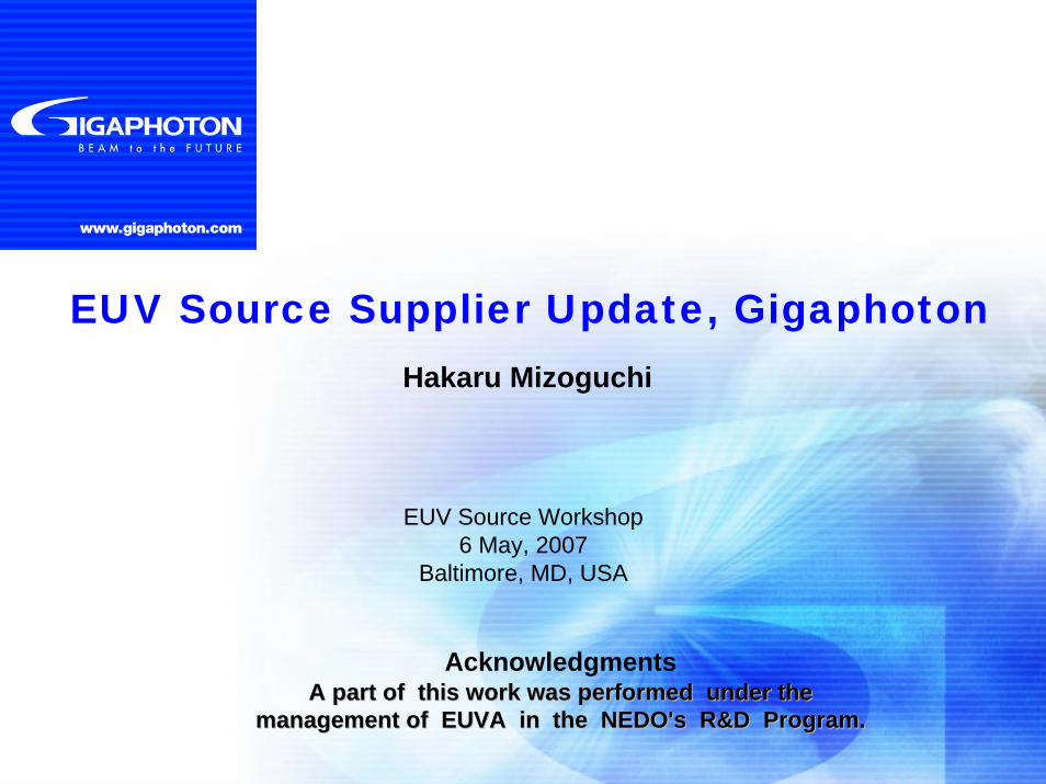
CO2 laser + Sn LPP light source+ Magnetic field mitigation
Sn target supply
Magnetic field mitigation
IF
High power pulsed CO2 laser system
Pulsed CO2 Laser OSC+cw-CO2 laser AMP
Light Source Concept
High EUV power >115 WEUV StabilityCollector mirror lifetime Low CoG / CoO
Requirement for EUV source for HVM
Original Concepts
05.May 2007. P5
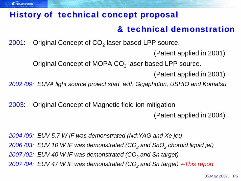
History of technical concept proposal History of technical concept proposal
& technical demonstratio& technical demonstrationn2001: Original Concept of CO2 laser based LPP source.
(Patent applied in 2001)Original Concept of MOPA CO2 laser based LPP source.
(Patent applied in 2001)2002 /09: EUVA light source project start with Gigaphoton, USHIO and Komatsu
2003: Original Concept of Magnetic field ion mitigation (Patent applied in 2004)
2004 /09: EUV 5.7 W IF was demonstrated (Nd:YAG and Xe jet)2006 /03: EUV 10 W IF was demonstrated (CO2 and SnO2 choroid liquid jet)2007 /02: EUV 40 W IF was demonstrated (CO2 and Sn target)2007 /04: EUV 47 W IF was demonstrated (CO2 and Sn target) ←This report
05.May 2007. P6
Introduction - LPP source roadmap and concept
Update of CO2 laser produced Sn plasma source - Laser output power- Sn deposition analysis- System scalability
LPP/EUV future direction to HVM
Summary
OutlineOutline
05.May 2007. P7
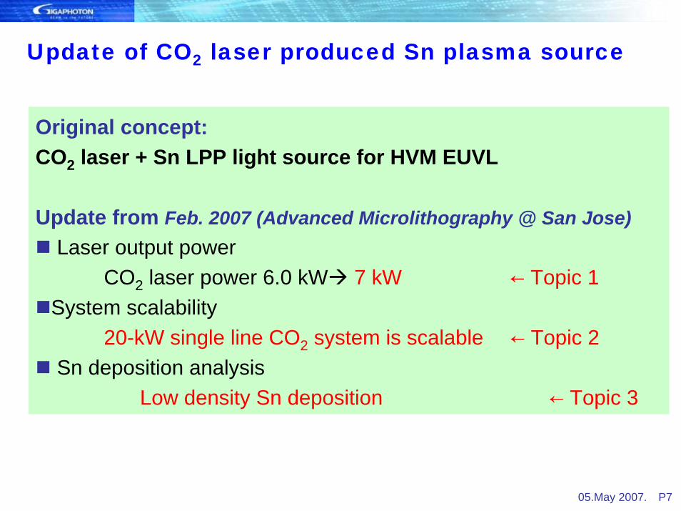
Update of CO2 laser produced Sn plasma source
Original concept:CO2 laser + Sn LPP light source for HVM EUVL
Update from Feb. 2007 (Advanced Microlithography @ San Jose)Laser output power
CO2 laser power 6.0 kW 7 kW ← Topic 1System scalability
20-kW single line CO2 system is scalable ← Topic 2Sn deposition analysis
Low density Sn deposition ← Topic 3

05.May 2007. P8
Experimental devices for EUV source development at EUVA
Target ChamberTarget Chamber1. High power experiment device
RF-CO2 laser based systemHigh power laser system developmentTarget developmentHigh power EUV generation
2. Fundamental experiment device
TEA-CO2 laser based systemCE experimentDebris analysisMitigation system development
Component development is drivenby two experimental devices.
05.May 2007. P9
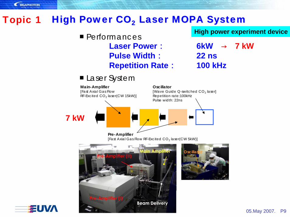
High Power COHigh Power CO22 Laser MOPA SystemLaser MOPA System
■ Laser SystemMain-Amplifier[Fast Axial Gas Flow RF-Excited CO2 laser(CW 15kW)]
Pre-Amplifier[Fast Axial Gas Flow RF-Excited CO2 laser(CW 5kW)]
Oscillator[Wave Guide Q-switched CO2 laser]Repetition rate:100kHzPulse width: 22ns
7 kW
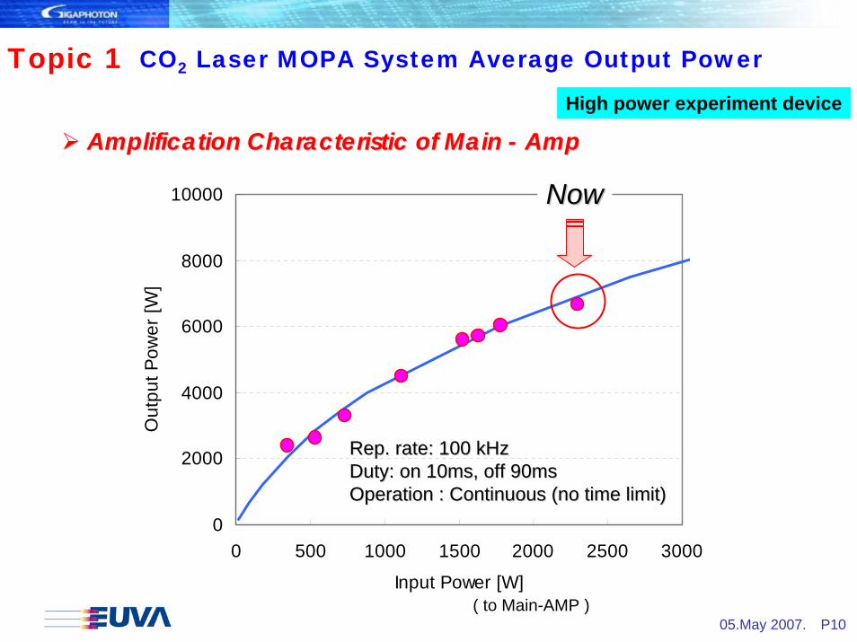
Laser Power: 6kW → 7 kWPulse Width: 22 nsRepetition Rate: 100 kHz
■ Performances
Oscillator
High power experiment deviceTopic 1
05.May 2007. P10
CO2 Laser MOPA System Average Output Power
Amplification Characteristic of Main Amplification Characteristic of Main -- AmpAmp
0
2000
4000
6000
8000
10000
0 500 1000 1500 2000 2500 3000
Input Power [W]
Out
put P
ower
[W]
( to Main-AMP )
Rep. rate: 100 kHzRep. rate: 100 kHzDuty: on 10ms, off 90msDuty: on 10ms, off 90msOperation : Continuous (no time limit)Operation : Continuous (no time limit)
NowNow
High power experiment device
Topic 1

05.May 2007. P11
EUV from high power CO2 laser produced Sn plasma
EUV source power : 110 W (130 W) (2 πsr, 2%bw)
Target : Rotating Sn plateLaser irradiation power: 5 kW (→ 6 kW)Conversion efficiency (CE): 2.2 %EUV energy stability : 8% (3σ, 50 pulse)
0
0.2
0.4
0.6
0.8
1
1.2
1.4
1.6
0 100 200 300 400 500 600 700 800
Number of pulses
EUV
ener
gy [m
J]
High power experiment device
Topic 1

05.May 2007. P12
0
20
40
60
80
100
2002 2003 2004 2005 2006 2007 2008Year
IF E
UV
pow
er (W
)
DPPLPP
DPP data based on EUVA / DPP, October 2006
LPP/ EUV Output Power
LPP IF EUV power caught up the 1st gen. Sn base-DPP power level !
Now
1st gen.
Sn base DPP
2nd gen.
Sn base DPP
High power experiment device
Transmittance from primary to I/FPrimary source EUV power (2pi sr, 2%bw) 616-702 W 110 W (130 W) Debris shield transmission 0.8 1.0 Collection angle & collector transmission 0.28 0.38 (4 sr, R=0.6) Aperture (etendue limit & SPF) transmission 0.45 0.09 1.0 0.36 Gas transmission 0.9 0.94Usable EUV power after IF 55-62 W 40 W (47 W) w/o SPF
DPP LPP
Topic 1
05.May 2007. P13
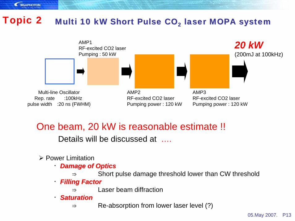
Multi 10 kW Short Pulse COMulti 10 kW Short Pulse CO22 laser MOPA systemlaser MOPA system
Power Limitation・Damage of OpticsDamage of Optics
⇒ Short pulse damage threshold lower than CW threshold・Filling FactorFilling Factor
⇒ Laser beam diffraction・SaturationSaturation
⇒ Re-absorption from lower laser level (?)
One beam, 20 kW is reasonable estimate !!Details will be discussed at ….
AMP3RF-excited CO2 laserPumping power : 120 kW
AMP2RF-excited CO2 laserPumping power : 120 kW
AMP1RF-excited CO2 laserPumping : 50 kW
Multi-line OscillatorRep. rate :100kHz
pulse width :20 ns (FWHM)
20 kW(200mJ at 100kHz)
Topic 2

05.May 2007. P14
Sn debris and mitigation
Experimental layout
Droplet debrisSn neutralFast ion
Deposition Minimized by CO2 irradiation
Sputtering Magnetic field mitigation
Debris from Sn laser plasma and mitigation
22.5deg
45deg
75deg
22.5deg
45deg
75deg
60deg
90deg
QCM (Deposition/sputter) Faraday Cup (Ion)
Si witness plate (debris)FC2(EUV energy)
TEA-CO2 laser
22.5deg
45deg
75deg
22.5deg
45deg
75deg
60deg
90deg
QCM (Deposition/sputter) Faraday Cup (Ion)
Si witness plate (debris)FC2(EUV energy)
TEA-CO2 laser
Plasmalens
Faraday-cup array
QCM array Plasmalens
Faraday-cup array
QCM array
Fundamental experiment device

05.May 2007. P15
-1.0E-030.0E+001.0E-032.0E-033.0E-034.0E-035.0E-036.0E-037.0E-038.0E-039.0E-03
0 15 30 45 60 75 90
Observation angle [deg]
sput
ter &
dep
ositi
on ra
te[n
m/m
J]
Nd:YAGCO2
Deposition
Sputtering
CO2 laser is clean LPP driver compared to YAG
Deposition case
Sputter / deposition rate measured by QCM
Deposition
No deposition
Fundamental experiment device
Mo/Si sample test
Topic 3

05.May 2007. P16
TEA-CO2 Laser
•Mo/Si mirror sample :10 bilayer•Distance from plasma: 120mm•Angle to laser incidence: 30 degree•Laser pulse energy: 15-25mJ•Laser pulse number: 1.5×10⁵ pulse•Chamber pressure: 5×10⁻² Pa
Mo/Si sample mirror test Experimental setup
Mo/Si mirror
Fundamental experiment device
TEM class sectional image of the exposed Mo/Si
4-nm uniform Sn deposition
Sn plate
Low density Sn deposition; since the measured reflectivity change is much smaller than the calculated reflectance for 4nm solid Sn.
Topic 3

05.May 2007. P17
CO2
Yag ω
1/100
Cut off density :Nc
1
Laser Electron critical density (cm-3)
CO2 (10.6um) 1.0x10¹⁹
Nd:YAG (1.06um)
1.0x10²¹
CO2 laser light is efficiently absorbed by low density plasma, therefore thermal boiling of Sn (cause of Sn drops creation) is avoided.
Distance0
Elec
tron
dens
ity
Laser
Laser plasma interaction region
X-ray emission
Hot dense plasma
nc
Distance0
Elec
tron
dens
ity
Laser
Laser plasma interaction region
X-ray emission
Hot dense plasma
nc
Efficient EUV is emitted from hot dense plasma near the electron critical density nc.
2
20
c emn ωε
=
)cm(1011.1n 32
21
c−
λ×
= λ: wavelength in μm
CO2 laser is clean LPP driver compared to YAGFundamental experiment device
05.May 2007. P18
Introduction - LPP source roadmap and concept
Update of CO2 laser produced Sn plasma source - Laser output power- Sn deposition analysis- System scalability
LPP/EUV future direction to HVM
Summary
OutlineOutline

05.May 2007. P19
LPP Power RoadmapCE %
Laser kW 2.0 2.2 2.5 3.0 3.5 4.0 4.52.5 14 15 18 21 25 28 32
18 20 23 27 32 36 415.0 28 31 35 42 49 56 63
36 40 45 54 63 72 817.5 42 46 53 63 74 84 95
54 59 68 81 95 108 12210.0 56 62 70 84 98 112 126
72 79 90 108 126 144 162HVM source
Transfer efficiency from primary source to IF
Total Debrisshield
Collectableangle Reflectivity T% SPF
Case1 0.28 0.8 5sr 0.6 0.9 0.8Case2 0.36 1 4sr 0.6 0.94 1
LPP/EUV future direction to HVM (1)
EUV power estimation with laser power & CE
HVM-source

05.May 2007. P20
Mirror lifetime estimation based on Rep.rate : 100kHz, CO2 laser w/o pre-pulse Mirror : Mo/Si 250 bilayer , 22.5deg(worst place) Plasma-mirror distance : 150mm Magnetic field effect :×1000
10
100
1000
0 50 100 150 200 250
IF power [W]
mirr
or li
fetim
e [B
pls]
Lifetime requirements (12months) : 80Bpls@10kHz ⇒ 800Bpls@100kHz
701 Bpls (10.5months)
350 Bpls (5.2months)
175 Bpls (2.6months)
87 Bpls (1.3months)
Collector mirror lifetime estimation based on this work
Tool duty: 25%
7days 24H operation
LPP/EUV future direction to HVM (2)
HVM-source

05.May 2007. P21
LPP technology update summaryLPP power by EUVA set up – (non-integrated setup)
40W@I/F is achieved at Q4 2006. Now 47W@I/F equivalent!By CO2 laser (6kW→7kW) produced Sn plasmaTarget: solid Sn diskSource power 110 W→130W, 2p sr, 2%bw
20KW driver laser scalability is estimated.
Easier debris mitigation of CO2 laser produced Sn plasma175 Bpls factor 1000 (detection limit)
Estimated number by experimental setup.Need proven data with system demonstration.
Very small damage on collector mirror is observed
For next stageSD (System Demonstration)-SoCoMo is under planning 90W (@ I/F) with CO2 laser and Sn droplet + debris mitigation+ Collector mirror