Embed Size (px)
Citation preview

CONTENTS . . . . . . . . . . . . . . . . . . . . . . . . . . . . . . . . .PAGE
Ratings and Dimensions . . . . . . . . . . . . . . . . . . . . . . . . . . .2Installation Requirements:
Boiler Location . . . . . . . . . . . . . . . . . . . . . . . . . . . . . . . .3Clearances . . . . . . . . . . . . . . . . . . . . . . . . . . . . . . . . . .3-4Vent Requirements . . . . . . . . . . . . . . . . . . . . . . . . . . . . .3Boiler Internal Baffles . . . . . . . . . . . . . . . . . . . . . . . . . . .3Vent Piping . . . . . . . . . . . . . . . . . . . . . . . . . . . . . . . . . . .3Installing Water trim . . . . . . . . . . . . . . . . . . . . . . . . . . . .3Piping . . . . . . . . . . . . . . . . . . . . . . . . . . . . . . . . . . . . . . .4Installing Burner . . . . . . . . . . . . . . . . . . . . . . . . . . . . . . .5Oil Supply Piping . . . . . . . . . . . . . . . . . . . . . . . . . . . . . .6Wiring the Boiler . . . . . . . . . . . . . . . . . . . . . . . . . . . . . . .6
Operating Instructions:Precautions Before Starting . . . . . . . . . . . . . . . . . . . . . .6Start-up . . . . . . . . . . . . . . . . . . . . . . . . . . . . . . . . . . . . . .6Cleaning and Filling New Water Boiler . . . . . . . . . . . . . .6Wiring Diagrams . . . . . . . . . . . . . . . . . . . . . . . . . . . .7-11
Burner Data:Riello . . . . . . . . . . . . . . . . . . . . . . . . . . . . . . . . . . . . . . .12
Care and Maintenance:Extended Shutdown . . . . . . . . . . . . . . . . . . . . . . . . . . .14Freezing Protection . . . . . . . . . . . . . . . . . . . . . . . . . . . .14Oil Burner . . . . . . . . . . . . . . . . . . . . . . . . . . . . . . . . . . .14General Maintenance . . . . . . . . . . . . . . . . . . . . . . . . . .14
SAFETY WARNING:
KEEP BOILER AREA CLEAR AND FREE FROM COMBUSTIBLE MATERIALS, GASOLINE AND OTHER FLAMMABLE VAPORS AND LIQUIDS. FAILURE TO ADHERE TO ABOVE SAFETYWARNING, MAY RESULT IN PERSONAL INJURY OR DEATH AND PROPERTY DAMAGE.
IMPORTANT: The installation of this equipment must conformto the requirements of the authority having jurisdiction or, inthe absence of such requirements, to the Installation of OilBurning Equipment, ANSI/NFPA 31, latest edition, and to theNational Electrical Code ANSI/NFPA 70, latest edition. Theinstallation must also conform to the additional requirements inthis Slant/Fin Instruction Manual. Where there is any differ-ence, the more stringent requirement shall govern.
In addition, where required by the authority having jurisdiction,the installation must conform to American Society ofMechanical Engineers Safety Code for Controls and SafetyDevices for Automatically Fired Boilers, No. CSD-1, latest edition.
THIS MANUAL MUST BE LEFT WITH OWNER ANDSHOULD BE HUNG ON OR ADJACENT TO THE
BOILER FOR REFERENCE.
IMPORTANT: This boiler must be installed by a trained, experienced, service technician, licensed for the installationand servicing of oil burning equipment or otherwise qualified bythe authorities having jurisdiction over the installation.
Part No. 470908000 Publication No. EC-10DV-40 Rev.CPrinted in U.S.A. 1116
THIS BOILER OPERATES WITH POSITIVE PRESSURE INTHE FLUE AND OVER FIRE, ALL SEALS MUST BE INPLACE WHEN OPERATING THE BOILER. ALL VENTINGMUST BE INSTALLED AND SEALED ACCORDING TO THEVENT MANUFACTURER’S INSTRUCTIONS.
DIRECT VENT OIL-FIRED WATER BOILER/NO. 2 OILINSTALLATION AND OPERATING INSTRUCTIONS
EUTECTIC EC-10DV Series
CAUTIONThe information in this manual must be followed exactlyto avoid personal injury, property damage or loss of life.
SEE BACK COVER FORSERVICE PERSONNEL

2 EUTECTIC EC-10 DV
Maximum operating pressure 60 psi (414 kPa).All boilers hydrostatically tested — A.S.M.E.* For forced hot water heating systems where the boiler and all piping are
located within the area to be heated, the boiler may be selected on the basisof D.O.E. capacity output. The net AHRI output ratings shown are based onan allowance for piping and pickup of 1.15 (water). D.O.E. capacity output isdivided by the allowance to obtain net rating. The Slant/Fin Technical Servicedepartment should be consulted before selecting a boiler for unusual pipingand pickup requirements such as intermittent system operation, extensivepiping, etc.
† Ratings apply to the use of light oil at 140,000 Btu per gallon and apply onlywhen burner models listed on pages 8 of this manual are used, and areproperly adjusted to produce 13% CO2.
# All dimensions subject to normal manufacturing tolerance.NOTE: All boilers under 300,000 Btuh (87.9 kw) input are tested and rated forcapacity under the U.S. Department of Energy (D.O.E.) Test Procedures forBoilers.
TABLE 1: Ratings and Dimensions
Figure 1: Dimensions (inches)
1-1/4 threadedsupply
Flue outlet øD
1-1/4 threadedreturn pipe
Drain outlet
Relief valve 3/4’’
Supply Pipe MountedTridicator
Panel MountedTridicator PressureSensor Well
Panel MountedTridicator TemperatureSensor Well
A
289mm
570mm
835m
m
570mm
265m
m
355mm 195mm
113m
m
156mm
563m
m
394m
m
128m
m
285mm
29mm
60mm
163mm
BOILERMODEL
NO.OIL INPUT † § GROSS
OUTPUT*NET
OUTPUT* AFUE%
DIMENSIONSAPPROX.OVERALLLENGTH
BOILERLENGTH
BOILERLENGTH FLUE DIA
DISTANCEBETWEEN
LEGS
FLUEOUTLETLENGTH
"A" "B" "C" "D" "E" "F"GPH mL/s BTU/H Watts MBH kW MBH kW in mm in mm in mm in mm in mm in mm
EC-13DV 0.68 0.72 91,000 26,672 79 23 69 20 87 36 914 22-1/4 25 27 686 5 127 11-13/16 300 2 51
EC-14DV 0.80 0.84 112,000 32,837 98 29 85 25 87 41 1041 27-1/4 25 32 813 5 127 16-13/15 300 2 51
EC-15DV 1.00 1.05 140,000 41,034 123 36 107 31 87 46 1168 32-1/4 25 37 940 5 127 21-13/16 427 2 51
EC-16DV 1.21 1.15 161,000 47,189 141 41 123 36 87 51 1295 37-1/4 25 42 1067 6 152 26-13/16 427 4 102

EUTECTIC EC-10 DV 3
BOILER LOCATION
CAUTION: NEVER BURN GARBAGE OR PAPER IN THEUNIT, AND NEVER LEAVE COMBUSTIBLE MATERIALAROUND IT.
Provide a level, solid foundation for the boiler.
A. The foundation must be capable of supporting the weight of the boiler when filled with water:
* Includes burner, circulator and controls
B. These boilers have full wet base sections which surround fire box formaximum heat absorption of burning fuel, and low floor temperature.
C. The boiler can be installed on both combustible and non-combustible floors, but must NOT be installed on or above carpeting.
D. If boiler is to be located over buried conduit containing electric wires or telephone cables, consult local codes or the National Board of FireUnderwriters for specific requirements.
MINIMUM CLEARANCEProvide accessibility clearance of 24" from surfaces requiring servicing (topand front) and 20" on any side requiring passage. The boiler shall beinstalled with the following MINIMUM clearances from combustible materials:BACK-6"SIDES-2" NOTE: Except in closets and alcoves, clearances above may be reduced byproviding forms of protection as specified in NFPA 31, latest edition.
VENTING REQUIREMENTS
CAUTION: AN OIL-FIRED UNIT SHALL BE CONNECTED TOA VENT HAVING SUFFICIENT DRAFT AT ALL TIMES TOENSURE SAFE AND PROPER OPERATION OF THE UNIT.
• The terminal shall not be closer than 3 feet above or 10 feet horizontally from any forced air inlet into the building.
• The terminal shall not be closer than 4 feet below, 4 feet horizontally or 1 foot above any door, window or gravity air inlet into the building.
• The terminal shall not be less than 3 ft from an inside corner of an “L” shaped building.
• The terminal shall not be less than 7 ft above grade when located adjacent to public walkways.
• The terminal shall not be less than 2 ft from an adjacent building.• The terminal shall be located at a height not liable to blockage from leaves,
snow or other debris, at least 1 ft above grade or anticipated snow line.• The terminal shall be positioned so that flue gases are not directed where
they can jeopardize people, overheat combustible structures or enterbuildings.
• Vent terminal should be away from shrubbery or other obstructions that would prevent free air flow to and from vent terminal. Do not terminate vent under decks, stairways or car ports. When ever possible, locations under windows should be avoided.
• Vent termination should not be mounted directly above or within 3 ft horizontally from an oil tank vent.
BOILER INTERNAL BAFFLESIMPORTANT: EC-10 series boilers Direct Vent version is different fromstandard series. Direct Vent version boilers usually have fewer internal castiron baffles.
VENT PIPINGA. The vent piping minimum bend radius is 12”.B. Place metal strapping every 36” to support vent pipe and
prevent it from sagging.C. Maximum wall thickness is 14”. Contact Slant/Fin Corp. for
recommendations in case of thicker wall.D. Gases will form white plume in winter. Plume could obstruct
window view.E. Prevailing winds could cause freezing of condensate and water/ice
buildup on building, plants or roof.F. Locate or guard vent to prevent accidental contact by people or pets,
and condensate from damaging exterior finish.G. Do not terminate vent in window well, stairwell, alcove, courtyard
or other recessed areas.
All venting kits must be double wall construction for the flue gas piping. FieldControls is the only approved manufacturer for venting kits. When installingthe vent kits the manufacturers instructions must be followed.
INSTALLING WATER TRIMNotes: Jacket must be installed on boiler units prior to installation of trim.
INSTALLATION REQUIREMENTS
Boiler Approximate Total Weight of BoilerSize Assembly*, filled with water
EC-13-DV 353EC-14-DV 426EC-15-DV 501EC-16-DV 575
Standard Version Direct Vent Version
EC-13 (3) Baffle Plates
(2) Baffle Plates cen-ter & right side
when viewing fromfront
EC-14 & 15
(2) Baffle Platescenter & right sidewhen viewing from
front
(0)
EC-16 (0) (0)
IMPORTANT: For correct installation of directvents, see publication # ECDV40-V, “VentingInstallation Instructions.” Information below sum-marizes the requirements.
4 EUTECTIC EC-10 DV
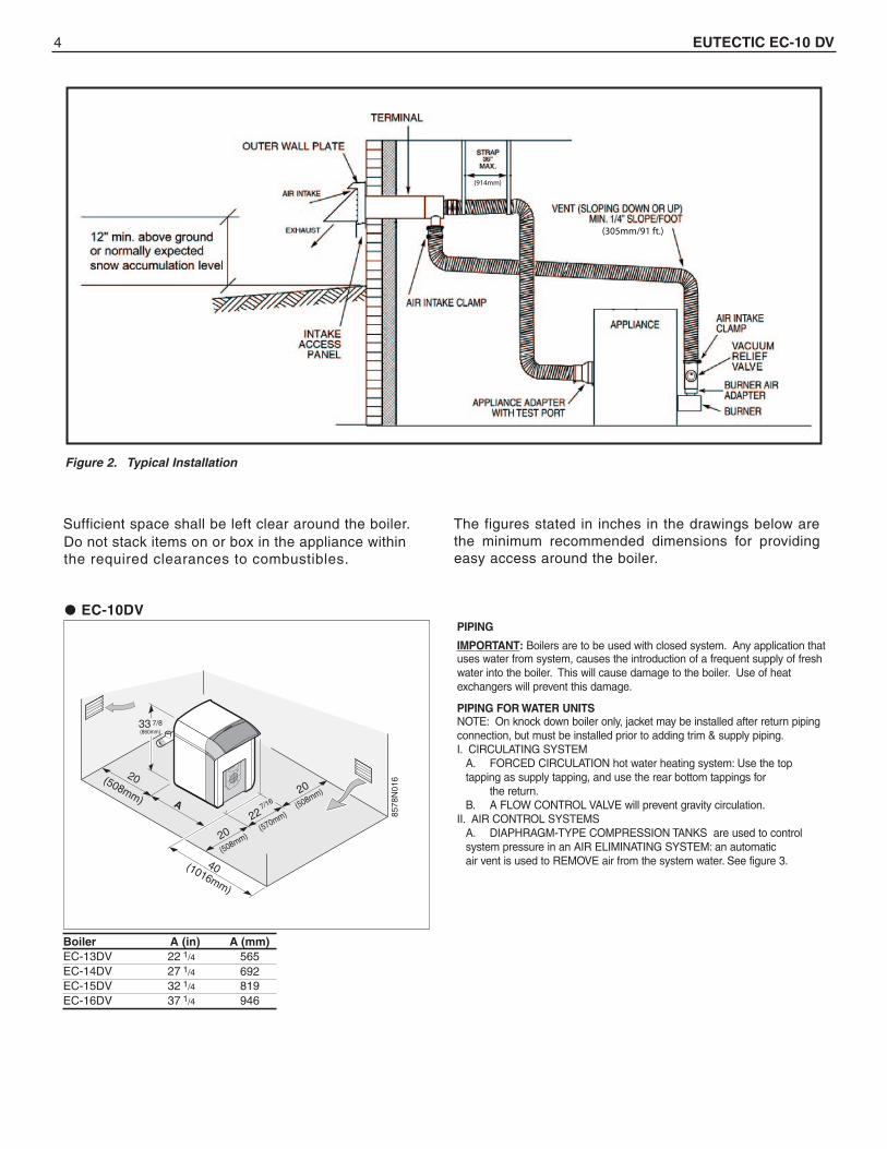
Sufficient space shall be left clear around the boiler. The figures stated in inches in the drawings below arethe minimum recommended dimensions for providingeasy access around the boiler.
8578
N01
620
A
40
22 7/16
20
20
33 7/8
Boiler A (in) A (mm)EC-13DV 22 1/4 565
1/4 692EC-14DV 27EC-15DV 32 1/4 819EC-16DV 37 1/4 946
EC-10DV
Do not stack items on or box in the appliance withinthe required clearances to combustibles.
(508mm)
(1016mm)
(508mm)(570mm)
(508mm)
(860mm)
(914mm)
(305mm/91 ft.)
Figure 2. Typical Installation
PIPING
IMPORTANT: Boilers are to be used with closed system. Any application thatuses water from system, causes the introduction of a frequent supply of freshwater into the boiler. This will cause damage to the boiler. Use of heatexchangers will prevent this damage.
PIPING FOR WATER UNITSNOTE: On knock down boiler only, jacket may be installed after return pipingconnection, but must be installed prior to adding trim & supply piping.I. CIRCULATING SYSTEM
A. FORCED CIRCULATION hot water heating system: Use the top tapping as supply tapping, and use the rear bottom tappings for
the return.B. A FLOW CONTROL VALVE will prevent gravity circulation.
II. AIR CONTROL SYSTEMSA. DIAPHRAGM-TYPE COMPRESSION TANKS are used to control system pressure in an AIR ELIMINATING SYSTEM: an automatic air vent is used to REMOVE air from the system water. See figure 3.

EUTECTIC EC-10 DV 5
If system pressure needs further control, add an additional tank or install a larger capacity tank. The automatic air vent should be installed in the top of the boiler, as in figure 3.
B. CONVENTIONAL COMPRESSION TANKS (non-diaphragm type) are used to control system pressure in an AIR COLLECTING SYSTEM. Within the system, after initial start-up and venting, air is collected in the tank and acts in contact with the water to control pressure. Air is not vented from this system. If system pressure needs further control, add another tank inparallel with the original tank or install a large capacity tank. Locate the tank at the inlet end of the pump near the boiler. (See figure 3)
C. HOT WATER RADIATION VENTING - Manual air vents should be installed at the top of all "drops" (where piping goes downward). Air must be vented or purged from all zone lines to permit proper system heating.
D. PUMP LOCATION - Locating low-head pump(s) on return to boiler is acceptable for smaller boiler sizes in residences of one or two stories.The pump location shown in figure 3 is required in large, multi-storybuilding installations, especially when high-head pumps are used.
IMPORTANT: Hot water heating systems containing high water volume, suchas would occur with cast iron radiation, require special care with air elimina-tion. The circulator pump should be located on the boiler supply pipe and theexpansion tank and air scoop should be located near the pump suction.
INSTALLING THE BURNERSee Burner Data, pages 12-13, and Burner Manual supplied with burner. Ifburner is not mounted as received, mount to boiler, placing flange overmounting studs. Use gasket between flange and boiler. Distance betweenflange and nose of burner must be as shown in table on page 12 (BurnerInsertion Depth). Check to see that nozzle and settings are as given in burnerdata tables, pages 12-13.
3⁄8 – – – 0.430 0.00751⁄2 40 0.622 0.0157 0.545 0.01215⁄8 – – – 0.666 0.01813⁄4 40 0.824 0.0277 0.785 0.02511 40 1.049 0.0449 1.025 0.0429
11⁄4 40 1.380 0.0779 1.265 0.065311⁄2 40 1.610 0.106 1.505 0.09242 40 2.067 0.174 1.985 0.161
21⁄2 40 2.469 0.249 2.465 0.2483 40 3.068 0.384 2.945 0.354
Nominalpipe Dia.
PipeSchedule
Pipe IDInch
Gal. perLin.Ft.
Pipe IDInch
Gal. perLin. Ft.
Standard Steel Pipe Copper Pipe
VOLUME OF WATER IN STANDARD PIPE OR TUBE
13-31/32(355mm) 7-11/16
(195mm)
Relief valve 3/4(19mm)
1/2” (13mm) NPT Tappingfor Feed Valve andExpansion Tank
1-1/4 (32mm) NPTreturn tapping
Drain outlet
Panel MountedTridicator Temperature
Sensor Well
Air Eliminatoras per ManufacturerSpecifications
To Circ. (s)and Zones
1-1/4”(32mm)
NPTSupply
AutomaticAir Vent
Suppy Pipe MountedTridicator
Panel MountedTridicator PressureSensor Well
Figure 3. Air Eliminating System or Alternating Collecting System. Pipe off to a safe place the relief valve and drain outlet.
EC-13 EC-14 EC-15 EC-16
5 6.5 8 8.5
WATER CONTENT OF BOILER (GALLONS)
BURNER INSERTION DEPTH

6 EUTECTIC EC-10 DV
CAUTION: DO NOT USE GASOLINE, CRANKCASEDRAININGS, OR ANY OIL CONTAINING GASOLINE.
OIL SUPPLY PIPINGInstall the oil tank or tanks and piping from tank to burner. Follow localcodes and practices, NFPA No. 31, INSTALLATION OF OIL BURNINGEQUIPMENT and the instruction sheet attached to the oil burner pump. Aone-pipe system should be used for gravity fed fuel systems and for lift sys-tems, where the total lift is less than 8 ft. Where the total lift is greater than 8ft., a two-pipe system must be used. In some instances, local codes mayrequire a two-pipe system for below grade fuel oil tanks. Be sure to set-upthe fuel oil pump for the piping system used; follow the instructions attachedto the pump. Be sure to include a good quality, low pressure drop fuel oil fil-ter in the supply line from the tank. This is necessary, especially at low fueloil flow rates (small nozzle sizes), to prevent nozzle plugging.
WIRING THE BOILER• The wiring diagrams for the burner and boiler may be found on pages 7-10.• 24 volt control wiring should be approved Safety Circuit wire, protected
as needed.• Power supply wiring to the burner must be 14 gauge or heavier, as
required, and should have a properly fused disconnect switch. 120 volt wiring to pumps and safety controls must also be 14 gauge or heavier. Wire must be enclosed in approved conduit.
• All wiring must be installed in compliance with the National Electric Code, or any local or insurance codes having jurisdiction.
Wiring to the boiler must come through an emergency powerisolation switch with a clearly marked red switch plate. Thisswitch should be located so that it is apparent to the home-owner when entering the basement or other boiler area. Thehomeowner should be made familiar with operating the toggleto provide or stop the power to the boiler.
PRECAUTIONS BEFORE STARTING OIL BURNERMake a positive check of A through I before starting burner:A. Boiler and system are full of water. All air is vented from system.
See below.B. All wiring is completed. See pages 7-10.C. Oil supply is connected to the burner; nozzle is installed correctly; oil
valve is open at tank.D. All combustible materials are cleared away.E. All vent piping is properly installed and sealed.F. Burner settings are adjusted as per pages 12-13 and as shown on
boiler jacket label.G. Main cast iron door on which burner is mounted is bolted shut and
fiberglass rope seal is making good contact.H. Make sure boiler has correct quantity of baffles (see top of page 3).I. Make sure vent pipe, vent terminal and air supply pipe are properly
installed and clear of obstruction.
Note: Neither overfire nor flue draft shouldexceed 0.35" WC during burner operation
THE FLUE IS UNDER POSITIVE PRESSURE DURINGOPERATION. ALL VENTING MUST BE SEALED AND
CHECKED ON A REGULAR INTERVAL.
OPERATING INSTRUCTIONS
CLEANING AND FILLING A NEW WATER BOILERI. BEFORE FILLING WATER BOILER
A. Check burner to be certain it is ready for firing. DO NOT FIRE into an empty boiler.
B. Be prepared to heat raw water to at least 180°F. as soon as it is introduced into the boiler. This procedure will remove dissolved, corrosive gases.
C. Provide drain line, with valve, from boiler. Use a bottom tapping. Line and drain must be suitable for handling caustic solution.
II. CLEANING WATER BOILER SYSTEMA. Use a commercial cleaning solution, such as Rhomar Hydro-Solv
9100 Cleaner as directed in product instructions.B. Use a commercial treatment solution, such as Rhomar Pro-Tek 922
Treatment as directed in product instructions.III. FILLING AND VENTING THE WATER BOILER
A. Refill the system with fresh water.B. Bring water temperature to at least 180° F. promptly.C. Circulate water through entire system.D. Vent the system, including the radiation.E. The boiler is now ready to be put into service or on standby.F. If brand-name air-control devices are used, venting instructions furnished with the devices should be followed.
IV. SAFETY CHECK FOR CONTROL SYSTEMHigh limit control test: Set thermostat high enough for boiler water temperature to reach high limit control setting. When this temperature is reached, the high limit switch should open, and the burner should shut off automatically. If the high limit does not operate to shut off the burner, the high limit or the wiring is faulty. Repair or replace immediately.
START-UP (COMBUSTION TEST INSTRUMENTS MUSTBE USED) THIS BOILER IS A POSITIVE PRESSURE BOILER.
A. Make sure the boiler is installed and wired properly and is fullof water.
B. The observation port cover is mounted on the hinged burnermounting door. NEVER touch the port cover or any surroundingsurfaces with hands. They may be HOT. Use tools. Loosen thescrew and swing cover to be able to insert probe through slot,when necessary. See the burner instructions for bleeding air, etc.
C. Take a smoke reading soon after starting burner. If smoke is not zero or trace, open air to clear smoke and let burner fire.
D. DO NOT ATTEMPT TO SET FIRE BY EYE. A smoke gun and acombustion analyzer must be used. Adjust the air to get approxi-mately 12% CO2 with a zero or trace smoke. Then check andrecord draft and flue temperature.
E. Make sure that the observation port cover is closed tight, theburner is secure. Turn burner on and off at least 3 times tocheck ignition.
EUTECTIC EC-10 DV 7
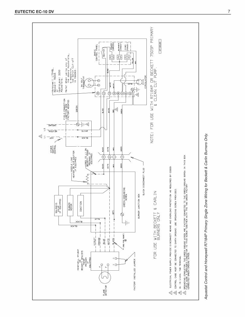
Aqu
asta
t C
ontr
ol a
nd H
oney
wel
l R71
84P
Prim
ary
Sin
gle
Zon
e W
iring
for
Bec
kett
& C
arlin
Bur
ners
Onl
y.
8 EUTECTIC EC-10 DV

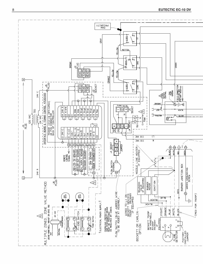
EUTECTIC EC-10 DV 9
EUTECTIC EC-10 DV 10
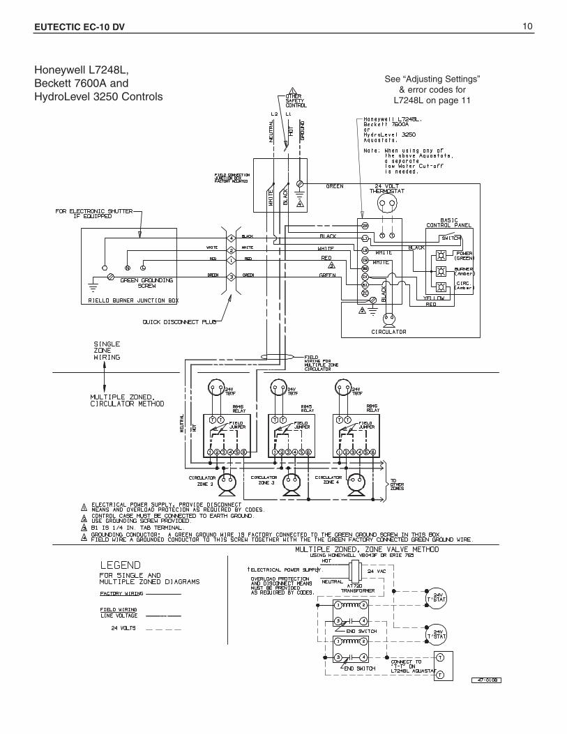
Honeywell L7248L,Beckett 7600A andHydroLevel 3250 Controls
See “Adjusting Settings”& error codes for
L7248L on page 11

11 EUTECTIC EC-10 DV
ADJUSTING SETTINGSTo discourage unauthorized changing of Aquastat settings, a procedureto enter the ADJUSTMENT mode is required. To enter the ADJUST-MENT mode, press the UP, DOWN, and I buttons simultaneously forthree seconds. Press the I button until the feature requiring adjustmentis displayed:
. HL_ . High Limit.
. LL_ . Low Limit. (L7224 only)
. Ldf . Low Limit Differential. (L7224 only)
. °F . °C.
.ELL_ External Low Limit (L7248L only)
Then press the UP and/or DOWN buttons to move the set point to thedesired value, to change between ˚F and C˚, or to enable (On) or dis-able (Off) the External Low Limit. After 60 seconds without any buttoninputs, the control will automatically return to the RUN mode.
DISPLAYIn the RUN mode, the Aquastat will flash .bt. (boiler temp) followed bythe temperature (i.e., 220), followed by °F or °C.
To read boiler settings, press the I key to read the parameter of interest.For example, press I High Limit(HL) is displayed, followed by a three-digit number, i.e., 220, followed by
°F or °C. Pressing the I button again (on L7224 models) will display theLow Limit (LL) followed by a three-digit number and the correspondingdegree designator.
After approximately 60 seconds without any key presses, the display willenter a dim display mode. To return to the bright display mode, simplypress any key.
DESCRIPTION
Boiler Temperature –
High Limit –
Low Limit –
Low Limit Differential –
Local Thermostat Status –
Enviracom Thermostat Status –
Error Code –
Degrees Fahrenheit –
Degrees Celsius –
FOR L7248L
a Warnings are generated to enunciate the system is not operating optimally, but the Aquastat is still operating and maintaining boiler temperature. In the instance where an Outdoor Reset Module is used, the warnings may indicate a reset curve setting error one or more features is not running optimally, and the Aquastat is reverting to default settings or has stopped running the Outdoor Reset algorithms. The warnings are cleared when the issue(s) is resolved.
b To clear Err 8 condition, depress and hold all three user keys simultaneously for 60 seconds. Err 8 condition clears and display returns to normal. Err 8 condition is designed to catch welded relays on the Aquastat and will normally only occur near end of life for the control. If Err 8 condition has occurred early in the controls life, be sure to check for voltage feedback to B1 when B1 should be off and check current draw on b terminal to be sure oil burner is not draw-ing excessive current. Err 8 condition will keep repeating if B1 fault is not cleared.
Aquastat noitcA/esuaCedoC rorrE
EnviraCOM Alarm
81.rosnes retaw kcehc ;tluaf rosnes tatsauqA1rrE
81.gniriw ™MOCarivnE kcehc ;tluaf MOCE2rrE
Err3 Excessive electrical noise or frequency out of range. Hardware fault; replace controller. 18, 58
46.egatlov/gniriw 1B kcehc ;tluaf 1B4rrE
95.caV 011 ,2L-1L kcehc ;eniL woL5rrE
Err6 a 29.esuf ecalper ,seriw MOCE kcehc ;esuF :gninraW
A/N.seulav tluafed ot teser ;fdL ,fdH ,LL ,LH ,MORPEE :gninraW7rrE
Err 8 b Repeated B1 fault (voltage present at B1 when output is turned off); check B1 wiring/voltage. 25
Err9 a Warning: Outdoor Reset System failure; communication to Outdoor Reset Module lost, Outdoor Reset Module failure, multiple outdoor temperature sensors detected on the bus, or outdoor temperature sensor failure. Check EnviraCOM wiring (1, 2, 3), check sensor wiring.
50, 53, 149
Err 10 a Warning: Boost Failure; Boost Mode active at least once per cycle for the last 60 consecutive cycles. Check Outdoor Reset curve settings.
150
Err 11 a DHW Module/Sensor failure; communication to DHW Module lost, DHW Module failure, or temperature sensor failure. Check EnviraCOM wiring (1, 2, 3), check sensor wiring.
146, 147, 148
IMPORTANTThis boiler is equipped with a feature that saves energy by reducing the boiler water tem-perature as the heating load decreases. This feature is equipped with an override which isprovided primarily to permit the use of an external energy management system that servesthe same function. THIS OVERRIDE MUST NOT BE USED UNLESS AT LEAST ONE OFTHE FOLLOWING CONDITIONS IS TRUE:• An external energy management system is installed that reduces the boiler watertemperature as the heating load decreases. • This boiler is not used for any space heating • This boiler is part of a modular or multiple boiler system having a total input of 300,000
BTU/hr or greater. • This boiler is equipped with a tankless coil.

12 EUTECTIC EC-10 DV
EC-13DV BF-3 Long 0.65 0.55 80*A Delavan 133 0 4.5 2 7"EC-14DV BF-3 Long 0.8 0.7 80*B Delavan 130 3 5.5 none 7"EC-15DV BF-5 Short 1 0.75 60*A Delavan 178 1 4.4 none 4-1/4"EC-16DV BF-5 Short 1.15 0.85 60*W Delavan 182 2 4.2 none 4-1/4"
Boiler Model
RielloBurnerModel
FiringRateGPH
Size(GPH)
Angle &Type Mfg.
Oil Pump(PSIG)
Approx.Head
Setting
Approx.Air
Setting
BoilerFlue
Baffle
BurnerInsertion
Depth
Nozzles
Models BF-3 & BF-5 Electrode Setting
Turbulator location
Picture 1.
TURBULATOR SETTING1. Loosen nut, 1, then turn the screw, 2, until the index marker, 3, is aligned with the correct index number.
2. Retighten the retaining nut, 1.
The numbers on the casting are there to denote the high and low end of the scale – For Model BF-5, zero and four are scale indicators only. From left to right, the first line is 4 and the last line is 0.
The air/oil ratio depends on accurate setting of the turbulator disc and air damper.
Be careful when making this adjustment as an incorrect setting will result in an unsatisfactory operation.See figure 5 & 6.
Figure 4.
3
2
1
RIELLO BURNER DATA
BlastTube

EUTECTIC EC-10 DV 13
SETTING THE AIR DAMPER ADJUSTMENT (see figure 7 & picture 2)
1. The initial air damper setting is made by turning screw (2) until the top edge of the air damper (3) is aligned with the number according to the burner setup chart.
2. Further adjustments can be made with the burner cover in place by removing plastic plug on the top right hand side of the cover. Turn the screw counter clockwise (+ indicator) to increase combustion air, turn the screw clockwise ( - indicator) to decrease combustion air.
3. The final position of the air damper will vary on each installation. Use instruments to establish the proper settings for maximum CO2 and a smoke reading of trace to zero.
NOTE: Variations in flue gas, smoke, CO2 and temperature readings may be experienced when the burner cover is put in place. Therefore, the burner cover MUST be in place when making the final combustion instrument readings, to ensure proper test results.
Picture 2. Air Damper LocationFigure 7. Air Damper Setting 3
2
1
Figure 5. Model F-5 Figure 6. Model F-3
14 EUTECTIC EC-10 DV
CARE AND MAINTENANCEI. EXTENDED SHUTDOWN, CLEANING OR REMOVAL OF
BOILER FROM SERVICE.DANGER: Use CAUTION when handling chemicals anddraining hot water from a boiler. Scalding water and/orchemicals can cause permanent injury to the skin, eyesand respiratory system.A.Shut down burner by disconnecting all electrical power to
the burner by turning OFF the BURNER EMERGENCYSWITCH of this boiler. After shutting down burner, whilethe boiler is still hot (180°F to 200°F), drain water fromthe bottom of the boiler until it runs clear.
B.Provide corrosion protection conditioning to the boiler waterin the heating system. There are a number of commercialheating system preparations available from your distributor.Follow the preparation manufacturer’s instructions.
C.To clean the fireside boiler surfaces, first shut downburner by disconnecting all electrical power to the burnerby turning OFF the OIL BURNER EMERGENCYSWITCH of this boiler in order to perform the followingwork in (1) through (10) below.1. Remove the flue pipe from the boiler flue collar and
clean thoroughly.2. Inspect the entire vent connector back to the chim-
ney and clean if necessary.3. Inspect the chimney for soot, debris and other unsafe
conditions of the chimney and take the necessaryaction.
4. The burner mounting door must be fully open to clean the flue passages and the combustionchamber. If the oil line is not flexible enough it should be disconnected from the burner during the cleaning process. The flexible electric conduit connected from the junction box on the boiler to the burner via a plastic connector must be disconnected from the burner by grasping the plastic half of the connector closest to the flexible conduit and gently pulling it in the direction of the conduit until it is disconnected. Remove all four 13 mm hex head screws on the sides of the swinging door. You will need a 13 mm open end or box wrench. Open the door tocompletely expose the combustion chamber forthorough cleaning and for inspection of main cast iron burner door insulation and burner door fiberglass sealing rope.
5. Use the flue brush to clean the flueways. Remove castiron baffle plates for cleaning [(2) baffle plates in EC-13, (0) baffle plates in EC-14, 15, and EC-16.]† A wirebrush may be used to remove any carbon accumula-tion that may have developed in the combustion cham-ber. Vacuum the loose soot and debris from the boiler.Replace baffle plates.
6. Inspect the burner combustion head. Clean if neces-sary and make sure all the adjustments are correct.(See burner data pages for the burner installed.)Replace oil nozzle with new one and readjust elec-trodes. To insure proper burner operation ONLY THENOZZLES SPECIFIED IN THIS MANUAL OR ONTHE BURNER LABEL SHOULD BE USED FORREPLACEMENT.
† A flue brush (triangular shape) is supplied with boiler.
7. Protect all of the fireside surfaces by swabbing withneutral mineral oil.
8. Close main cast iron burner door (door on whichburner is mounted). Make sure that the entire seal(fiberglass rope) is making good contact with theboiler casting when replacing four 13 mm hex headscrews and tightening.
D.If boiler room is damp, provide ventilation.
CAUTION: ALWAYS KEEP THE OIL SUPPLY VALVE SHUTOFF IF THE BURNER IS SHUT DOWN FOR AN EXTENDEDPERIOD OF TIME
II. PROVIDING PROTECTION FOR FREEZINGAnti-freeze is sometimes used in hydronic heating sys-tems to protect against freeze-up in the event of powerfailure, or safety control shutdown when the building isunoccupied. It should be recognized that unless the build-ing is kept above freezing temperature by some means,the plumbing system is not protected.
PROPYLENE GLYCOL is used in the quick-freeze foodindustry; it is practically non-toxic. Its use may be permittedwhen indirect water heaters are used. When anti-freezemust be used, inhibited propylene glycol is recommended.Useful information on the characteristics, mixing propor-tions, etc. of glycol in heating systems is given in TechnicalTopics No. 2A, available from the Slant/Fin website, go tohttp://slantfin.com. Go to library, select current literature,select boiler model. See related topics and selectantifreeze and hydronic systems. Consult glycol manufac-turers for sources of propylene glycol.
DO NOT USE ETHYLENE GLYCOL BECAUSE IT IS TOXIC.
III. OIL BURNERAll service to the oil burner, oil filter, oil strainer, etc., should be performed by a professionally trained service person. Inspect and clean annually and following anyperiod of improper operation. Recheck and adjust settings as specified for burner model and nozzle size. Set burnerair using test instruments to obtain recommended CO2 anddraft without smoke. See the Burner Data page in this manual that corresponds to the burner installed.
IV. GENERAL MAINTENANCEThese operations are recommended to be performed atregular intervals:A.BOILER HEATING SURFACES: clean off all coatings
found. Reseal covers.B.BOILER CONTROLS: check settings, correct functioning.C.PIPING: check piping and accessories for leaks.D.STUB VENT and BREECHING: check for obstructions
and leaks.E.COMBUSTION AIR TO BURNER: check for continued
POSITIVE supply of air as required. Air needs are great-est in coldest weather. Refer to AIR SUPPLY,page 3.
F. WATER SYSTEM: check1. System to be full of water and pressure to remain
stable (between 12 psi and 25 psi).2. Air-control system: noise and air binding in radiation
should not occur.3. Water lines: slightest leaks should be corrected.
G.BOILER ROOM AIR SUPPLY: air vents should be openand free of obstruction.

SERVICE COMPANY
Name ______________________________
Address_____________________________
___________________________________
Telephone ___________________________
Model #_____________________________
Serial # _____________________________
SLANT/FIN CORPORATION, Greenvale, N.Y. 11548 • Phone: (516) 484-2600FAX: (516) 484-5921 • Canada: Slant/Fin LTD/LTEE, Mississauga, Ontario
www.slantfin.com
We Build Trust and Comfort
©Slant/Fin Corp. 2016 • Printed in the U.S.A. 1116 • Publication No. EC-10DV-40. Rev.C P/N 47-0908000