Embed Size (px)
Citation preview

EUSO General Meeting – Huntsville 19-23 May 2003
FEW WORDS ON AUGER-EUSO
Presented
by
Osvaldo Catalano

EUSO General Meeting – Huntsville 19-23 May 2003
Usual AUGER-EUSO comparison (2 different techniques involved: PS vs. FD)
What about comparing AUGER-EUSO using the same technique i.e. FDAUGER vs. FDEUSO ?
Little investigation on this subject follows
AUGER vs. EUSO

EUSO General Meeting – Huntsville 19-23 May 2003
AUGER FD PERFORMANCE
85% of events in STEREO
10% duty cycle
Turns out:
3 ev/year @ E 1020 eV
1 ev/year @ E 2*1020 eV
1 ev/10 year @ E 5*1020 eV
FD - AUGER vs. EUSO
EUSO 330 ev/year @ E 1020 eV 200 ev/year @ E 2*1020 eV 150 ev/3 year @ E 5*1020 eV

EUSO General Meeting – Huntsville 19-23 May 2003
FD - AUGER vs. EUSO Torpedo progression
# of events0.1 1 10
Yea
rs
2005
2006
2007
2008
2009
2010
2011
2012
1000
5 1020 eV 2 1020 eV 1020 eV
AUGER5 1020 eV 2 1020 eV 1020 eV
EUSO

EUSO General Meeting – Huntsville 19-23 May 2003

EUSO General Meeting – Huntsville 19-23 May 2003

EUSO General Meeting – Huntsville 19-23 May 2003

EUSO General Meeting – Huntsville 19-23 May 2003

EUSO General Meeting – Huntsville 19-23 May 2003

EUSO General Meeting – Huntsville 19-23 May 2003

EUSO General Meeting – Huntsville 19-23 May 2003
CONCLUSION
EUSO indeed helpful to AUGER for FD events cross check

EUSO General Meeting – Huntsville 19-23 May 2003
TEO STATUS
Presented
by
Osvaldo Catalano

EUSO General Meeting – Huntsville 19-23 May 2003
Power budgets
• Read-out Control Board
Secondary power 1.2 W (20% contingency included)
Operating voltage ± 5 V,+3.3 V , ±5% ripple
• Trigger Control Unit
Primary power 11 W x 2 units (10% contingency included)
EUSO General Meeting – Huntsville 19-23 May 2003
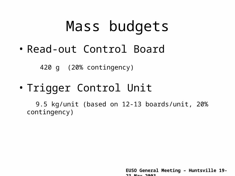
Mass budgets
• Read-out Control Board
420 g (20% contingency)
• Trigger Control Unit
9.5 kg/unit (based on 12-13 boards/unit, 20% contingency)
EUSO General Meeting – Huntsville 19-23 May 2003
ESA MTR Q/R
EUSO-EL-SP-001: 4.1.1 & 4.1.3.2 – Presence of high speed links between front-end ASICs and RO&C board – potential long signal wires
The cables between front-end ASIC and RO&C board will be less than 20 cm long. However the signals exiting from the ASIC are digital signals.

EUSO General Meeting – Huntsville 19-23 May 2003
EUSO-EL-SP-001: 4.1.3 – Front-end ASIC already well defined, however, the higher level electronics ( at micro- and macro-cell level and beyond ) not detailed. Do the microcells contain any circuitry or is it just a convenient definition? Are the logic elements going to be implemented in FPGAs? If so, what kind is envisaged and how many would be needed?
Any micro-cell is made of (as described in section 4.3.2) :
1) the sensors; 2) the LCS; 3) the voltage dividers; 4) the front-end electronics chip; 5) the connectors for HV/LV, signal and controls; 6) the base-board, a thick PCB housing all the other components; 7) any other required structural or functional element (e.g. components required to help heat transfers away from the micro-cell).
Macro-cell logic elements: Quantity Description Package
13 128k x 8 IC memory 32 pins FlatPack4 512k x 8 IC memory 36 pins FlatPack6 LVDS I/F 16 pins FlatPack1 FPGA 256 pins CerQuadFlatPack2-5 54HCXX (glue logic) 16 pins FlatPack1 ADC 8 bit 16 pins Flat Pack1 8 channels Analog MUX 16 pins FlatPack3 OP amps TO991 Voltage Reference TO99
• Passive components not included (most of them on bottom side of the PCB);• ASIC I/F (AFEE & DFEE) not included;• Preliminary list covering about 80% of estimated needs.

EUSO General Meeting – Huntsville 19-23 May 2003
EUSO-EL-SP-001: 4.2.1.3 – It was good to see a simulator exists for simulating the various triggering circuits and analyze the false alarm rates. It would be good to expand these simulations to include real events which need to be detected. One of the outputs would be to show the amount of data processing required at the various trigger levels up to the amount of data to be downloaded.
Simulators exist for simulating the various triggering circuits and analyze “fake” triggers. The outputs of the simulated trigger condition have driven the M.C. “ event” simulations. Work is in progress to estimate the data processing required at the various trigger levels up to the amount of data to be downloaded.

EUSO General Meeting – Huntsville 19-23 May 2003
WORK PLAN TO END OF PHASE A
Read-out Control Board components breakdown
Trigger Control Unit breakdown Update of the related documents

EUSO General Meeting – Huntsville 19-23 May 2003
AS STATUS
Presented
by
Osvaldo Catalano

EUSO General Meeting – Huntsville 19-23 May 2003
LIDAR CONFIGURATION

EUSO General Meeting – Huntsville 19-23 May 2003
Mass & Power budgets
Laser 70 kgTelescope 20 kgCoelostat 30 kgDetection module 40 kg
TOT 160 kg

EUSO General Meeting – Huntsville 19-23 May 2003
ESA MTR A/Q
Numerous questions from MTR panel
See livelink document
“General_ReplyTOComments”

EUSO General Meeting – Huntsville 19-23 May 2003
WORK PLAN TO END OF PHASE A
Mass and power budgets including contingencies
Detailed design of the receiver, transmitter and coelostat mechanism
Update of the LIDAR document

EUSO General Meeting – Huntsville 19-23 May 2003
System Electronics - TEO
Presented
by
Osvaldo Catalano

EUSO General Meeting – Huntsville 19-23 May 2003
Draft of the updated “Phase A Specification and Design Document for the EUSO Electronics” available.
Draft of the document will be circulated later on
Comments, suggestions and corrections expected by the 9th of June
Documentation status

EUSO General Meeting – Huntsville 19-23 May 2003
TEO News
“Analog” trigger included in the trigger scheme
Persistency algorithm revisited taking into account possible “holes” in the persistency pattern
Trigger Simulation (including diffuse background) on progress

EUSO General Meeting – Huntsville 19-23 May 2003
What next
Design of a Trigger emulator on small scale under way (in view of trigger algorithm verification and improvements)
Breadboard of ROC board foreseen at the beginning of phase B

EUSO General Meeting – Huntsville 19-23 May 2003
Support Activities - Background
• Background Measurement with BABY balloon flights (1998-2001-2002)
• BABY 2002 launched the 11 July (clear sky- Moonless)
• Change of Background expected in presence of clouds ( ?? %)

EUSO General Meeting – Huntsville 19-23 May 2003

EUSO General Meeting – Huntsville 19-23 May 2003
EUSO General Meeting – Huntsville 19-23 May 2003
• BABY detector and now UVscope available for new BKG observations (if needed)
• BABY already suitable for operating in Space. Little modification for UVscope (mainly mechanics envelope)
Pick-a-back (for ex. Shuttle) viable?
What next?