Embed Size (px)
Citation preview
ETA-Danmark A/S Kollegievej 6 DK-2920 Charlottenlund Tel. +45 72 24 59 00 Fax +45 72 24 59 04 Internet www.etadanmark.dk
MEMBER OF EOTA
Authorised and notified according to Article 10 of the Council Directive 89/106/EEC of 21 December 1988 on the approximation of laws, regulations and administrative provisions of Member States relating to construction products
European Technical Approval ETA-08/0165
This ETA replaces the previous ETA with the same number and validity from 2009-09-22 to 2014-09-22 Trade name:
GAH Angle Brackets (8612, 8613, 8614, 8615, 8617, 8620, 8621, 8623, 8624, 8625, 8626, 8627) GAH Angle Brackets (8634, 8635, 8636, 8637, 8638, 8640, 8641, 8644, 8645) GAH Angle Brackets with rib (8622, 8628, 8629, 8632, 8633, 8654, 8655)
Holder of approval: Gust. Alberts GmbH & Co KG Gewerbegebiet Grünenthal D-55845 Herscheid Tel. +49 2357 907 0 Fax +49 2357 907 189 Internet www.gah.de
Generic type and use of con-struction product:
Three-dimensional nailing plate (angle bracket for wood to wood connections)
Valid from: to:
2013-01-02 2018-01-02
Manufacturing plant: Gust. Alberts GmbH & Co KG Gewerbegebiet Grünenthal D-55845 Herscheid
This European Technical Approval contains:
36 pages including 2 annexes which form an integral part of the document

Page 2 of 36 of European Technical Approval no. ETA-08/0165
I LEGAL BASIS AND GENERAL CONDITIONS
1 This European Technical Approval is issued by
ETA-Danmark A/S in accordance with: - Council Directive 89/106/EEC of 21 December
1988 on the approximation of laws, regulations and administrative provisions of Member States relating to construction products1), as amended by Council Directive 93/68/EEC of 22 July 19932).
- Bekendtgørelse 559 af 27-06-1994 (afløser
bekendtgørelse 480 af 25-06-1991) om ikrafttræ-den af EF direktiv af 21. december 1988 om indbyrdes tilnærmelse af medlemsstaternes love og administrative bestemmelser om byggevarer.
- Common Procedural Rules for Requesting,
Preparing and the Granting of European Techni-cal Approvals set out in the Annex to Commis-sion Decision 94/23/EC3).
- EOTA Guideline ETAG 015 Three-dimensional
nailing plates, September 2002 edition. 2 ETA-Danmark A/S is authorized to check whet-
her the provisions of this European Technical Approval are met. Checking may take place in the manufacturing plant. Nevertheless, the responsi-bility for the conformity of the products to the European Technical Approval and for their fitness for the intended use remains with the holder of the European Technical Approval.
3 This European Technical Approval is not to be
transferred to manufacturers or agents of manu-facturers other than those indicated on page 1, or manufacturing plants other than those indicated on page 1 of this European Technical Approval.
4 This European Technical Approval may be
withdrawn by ETA-Danmark A/S pursuant to Article 5(1) of Council Directive89/106/EEC.
5 Reproduction of this European Technical Approval including transmission by electronic means shall be in full. However, partial reproduction can be made with the written consent of ETA-Danmark A/S. In this case partial reproduction has to be designated as such. Texts and drawings of advertising brochures shall not contradict or misuse the European Technical Approval.
6 This European Technical Approval is issued by ETA-
Danmark A/S in English. This version corresponds fully to the version circula-
ted within EOTA. Translations into other languages have to be designated as such.
1) Official Journal of the European Communities No L40, 11 Feb 1989, p 12. 2) Official Journal of the European Communities No L220, 30 Aug 1993, p 1. 3) Official Journal of the European Communities No L 17, 20 Jan 1994, p 34.

Page 3 of 36 of European Technical Approval no. ETA-08/0165
I SPECIAL CONDITIONS OF THE EUROPEAN TECHNICAL APPROVAL
1 Definition of product and intended use Definition of the product GAH angle brackets with and without rib are one-piece non-welded, face-fixed angle brackets to be used in timber to timber connections. They are connected to the timber elements by a range of profiled nails. The angle brackets are made from pre-galvanized steel DX 51 D / Z 275 according to EN 10327:2004 with a minimum yield strength Re of 250 MPa, a minimum tensile strength Rm of 330 MPa and a minimum ultimate strain A80 of 22 % and are available with or without an embossed rib. Dimensions, hole positions and typical installations are shown in Annex A. GAH angle brackets are made from steel with tolerances according to EN 10143. Additionally, the angle brackets can be made from stainless steel 1.4016, 1.4301, 1.4401, 1.4541 or 1.4571 according to EN 10088-2:2005 provided that the yield strength fy for these steel grades is at least the same as the minimum yield strength of the zinc coated steel normally used for the brackets. The ultimate strength fu and the ultimate strain A80 shall exceed the corresponding minimum values for the zinc coated steel. Intended use The angle brackets are intended for use in making connections in load bearing timber structures, as a connection between a beam and a purlin, where requirements for mechanical resistance and stability and safety in use in the sense of the Essential Requirements 1 and 4 of Council Directive 89/106/EEC shall be fulfilled. The connection may be with a single angle bracket or with an angle bracket on each side of the fastened timber member (see Annex A). The static and kinematic behaviour of the timber members or the supports shall be as described in Annex B. The wood members can be of solid timber, glued laminated timber and similar glued members, or wood-based structural members with a characteristic density from 290 kg/m3 to 420 kg/m3. This requirement to the material of the wood members can be fulfilled by using the following materials:
• Structural solid timber classified to C14-C40 according to EN 338 / EN 14081,
• Glulam classified to GL24-GL36 according to EN 1194 / EN 14080,
• LVL according to EN 14374, • Parallam PSL,
• Intrallam LSL, • Duo- and Triobalken, • Layered wood plates, • Plywood according to EN 636
Annex B states the load-carrying capacities of the angle bracket connections for a characteristic density of 350 kg/m3. For timber or wood based material with a lower characteristic density than 350 kg/m3 the load-carrying capacities shall be reduced by the kdens factor:
2
kdensk
350
ρ=
Where ρk ist he characteristic density of the timber in kg/m3. The design of the connections shall be in accordance with Eurocode 5 or a similar national Timber Code. The wood members shall have a thickness which is larger than the penetration depth of the nails into the members. The scope of the brackets regarding resistance to corrosion shall be defined according to national provisions that apply at the installation site considering environmental conditions. Section 2.7 of this ETA contains the corrosion protection for GAH Alberts angle brackets made from carbon steel and the material number of the stainless steel. The angle brackets may also be used for connections between a timber member and a member of concrete or steel. Assumed working life The assumed intended working life of the angle brackets for the intended use is 50 years, provided that they are subject to appropriate use and maintenance. The information on the working life should not be regarded as a guarantee provided by the manufacturer or ETA Danmark. An “assumed intended working life” means that it is expected that, when this working life has elapsed, the real working life may be, in normal use conditions, considerably longer without major degradation affecting the essential requirements.
Page 4 of 36 of European Technical Approval no. ETA-08/0165
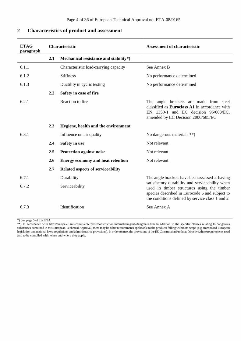
2 Characteristics of product and assessment
ETAG paragraph
Characteristic
Assessment of characteristic
2.1 Mechanical resistance and stability*)
6.1.1
Characteristic load-carrying capacity
See Annex B
6.1.2
Stiffness
No performance determined
6.1.3
Ductility in cyclic testing
No performance determined
2.2 Safety in case of fire
6.2.1
Reaction to fire
The angle brackets are made from steel classified as Euroclass A1 in accordance with EN 1350-1 and EC decision 96/603/EC, amended by EC Decision 2000/605/EC
2.3 Hygiene, health and the environment
6.3.1
Influence on air quality
No dangerous materials **)
2.4 Safety in use
Not relevant
2.5 Protection against noise
Not relevant
2.6 Energy economy and heat retention
Not relevant
2.7 Related aspects of serviceability
6.7.1
Durability
The angle brackets have been assessed as having satisfactory durability and serviceability when used in timber structures using the timber species described in Eurocode 5 and subject to the conditions defined by service class 1 and 2
6.7.2
Serviceability
6.7.3
Identification
See Annex A
*) See page 5 of this ETA **) In accordance with http://europa.eu.int-/comm/enterprise/construction/internal/dangsub/dangmain.htm In addition to the specific clauses relating to dangerous substances contained in this European Technical Approval, there may be other requirements applicable to the products falling within its scope (e.g. transposed European legislation and national laws, regulations and administrative provisions). In order to meet the provisions of the EU Construction Products Directive, these requirements need also to be complied with, when and where they apply.

Page 5 of 36 of European Technical Approval no. ETA-08/0165
Safety principles and partial factors The characteristic load-carrying capacities are based on the characteristic values of the nail connections and the steel plates. To obtain design values the capacities have to be multiplied with different partial factors for the material properties, in addition the nail connection with the coefficient kmod. According to EN 1990 (Eurocode – Basis of design) paragraph 6.3.5 the design value of load-carrying capacity can be determined by reducing the characteristic values of the load-carrying capacity with different partial factors. Thus, the characteristic values of the load–carrying capacity are determined also for timber failure FRk,H (obtaining the embedment strength of nails subjected to shear or the withdrawal capacity of the most loaded nail, respectively) as well as for steel plate failure FRk,S. The design value of the load–carrying capacity is the smaller value of both load–carrying capacities.
mod Rk,H Rk,SRd
M,H M,S
k F FF min ;
⋅=
γ γ
Therefore, for timber failure the load duration class and the service class are included. The different partial factors γM for steel or timber, respectively, are also correctly taken into account. 2.1 Mechanical resistance and stability See annex B for the characteristic load-carrying capacity in the different directions F1 to F5. The characteristic capacities of the angle brackets are determined by calculation assisted by testing as described in the EOTA Guideline 015 clause 5.1.2. They should be used for designs in accordance with Eurocode 5 or a similar national Timber Code. Threaded nails (ringed shank nails) in accordance to EN 14592 In the formulas in Annex B the capacities for threaded nails calculated from the formulas of Eurocode 5 are used assuming a thick steel plate when calculating the lateral nail load-carrying-capacity. The load bearing capacities of the brackets has been determined based on the use of connector nails 4,0 x 40 mm in accordance with the German national approval for the nails. The characteristic withdrawal capacity of the nails has to be determined by calculation in accordance with EN 1995-1-
1: 2004, paragraph 8.3.2 (head pull-through is not relevant): Fax,Rk = fax,k × d × tpen Where: fax,k Characteristic value of the withdrawal parameter in
N/mm2 d Nail diameter in mm tpen Penetration depth of the profiles shank in mm tpen ≥ 30 mm Based on tests by Versuchsanstalt für Stahl, Holz und Steine, University of Kalrsruhe, the characteristic value of the withdrawal resistance for the threaded nails used can be calculated as: fax,k = 50 × 10-6 × σk
2 Where: σk Characteristic density of the timber in kg/m3 The shape of the nail directly under the head shall be in the form of a truncated cone with a diameter under the nail head which exceeds the hole diameter. The design models allow the use of fasteners described in the table on page 9 in Annex A No performance has been determined in relation to ductility of a joint under cyclic testing. The contribution to the performance of structures in seismic zones, therefore, has not been assessed. No performance has been determined in relation to the joint’s stiffness properties - to be used for the analysis of the serviceability limit state. 2.7 Related aspects of serviceability 2.7.1 Corrosion protection in service class 1 and 2. In accordance with ETAG 015 the angle brackets are made from pre-galvanized steel DX 51 D / Z 275 according to EN 10327:2004 with minimum yield strength Re of 250 MPa, a minimum tensile strength Rm of 330 MPa and a minimum ultimate strain A80 of 22 % 2.7.2 Corrosion protection in service class 3. In accordance with Eurocode 5 the angle brackets are made from stainless steel 1.4016, 1.4301, 1.4401, 1.4541 or 1.4571 according to EN 10088-2:2005 and the nails shall be produced from stainless steel.

Page 6 of 36 of European Technical Approval no. ETA-08/0165
3 Attestation of Conformity and CE marking
3.1 Attestation of Conformity system The system of attestation of conformity is 2+
described in Council Directive 89/106/EEC (Construction Products Directive) Annex III.
a) Tasks for the manufacturer:
(1) Factory production control, (2) Initial type testing of the product,
b) Tasks for the notified body: (1) Initial inspection of the factory and the
factory production control, (2) Continuous surveillance 3.2 Responsibilities 3.2.1 Tasks of the manufacturer 3.2.1.1 Factory production control
The manufacturer has a factory production control system in the plant and exercises permanent internal control of production. All the elements, requirements and provisions adopted by the manufacturer are documented in a systematic manner in the form of written policies and procedures. This production control system ensures that the product is in conformity with the European Technical Approval. The manufacturer shall only use raw materials supplied with the relevant inspection documents as laid down in the control plan4. The incoming raw materials shall be subject to controls and tests by the manufacturer before acceptance. Check of materials, such as sheet metal, shall include control of the inspection documents presented by suppliers (comparison with nominal values) by verifying dimension and determining material properties, e.g. chemical composition, mechanical properties and zinc coating thickness. The manufactured components are checked visually and for dimensions. The control plan, which is part of the technical documentation of this European Technical Approval,
4 The control plan has been deposited at ETA-Danmark and is
only made available to the approved bodies involved in the conformity attestation procedure.
includes details of the extent, nature and frequency of testing and controls to be performed within the factory production control and has been agreed between the approval holder and ETA Danmark. The results of factory production control are recorded and evaluated. The records include at least the following information: - Designation of the product, basic material and
components; - Type of control or testing; - Date of manufacture of the product and date of
testing of the product or basic material and components;
- Result of control and testing and, if appropriate, comparison with requirements;
- Signature of person responsible for factory production control.
The records shall be presented to ETA Danmark on request.
3.2.1.1 Initial type testing of the product
For initial type-testing the results of the tests performed as part of the assessment for the European Technical Approval shall be used unless there are changes in the production line or plant. In such cases the necessary initial type testing has to be agreed between ETA Danmark and the notified body.
3.2.2. Tasks of notified bodies 3.2.2.1 Initial inspection of the factory and the factory production control
The approved body should ascertain that, in accordance with the control plan, the factory, in particular the staff and equipment, and the factory production control, are suitable to ensure a continuous and orderly manufacturing of the angle brackets with the specifications given in part 2.
3.2.2.2 Continuous surveillance
The approved body shall visit the factory at least twice a year for routine inspections. It shall be verified that the system of factory production control and the specified manufacturing processes are maintained, taking account of the control plan.
The results of product certification and continuous surveillance shall be made available on demand by the certification body to ETA Danmark. Where the provisions of the European Technical Approval and the control plan are no longer fulfilled, the certificate
Page 7 of 36 of European Technical Approval no. ETA-08/0165
of conformity shall be withdrawn by the approved body.
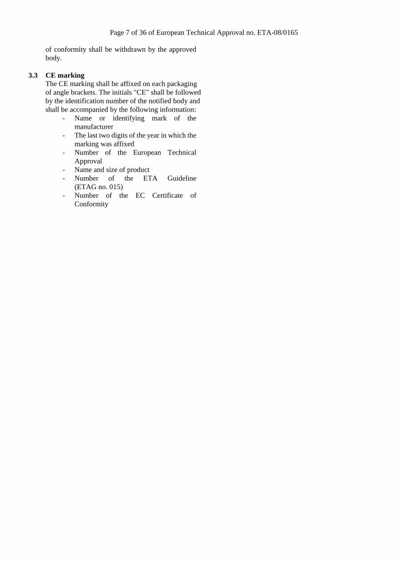
3.3 CE marking The CE marking shall be affixed on each packaging of angle brackets. The initials "CE" shall be followed by the identification number of the notified body and shall be accompanied by the following information:
- Name or identifying mark of the manufacturer
- The last two digits of the year in which the marking was affixed
- Number of the European Technical Approval
- Name and size of product - Number of the ETA Guideline
(ETAG no. 015) - Number of the EC Certificate of
Conformity

Page 8 of 36 of European Technical Approval no. ETA-08/0165
4 Assumptions under which the fitness of the product for the intended use was favourably assessed 4.1 Manufacturing GAH angle brackets are manufactured in accordance with the provisions of this European Technical Approval using the manufacturing processes as identified in the inspection of the plant by the notified inspection body and laid down in the technical documentation. 4.2 Installation The nailing pattern used shall be either the maximum or the minimum pattern as defined in Annex A. The following provisions concerning installation apply: The structural members – the components 1 and 2 shown in the figure on page 32 - to which the brackets are fixed shall be: • Restrained against rotation. At a load F4/F5, the
component 2 is allowed to be restrained against rotation by the Angle brackets.
• Strength class C14 or better, see section 1 of this ETA
• Free from wane under the bracket. • The actual end bearing capacity of the timber
member to be used in conjunction with the bracket is checked by the designer of the structure to ensure it is not less than the bracket capacity and, if necessary, the bracket capacity reduced accordingly.
• The gap between the timber members does not exceed 3 mm.
• There are no specific requirements relating to preparation of the timber members.
The execution of the connection shall be in accordance with the approval holder’s technical literature.
4.3 Maintenance and repair Maintenance is not required during the assumed intended working life. Should repair prove necessary, it is normal to replace the angle bracket.
Thomas Bruun Manager, ETA-Danmark

Page 9 of 36 of European Technical Approval no. ETA-08/0165
Annex A Product details definitions
Table A.1 Materials specification
Bracket type Thickness (mm)
Steel specification Coating specification
8612 2,5 DX 51 D / Z 275 Z 275
8613 2,5 DX 51 D / Z 275 Z 275
8614 2,0 DX 51 D / Z 275 Z 275
8615 2,0 DX 51 D / Z 275 Z 275
8617 2,5 DX 51 D / Z 275 Z 275
8620 2,0 DX 51 D / Z 275 Z 275
8621 2,5 DX 51 D / Z 275 Z 275
8623 3,0 DX 51 D / Z 275 Z 275
8624 2,5 DX 51 D / Z 275 Z 275
8625 2,5 DX 51 D / Z 275 Z 275
8626 3,0 DX 51 D / Z 275 Z 275
8627 2,5 DX 51 D / Z 275 Z 275
Bracket type Thickness (mm)
Steel specification* Coating specification
8634 2,5 DX 51 D / Z 275 Z 275
8635 2,5 DX 51 D / Z 275 Z 275
8636 2,0 DX 51 D / Z 275 Z 275
8637 2,5 DX 51 D / Z 275 Z 275
8638 2,5 DX 51 D / Z 275 Z 275
8640 2,5 DX 51 D / Z 275 Z 275
8641 2,5 DX 51 D / Z 275 Z 275
8644 2,5 DX 51 D / Z 275 Z 275
8645 2,5 DX 51 D / Z 275 Z 275
Bracket type Thickness (mm)
Steel specification* Coating specification
8622 2,5 DX 51 D / Z 275 Z 275
8628 2,5 DX 51 D / Z 275 Z 275
8629 2,0 DX 51 D / Z 275 Z 275
8632 2,5 DX 51 D / Z 275 Z 275
8633 2,5 DX 51 D / Z 275 Z 275
8654 2,5 DX 51 D / Z 275 Z 75
8655 2,5 DX 51 D / Z 275 Z 275

Page 10 of 36 of European Technical Approval no. ETA-08/0165
*Additionally, the angle brackets can be made from stainless steel 1.4016, 1.4301, 1.4401, 1.4541 or 1.4571 according to EN 10088-2:2005 provided that the yield strength fy for these steel grades is at least the same as the minimum yield strength of the zinc coated steel normally used for the brackets. The ultimate strength fu and the ultimate strain A80 shall exceed the corresponding minimum values for the zinc coated steel.

Page 11 of 36 of European Technical Approval no. ETA-08/0165
Table A.2 Range of sizes
Bracket type Height (mm) Width (mm)
min max min max
8612 40 60 60 60
8613 60 80 60 60
8614 80 80 40 40
8615 100 100 40 40
8617 60 100 60 60
8620 54,5 54 40 40
8621 48,5 51 35,5 35,5
8623 92 92,5 39,5 39,5
8624 69 69 55 55
8625 88,5 88,5 65 65
8626 97 98,5 90,5 90,5
8627 60 60 45 45
Bracket type Height (mm) Width (mm)
min max min max
8634 40,5 42 60 60
8635 60 61,5 40 40
8636 59,5 59 50 50
8637 60 61,5 60,5 60,5
8638 59 60 80 80
8640 79,5 80 60 60
8641 79,5 79,5 80 80
8644 100 100,5 80 80
8645 99,5 100 100 100
Bracket type Height (mm) Width (mm)
min max min max
8622 68,5 69,5 55 55
8628 150 150 65 65
8629 50 62 64 64
8632 88,5 89 65,5 65,5
8633 98 98,5 90 90
8654 51 90,5 80,5 80,5
8655 50,5 90,5 50 50

Page 12 of 36 of European Technical Approval no. ETA-08/0165
Table A.3 Fastener specification
Nail type Nail size (mm) Finish
According to EN 14592 Diameter Length
Threaded nail with a profiled length of at least 31 mm 4,0 40 Electroplated zinc

Page 13 of 36 of European Technical Approval no. ETA-08/0165
GAH Angle Bracket (8612, 8613, 8614, 8615, 8617, 8620, 8621, 8623, 8624, 8625, 8626, 8627)
Figure A.1 Dimensions of Angle Bracket 8612 Figure A.2 Dimensions of Angle Bracket 8613
Figure A.3 Dimensions of Angle Bracket 8614 Figure A.4 Dimensions of Angle Bracket 8615

Page 14 of 36 of European Technical Approval no. ETA-08/0165
Figure A.5 Dimensions of Angle Bracket 8617 Figure A.6 Dimensions of Angle Bracket 8620
Figure A.7 Dimensions of Angle Bracket 8621 Figure A.8 Dimensions of Angle Bracket 8623
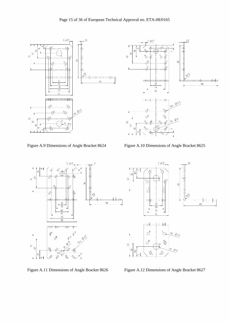
Page 15 of 36 of European Technical Approval no. ETA-08/0165
Figure A.9 Dimensions of Angle Bracket 8624 Figure A.10 Dimensions of Angle Bracket 8625
Figure A.11 Dimensions of Angle Bracket 8626 Figure A.12 Dimensions of Angle Bracket 8627
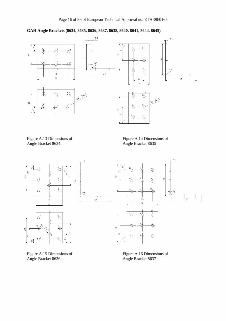
Page 16 of 36 of European Technical Approval no. ETA-08/0165
GAH Angle Brackets (8634, 8635, 8636, 8637, 8638, 8640, 8641, 8644, 8645) Figure A.13 Dimensions of Figure A.14 Dimensions of Angle Bracket 8634 Angle Bracket 8635
Figure A.15 Dimensions of Figure A.16 Dimensions of Angle Bracket 8636 Angle Bracket 8637

Page 17 of 36 of European Technical Approval no. ETA-08/0165
Figure A.17 Dimensions of Figure A.18 Dimensions of Angle Bracket 8638 Angle Bracket 8640
Figure A.19 Dimensions of Figure A.20 Dimensions of Angle Bracket 8641 Angle Bracket 8644
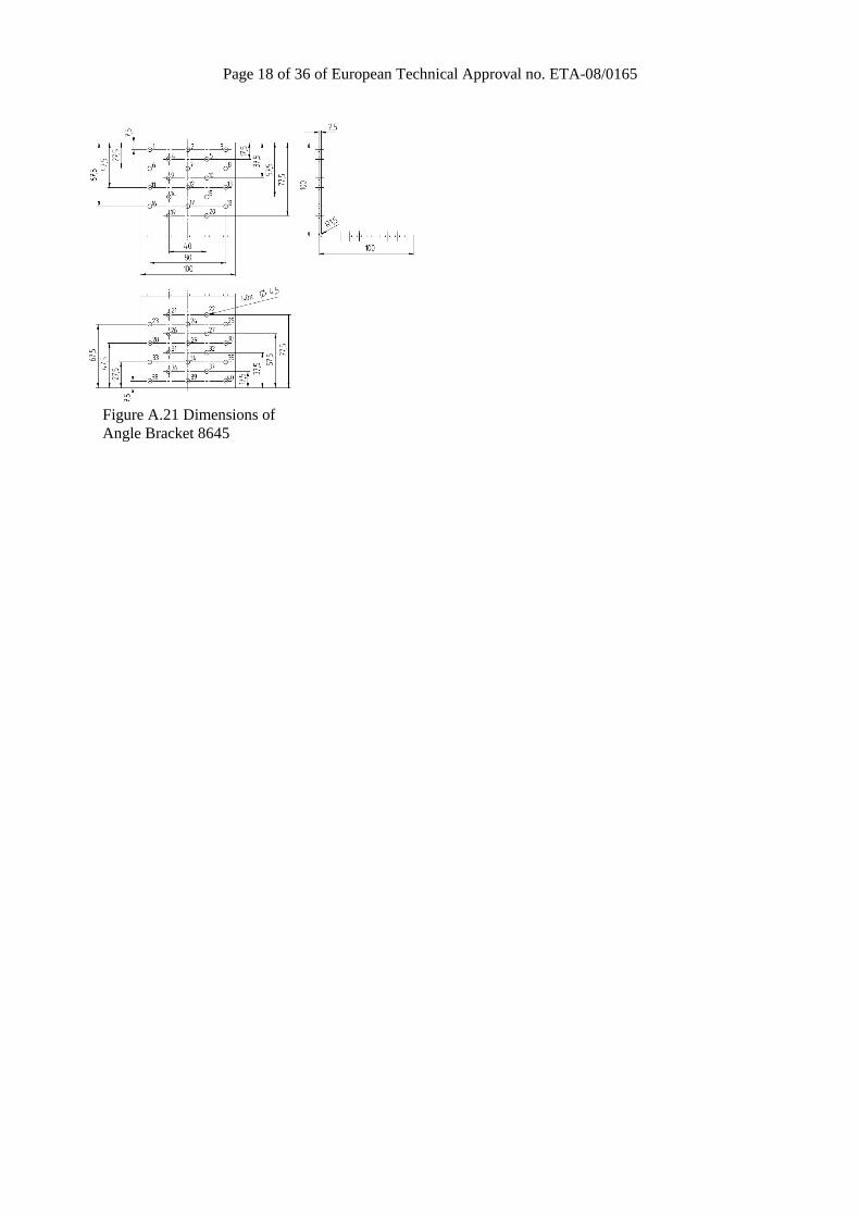
Page 18 of 36 of European Technical Approval no. ETA-08/0165
Figure A.21 Dimensions of Angle Bracket 8645
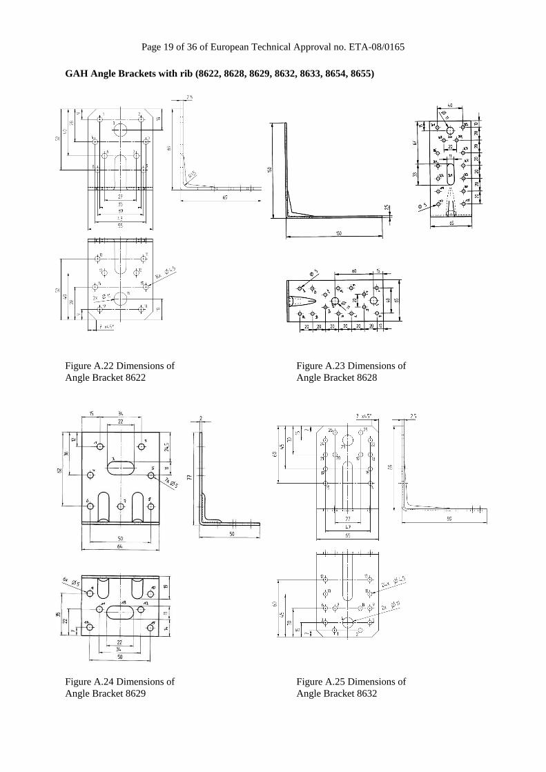
Page 19 of 36 of European Technical Approval no. ETA-08/0165
GAH Angle Brackets with rib (8622, 8628, 8629, 8632, 8633, 8654, 8655)
Figure A.22 Dimensions of Figure A.23 Dimensions of Angle Bracket 8622 Angle Bracket 8628 Figure A.24 Dimensions of Figure A.25 Dimensions of Angle Bracket 8629 Angle Bracket 8632

Page 20 of 36 of European Technical Approval no. ETA-08/0165
Figure A.26 Dimensions of Figure A.27 Dimensions of Angle Bracket 8633 Angle Bracket 8654
Figure A.28 Dimensions of Figure A.29 Typical installation Angle Bracket 8655
Page 21 of 36 of European Technical Approval no. ETA-08/0165
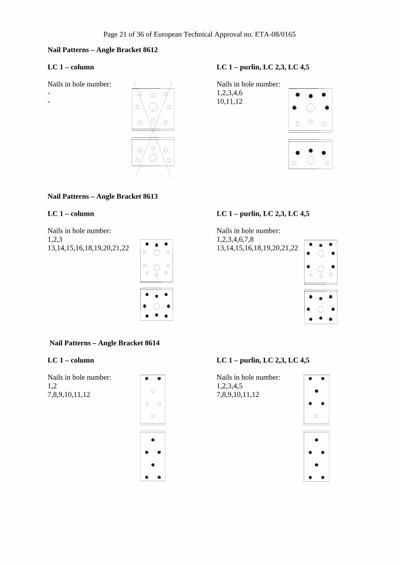
Nail Patterns – Angle Bracket 8612 LC 1 – column LC 1 – purlin, LC 2,3, LC 4,5 Nails in hole number: Nails in hole number: - 1,2,3,4,6 - 10,11,12
Nail Patterns – Angle Bracket 8613 LC 1 – column LC 1 – purlin, LC 2,3, LC 4,5 Nails in hole number: Nails in hole number: 1,2,3 1,2,3,4,6,7,8 13,14,15,16,18,19,20,21,22 13,14,15,16,18,19,20,21,22 Nail Patterns – Angle Bracket 8614 LC 1 – column LC 1 – purlin, LC 2,3, LC 4,5 Nails in hole number: Nails in hole number: 1,2 1,2,3,4,5 7,8,9,10,11,12 7,8,9,10,11,12

Page 22 of 36 of European Technical Approval no. ETA-08/0165
Nail Patterns – Angle Bracket 8615 LC 1 – column LC 1 – purlin, LC 2,3, LC 4,5 Nails in hole number: Nails in hole number: 1,2,3 1,2,3,4,5,6 7,8,9,10,11,12 7,8,9,10,11,12 Nail Patterns – Angle Bracket 8617 LC 1 – column LC 1 – purlin, LC 2,3, LC 4,5 Nails in hole number: Nails in hole number: 1,2,3,7,8,9 1,3,5,6,7,9,11,12 16,17,19,21,23,24 16,17,19,21,23,24
Nail Patterns – Angle Bracket 8620 LC 1 – column LC 1 – purlin, LC 2,3, LC 4,5 Nails in hole number: Nails in hole number: 1,2 / 5,6,7,8

Page 23 of 36 of European Technical Approval no. ETA-08/0165
Nail Patterns – Angle Bracket 8621 LC 1 – column LC 1 – purlin, LC 2,3, LC 4,5 Nails in hole number: Nails in hole number: 4,5 / 8,9,13,14 Nail Patterns – Angle Bracket 8623 LC 1 – column LC 1 – purlin, LC 2,3, LC 4,5 Nails in hole number: Nails in hole number: 1,2,6,7 / 1,2,6,7 / 11,12,14,15,19,20 11,12,16,17 Nail Patterns – Angle Bracket 8624 LC 1 – column LC 1 – purlin, LC 2,3, LC 4,5 Nails in hole number: Nails in hole number: 1,2 / 1,2,4,5 / 10,11,14,15,17,18 10,11,14,15,17,18

Page 24 of 36 of European Technical Approval no. ETA-08/0165
Nail Patterns – Angle Bracket 8625 LC 1 – column LC 1 – purlin, LC 2,3, LC 4,5 Nails in hole number: Nails in hole number: 1,2,10,11 / 1,2,6,9,12,13 / 14,15,18,21,25,26 14,15,22,24 Nail Patterns – Angle Bracket 8626 LC 1 – column LC 1 – purlin, LC 2,3, LC 4,5 Nails in hole number: Nails in hole number: 2,3,6,9 / 1,4,7,8,14,15 / 16,17,23,24,27,30 16,17,23,24 Nail Patterns – Angle Bracket 8627 LC 1 – column LC 1 – purlin, LC 2,3, LC 4,5 Nails in hole number: Nails in hole number: 1,2 / 1,2,4,5 / 8,9,10,11,13,14 8,9,10,11,13,14

Page 25 of 36 of European Technical Approval no. ETA-08/0165
Nail Patterns – Angle Bracket 8634 LC 1 – column LC 1 – purlin, LC 2,3, LC 4,5
Nails in hole number: Nails in hole number: 1,2,3 / 7,8,9,10,11,12
Nail Patterns – Angle Bracket 8635 LC 1 – column LC 1 – purlin, LC 2,3, LC 4,5
Nails in hole number: Nails in hole number: 1,2 / 1,2,3,4 / 7,8,9,10,11,12 7,8,9,10,11,12
Nail Patterns – Angle Bracket 8636 LC 1 – column LC 1 – purlin, LC 2,3, LC 4,5
Nails in hole number: Nails in hole number: 1,2 / 1,2,3,4,5 / 9,10,11,12,13,14,15,16 9,10,11,12,13,14,15,16
Nail Patterns – Angle Bracket 8637 LC 1 – column LC 1 – purlin, LC 2,3, LC 4,5 Nails in hole number: Nails in hole number: 1,2,3 / 1,2,3,4,5,6 / 10,11,12,13, 10,11,12,13, 14,15,16,17,18 14,15,16,17,18
Page 26 of 36 of European Technical Approval no. ETA-08/0165
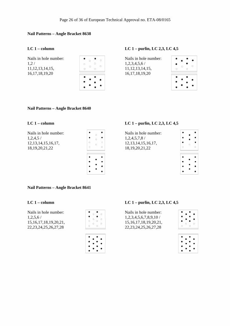
Nail Patterns – Angle Bracket 8638 LC 1 – column LC 1 – purlin, LC 2,3, LC 4,5 Nails in hole number: Nails in hole number: 1,2 / 1,2,3,4,5,6 / 11,12,13,14,15, 11,12,13,14,15, 16,17,18,19,20 16,17,18,19,20 Nail Patterns – Angle Bracket 8640 LC 1 – column LC 1 – purlin, LC 2,3, LC 4,5 Nails in hole number: Nails in hole number: 1,2,4,5 / 1,2,4,5,7,8 / 12,13,14,15,16,17, 12,13,14,15,16,17, 18,19,20,21,22 18,19,20,21,22 Nail Patterns – Angle Bracket 8641 LC 1 – column LC 1 – purlin, LC 2,3, LC 4,5 Nails in hole number: Nails in hole number: 1,2,5,6 / 1,2,3,4,5,6,7,8,9,10 / 15,16,17,18,19,20,21, 15,16,17,18,19,20,21, 22,23,24,25,26,27,28 22,23,24,25,26,27,28

Page 27 of 36 of European Technical Approval no. ETA-08/0165
Nail Patterns – Angle Bracket 8644 LC 1 – column LC 1 – purlin, LC 2,3, LC 4,5 Nails in hole number: Nails in hole number: 1,2,5,6,9,10 / 1,2,3,4,5,6,7, 19,20,21,22,23,24,25, 8,9,10,11,12,13,14 / 26,27,28,29,30,31, 19,20,21,22,23,24,25, 32,33,34,35,36 26,27,28,29,30,31, 32,33,34,35,36 Nail Patterns – Angle Bracket 8645 LC 1 – column LC 1 – purlin, LC 2,3, LC 4,5 Nails in hole number: Nails in hole number: 1,2,3,6,7,8 / 1,2,3,4,5,6,7, 21,22,28,29,30, 8,9,10,11,12,13,14, 33,34,35,38,39,40 15,16,17,18 / 19,20,21,22,23,24,25, 26,27,28,29,30,31, 32,33,34,35,36 Nail Patterns – Angle Bracket with rib 8622 LC 1 – column LC 1 – purlin, LC 2,3, LC 4,5 Nails in hole number: Nails in hole number: 1,2 / 1,2,6,7 / 10,11,14,15,17,18 10,11,14,15,17,18

Page 28 of 36 of European Technical Approval no. ETA-08/0165
Nail Patterns – Angle Bracket with rib 8628 LC 1 – column LC 1 – purlin, LC 2,3, LC 4,5 Nails in hole number: Nails in hole number: 1,2,6,7,11,12 / 1,2,4,5,6,7,8,9,11,12,13,14 / 17,18,22,23,26,27,31,32 17,18,22,23,26,27,31,32 Nail Patterns – Angle Bracket with rib 8629 LC 1 – column LC 1 – purlin, LC 2,3, LC 4,5 Nails in hole number: Nails in hole number: 1,2 / 1,2,4,5 / 9,10,14,15 9,10,14,15 Nail Patterns – Angle Bracket with rib 8632 LC 1 – column LC 1 – purlin, LC 2,3, LC 4,5 Nails in hole number: Nails in hole number: 1,2,10,11 / 1,2,6,9,12,13 / 14,15,18,21,25,26 14,15,18,21,25,26

Page 29 of 36 of European Technical Approval no. ETA-08/0165
Nail Patterns – Angle Bracket with rib 8633 LC 1 – column LC 1 – purlin, LC 2,3, LC 4,5 Nails in hole number: Nails in hole number: 2,3,12,13 / 1,4,6,9,12,13 / 16,17,23,24,27,28,29,30 16,17,18,19,22,25,27,30 Nail Patterns – Angle Bracket with rib 8654 LC 1 – column LC 1 – purlin, LC 2,3, LC 4,5 Nails in hole number: Nails in hole number: 1,2,3 / 1,3,6,7,12,13 / 14,15,16,19,20,21 14,15,16,19,20,21 Nail Patterns – Angle Bracket with rib 8655 LC 1 – column LC 1 – purlin, LC 2,3, LC 4,5 Nails in hole number: Nails in hole number: 1,2,4,5 / 1,2,4,5,7,8 / 9,10,12,13 9,10,12,13
Page 30 of 36 of European Technical Approval no. ETA-08/0165
Annex B
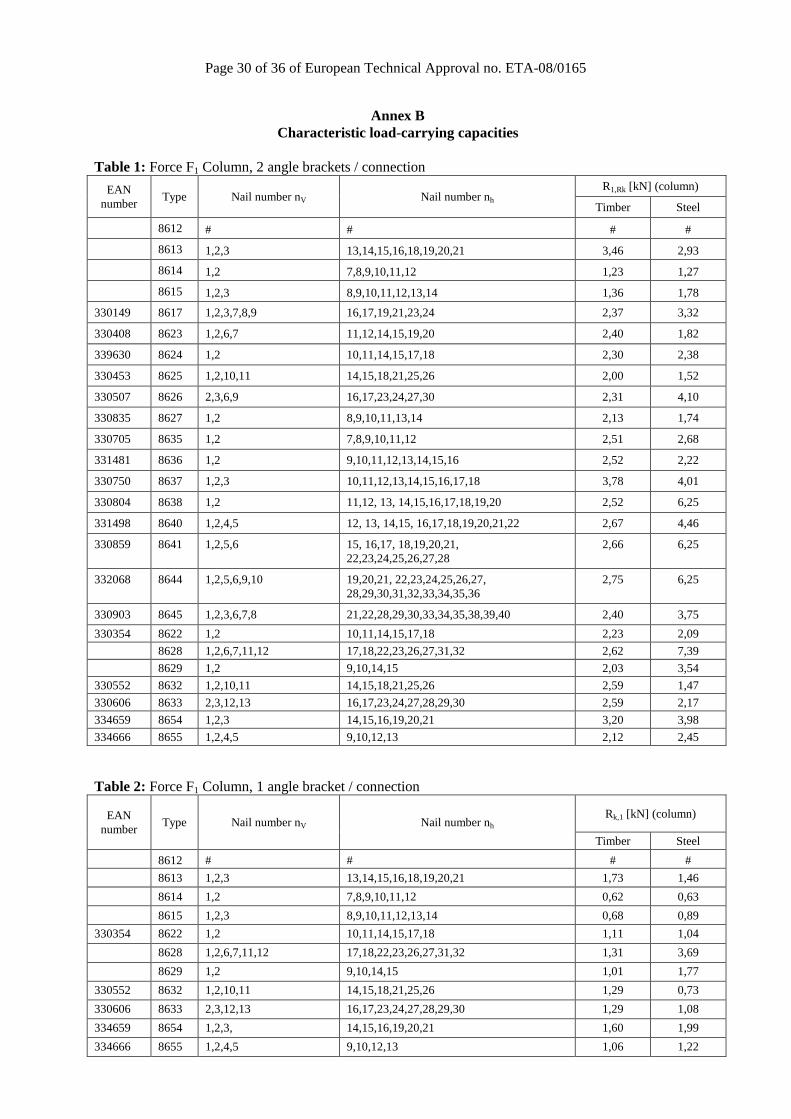
Characteristic load-carrying capacities Table 1: Force F1 Column, 2 angle brackets / connection
EAN number
Type Nail number nV Nail number nh R1,Rk [kN] (column)
Timber Steel
8612 # # # #
8613 1,2,3 13,14,15,16,18,19,20,21 3,46 2,93
8614 1,2 7,8,9,10,11,12 1,23 1,27
8615 1,2,3 8,9,10,11,12,13,14 1,36 1,78
330149 8617 1,2,3,7,8,9 16,17,19,21,23,24 2,37 3,32
330408 8623 1,2,6,7 11,12,14,15,19,20 2,40 1,82
339630 8624 1,2 10,11,14,15,17,18 2,30 2,38
330453 8625 1,2,10,11 14,15,18,21,25,26 2,00 1,52
330507 8626 2,3,6,9 16,17,23,24,27,30 2,31 4,10
330835 8627 1,2 8,9,10,11,13,14 2,13 1,74
330705 8635 1,2 7,8,9,10,11,12 2,51 2,68
331481 8636 1,2 9,10,11,12,13,14,15,16 2,52 2,22
330750 8637 1,2,3 10,11,12,13,14,15,16,17,18 3,78 4,01
330804 8638 1,2 11,12, 13, 14,15,16,17,18,19,20 2,52 6,25
331498 8640 1,2,4,5 12, 13, 14,15, 16,17,18,19,20,21,22 2,67 4,46
330859 8641 1,2,5,6 15, 16,17, 18,19,20,21, 22,23,24,25,26,27,28
2,66 6,25
332068 8644 1,2,5,6,9,10 19,20,21, 22,23,24,25,26,27, 28,29,30,31,32,33,34,35,36
2,75 6,25
330903 8645 1,2,3,6,7,8 21,22,28,29,30,33,34,35,38,39,40 2,40 3,75
330354 8622 1,2 10,11,14,15,17,18 2,23 2,09
8628 1,2,6,7,11,12 17,18,22,23,26,27,31,32 2,62 7,39
8629 1,2 9,10,14,15 2,03 3,54
330552 8632 1,2,10,11 14,15,18,21,25,26 2,59 1,47
330606 8633 2,3,12,13 16,17,23,24,27,28,29,30 2,59 2,17
334659 8654 1,2,3 14,15,16,19,20,21 3,20 3,98
334666 8655 1,2,4,5 9,10,12,13 2,12 2,45
Table 2: Force F1 Column, 1 angle bracket / connection
EAN number
Type Nail number nV Nail number nh Rk,1 [kN] (column)
Timber Steel
8612 # # # #
8613 1,2,3 13,14,15,16,18,19,20,21 1,73 1,46
8614 1,2 7,8,9,10,11,12 0,62 0,63
8615 1,2,3 8,9,10,11,12,13,14 0,68 0,89
330354 8622 1,2 10,11,14,15,17,18 1,11 1,04
8628 1,2,6,7,11,12 17,18,22,23,26,27,31,32 1,31 3,69
8629 1,2 9,10,14,15 1,01 1,77
330552 8632 1,2,10,11 14,15,18,21,25,26 1,29 0,73
330606 8633 2,3,12,13 16,17,23,24,27,28,29,30 1,29 1,08
334659 8654 1,2,3, 14,15,16,19,20,21 1,60 1,99
334666 8655 1,2,4,5 9,10,12,13 1,06 1,22

Page 31 of 36 of European Technical Approval no. ETA-08/0165
Table 3: Force F1 Purlin, 2 angle brackets / connection
EAN number
Type Nail number nV Nail number nh R1,Rk [kN] (column)
Timber Steel
8612 1,2,3,4,6 10,11,12 2,28 2,34
8613 1,2,3,4,5,7,8 13,14,15,16,18,19,20,21 3,46 2,93
8614 1,2,3,4,5 7,8,9,10,11,12 1,23 1,27
8615 1,2,3,4,5,6 8,9,10,11,12,13,14 1,36 1,78
330149 8617 1,3,5,6,7,9,11,12 16,17,19,21,23,24 2,37 3,32
330255 8620 1,2 5,6,7,8 1,15 1,52
330309 8621 4,5 8,9,13,14 1,92 1,24
330408 8623 1,2,6,7 11,12,16,17 2,37 1,82
339630 8624 1,2,4,5 10,11,14,15,17,18 2,30 2,38
330453 8625 1,2,6,9,12,13 14,15,22,24 2,00 1,52
330507 8626 1,4,7,8,14,15 16,17,23,24 2,31 4,09
330835 8627 1,2,4,5 8,9,10,11,13,14 2,13 1,74
330651 8634 1,2,3 7,8,9,10,11,12 3,27 4,01
330705 8635 1,2,3,4 7,8,9,10,11,12 2,51 2,67
331481 8636 1,2,3,4,5 9,10,11,12,13,14,15,16 2,52 2,22
330750 8637 1,2,3,4,5,6 10,11,12,13,14,15,16,17,18 3,77 4,01
330804 8638 1,2,3,4,5,6 11,12,13,14,15,16,17,18,19,20 2,52 6,25
331498 8640 1,2,3,4,5,6,7,8 12,13,14,15,16,17, 18,19,20,21,22
2,66 4,46
330859 8641 1,2,3,4,5,6,7,8,9,10 15,16,17,18,19,20,21,22,23,24,25,26,27,28
2,66 6,25
332068 8644 1,2,3,4,5,6,7,8,9,10, 11,12,13,14
19,20,21,22,23,24,25,26,27,28,29, 30,31,32,33,34,35,36
2,75 6,25
330903 8645 1,2,3,4,5,6,7,8,9,10,11,12,13,14,15,16,17,18
21,22,23,24,25,26,27,28,29,30,31, 32,33,34,35,36,37,38,39,40
2,40 3,75
330354 8622 1,2,6,7 10,11,14,15,17,18 2,23 2,09
8628 1,2,4,5,6,7,8,9,11,12,13,14 17,18,22,23,26,27,31,32 2,62 7,39
8629 1,2,4,5 9,10,14,15 2,03 3,54
330552 8632 1,2,6,9,12,13 14,15,18,21,25,26 2,59 1,46
330606 8633 1,4,6,9,12,13 16,17,18,19,22,25,27,30 2,59 2,17
334659 8654 1,3,6,7,12,13 14,15,16,19,20,21 3,20 3,98
334666 8655 1,2,4,5,7,8 9,10,12,13 2,11 2,45
Table 4: Force F1 Purlin, 1 angle bracket / connection EAN
number Type Nail number nV Nail number nh
R1,Rk [kN] (column)
Timber Steel
8612 1,2,3,4,6 10,11,12 1,14 1,17 8613 1,2,3,4,5,7,8 13,14,15,16,18,19,20,21 1,73 1,46
8614 1,2,3,4,5 7,8,9,10,11,12 0,62 0,63
8615 1,2,3,4,5,6 8,9,10,11,12,13,14 0,68 0,89
330354 8622 1,2,6,7 10,11,14,15,17,18 1,11 1,04
8628 1,2,4,5,6,7,8,9,11,12,13,14 17,18,22,23,26,27,31,32 1,31 3,69
8629 1,2,4,5 9,10,14,15 1,01 1,77
330552 8632 1,2,6,9,12,13 14,15,18,21,25,26 1,29 0,73
330606 8633 1,4,6,9,12,13 16,17,18,19,22,25,27,30 1,29 1,08
334659 8654 1,3,6,7,12,13 14,15,16,19,20,21 1,60 1,99
334666 8655 1,2,4,5,7,8 9,10,12,13 1,05 1,22

Page 32 of 36 of European Technical Approval no. ETA-08/0165
Table 5: Forces F2,3, 2 angle brackets / connection
EAN number
Type Nail number nV Nail number nh R2,3,Rk [kN]
Timber
8612 1,2,3,4,6 10,11,12 4,40
8613 1,2,3,4,5,7,8 13,14,15,16,18,19,20,21 7,46
8614 1,2,3,4,5 7,8,9,10,11,12 4,54
8615 1,2,3,4,5,6 8,9,10,11,12,13,14 4,97
330149 8617 1,3,5,6,7,9,11,12 16,17,19,21,23,24 6,30
330255 8620 1,2 5,6,7,8 2,22
330309 8621 4,5 8,9,13,14 3,11
330408 8623 1,2,6,7 11,12,16,17 3,39
339630 8624 1,2,4,5 10,11,14,15,17,18 4,73
330453 8625 1,2,6,9,12,13 14,15,22,24 4,20
330507 8626 1,4,7,8,14,15 16,17,23,24 1,99
330835 8627 1,2,4,5 8,9,10,11,13,14 3,06
330651 8634 1,2,3 7,8,9,10,11,12 5,34
330705 8635 1,2,3,4 7,8,9,10,11,12 2,85
331481 8636 1,2,3,4,5 9,10,11,12,13,14,15,16 5,86
330750 8637 1,2,3,4,5,6 10,11,12,13,14,15,16,17,18 9,72
330804 8638 1,2,3,4,5,6 11,12,13,14,15,16,17,18,19,20 7,72
331498 8640 1,2,3,4,5,6,7,8 12,13,14,15,16,17,18,19,20,21,22 7,57
330859 8641 1,2,3,4,5,6,7,8,9,10 15,16,17,18,19,20,21,22,23,24,25,26,27,28 10,2
332068 8644 1,2,3,4,5,6,7,8,9,10, 11,12,13,14
19,20,21,22,23,24,25,26,27,28,29,30,31,32,33,34, 35,36 12,2
330903 8645 1,2,3,4,5,6,7,8,9,10,11,12,13,14,15,16, 17,18
21,22,23,24,25,26,27,28,29,30,31,32,33,34,35,36 37,38,39,40
16,0
330354 8622 1,2,6,7 10,11,14,15,17,18 5,23
8628 1,2,4,5,6,7,8,9,11,12,13,14 17,18,22,23,26,27,31,32 8,37
8629 1,2,4,5 9,10,14,15 5,71
330552 8632 1,2,6,9,12,13 14,15,18,21,25,26 4,83
330606 8633 1,4,6,9,12,13 16,17,18,19,22,25,27,30 6,34
334659 8654 1,3,6,7,12,13 14,15,16,19,20,21 8,03
334666 8655 1,2,4,5,7,8 9,10,12,13 3,09
Table 6: Forces F2,3, 1 angle bracket / connection EAN
number Type Nail number nV Nail number nh
R2,3,Rk [kN]
Timber
8612 1,2,3,4,6 10,11,12 2,20 8613 1,2,3,4,5,7,8 13,14,15,16,18,19,20,21 3,73
8614 1,2,3,4,5 7,8,9,10,11,12 2,27
8615 1,2,3,4,5,6 8,9,10,11,12,13,14 2,49
330354 8622 1,2,6,7 10,11,14,15,17,18 2,61
8628 1,2,4,5,6,7,8,9,11,12,13,14
17,18,22,23,26,27,31,32 4,19
8629 1,2,4,5 9,10,14,15 2,85
330552 8632 1,2,6,9,12,13 14,15,18,21,25,26 2,41
330606 8633 1,4,6,9,12,13 16,17,18,19,22,25,27,30 3,17
334659 8654 1,3,6,7,12,13 14,15,16,19,20,21 4,01
334666 8655 1,2,4,5,7,8 9,10,12,13 1,54

Page 33 of 36 of European Technical Approval no. ETA-08/0165
Table 7: Basic Forces F4,5, 2 angle brackets / connection
EAN number
Type Nail number nV Nail number nh R4,5,Rk [kN]
Timber Steel
8612 1,2,3,4,6 10,11,12 5,64 3,88 8613 1,2,3,4,5,7,8 13,14,15,16,18,19,20,21 6,44 3,82
8614 1,2,3,4,5 7,8,9,10,11,12 5,98 1,92
8615 1,2,3,4,5,6 8,9,10,11,12,13,14 6,02 1,90
330149 8617 1,3,5,6,7,9,11,12 16,17,19,21,23,24 6,38 3,82
330255 8620 1,2 5,6,7,8 3,85 1,45
330309 8621 4,5 8,9,13,14 5,36 4,05
330408 8623 1,2,6,7 11,12,16,17 5,42 4,10
339630 8624 1,2,4,5 10,11,14,15,17,18 4,73 3,87
330453 8625 1,2,6,9,12,13 14,15,22,24 5,15 4,28
330507 8626 1,4,7,8,14,15 16,17,23,24 10,3 11,2
330835 8627 1,2,4,5 8,9,10,11,13,14 5,28 2,80
330651 8634 1,2,3 7,8,9,10,11,12 8,76 3,44
330705 8635 1,2,3,4 7,8,9,10,11,12 4,84 2,52
331481 8636 1,2,3,4,5 9,10,11,12,13,14,15,16 5,90 2,29
330750 8637 1,2,3,4,5,6 10,11,12,13,14,15,16,17,18 7,26 3,77
330804 8638 1,2,3,4,5,6 11,12,13, 14,15,16,17,18,19,20 7,81 4,67
331498 8640 1,2,3,4,5,6,7,8 12,13,14,15,16,17,18,19,20,21,22 7,18 3,04
330859 8641 1,2,3,4,5,6,7,8,9,10 15,16,17,18,19,20,21,22,23,24,25,26,27,28
8,75 4,98
332068 8644 1,2,3,4,5,6,7,8,9,10, 11,12,13,14
19,20,21,22,23,24,25,26,27,28,29, 30,31,32,33,34,35,36
9,66 4,92
330903 8645 1,2,3,4,5,6,7,8,9,10, 11,12,13,14,15,16,17,18
21,22,23,24,25,26,27,28,29,30,31, 32,33,34,35,36,37,38,39,40
13,1 6,28
330354 8622 1,2,6,7 10,11,14,15,17,18 5,15 3,88
8628 1,2,4,5,6,7,8,9,11,12,13,14 17,18,22,23,26,27,31,32 13,8 6,85
8629 1,2,4,5 9,10,14,15 5,96 3,43
330552 8632 1,2,6,9,12,13 14,15,18,21,25,26 6,11 8,11
330606 8633 1,4,6,9,12,13 16,17,18,19,22,25,27,30 6,70 9,81
334659 8654 1,3,6,7,12,13 14,15,16,19,20,21 5,39 7,29
334666 8655 1,2,4,5,7,8 9,10,12,13 4,82 4,34
Table 8: Basic Forces F4, 1 angle bracket / connection
EAN number
Type Nail number nV Nail number nh R4,Rk [kN]
Timber Steel
330354 8622 1,2,6,7 10,11,14,15,17,18 7,53 2,85
335724 8628 1,2,4,5,6,7,8,9,11,12,13,14 17,18,22,23,26,27,31,32 12,8 5,06
335717 8629 1,2,4,5 9,10,14,15 6,48 3,07
330552 8632 1,2,6,9,12,13 14,15,18,21,25,26 7,38 5,62
330606 8633 1,4,6,9,12,13 16,17,18,19,22,25,27,30 10,0 6,87
334659 8654 1,3,6,7,12,13 14,15,16,19,20,21 4,92 4,94
334666 8655 1,2,4,5,7,8 9,10,12,13 4,84 3,97

Page 34 of 36 of European Technical Approval no. ETA-08/0165
Table 9: Basic Forces F5, 1 angle bracket / connection
EAN number
Type Nail number nV Nail number nh R4,Rk [kN]
Timber Steel
330354 8622 1,2,6,7 10,11,14,15,17,18 1,34 1,17
335724 8628 1,2,4,5,6,7,8,9,11,12,13,14 17,18,22,23,26,27,31,32 2,09 2,08
335717 8629 - - - -
330552 8632 1,2,6,9,12,13 14,15,18,21,25,26 1,81 2,50
330606 8633 1,4,6,9,12,13 16,17,18,19,22,25,27,30 1,72 3,09
334659 8654 1,3,6,7,12,13 14,15,16,19,20,21 1,52 2,29
334666 8655 1,2,4,5,7,8 9,10,12,13 1,47 1,41

Page 35 of 36 of European Technical Approval no. ETA-08/0165
Definitions of forces, their directions and eccentricity Forces - Beam to beam connection
Fastener specification Holes are marked with numbers referring to the nailing pattern in Annex A. Double angle brackets per connection The angle brackets must be placed at each side opposite each other, symmetric to the component axis. Acting forces F1 Lifting force acting along the central axis of the joint. F2 and F3 Lateral force acting in the joint between the component 2 and component 1 in the
component 2 direction F4 and F5 Lateral force acting in the component 1 direction along the central axis of the joint. If
the load is applied with an eccentricity e, a design for combined loading is required. Single angle bracket per connection Acting forces F1 Lifting force acting in the central axis of the angle bracket. The component 2 shall be
prevented from rotation. If the component 2 is prevented from rotation the load-carrying capacity will be half of a connection with double angle brackets.
F2 and F3 Lateral force acting in the joint between the component 2 and the component 1 in the component 2 direction. The component 2 shall be prevented from rotation. If the component 2 is prevented from rotation the load-carrying capacity will be half of a connection with double angle brackets.
F4 and F5 Lateral force acting in the component 1 direction in the height of the top edge of component 2. F4 is the lateral force towards the angle bracket; F5 is the lateral force away from the angle bracket. Only the characteristic load-carrying capacities for angle brackets with ribs are given.
Component 1 Component 1
b
F5
F1
e
F1
F2 F3
F4 Component 2
Page 36 of 36 of European Technical Approval no. ETA-08/0165
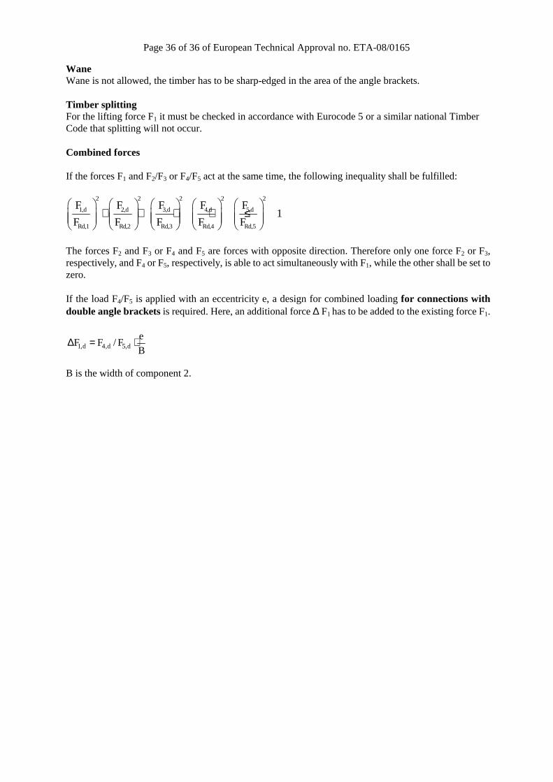
Wane Wane is not allowed, the timber has to be sharp-edged in the area of the angle brackets. Timber splitting For the lifting force F1 it must be checked in accordance with Eurocode 5 or a similar national Timber Code that splitting will not occur. Combined forces If the forces F1 and F2/F3 or F4/F5 act at the same time, the following inequality shall be fulfilled:
2 2 2 2 2
1,d 2,d 3,d 4,d 5,d
Rd,1 Rd,2 Rd,3 Rd,4 Rd,5
F F F F F1
F F F F F
+ + + + ≤
The forces F2 and F3 or F4 and F5 are forces with opposite direction. Therefore only one force F2 or F3, respectively, and F4 or F5, respectively, is able to act simultaneously with F1, while the other shall be set to zero. If the load F4/F5 is applied with an eccentricity e, a design for combined loading for connections with double angle brackets is required. Here, an additional force ∆ F1 has to be added to the existing force F1.
1,d 4,d 5,de
F F / FB
∆ = ⋅
B is the width of component 2.