Embed Size (px)
Citation preview

EUROPEAN ISSUE
2
Specifications
UPPER REVOLVING FRAME:All-welded, precision machined, robustconstruction. A machined surface providedfor mounting load hoist and boom hoistassemblies, and mounting itself on turntablebearing.
TURNTABLE BEARING WITH INTERNAL SWING GEAR:Heavy duty, single shear ball type; inner raceof turntable bearing with integral, internalswing (ring) gear bolted to carbody frame,and outer race of turntable bearing bolted toupper revolving frame.
CONTROL SYSTEM:System contains two sets of triplicate tandemvalves which direct oil to various machinefunction and are actuated by control levers viaremote controlled hydraulic servo for allmotions. Working speeds can be preciselycontrolled by motorcycle type throttle andpilot-operated arm chair single axis controllevers in cooperation with “SC” controller thatvaries engine rpm and hyd. pump dischargesimultaneously, or varies just hyd. pumpdischarge while keeping engine rpm. Systemalso takes unique EEPSA (Electrical EnginePump Sensing Analyzer) to maximizes drumhorsepower, and reduces horsepower losswith eliminating the possibility of engine stall.
Pump control system — By “SC” controller thatprovides two modes of engine-pump control.MODE I:The SC Controller is normally programmed tovary the engine speed and pump dischargesimultaneously. Simply twisting the gripadvances the engine to maximum speed andthe hydraulic pumps to maximum flow at thesame time. This mode is suitable to precisioncrane work.MODE II:By activating a switch, it is able to vary justthe pump discharge by means of the gripthrottle, while keeping engine speed fixed.Mode II is convenient for operations such aslifting magnet and bucket work, where theengine is normally run at full throttle.
HYDRAULIC SYSTEM:System provided with three variabledisplacement axial piston pumps and onefixed displacement duplicate tandem gearpump for both independent and combinedoperations of all functions. Gear pump alsoused for system valves and cylinder controls.
Main/aux. crane hoist motors — Variable dis-placement axial piston motor withcounterbalance valve and spring-applied/hydraulically released multiple wet-disc typeautomatic brake.
Boom hoist motor — Two; axial piston type withcounterbalance valve and spring-applied/hydraulically released multiple wet-disc type automatic brake.
Luffing jib hoist drum motor — Optional extra; axialpiston type with counterbalance valve andspring-applied/hydraulically released multiplewet-disc type automatic brake; required whenmachine is operated with luffing towercraneattachment.
Swing motor — Two; axial piston type with spring-applied/hydraulically released multiple wet-disc type manually controlled brake.
Travel motors — Shoe-in design; axial piston motor
SuperstructureHITACHI SUMITOMO
with brake valve and spring-applied/hydrauli-cally released multiple wet-disc type automaticbrake.
Oil cooler — Located at right-rear of machinery roomas separated from engine radiator togetherwith an independent autocooling fan for bettercooling efficiency and heat balance.
Independent hyd. circuits — Available in betweenhydraulic circuits of P1 main pump and frontmain drum winch motor, and between P2main pump and rear main drum winch motor.
Hydraulic oil reservoir — 410 liters capacity.
LOAD HOIST ASSEMBLY:Front and rear main operating drums drivenby independent hydraulic motor of bi-directional, variable displacement axial pistonmotor through 2-stage planetary reductiongear units powering the rope drum in eitherdirection for hoisting and lowering load. Eachof drum sized in same dimension.
Brakes — Spring-applied, power hadraulicallyreleased multiple wet-dise type automaticbrake; provided within hyd. moter;
Clutches — Optional extra; internal expanding, self-adjusting, mono-band design with non-asbestos l ining; spring-applied, powerhydraulically released. Available for a truegravity free-fall operation in functionalcooperation with optional “ externalcontracting band type brakes” .
External contracting band type brakes — Optionalextra; required together with optional“ clutches” for a true gravity free-falloperation. Instead of standardized autmaticbrake, an external contracting band typebrake with 1,270mm dia. by 170mm widebrake drum with non-asbestos lining operatedby power hydraulically assisted foot pedalwith locking latch is designed. Two brakemodes are available; for crane operation,automatic brake, spring-applied, powerhydraulically released is applied when controllever is in neutral position, and for bucketoperation, free-fail is available in the abovecontrol lever position.
Drums — One piece, parallel grooved lagging withlocking ratchet wheel cast integral; mountedon drum shaft through anti-friction bearings.
Drum locks — Power hydraulically operatedautomatic pawl as std. while electricallycontrolled pawl is designed i/o automatic in acase of two main operating drums withoptional free-fall function.
Drum rollers — Optional extra; available for rightcable winding onto drums.
BOOM HOIST ASSEMBLY:Twin-drum design; driven by two bi-directional, axial piston hydraulic motorthrough 2 sets of 2-stage planetary reductiongear unit powering the rope drum in eitherdirection for hoisting and lowering boom.
Brake — Spring-applied, power hydraulically releasedmultiple wet-disc type automatic brake.
Drum — One piece, twin-designed parallel grooved withlocking ratchet wheel cast integral; bolted toplanetary reduction gear unit outer cased of hydmoters.
Drum lock — Power hydraulically operated automaticpawl.
LUFFING JIB HOIST DRUM WINCH MECHANISM:Optional extra; driven by bi-directional, axialpiston hydraulic motor through 2-stageplanetary reduction gear unit powering therope drum in either direction for hoisting andlowering tower jib; required when machine isoperated with luffing towercrane attachment.
This third drum winch mechanism mountedwithin tower boom bottom section for moresafety and easy erection work of luffingtowercrane attachment.
Brake — Spring-applied, power hydraulically releasedmultiple wet-disc type automatic brake;provided within hydraulic motor.
Drum — One piece, parallel grooved lagging withlocking ratchet wheel cast integral; bolted toplanetary reduction gear unit outer case ofhyd. motor.
Drum lock — Power hydraulically operated automaticpawl.
SWING:Driven by two units of bi-directional, axialpiston hydraulic motors through 2 sets ofplanetary reduction gear unit powering swingpinion. Swing pinion meshes with internalteeth of swing (ring) gear of turntable bearinginner race.
Brakes — Spring-applied, power hydraulicallyreleased multiple wet-disc type; provided oneach of hydraulic motor.
Swing speed control — Max. swing speed can betuned according to arbitrary value that iselectrically controlled by dialing, and thenvaries pump discharge.
Lock — Mechanically operated drop pin.Speed — 1.7min.–1 <1.7rpm>
GANTRY:A-frame type; raised and lowered by powerhydraulic cylinders.
OPERATOR’S CAB:Swing-away design to set a 3.19-meter overallwidth of superstucture for a good transport;940mm wide; acoustically treated, all newstamped, automotive type, full-vision, cushionrubber mounted, well-venti lated, ful lcompartment, roomy operator’s cab with largecurved front window; provided with anarrangement of “SC” control/swing lever,sunvisor, sunshade, rear-view mirrors,intermittent dual window shield wipers withwasher on both front and roof windows, androll-down window on sliding door.
Instrument panel — Contains engine monitoringlamps, display panel of SML-10 Load MomentLimiter, and other necessary controllers andswitches.
Operator’s seat — Full adjustable reclining seat.Air-conditioner — Optional extra;built-in type full air-
conditioning.Heater — Optional extra;hot water type.Anemometer — Analogue type; provided with a
function of warning buzzer when wind velocityexceeds 10 m/s.
Stone guard — Optional extra; stainless steel-make.This is available for operator’s cab protectionfrom outside obstacles.
AM/FM radio — Provided as std. with clock.Fire extinguisher — Optional extra; powder type with
1kg capacity.
MACHINERY CAB:Equipped with hinged doors on both sides formachinery access and inspection; tape-typenon-skid material applied to the roof.
CATWALKS:Optional extra; hitched in place along bothsides of machinery cab.
3
HYDRAULIC TAGLINE WINDER:Optional extra; provided in front of upperrevolving frame, and this is available forpreventing a shake of suspended load likeclamshell bucket by an 10mm dia. tug cablewith light force.
COUNTERWEIGHTS:Weighs 93.7ton consisting of a 12.3ton steelbase plate, 6ton steel plate and 8 blocks ofcast, removable, corner-rounded design whichconsist of “A” (10,900kg), “B” (10,900kg), “C”(10,800kg), “D” (10,800kg), “E” (8,500kg), “F”(8,100kg), “G” (7,900kg) and “H” (7,500kg).Note: A 6ton steel plate must be deducted
when boom length does not exceed21.35m in the case of l iftcraneapplication.
ELECTRICAL SYSTEM:24-volt negative ground system; provided withtwo maintenance free 12-volt batteries.
LIGHTING SYSTEM:Includes following lights.• Two 70 W working lights;• One 10 W interior cab light.
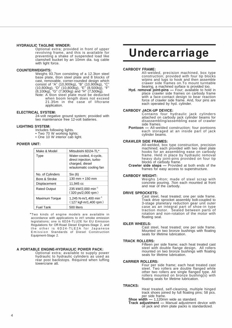
POWER UNIT:
*Two kinds of engine models are available inaccordance with applications to int'l smoke emissionlegislations; one is 6D24-TLU2E for EU EmissionRegulations for Off-Road Diesel Engines-Stage 2, andt h e o t h e r i s 6 D 2 4 - T L E 2 A f o r J a p a n e s eE m i s s i o n Standards of Diesel ConstructionEquipment-Stage 2.
A PORTABLE ENGINE-HYDRAULIC POWER PACK:Optional extra; available to supply powerhydraulic to hydraulic cylinders as used asrear post backstops. Required when luffingtowercrane att.
CARBODY FRAME:All-welded, precision machined, box typeconstruction; provided with four tip blocksw/pins and lugs to hook and then assemblecrawer side frames on.To mount turntablebearing, a machined surface is provided too.
Hyd. removal joint-pins — Four; available to hold inplace crawler side frames on carbody framewith a face-contact design to bear reactionforce of crawler side frame. And, four pins areeach operated by hyd. cylinder.
CARBODY JACK-UP DEVICE:Contains four hydraulic jack cylindersattached on carbody jack cylinder beams fordisassembling/assembling ease of crawlerside frames.
Pontoon — All-welded construction; four pontoonseach storaged at an inside part of jackcylinder beams.
CRAWLER SIDE FRAMES:All-welded, box type construction, precisionmachined; each provided with two steel platehooks for an assembling ease on carbodyframe. Held in place by hydraulic removalheavy duty joint-pins provided on four tipblocks of carbody frame.
Crawler side steps — Provided at both ends of theframes for easy access to superstructure.
CARBODY WEIGHT:Weighs 14ton; made of steel scrap withconcrete pouring. 7ton each mounted at frontand rear of the carbody.
DRIVE SPROCKETS:Cast steel, heat treated; one per side frame.Track drive sprocket assembly bolt-coupled to3-stage planetary reduction gear unit outercase as an integral part of shoe-in typetraction motor. Sealed between parts ofrotation and non-rotation of the motor withfloating seal.
IDLER WHEELS:Cast steel, heat treated; one per side frame.Mounted on two bronze bushings with floatingseals for lifetime lubrication.
TRACK ROLLERS:Fifteen per side frame; each heat treated caststeel with double flange design. All rollersmounted on two bronze bushings with floatingseals for lifetime lubrication.
CARRIER ROLLERS:Four per side frame; each heat treated caststeel. Two rollers are double flanged whileother two rollers are single flanged type. Allrollers mounted on bronze bushing(s) withfloating seals for lifetime lubrication.
TRACKS:Heat treated, self-cleaning, multiple hingedtrack shoes joined by full floating pins; 58 pcs.per side frame.
Shoe width — 1,120mm wide as standard. Track adjustment — Manual adjustment device with
oil jack and shim plate packs is standardized.
4
Make & Model
Type�
�
No. of Cylinders
Bore & Stroke
Displacement
Rated Output
Maximum Torque
Fuel Tank
Mitsubishi 6D24–TL*
Water-cooled, 4-cycle,�direct injection, turbo-charged, diesel w/automatic cooling fan
Six (6)
130 mm × 150 mm
11,945 cc
235 kW/2,000 min–1�
〈320 ps/2,000 rpm〉
1,245 N·m/1,400 min–1�
〈127 kgf-m/1,400 rpm〉 500 liters
Undercarriage
Automatic track tension adjusting device —Optional extra; available instead of std. trackadjustment to always keep track tension atoptimum level by means of power hyd.cylinder thru idler wheel actuated by powerhydraulic supplied from superstructure.
TRAVEL AND STEERING:A bi-directional, shoe-in type axial pistonhydraulic motor bolt-couples drive sprocket thru3-stage planetary reduction gear unit outer caseat each crawler side frame end for travel andsteer. Straight-line travel (forward or reverse),pivot or differential turns, and counter-rotation forspin turns are available.
Brake — Spring-applied, hydraulically releasedmultiple wet-disc type automatic brake; locatedwithin hydraulic motor. Brakes automaticallyset when travel levers are in neutral or whenengine is shut down.
Travel speed — 1.2/0.8km/hr. (based on flat, leveland firm supporting surface, and under theconditions that no load must be applied andfront-end att. must be 15.25m basic boomonly).
Gradeability — 30% (17°) permissible based on basicmachine without front-end attachment.
SML-10 LOAD MOMENT LIMITER:This is a fully computerized total safe operationcontrol system, and automatic over-loadpreventing system as standard equipment. The SML-10 meets EN Standards.
Construction (standard version) — Comprises (1)load detecting device, (2) boom angledetector, and (3) display panel withcomputerized Micro processing Unit (M.P.U).
Functions — This system functions that if a liftingload reaches a 90% of the rated one specifiedin the crane capacity chart, an annunciatingpre-warning is given; if i t is an 100%, awarning is given by red lamp, andannunciating warning, and all peri l sidemotions are automatically stopped. Themachine, however, can be operated in safetyside motions.
Display panel design — The SML-10 is designed tobe able to input the operating conditions/data bysetting keys on LCD 1, and to indicate thepresent lifting conditions/data like “lifting load”“rated load”, “working radius” “boom angle”, andso forth on LCD 2 thru LCD 5. Also, the LCD 1indicates “engine rpm”, “load ratio” and “liftingheight (opt.)”. In addition, the LCD 1 indicatesletter messages when the machine becomesabnormal.
DRUM ROPE OVER-PAYOUT PREVENTING DEVICE:Available on both front and rear main drums,and functions to automatically stop drumrotation when no. of rope winding at 1st layerbecomes three(3).
NON FREE-FALL OPERATION SWITCH:Optional extra; this is standardized when opt.free-fall function on two main drums isdesigned, and available for keeping non free-fall operation during operation when it isnecessary. Provided with key for switch on–offcontrol.
HOOK OVER-HOIST LIMITING DEVICE:Limit switch type. Available to prevent hookover-hoisting with functions of automatic drumbraking with hydraulic lock, and warnings byred lamp and annunciating alarm.
BOOM OVER-HOIST AND -LOWERING LIMITING DEVICE:Available in two kinds of devices; one is limitswitch located on a part of boom foot forpreventing boom over-hoisting, and the otheris the safety function of the SML-10 availableto automatically prevent boom over-hoistingand -lowering with the functions of automaticdrum braking with hydraulic lock, andwarnings by red lamp and annunciating alarm.Further boom protection from rapid boomover-hoist by hook over-hoist motion undermal-function of hook over-hoist limiting deviceis available as one of functions of the SML-10.
BOOM BACKSTOPS:Dual; telescopic design with spring buffers.
DUAL BOOM OVER-HOIST LIMITING DEVICE:Additional l imit switch located on boombackstops; this is as a further safety devicefor redundant boom protection.
SWING LOCK:Mechanically operated drop pin; available tofirmly lock superstructure in four positions offacing front or rear or left or right to undercarriage.
DRUM LOCKS:Power hydraulically operated pawl lock isavailable on front, rear and boom hoist drumwith an automatic locking device as std. whileelectrically controlled pawl locks is designed onfront and rear main drums i/o automatic incase that free-fall function is required.
BOOM ANGLE INDICATOR:Pendulum type; mounted on right-hand side ofbottom section of crane main boom.
HOOK LATCH:Provided on every kinds of hook to preventout of place of cable from hook.
LEVEL GAUGE:Bubble type; located on operator’s cab floorand a part of undercarriage.
LEVER LOCKS:Provided on all control levers (except swinglever) to lock levers in neutral.
5
Safety Devices

SWING ALARM:This is by buzzer, and flasher lamps locatedon both sides of machinery cab.
WARNING ALARMS:This is one of functions of the SML-10;provided with some kinds of different audiblealarms to let operator know the operationlimit.
SPEED SLOWDOWN DEVICE:This is for speed slowdown of hoisting andlowering motions of crane main boom whichare available just before automatic stopping toprevent a shock.
SWING BRAKE LAMP:Provided on operator’s cab instrument panel;this is available to confirm whether or notswing brake is applied.
SIGNAL HORN:Available as warning just before every kindsof motions from operator.
FOOL PROOF SHUT-OFF SYSTEM:Located in the cab exit; this is available toautomatically deactivate and lock hydraulicsystem.
TRAVEL ALARM:Buzzer warns when travel motion is initiated.
ENGINE MONITORING LAMPS:Available for checking engine operatingconditions like battery charge, engine oilpressure, radiator coolant level, oil f i l terclogging, air f i l ter clogging, and batteryelectrolyte amount.
EMERGENCY MACHINE STOP BUTTONS:Two; each located nearby front main andboom hoist drums. Available when it isnecessary to stop all machine motion.
REAR VIEW MIRRORS:Two each provided on front-left and -rightcorners of superstructure.
THREE COLOR PERCENTAGE INDICATOR:Optional extra; this is with three colours ofGreen, Yellow and Red. Each colourindicates the load percentage to ratedcapacity; Green shows less than 90% assafety, Yellow shows 90 to 99% as marginal,and Red shows over 100% as over-loading.As further function, Red lamp comes onautomatically when operator cuts off safetydevice switch absent-mindedly.
LIFTING HEIGHT METER:Optional extra; available to indicate liftingheight above ground or depth below groundon display “LCD 1” of SML-10 Load MomentLimiter display panel. Also, hook hoistingspeed slowdown function is available justbefore automatic stopping at a desired heightunder hook heightsetting before operation.
MICROPHONE & LOUD-SPEAKER:Optional extra; this is for operator’sconvenience for loud speaking.
DRUM LIGHT & MIRROR:Optional extra; these are available forchecking rope winding onto front and/or reardrum(s).
AUX. CRANE HOOK OVER-HOIST LIMITING DEVICE:Optional extra; this is available for auxiliarycrane hoist with optional aux. short jib and/orfly jib. Performs the same function as that of“Hook over-hoist limiting device” mentionedbefore.
In addition to the above, following safety devices arestandard for luffing towercrane attachment.
LUFFING JIB ANGLE DETECTOR:This is one of key safety device in a case ofluffing towercrane attachment.
LUFFING TOWERCRANE LOAD DETECTOR:This is also important safety device whenluffing towercrane attachment is required.
LUFFING JIB OVER-HOIST AND -LOWERING LIMITINGDEVICE:
Performs all the same function as that of“Boom over-hoist and -lowering l imit ingdevice” stated before.
LUFFING JIB HOOK OVER-HOIST LIMITING DEVICE:Performs the same function as that of “Hookover-hoist lifting device” described before.
LUFFING TOWERCRANE ATT. SELF-ERECTIONMODE:
This is an internal, integral mode as one ofkey function of the SML-10 for safe self-erection and -laying down of luff ingtowercrane attachment without fail.
LUFFING JIB BACKSTOPS:Dual; telescopic design with spring buffers.
DUAL LUFFING JIB OVER-HOIST LIMITING DEVICE:Additional limit switch located on tower jibbackstops; this is as a further safety devicefor redundant tower jib protection.
LUFFING JIB HOIST DRUM LOCK:Provided with automatic pawl-locking devicelike other drum pawl-locking.
REAR POST BACKSTOPS:Two power hydraulic cylinders are designedto easily set rear post position as necessarywhen assembling front post and luffing jib;power hydraulic is supplied to these cylindersby a portable engine-hydraulic power pack.
6
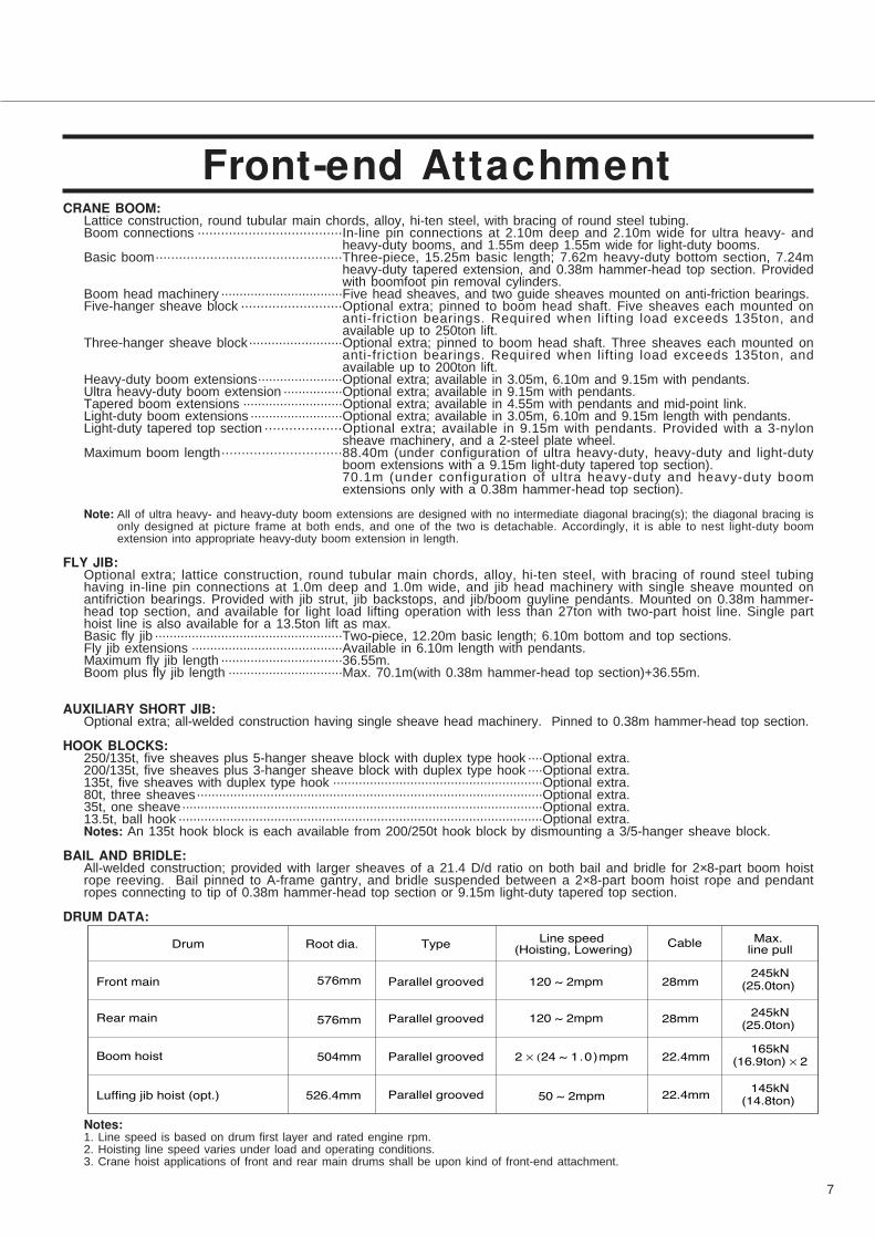
CRANE BOOM:Lattice construction, round tubular main chords, alloy, hi-ten steel, with bracing of round steel tubing.Boom connections .....................................In-line pin connections at 2.10m deep and 2.10m wide for ultra heavy- and
heavy-duty booms, and 1.55m deep 1.55m wide for light-duty booms.Basic boom................................................Three-piece, 15.25m basic length; 7.62m heavy-duty bottom section, 7.24m
heavy-duty tapered extension, and 0.38m hammer-head top section. Providedwith boomfoot pin removal cylinders.
Boom head machinery .................................Five head sheaves, and two guide sheaves mounted on anti-friction bearings.Five-hanger sheave block ..........................Optional extra; pinned to boom head shaft. Five sheaves each mounted on
anti-friction bearings. Required when lifting load exceeds 135ton, andavailable up to 250ton lift.
Three-hanger sheave block.........................Optional extra; pinned to boom head shaft. Three sheaves each mounted onanti-friction bearings. Required when lifting load exceeds 135ton, andavailable up to 200ton lift.
Heavy-duty boom extensions.......................Optional extra; available in 3.05m, 6.10m and 9.15m with pendants.Ultra heavy-duty boom extension ................Optional extra; available in 9.15m with pendants.Tapered boom extensions ...........................Optional extra; available in 4.55m with pendants and mid-point link.Light-duty boom extensions .........................Optional extra; available in 3.05m, 6.10m and 9.15m length with pendants.Light-duty tapered top section ...................Optional extra; available in 9.15m with pendants. Provided with a 3-nylon
sheave machinery, and a 2-steel plate wheel.Maximum boom length..............................88.40m (under configuration of ultra heavy-duty, heavy-duty and light-duty
boom extensions with a 9.15m light-duty tapered top section).70.1m (under configuration of ultra heavy-duty and heavy-duty boomextensions only with a 0.38m hammer-head top section).
Note: All of ultra heavy- and heavy-duty boom extensions are designed with no intermediate diagonal bracing(s); the diagonal bracing isonly designed at picture frame at both ends, and one of the two is detachable. Accordingly, it is able to nest light-duty boomextension into appropriate heavy-duty boom extension in length.
FLY JIB:Optional extra; lattice construction, round tubular main chords, alloy, hi-ten steel, with bracing of round steel tubinghaving in-line pin connections at 1.0m deep and 1.0m wide, and jib head machinery with single sheave mounted onantifriction bearings. Provided with jib strut, jib backstops, and jib/boom guyline pendants. Mounted on 0.38m hammer-head top section, and available for light load lifting operation with less than 27ton with two-part hoist line. Single parthoist line is also available for a 13.5ton lift as max.Basic fly jib ...................................................Two-piece, 12.20m basic length; 6.10m bottom and top sections.Fly jib extensions .........................................Available in 6.10m length with pendants.Maximum fly jib length .................................36.55m.Boom plus fly jib length ...............................Max. 70.1m(with 0.38m hammer-head top section)+36.55m.
AUXILIARY SHORT JIB:Optional extra; all-welded construction having single sheave head machinery. Pinned to 0.38m hammer-head top section.
HOOK BLOCKS:250/135t, five sheaves plus 5-hanger sheave block with duplex type hook ....Optional extra.200/135t, five sheaves plus 3-hanger sheave block with duplex type hook ....Optional extra.135t, five sheaves with duplex type hook .........................................................Optional extra.80t, three sheaves..............................................................................................Optional extra.35t, one sheave..................................................................................................Optional extra.13.5t, ball hook ...................................................................................................Optional extra.Notes: An 135t hook block is each available from 200/250t hook block by dismounting a 3/5-hanger sheave block.
BAIL AND BRIDLE:All-welded construction; provided with larger sheaves of a 21.4 D/d ratio on both bail and bridle for 2×8-part boom hoistrope reeving. Bail pinned to A-frame gantry, and bridle suspended between a 2×8-part boom hoist rope and pendantropes connecting to tip of 0.38m hammer-head top section or 9.15m light-duty tapered top section.
DRUM DATA:
Notes:1. Line speed is based on drum first layer and rated engine rpm.2. Hoisting line speed varies under load and operating conditions.3. Crane hoist applications of front and rear main drums shall be upon kind of front-end attachment.
7
���� ���� �� ������ ����
�������� ������������� ����
��� ����
�������� ���� �!���� ��� "#$�� %&' ( &��� &)��&*"+,
�&"�'����
�������� ���� ����� ��� "#$�� %&' ( &��� &)��&*"+,
�&"�'����
�������� ���� �-��� .��� "'*�� & × (&* ( %�'���� &&�*��%$"+,
�%$�/���� × &
�������� ���� ���00�� 1� .��� ������ "&$�*�� "' ( &��� &&�*��%*"+,
�%*�)����
Front-end Attachment

HOIST REEVING:
CABLES:
Front drum ..................................................P·S (19)+39×P·7, non-spin type, 28mm dia./410m long, breaking load 755kN
(77.0t). This cable with 410m long is available for both of main crane hoist in
liftcrane att., and luffing jib foot crane hoist in luffing towercrane att. while a
350m long cable is logically required for luffing jib foot crane hoist.
Rear drum ...............................................Optional extra; P·S (19)+39×P·7, non-spin type, 28mm dia., breaking load
755kN (77.0t).
Length depends on crane hoist applications as under:
1. Luffing jib application............................................410m.
2. Fly jib application..................................................290m.
3. Aux. short jib application......................................150m.
Boom hoist drum ......................................XP rope with construction of IWRC 6×P·WS (31), 22.4mm dia./310m long,
breaking load 420kN (42.8t).
Luffing jib hoist drum................................Optional extra; XP rope with construction of IWRC 6×P·WS (31), 22.4mm
dia./225m long, breaking load 420kN (42.8t). Required when luff ing
towercrane operation.
8
����
����
���
��
�����
� � �� �� � � � � � �
����� ���� ����
����� ����� ��� ����
����
���
���
���
���
���
���
����
����
����
����
�� ����������
����
���
�����
��
�����
���� ���� ����
����
�
�����
���� ����� ���� ����
�����
9
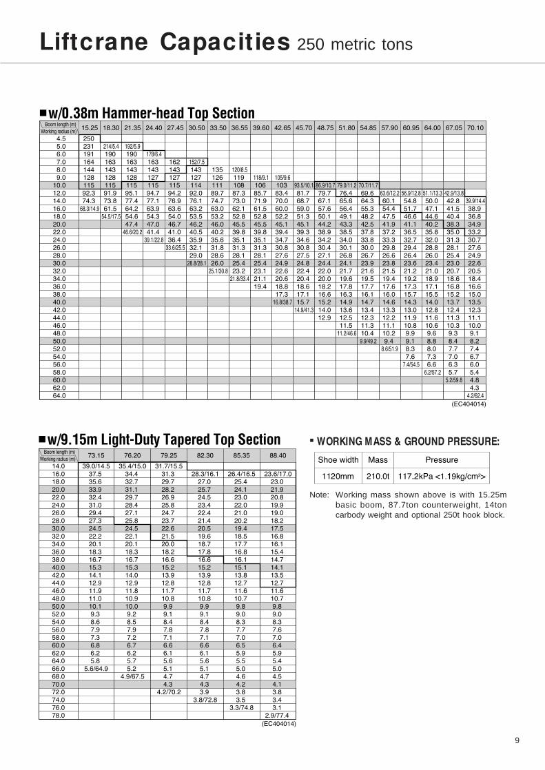
Liftcrane Capacities 250 metric tons
���
���
���
���
���
���
���
��
���
���
���
���
��
���
���
���
����
���
����
����
����
����
���
����
����
����
����
���
����
����
����
����
���
����
�������� ��� ���� ���� ����� ����� ����� ����� ���� ����� ����� ���� ����� ����� ����� ����� ����� ����
��
�
�
��
��
�
�
���
����
��������
�����
��
��
��
�
�
���
����
���
��������
�����
��
��
��
�
�
���
����
���
����
����
�������
������
��
��
�
�
����
���
����
����
����
���
������
�
��
�
�
���
����
����
����
����
���
����
��������
�����
��
�
�
���
���
���
����
���
����
����
��
���
������
��
�
����
����
����
���
����
���
����
���
���
���
�������
�����
�
��
����
����
��
���
����
����
���
���
��
���
��
�������
����
��
����
���
���
���
����
����
���
���
��
���
��
�
���
������
��
����
����
����
��
���
����
����
����
���
���
��
���
���
���
��������
�������
���
����
����
���
���
����
����
����
���
���
��
���
���
��
���
�������
��������
����
���
����
���
���
����
���
����
��
���
��
���
��
���
��
���
��
������
����
����
����
���
����
����
����
���
���
��
��
���
���
���
���
���
��
��
������
�������
����
����
����
���
���
����
����
����
���
���
��
���
���
��
���
���
��
��
���
�������
������
���
����
����
���
���
����
���
���
���
��
���
���
���
���
���
�
�
��
���
�������
�������
����
���
����
��
����
���
���
���
���
�
��
���
���
���
���
��
���
���
��
���
���
��������
������
����
���
����
���
����
���
���
���
���
��
���
��
���
���
��
��
���
���
���
���
���
���
������
�������
���
���
����
����
����
���
��
���
���
���
���
���
��
���
��
��
���
���
���
���
���
���
���
�������
��������
����
����
����
���
����
���
���
��
���
���
���
���
���
��
�
���
��
��
���
���
���
���
���
���
������
����
����
����
����
����
����
����
����
����
����
����
����
����
����
����
����
����
����
���
���
���
���
���
����
����
����
����
����
���
���
���
���
���
��� ���� ��� ����� ��� �����
��������
��
���
����
����
����
����
���
���
����
����
����
���
���
����
����
����
����
����
���
���
��
��
���
���
��
�������
�������
����
���
����
���
����
���
���
���
����
����
����
���
���
����
����
����
����
����
���
��
��
��
��
���
�
��
������
������
����
���
����
����
���
���
���
����
���
����
����
����
���
����
����
���
����
���
���
���
��
��
���
���
��
��
��
���
�������
���������
���
��
���
����
����
����
���
����
���
���
����
���
����
����
���
����
���
���
���
��
��
���
���
��
��
��
���
���
�������
��������
���
����
����
����
����
����
����
���
��
����
����
���
����
���
����
���
���
���
���
�
��
��
��
�
��
���
���
���
��
�������
��������
����
����
����
����
����
����
��
����
����
���
���
����
���
���
����
���
���
���
���
��
��
���
��
��
��
��
���
���
���
���
������
■ WORKING MASS & GROUND PRESSURE:
Note: Working mass shown above is with 15.25m
basic boom, 87.7ton counterweight, 14ton
carbody weight and optional 250t hook block.

10
Notes — Liftcrane capacities1. Capacities included in these charts are the maximum
allowable, and are based on machine standing level on firmsupporting surface under ideal job conditions.
2. Capacities are in metric tons, and are rated in accordancewith prEN13000(2003) & DIN15018/3 Standards; the figuressurrounded by bold lines are based on factors other thanthose which would cause a tipping condition.
3.Capacities are based on freely suspended loads and make noallowance for such factors as the effect of wind, suddenstopping of loads, supporting surface conditions, and operatingspeeds. Operator must reduce load ratings to take suchconditions into account. Deduction from rated capacities mustbe made for weight of hook block, weighted ball/hook, sling,spreader bar, or other suspended gear.Hook block weight is as follows:250t...........3.3ton 200t ..........3.0ton 135t .........2.6ton80t.............1.4ton 35t ............0.8ton 13.5t ........0.6ton
4. All capacities are rated for 360° swing.5. Least stable rated condition is over the side.6. A 93.7ton counterweight and 14.0ton carbody weight are
required for all capacities on these charts except thecapacities of 15.25m and 18.30m boom which require thededuction of 6ton from the 93.7ton counterweight.
7. Attachment must be erected and lowered over the ends ofthe crawler mounting.
8. Main boom length must not exceed 88.4m.Maximum fly jib length permitted — 36.55m.Maximum boom (with 0.38m hammer-head top section) andfly jib combination length permitted — 70.1m+36.55m.Maximum boom length (with 0.38m hammer-head topsection) when mounting auxiliary short jib is 70.1m.
9. Capacities when handling load off main boom head sheavesin case of mounting fly jib or auxiliary short jib on top ofboom are detailed; if required, please consult us or nearestdistributor.
10. Boom combination shall be in accordance withmanufacturer’s standard described here in “BoomCombination Diagram” of page 14.
SCX2500LF AUXILIARY SHORT JIB CAPACITIES:Max. 13.5ton
Note: Jib capacities is almost equal to the figures made by thededuction of apporx. 600kg from the liftcrane capacities forboom length up to 70.1m unless restricted by themaximum jib capacity shown above. As to the details,please consult us or nearest distributor.
Auxiliary short jib (Option)
11
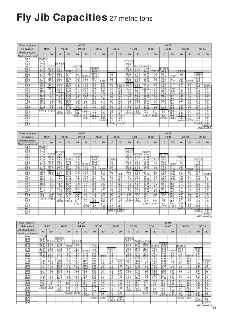
Fly Jib Capacities 27 metric tons
���� �������
�� �������
������� ���������
����� �����
�� �� �� �� �� �� �� �� �� �� �� �� �� �� �� ���� �� �� ��
����� ����� ����� ����� � ��� ����� ����� ����� ����� � ���
����!��� ���������������������������������������������������"�������"��� ����������������"��!����
����!����������������� ����� �����������������"� ���"� ���������������������""��!����
����!������� �����������"�������"�����������������"�����"� ���������"���"���"����"��
���!����
���"!������������� ��� ����� �������"��� ��������������� ������������"��
��"!�"�
� ��!����� ��� �������������"��� ��������������������������������������������"�����
�"! ���
����!��������������������������� ��������"�""��"� "��"����"������
�"! ���
���"!�"�"������� ��������"��"� "��"����"�����������������"�� ������ ����"
���!�"���� �����������"����� ������������ �� �� �� ��
���!����
������ �� � �� �� ����"����� ������������������������������
���!����
���!������������������������"�������� ������������
���!���"
����!����������������������������������������������������� �"���������������������������
���!����
����!����������������� �����������������������"������� ����� �������������������
���!� ��
����!� �����"�������"�������"�����������������"������� ��������������������� ������
���! ���
����!������� ����� ��� ����� �������"��� ����������������������������"�����
��! ���
� ��!����� ����������������� �����������������������������������"��������"����� ��
��! �"
����!������������������������������������"�""��"� "����"������ �
��"! ���
����!������� ��������"��"� "��"����"����� ��������������������� �����
���!���
�� !�"� �� �����������"������������������ �� �� �����
��"!����
���!������� �� � �� �� ����"����� �����������������"�� ���������
���!����
���!������������������������"�������� ��������������
���!����
������������� ������������������� ������������������� ������������������� �������������� ��� �������������������
�#$�������
���� �������
�� �������
������� ���������
����� �����
�� �� �� �� �� �� �� �� �� �� �� �� �� �� �� ���� �� �� ��
����� ����� ����� ����� ����� ����� ����� ����� ����� �����
� ��!��� � ��� ��� ��� ��� ��� ��� ��� �����������������������������"��� ��� ��� "�"���
��!����
� ��!����� �����"�������������������������"��� �����������������������������
��!����
����!�������������������������������"�����������"� ����������������������������� ��
���!����
� ��!����� ���������������������"��������������� ����������������"�� ��
��"!���"
����!���"���������������"��������������� �����������������������"����������" �����
���!�"��
����!������� ������������������������"�""� "��"��"���� ���������
���! ���
��� !���"������������"��"��"��"����"������������������ �� ����"���������
���! ���
���!������������� �" � �� �� �� �� ���� �������� ���
���! ��
��!���� �������������������"��������������������������������������
���!����
�����������������"����� �����������������"���
���!����
� ��!����� ��� ��� ��� ��� ��� ��� �����������"� ��������������� ������������"�� � ���
���!���
� ��!���"� ��� ��������� ���"���������������"� ��������������������������������
���!����
���"!� ���������������������"������� ����������� � ������������������������������� ���
���!����
� ��!����� ���������������������"��������������� ������������������ ����
���!� ��
����!�"�����������������"�������������������������������"������������������� ���� ��
���! ���
����!��� ��� ������������������������"�""��"��"���� ��� � ������
���! ���
����!����������������"��"��"��"��"�������������������� �" �������������"
���! �"
���!������������� �� �� �� �� �� ����"�� ������������
���! "�
��!���� ������������������������� �������������������� ��������"���
���!����
���!������������������"����� �����������������"������
��"!����
�������������������������������������������������������������������������������������������� ��� �����������"���
�#$�������
���� �������
�� �������
������� ���������
����� �����
�� �� �� �� �� �� �� �� �� �� �� �� �� �� �� ���� �� �� ��
����� � ��� �!�!� ����� ����� ����� � ��� �!�!� ����� �����
����"��� ������������������������������� ����������� �����!�����!���������������������
���"����
����"���!�����������������!���!��������� � �����������!������������������ �����
���"�!��
�!��"��� �!���!������������� ���!��� ��������� �!��� ���������������������� �����!���
!��"����
����"�����������!�������������!���!���!���!������������� ��� ���� � ����� !�
!� "����
����"�����������������!���!���!���!����� ��������������� ���!������������ ���� ��!!�!
���"�!�
����"���������������������������������� ������������ ���� ������!��
���"����
�������������� �����!������ � �� �� �� �� ���������� ���!��������
���" ���
��"���� �� ������� �����!������������������������!�����
���" ��!
���"�!���� �����!����������� ��������!���������!� !��!��!�����������
���" ���
���"����������������!��!� !��!��!��!�!!��!���� ������
���" ��
����"������������������� �����������!�����������������!�������������������������� !��
!��"����
����"���������������������!� ��� ��� ��� � �����������!������������������ ��������
!��"����
�!�!"� �!�!������������������������������� ������������� ���������������������!� ��
���"����
����"�������������������������!���!���!������������������������� ��������!��
!��"����
��� "�������������!���!���!���!����� ��������������� ���������������� ��������!�����
�� "���!
����"��� ������������������������������ ������������ �����������!��
���"� ��
���!"�������������� ������������ � �� �� �� �� ��������������!�!��!���
���" ���
��"���� �� �� ���� �����!�����������������!������!����!���
���"�!���� �����!����������� ��������!���������!� !��!��!������� ���
���" ��
���"�������������!��!� !��!��!��!�!!��!��!���� ���������
���"����
��������� �����������!������� �����������!������� ��!���!���!!��!���! �������������������������� ��� �����������
�#$!�!����

12
���� �������
�� �������
������� ���������
����� �����
�� �� �� �� �� �� �� �� �� �� �� �� �� �� �� ���� �� �� ��
����� � ��� ����� ����� ����� ����� � ��� ����� ����� �����
����!��� �����������������������"��������� �"���������������"��������"�� � ��"������
���!� ��
��� !�����������������������������"��� ����� �������"������������"����������"
��"!�"��
����!� �"��� �����������������"��� ����� ���"������������������������"������� ������
���!����
��� !�����������������������"�������������������������������� ��������������
���!����
����!��������������� �����������"���������������"����������������"� �������� ����� ���
���! ���
����!� ��������������������������"� "��"��"��"�� ������� ���������
���! ���
����!��������"�""��"��"��"�� �" �� �� �� �� �� ��������������������������
���! ��
��!���� ����"�� �����������������"�������� ������������
���! ���
�� !���������������������"�� �������������������� ��������"������������
���!������������"�� ��������������������������������"
���!"���
����!�������"�������������������������"��� �������������"������������"�� ���������� ��
���!����
����!�������������������"�����"��� ��������� �������"������������"��������������
���!����
��� !�"���������������"��� �����"���������������"�����������"��� "� �"���������������
��"!����
����!���"���������������������������������������������������� ��������������
���!� ��
����!��������������� �����������"��������������� ����������������"������� ������������
����!� � ������������������������"� "��"��"��"�� �����������������
��"! ���
����!��������"�""��"��"��"�� �" � �� �� �� �� ���� �������� ������������
��!��� ����"�������������������� ��������"�����"���������
���!"���
���!���������������������"�� �������������������� �������� ��"������
���!������������"�� ������������������������������������
����� ������������������� ������������������� ������������������� �������������������������� ��� ���"���"���
�#$�������
Notes — Fly jib capacities1. Capacities included in these charts are the maximum
allowable, and are based on machine standing level on firmsupporting surface under ideal job conditions.
2. Capacities are in metric tons, and are rated in accordancewith prEN13000(2003) & DIN15018/3 Standards; the figuressurrounded by bold lines are based on factors other thanthose which would cause a tipping condition.
3.Capacities are based on freely suspended loads and make noallowance for such factors as the effect of wind, suddenstopping of loads, supporting surface conditions, and operatingspeeds. Operator must reduce load ratings to take suchconditions into account. Deduction from rated capacities mustbe made for weight of hook block, weighted ball/hook, sling,spreader bar, or other suspended gear.Hook block weight is as follows:35t.............0.9ton 13.5t .........0.6ton
4. All capacities are rated for 360° swing.5. Least stable rated condition is over the side.6. A 93.7ton counterweight and 14.0ton carbody weight are
required for all capacities on these charts except thecapacities of 15.25m and 18.30m boom which require thededuction of 6ton from the 93.7ton counterweight.
7. Attachment must be erected and lowered over the ends ofthe crawler mounting.
8. Main boom length must not exceed 88.4m.Maximum fly jib length permitted — 36.55m.Maximum boom (with 0.38m hammer-head top section) andfly jib combination length permitted — 70.1m+36.55m.Maximum boom length (with 0.38m hammer-head topsection) when mounting auxiliary short jib is 70.1m.
9. Capacities when handling load off main boom head sheavesin case of mounting fly jib or auxiliary short jib on top ofboom are detailed; if required, please consult us or nearestdistributor.
���� �������
�� �������
������� ���������
�����
�� �� �� �� �� �� �� �� �� ��
����� ����� ����� ����� � ���
����!���"���������������������"����������� � ������������������������"����� ����"�� ��
��"!���"
���"!���������"���"��������� ����� �������������������������""����" �����������
���!���
�����"����� ����� �"� ���������"��������������� ���"����"����� ����������"���
� � !����� �������������������������������������"��������"����� ��������������
����������������������� ������� ������� ������������"��"��������������������
����!�"��������������������������"�""��"� "��"����� � �����"�����"���
����!����"�""��"��"��"����"����� �������������� ��� ������� �� ���
��"!������"�������� ������������ �" � ���� ������������
��!� �� �� �� �� ����"����� �������������������� �����������"���
���!���������"�������� ������������������������������
� ������������������� ������������������� ������������������� �������������� ��� �������������������"���
�#$�������

52 56 60 64 68 72 76 804844
100
3632242012 1684
72
68
64
60
56
84
80
88
92
96
76
52
48
44
40
36
32
28
20
16
12
24
8
4028
51.80m
48.75m
54.85m
57.90m
60.95m
64.00m
67.05m
70.10m
73.15m
76.20m
79.25m
82.30m
85.35m
88.40m
45.70m
42.65m
39.60m
36.55m
33.50m
30.50m
27.45m
24.40m
21.35m
18.30m
15.25m
1.40m
2.52
5m
30°
40°
50°
13.5t13.5t35t 35t80t135t
250t
60° 70° 80°
1000
0
6000 4700
4600
5500
5500
5200
He
igh
t a
bo
ve
gro
un
d (
m)
Working radius (m)
Hook lift allowance height:
Aux. short jib
Aux. short jib
0
4
13
Liftcrane Working Ranges
Note: This diagram just shows working ranges under 88.40m boom length as max. without fly jib.
14
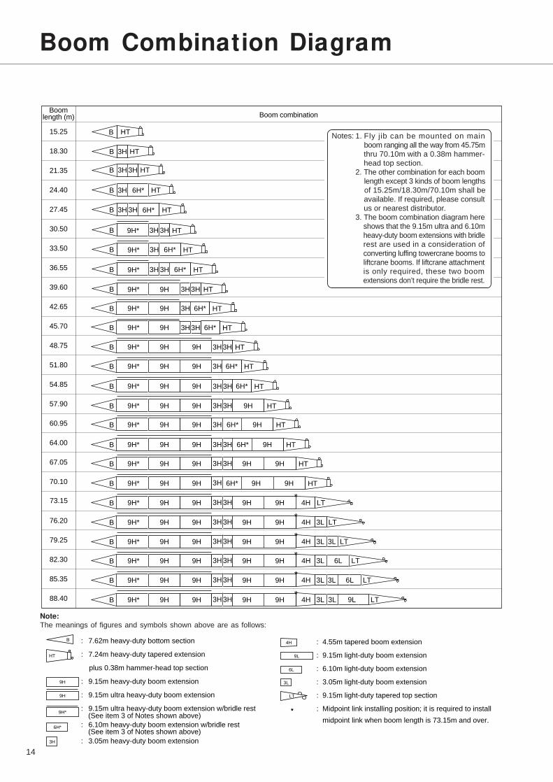
Boom Combination Diagram
Boom combinationBoom
length (m)
15.25
18.30
21.35
24.40
27.45
30.50
33.50
36.55
39.60
42.65
45.70
48.75
51.80
54.85
57.90
60.95
64.00
67.05
70.10
73.15
76.20
79.25
82.30
85.35
88.40
Notes:B
B
3H 3H HTB
3H 3HB
6H* HT
6H* HT
3H3HB 9H* HT
3H 6H*B 9H* HT
3H3H 6H*B 9H* HT
3H3HB 9H* 9H
3L 9L LT
4H 3L LT
3L LT
LT
6L LT
B 9H* 9H 9H 9H 9H 4H LT
9H* 9H 6H*
B
B
9H* 9H 3H 6H*
HT
HT
3H 6H* HT
HT
9H* 9H 9HB
9H* 9H 9HB
9H* 9H 9HB
9H* 9H 9H 9HB HT
9H* 9H 9H 6H* 9HB HT
9H* 9H 9H 9H 9HB HT
9H* 9H 9H 6H* 9H 9HB HT
B 3H
3H3H
6H* HT3H3H
3H3H
HT3H3H
3H
9H* 9H 9H 6H* 9HB HT3H3H
3H3H
3H3H
B 9H* 9H 9H 9H 9H3H3H
4H 3LB 9H* 9H 9H 9H 9H3H3H
4H 3L
3L
B 9H* 9H 9H 9H 9H3H3H
4H 3LB 9H* 9H 9H 9H 9H3H3H
4H 3LB 9H* 9H 9H 9H 9H3H3H
3H
*
*
*
*
*
*
HT
3H HT
6L
1. Fly jib can be mounted on main boom ranging all the way from 45.75m thru 70.10m with a 0.38m hammer- head top section. 2. The other combination for each boom length except 3 kinds of boom lengths of 15.25m/18.30m/70.10m shall be available. If required, please consult us or nearest distributor.3. The boom combination diagram here shows that the 9.15m ultra and 6.10m heavy-duty boom extensions with bridle rest are used in a consideration of converting luffing towercrane booms to liftcrane booms. If liftcrane attachment is only required, these two boom extensions don’t require the bridle rest.
: 7.62m heavy-duty bottom section
: 7.24m heavy-duty tapered extension
plus 0.38m hammer-head top section
: 9.15m heavy-duty boom extension
: 9.15m ultra heavy-duty boom extension
: 9.15m ultra heavy-duty boom extension w/bridle rest
: 6.10m heavy-duty boom extension w/bridle rest
: 3.05m heavy-duty boom extension
: 4.55m tapered boom extension
: 9.15m light-duty boom extension
: 6.10m light-duty boom extension
: 3.05m light-duty boom extension
: 9.15m light-duty tapered top section
: Midpoint link installing position; it is required to install
midpoint link when boom length is 73.15m and over.
9H
9H*
9H
3H
6H*
4H
3L
6L
9L
B
HT
LT
(See item 3 of Notes shown above)
(See item 3 of Notes shown above)
Note:The meanings of figures and symbols shown above are as follows:
15
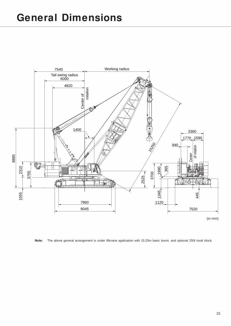
General Dimensions
Note: The above general arrangement is under liftcrane application with 15.25m basic boom, and optional 250t hook block.
7540
4820
6000C
ente
r of
rota
tion
Working radius
Tail swing radius
37
55
15
55
88
85
23
10
9045
7860
1400
15250
3360
15901770
940
19
90
37
00
25
25
13
45
36
5
1120
7520
44
5
(in mm)
Cen
ter
of
rot
atio
n

16
Standard equipment Optional equipment
Standard and Optional Equipment
¡Hydraulic tagline winder;
¡Drum rollers; available on front/rear main;
¡Stone guard; this is for operator’s cab;
¡Fire extinguisher;
¡Catwalks, along both sides of machinery
cab;
¡Built-in type full air-conditioning;
¡Re-fuel pump;
¡Heater;
¡External contracting band brakes and
clutches; required instead of standardized
automatic brake in case that a true gravity
free-fall function is necessary on front/rear
main drums;
¡Portable engine-hydraulic power pack;
required when luffing towercrane att.
Superstructure ¡Mitsubishi 6D24-TL diesel engine with a
235kW <320ps> rated output;
¡Hydraulic system with three variable
displacement axial piston pumps and one fixed
displacement duplicate tandem gear pump;
provided with an independent oil cooler;
¡Control system with two sets of triplicate
tandem valves and pilot-operated arm chair
single axis control levers;
¡Motorcycle type “SC” controller (easy-precise-
minute engine rpm and hyd. pump oil flow
control device);
¡Front and rear main operating drum winches
of 25ton l ine pull with 576mm dia. drum
lagging driven by independent variable hyd.
motor with independent hyd. circuit; each
provided with automatic brake;
¡Boom hoist mechanism with a twin-drum design
driven by two hyd. motor with automatic brakes;
¡Swing mechanism with heavy-duty turntable
bearing; driven by two hyd. motors w/spring-
applied, power hydraulically released multiple
wet-disc brakes;
¡Power hydraulically retractable A-frame gantry;
¡All new stamped, automotive type, full-vision
operator’s cab with large curved front window;
provided with an arrangement of armchair
operator control station and instrument panel;
¡93.7ton counterweight;
¡Machinery cab with hinged doors;
¡24-volt electrical system with two 12-volt batteries;
¡Lighting system:
• Two 70W working lights;
• One 10W interior cab light;
¡Anemometer;
¡Accessotes;• AM/FM radio w/clock;• Engine hourmeter;• Engine tachometer;• Fuel gauge;• Thermometer;• Hyd. oil temp. gauge;• Pilot line pressure gauge;• Foot throttle;• Intermittent dual window shield wipers withwashers;
• Cigar lighter;• Ash tray;• Book holder;• Sunvisor;• Sunshade;• Cup holder;• Non-skid surfaces;• Cab front step;• Cab floor mat;• Superstructure under-cover.
¡Std. spare parts and tools.
17
Standard equipment Optional equipment
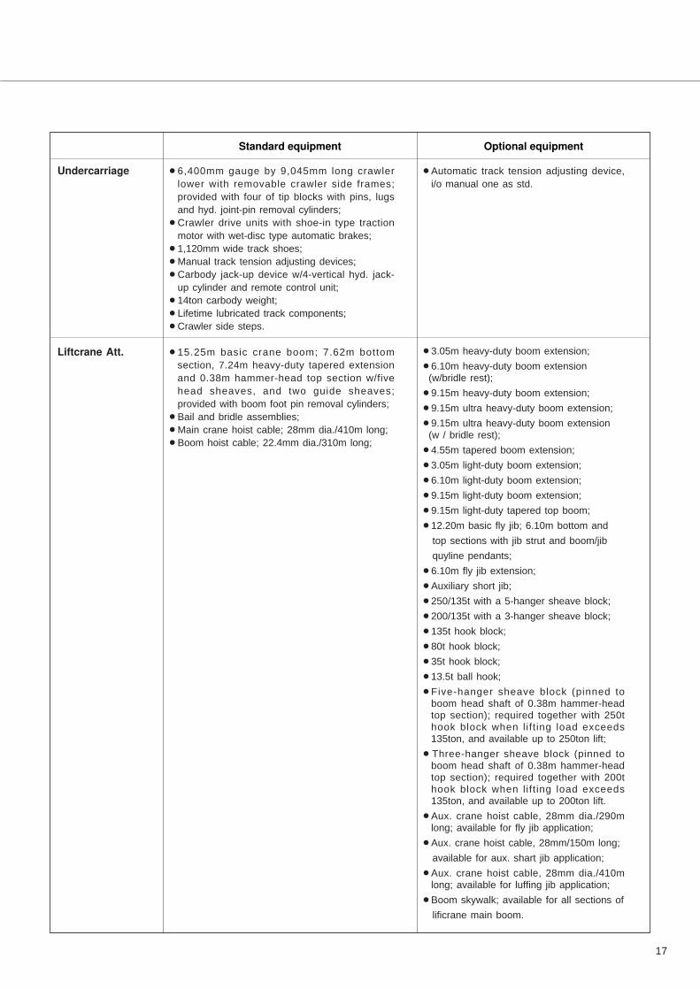
Undercarriage ¡6,400mm gauge by 9,045mm long crawler
lower with removable crawler side frames;
provided with four of tip blocks with pins, lugs
and hyd. joint-pin removal cylinders;
¡Crawler drive units with shoe-in type traction
motor with wet-disc type automatic brakes;
¡1,120mm wide track shoes;
¡Manual track tension adjusting devices;
¡Carbody jack-up device w/4-vertical hyd. jack-
up cylinder and remote control unit;
¡14ton carbody weight;
¡Lifetime lubricated track components;
¡Crawler side steps.
Liftcrane Att. ¡15.25m basic crane boom; 7.62m bottom
section, 7.24m heavy-duty tapered extension
and 0.38m hammer-head top section w/five
head sheaves, and two guide sheaves;
provided with boom foot pin removal cylinders;
¡Bail and bridle assemblies;
¡Main crane hoist cable; 28mm dia./410m long;
¡Boom hoist cable; 22.4mm dia./310m long;
¡Automatic track tension adjusting device,
i/o manual one as std.
¡3.05m heavy-duty boom extension;
¡6.10m heavy-duty boom extension (w/bridle rest);
¡9.15m heavy-duty boom extension;
¡9.15m ultra heavy-duty boom extension;
¡9.15m ultra heavy-duty boom extension (w / bridle rest);
¡4.55m tapered boom extension;
¡3.05m light-duty boom extension;
¡6.10m light-duty boom extension;
¡9.15m light-duty boom extension;
¡9.15m light-duty tapered top boom;
¡12.20m basic fly jib; 6.10m bottom and
top sections with jib strut and boom/jib
quyline pendants;
¡6.10m fly jib extension;
¡Auxiliary short jib;
¡250/135t with a 5-hanger sheave block;
¡200/135t with a 3-hanger sheave block;
¡135t hook block;
¡80t hook block;
¡35t hook block;
¡13.5t ball hook;
¡Five-hanger sheave block (pinned toboom head shaft of 0.38m hammer-headtop section); required together with 250thook block when lift ing load exceeds135ton, and available up to 250ton lift;
¡Three-hanger sheave block (pinned toboom head shaft of 0.38m hammer-headtop section); required together with 200thook block when lift ing load exceeds135ton, and available up to 200ton lift.
¡Aux. crane hoist cable, 28mm dia./290mlong; available for fly jib application;
¡Aux. crane hoist cable, 28mm/150m long;
available for aux. shart jib application;
¡Aux. crane hoist cable, 28mm dia./410mlong; available for luffing jib application;
¡Boom skywalk; available for all sections of
lificrane main boom.
18
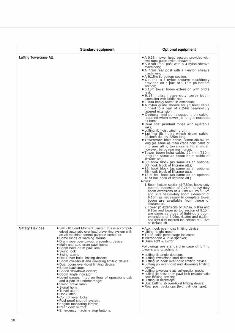
Standard equipment Optional equipment
Luffing Towercrane Att.
Safety Devices ¡SML-10 Load Moment Limiter; this is a comput-erized automatic over-load preventing system withan all-machine-control purpose computer;
¡Some kinds of warning alarms;¡Drum rope over-payout preventing device;¡Main and aux. drum pawl locks;¡Boom hoist drum pawl lock;¡Swing lock;¡Swing alarm;¡Hook over-hoist limiting device;¡Boom over-hoist and -lowering limiting device;¡Dual boom over-hoist limiting device;¡Boom backstops;¡Speed slowdown device;¡Boom angle indicator;¡Level gauge; fitted on floor of operator’s cab
and a part of undercarriage;¡Swing brake lamp;¡Signal horn;¡Travel alarm;¡Hook latch;¡Control lever locks;¡Fool proof shut-off system;¡Engine monitoring lamps;¡Rear view mirrors;¡Emergency machine stop buttons.
¡A 0.38m tower head section; provided withtwo rope guide nylon sheaves;
¡A 8.9m front post with a 4-nylon sheavemachinery;
¡A 7.3m rear post with a 4-nylon sheavemachinery;
¡A 9.15m jib bottom section;¡Optional a 3-nylon sheave machinery
provided on a part of 9.15m jib bottomsection;
¡6.10m tower boom extension with bridlerest;
¡9.15m ultra heavy-duty tower boomextension with bridle rest;
¡9.15m heavy tower jib extension;¡A nylon guide sheave for jib hoist cable
pinned to a part of 7.24m heavy-dutytapered extension;
¡Optional mid-point suspension cable;required when tower jib length exceeds51.80m;
¡Rear post pendant ropes with ajustablelinks;
¡Luffing jib hoist winch drum;¡Luffing j ib hoist winch drum cable,
22.4mm dia. by 225m long;¡Towercrane hoist cable, 28mm dia./410m
long (as same as main crane hoist cable ofliftcrane att.); towercrane hoist must,however, be by rear main drum;
¡Tower boom hoist cable, 22.4mm/310mlong (as same as boom hoist cable ofliftcrane att.);
¡80t hook block (as same as an optional80t hook block of liftcrane att.);
¡35t hook block (as same as an optional35t hook block of liftcrane att.);
¡13.5t ball hook (as same as an optional13.5t ball hook of liftcrane att.).
Notes:1. Boom bottom section of 7.62m, heavy-duty
tapered extension of 7.24m, heavy-dutyboom extensions of 3.05m/ 6.10m/ 9.15mand ultra heavy-duty boom extension of9.15m as necessary to complete towerboom are available from those ofliftcrane att.
2. Tower jib extensions of 3.05m, 6.10m and9.15m and tower jib top section of 9.15mare same as those of light-duty boomextensions of 3.05m, 6.10m and 9.15m,and light-duty tapered top section of 9.15mof liftcrane att.
¡Aux. hook over-hoist limiting device;¡Lifting height meter;¡Three color percentage indicator;¡Microphone & loud-speaker;¡Drum light & mirror.
Followings are standard in case of luffingtower-crane attachment:
¡Luffing jib angle detector;¡Luffing towercrane load detector;¡Luffing jib hook over-hoist limiting device;¡Luffing jib over-hoist and -lowering limiting
device;¡Luffing towercrane att. self-erection mode;¡Luffing jib hoist drum pawl lock (w/automatic
pawl-locking device);¡Luffing jib backstops;¡Dual Luffing jib over-hoist limiting device;¡Rear post backstops (hyd. cylinder type).

19
MEMO

• We are constantly improving our products and therefore reserve the right to change designs and specifications without notice.
• Units in this specification are shown under International System of Units; the figures in parenthesis are under Gravitational
System of Units as old one.
Printed in Japan0407(A)T02.EA031-1
Address Inquires to: