Embed Size (px)
Citation preview

ETSI GR NFV-SEC 011 V1.1.1 (2018-04)
Network Functions Virtualisation (NFV); Security;
Report on NFV LI Architecture
Disclaimer
The present document has been produced and approved by the Network Functions Virtualisation (NFV) ETSI Industry Specification Group (ISG) and represents the views of those members who participated in this ISG.
It does not necessarily represent the views of the entire ETSI membership.
GROUP REPORT

ETSI
ETSI GR NFV-SEC 011 V1.1.1 (2018-04)2
Reference DGR/NFV-SEC011
Keywords lawful interception, NFV, security
ETSI
650 Route des Lucioles F-06921 Sophia Antipolis Cedex - FRANCE
Tel.: +33 4 92 94 42 00 Fax: +33 4 93 65 47 16
Siret N° 348 623 562 00017 - NAF 742 C
Association à but non lucratif enregistrée à la Sous-Préfecture de Grasse (06) N° 7803/88
Important notice
The present document can be downloaded from: http://www.etsi.org/standards-search
The present document may be made available in electronic versions and/or in print. The content of any electronic and/or print versions of the present document shall not be modified without the prior written authorization of ETSI. In case of any
existing or perceived difference in contents between such versions and/or in print, the only prevailing document is the print of the Portable Document Format (PDF) version kept on a specific network drive within ETSI Secretariat.
Users of the present document should be aware that the document may be subject to revision or change of status. Information on the current status of this and other ETSI documents is available at
https://portal.etsi.org/TB/ETSIDeliverableStatus.aspx
If you find errors in the present document, please send your comment to one of the following services: https://portal.etsi.org/People/CommiteeSupportStaff.aspx
Copyright Notification
No part may be reproduced or utilized in any form or by any means, electronic or mechanical, including photocopying and microfilm except as authorized by written permission of ETSI.
The content of the PDF version shall not be modified without the written authorization of ETSI. The copyright and the foregoing restriction extend to reproduction in all media.
© ETSI 2018.
All rights reserved.
DECTTM, PLUGTESTSTM, UMTSTM and the ETSI logo are trademarks of ETSI registered for the benefit of its Members. 3GPPTM and LTETM are trademarks of ETSI registered for the benefit of its Members and
of the 3GPP Organizational Partners. oneM2M logo is protected for the benefit of its Members.
GSM® and the GSM logo are trademarks registered and owned by the GSM Association.
ETSI
ETSI GR NFV-SEC 011 V1.1.1 (2018-04)3
Contents
Intellectual Property Rights ................................................................................................................................ 5
Foreword ............................................................................................................................................................. 5
Modal verbs terminology .................................................................................................................................... 5
Introduction ........................................................................................................................................................ 5
1 Scope ........................................................................................................................................................ 6
2 References ................................................................................................................................................ 6
2.1 Normative references ......................................................................................................................................... 6
2.2 Informative references ........................................................................................................................................ 6
3 Definitions and abbreviations ................................................................................................................... 7
3.1 Definitions .......................................................................................................................................................... 7
3.2 Abbreviations ..................................................................................................................................................... 7
4 Problem Statement Lawful Interception in NFV ...................................................................................... 8
4.1 General ............................................................................................................................................................... 8
4.2 Security .............................................................................................................................................................. 8
4.2.1 General .......................................................................................................................................................... 8
4.2.2 Basic Trust and Default Security Stance ....................................................................................................... 8
4.2.2.1 General .................................................................................................................................................... 8
4.2.2.2 The One Deity Complex ......................................................................................................................... 8
4.2.2.3 Basic LI Security Stance ......................................................................................................................... 9
4.2.2.4 System Trust and Isolation ...................................................................................................................... 9
4.2.3 LI Function Visibility and Hiding ................................................................................................................. 9
4.2.4 Data Egress and Communication ................................................................................................................ 10
4.3 Mobility and Location ...................................................................................................................................... 10
4.3.1 Virtualised Function Location .................................................................................................................... 10
4.3.1.1 General Location and Simple VNFs ..................................................................................................... 10
4.3.1.2 Multi VNFCI VNFs .............................................................................................................................. 10
4.3.2 Inferred Location of the Target ................................................................................................................... 11
4.3.3 VNF Migration ........................................................................................................................................... 11
4.3.4 User Mobility .............................................................................................................................................. 12
4.4 Network Architecture ....................................................................................................................................... 13
4.5 Administration and Instantiation ...................................................................................................................... 13
4.6 Mediation and Egress ....................................................................................................................................... 13
4.7 Correlation and Timing .................................................................................................................................... 14
4.8 VNF Scaling ..................................................................................................................................................... 14
5 LI Architecture ....................................................................................................................................... 16
5.1 General ............................................................................................................................................................. 16
5.2 High Level Architecture ................................................................................................................................... 16
5.3 Reference Point Architecture ........................................................................................................................... 17
6 LI Deployment Scenarios ....................................................................................................................... 18
6.1 General ............................................................................................................................................................. 18
6.2 POI VNF Embedded - Trusted VNF ................................................................................................................ 19
6.2.1 Reference Diagram ..................................................................................................................................... 19
6.2.2 Components and Interfaces description ...................................................................................................... 20
6.3 POI VNF Embedded - Low-Trust VNF ........................................................................................................... 21
6.3.1 Reference Diagram ..................................................................................................................................... 21
6.3.2 Components and Interfaces description ...................................................................................................... 22
6.4 Non VNF Embedded POI ................................................................................................................................. 23
6.4.1 General ........................................................................................................................................................ 23
6.4.2 Non-Embedded POI .................................................................................................................................... 24
6.4.3 NFV Layer POI ........................................................................................................................................... 24
6.4.4 NFV External Hardware POI ...................................................................................................................... 25
6.5 LI Routing Proxy Gateway ............................................................................................................................... 25

ETSI
ETSI GR NFV-SEC 011 V1.1.1 (2018-04)4
6.5.1 General ........................................................................................................................................................ 25
6.5.2 LRPG Functionality .................................................................................................................................... 25
6.6 LI Controller ..................................................................................................................................................... 26
6.6.1 Overview .................................................................................................................................................... 26
6.6.2 LI Controller Functions .............................................................................................................................. 26
6.6.2.1 The LI Service Controller ..................................................................................................................... 26
6.6.2.2 The LI Security Controller .................................................................................................................... 26
6.7 LEMF ............................................................................................................................................................... 26
6.7.1 General ........................................................................................................................................................ 26
6.7.2 Virtualisation (vLEMF) .............................................................................................................................. 27
6.7.3 Scaling and Dynamic Configuration ........................................................................................................... 27
6.7.4 Single logical vLEMF ................................................................................................................................. 27
7 Part VNF Part Legacy Implementations................................................................................................. 27
7.1 Overview .......................................................................................................................................................... 27
7.2 General Implications ........................................................................................................................................ 28
7.2.1 ADMF ......................................................................................................................................................... 28
7.2.1.1 Backward compatibility ........................................................................................................................ 28
7.2.1.2 Standalone vs NFV Virtualised ............................................................................................................. 28
7.2.2 MF/DF ........................................................................................................................................................ 29
7.2.2.1 Backward compatibility ........................................................................................................................ 29
7.2.2.2 Standalone vs NFV Virtualised ............................................................................................................. 29
7.2.2.3 Handover Aspects ................................................................................................................................. 29
7.2.3 Mixed Legacy and Virtualised Functions ................................................................................................... 30
7.2.4 VNF Mobility ............................................................................................................................................. 30
7.2.5 Target Mobility ........................................................................................................................................... 30
7.2.6 LI Security Risks in Hybrid Deployment Scenarios ................................................................................... 31
7.2.6.1 Overview ............................................................................................................................................... 31
7.2.6.2 Virtualised Node Compromise .............................................................................................................. 31
7.2.6.3 Legacy Node Compromise .................................................................................................................... 31
7.2.6.4 Mitigations ............................................................................................................................................ 31
8 LI Solutions ............................................................................................................................................ 32
8.1 LI Deployment and Lifecycle Management ..................................................................................................... 32
8.1.1 Overview .................................................................................................................................................... 32
8.1.2 LI Deployment and Lifecycle Management Overview ............................................................................... 32
8.1.3 LI VNF instantiation ................................................................................................................................... 34
8.1.4 Embedded Virtualised POI Security Provisioning and Configuration ........................................................ 36
8.1.4.1 General .................................................................................................................................................. 36
8.1.4.2 Virtualised POI On-Boarding................................................................................................................ 37
8.1.4.3 POI Instantiation ................................................................................................................................... 38
8.1.5 Initial Communication Establishment and Certificate Provision ................................................................ 39
8.1.5.1 General .................................................................................................................................................. 39
8.1.5.2 Trusted MANO ..................................................................................................................................... 39
8.1.5.3 Low Trust MANO ................................................................................................................................. 39
8.1.6 ADMF VNFI and Connectivity Tracking ................................................................................................... 40
8.1.6.1 General .................................................................................................................................................. 40
8.1.6.2 ADMF VNFI Tracking ......................................................................................................................... 40
8.1.6.3 ADMF VNFI Connectivity Tracking .................................................................................................... 40
8.1.6.4 VNFI scaling/migration ........................................................................................................................ 41
8.2 LI Solutions Evolution Stages .......................................................................................................................... 41
8.2.1 Overview .................................................................................................................................................... 41
8.2.2 Stage 1 Evolution ........................................................................................................................................ 44
8.2.3 Stage 2 Evolution ........................................................................................................................................ 45
8.2.4 Stage 3 Evolution ........................................................................................................................................ 46
8.2.5 Stage 4 Evolution ........................................................................................................................................ 47
Annex A (informative): Authors & contributors ......................................................................................... 48
History .............................................................................................................................................................. 49

ETSI
ETSI GR NFV-SEC 011 V1.1.1 (2018-04)5
Intellectual Property Rights
Essential patents
IPRs essential or potentially essential to normative deliverables may have been declared to ETSI. The information pertaining to these essential IPRs, if any, is publicly available for ETSI members and non-members, and can be found in ETSI SR 000 314: "Intellectual Property Rights (IPRs); Essential, or potentially Essential, IPRs notified to ETSI in respect of ETSI standards", which is available from the ETSI Secretariat. Latest updates are available on the ETSI Web server (https://ipr.etsi.org/).
Pursuant to the ETSI IPR Policy, no investigation, including IPR searches, has been carried out by ETSI. No guarantee can be given as to the existence of other IPRs not referenced in ETSI SR 000 314 (or the updates on the ETSI Web server) which are, or may be, or may become, essential to the present document.
Trademarks
The present document may include trademarks and/or tradenames which are asserted and/or registered by their owners. ETSI claims no ownership of these except for any which are indicated as being the property of ETSI, and conveys no right to use or reproduce any trademark and/or tradename. Mention of those trademarks in the present document does not constitute an endorsement by ETSI of products, services or organizations associated with those trademarks.
Foreword This Group Report (GR) has been produced by ETSI Industry Specification Group (ISG) Network Functions Virtualisation (NFV).
Modal verbs terminology In the present document "should", "should not", "may", "need not", "will", "will not", "can" and "cannot" are to be interpreted as described in clause 3.2 of the ETSI Drafting Rules (Verbal forms for the expression of provisions).
"must" and "must not" are NOT allowed in ETSI deliverables except when used in direct citation.
Introduction Virtualised CSP networks are required to be able to support lawful interception and other mandatory regulatory requirements. Lawful Interception (LI) as detailed in ETSI GS NFV-SEC 004 [i.1], needs to be performed in a way that is transparent to both the targeted user and non-authorized CSP personnel. In addition, LI needs to be implemented in security domain isolation from other general CSP network functions.
In a virtualised network, many of the legacy "Security by Obscurity" and physical hardware based approaches for hiding Lawful Interception are no longer viable, either due to mobility of virtualised network functions or as a result of the common hypervisor/compute architecture on which virtualised networks are based. Therefore, the virtualised network functions need to provide equivalent transparency and security solutions compared to existing legacy hardware networks. In order to support this, it is necessary for both the NFV platform on which the virtualised function/application is running and the underlying hardware platform to provide a set of standard secure building blocks on which the virtualised network function/application can be implemented.

ETSI
ETSI GR NFV-SEC 011 V1.1.1 (2018-04)6
1 Scope The present document provides a study of the virtual functions which are required to support LI in ETSI NFV based virtualised networks. The present document identifies the set of capabilities, interfaces, functions and components which can be utilized by the virtualised applications (VNFs) to provide Lawful Interception. The present document identifies top to bottom (Virtualised Application through NFV layer through hardware platform) LI architectures and identifies within the scope of ETSI NFV, capabilities, interfaces, functions and components required to support these architectures.
The present document has 3 primary objectives:
1) Identify and define 1 or more NFV reference LI architectures, including administration functions, virtual points of interception, mediation functions and other LI functions. This is intended to provide a common reference architecture which can be used to identify functional split across the Virtualised Network Functions application layer (e.g. 3GPP Network), NFV software platform layer (ETSI NFV) and Hardware Platform layer.
2) Identify potential NFV solutions which provide the capabilities, interfaces, functions and components to meet the identified LI architectures. This is intended to identify all of the elements and interconnection relationships needed to perform LI in a virtualised network. These will form the basis for future normative standardization in both ETSI NFV and other bodies such as 3GPP utilizing ETSI NFV to virtualise their network functions.
3) Document deployment scenarios examples for each of the identified reference LI architectures. This is intended to show specific examples for different types of interception (e.g. on switch/function vs probe based) in specific technology deployment scenarios (e.g. 3GPP).
2 References
2.1 Normative references Normative references are not applicable in the present document.
2.2 Informative references References are either specific (identified by date of publication and/or edition number or version number) or non-specific. For specific references, only the cited version applies. For non-specific references, the latest version of the referenced document (including any amendments) applies.
NOTE: While any hyperlinks included in this clause were valid at the time of publication, ETSI cannot guarantee their long term validity.
The following referenced documents are not necessary for the application of the present document but they assist the user with regard to a particular subject area.
[i.1] ETSI GS NFV-SEC 004: "Network Functions Virtualisation (NFV); NFV Security; Privacy and Regulation; Report on Lawful Interception Implications".
[i.2] ETSI TS 102 232-1: "Lawful Interception (LI); Handover Interface and Service-Specific Details (SSD) for IP delivery; Part 1: Handover specification for IP delivery".
[i.3] ETSI GS NFV-SEC 009: "Network Functions Virtualisation (NFV); NFV Security; Report on use cases and technical approaches for multi-layer host administration".
[i.4] ETSI GS NFV-MAN 001: "Network Functions Virtualisation (NFV); Management and Orchestration".
[i.5] ETSI GS NFV 002: "Network Functions Virtualisation (NFV); Architectural Framework".

ETSI
ETSI GR NFV-SEC 011 V1.1.1 (2018-04)7
[i.6] ETSI TS 133 108: "Universal Mobile Telecommunications System (UMTS); LTE; 3G security; Handover interface for Lawful Interception (LI) (3GPP TS 33.108)".
[i.7] ETSI GS NFV-SEC 012: "Network Functions Virtualisation (NFV) Release 3; Security; System architecture specification for execution of sensitive NFV components".
[i.8] ETSI GS NFV-SEC 013: "Network Functions Virtualisation (NFV) Release 3; Security; Security Management and Monitoring specification".
[i.9] ETSI TS 133 107: "Universal Mobile Telecommunications System (UMTS); LTE; 3G security; Lawful interception architecture and functions (3GPP TS 33.107)".
[i.10] ETSI GR NFV-SEC 016: "Network Functions Virtualisation (NFV); Security; Report on location, timestamping of VNFs".
[i.11] ETSI GR NFV-SEC 007: "Network Functions Virtualisation (NFV); Trust; Report on Attestation Technologies and Practices for Secure Deployments".
3 Definitions and abbreviations
3.1 Definitions For the purposes of the present document, the terms and definitions given in ETSI TS 102 232-1 [i.2], ETSI TS 133 107 [i.9] and the following apply:
LI Virtual Machine (LI VM): dedicated virtual host containing a virtual Point of Interception
virtual point of interception: dedicated LI function which may be either a dedicated VNFCI within a VNFI or a separate VNFI in its own right targeting traffic from other VNFIs
3.2 Abbreviations For the purposes of the present document, the abbreviations given in ETSI TS 102 232-1 [i.2], ETSI TS 133 107 [i.9] and the following apply:
ADMF Administration Function CA Certificate Authority DF Delivery Function HI Handover Interface HI1 Handover Interface 1 HI2 Handover Interface 2 HI3 Handover Interface 3 LEA Law Enforcement Agency LEMF Law Enforcement Monitoring Function LI Lawful Interception LI VM Lawful Interception Virtual Machine LoA Level of Assurance LRPG Lawful Interception Routing Proxy Gateway MF Mediation Function POI Point Of Interception RD Retained Data SDN Software Defined Network SO Security Orchestrator TCF Triggering Control Function TTP Trusted Third Party vDF virtualised Delivery Function vMF virtualised Mediation Function vPOI virtualised Point Of Interception

ETSI
ETSI GR NFV-SEC 011 V1.1.1 (2018-04)8
4 Problem Statement Lawful Interception in NFV
4.1 General This clause outlines the overall challenges which should be addressed when considering how and where to deploy Lawful Interception functionality in an NFV environment. These challenges form the basis of the problem set which any LI architecture should be able to overcome, as detailed in subsequent clauses of the present document.
Details for the underlying LI requirements and internal LI VM functionality are given in ETSI GS NFV-SEC 004 [i.1] and ETSI TS 102 232-1 [i.2].
4.2 Security
4.2.1 General
NFV does not necessarily introduce any new security challenges for lawful interception which did not otherwise exist in legacy networks. In fact, a properly implemented NFV network may actually provide better LI security than legacy networks which have historically provided security by obscurity. What NFV does in practice is remove the obscurity option and force implementers to secure LI properly.
Within the scope of the present document, LI architectures and solutions should trade-off security/detectability, against the actual ability to reliably perform LI in dynamic virtualised environments. The LI security details in this clause are intended as a guide only and are aimed at highlighting a number of the restrictions that LI requires that may not be familiar to those not familiar with legacy LI implementations. Detailed security threats, solutions and mitigation approaches are provided in ETSI GS NFV-SEC 004 [i.1], ETSI GS NFV-SEC 012 [i.7] and ETSI GS NFV-SEC 009 [i.3].
Specific consideration of LI security challenges in hybrid part legacy scenarios is given in clause 7.2.6.
4.2.2 Basic Trust and Default Security Stance
4.2.2.1 General
While ETSI GS NFV-SEC 012 [i.7] contains generic security requirements for sensitive functions, it is important to consider the fundamental LI specific security requirements that any NFV implementation requiring LI should be able to address.
4.2.2.2 The One Deity Complex
NFV and other IT cloud systems are typically built on the assumption that there is one root administrator who has absolute dominion over all software and resources in a system. Unfortunately that approach is not entirely compatible with LI, unless they are a member of the LI administration team that controls the rest of the network. While LI is always under the control of the CSP, most general network administration and support personnel will not be authorized to have control, knowledge or visibility of LI. Therefore it is necessary to be able to separate administration of LI from other network functions or processes. It is entirely reasonable for the primary root admin to have a role in initial enabling of LI when the network is initially built (or if LI needs to be retrofitted at a later date). However, once LI is enabled (with or without the main system root admin), LI from then on needs to be entirely invisible to the main network root admin and they should not be able to interfere with, inspect or monitor any aspect of LI unless they are specifically permitted to do so. This sets a very high bar but is the start point any NFV based LI implementation needs to start from.
For LI, the ADMF is considered to be the ruler of all other LI functions (with the exception of the LEA LEMF). All decisions and aspects of control ultimately sit with the ADMF (see clause 4.5).

ETSI
ETSI GR NFV-SEC 011 V1.1.1 (2018-04)9
4.2.2.3 Basic LI Security Stance
LI is generally considered to be a security sensitive issue and as such the knowledge of the existence of LI and LI target lists is typically subject to high security restrictions. Therefore, LI needs to be considered a highly sensitive network with all of the isolation and security requirements that such government systems require. However, given that if an LI system was considered government classified then the network to which it connects and all users would need to be subject to the same security restrictions.
That is clearly impractical for a public communications network. However, when considering how to implement LI securely in an NFV network, the start point should always be that LI is a high security, restricted system requiring absolute isolation and then design an implementation which sticks as close to that principle as possible within the limits of practicality for a public communications network.
Therefore, LI needs to be fully self-contained within a single legal jurisdiction (generally a single country), should not be visible or detectable to non-LI authorized entities (systems, processes or people), cannot rely on any information which would have to be specifically provided for an LI targeted communication which would otherwise not be available for a non-LI target communication. In general LI cannot be shared across operators and given the legal jurisdiction restriction, LI cannot be implemented in one country to provide LI capability for another.
4.2.2.4 System Trust and Isolation
By default, the LI Functions do not trust generic network resources or hardware which are not specifically dedicated to LI and under full audit control of the LI system. As such while placing LI encryption keys or target lists in hardware security modules mitigates some LI security requirements, unless these are specifically dedicated to LI, such hardware security modules would be considered untrusted. Therefore they are only a part of any overall LI security solution.
In order for LI to work, it needs to fundamentally exist to some degree within the main CSP NFV resources in order to gain access to target communications. However, while it needs to exist in the main network, only those aspects, processes or functions which need to be exposed should be exposed (e.g. LI VNFCI interfaces to send or receive LI data). Everything else should be fully secured using secure exclaves and other applicable security solutions as detailed in ETSI GS NFV-SEC 012 [i.7]. LI should be implemented in a logically separated trust domain. This is similar to basic NFV security isolation requirements for VNFs or slicing but for LI this needs to be implemented fully top to bottom (application layer through to the hardware) and not just NFV layer and above.
Since data needs to enter and leave the LI functions, implementations cannot simply assume that placing LI functionality inside secure enclaves is sufficient. LI security design should adequately protect the LI functions themselves and anything connected to them. Therefore, LI requires that the wider network in which it has been implemented also natively utilize many of the same fundamental security capabilities required for LI.
All key material and LI target lists should be protected in either secure enclaves or hardware security modules. Once any resources used for LI are no longer required all memory, storage (including hardware security modules) should be erased to government security standards to ensure no data is recoverable. LI should always fail safe such that under all error, crash or failure scenarios no LI data, keys or target lists can ever be exposed outside of the LI trust domain. LI information should be dead, not merely resting.
4.2.3 LI Function Visibility and Hiding
Securing and hiding LI functionality from other functions in an NFV environment is by far the largest initial challenge. Placing LI functions within the VNF environment exposes them to a variety of security and visibility risks. Placing them outside of the NFV environment comes with a different set of visibility risks, places significant constraints on VNF mobility, makes LI fragile to dynamic changes in the NFV environment and will only be possible in scenarios where the mandatory intra VNFI and inter VNFI encryption has been disabled. Disabling intra/inter VNFI encryption will expose the NFV platform to considerable Cyber risks and is therefore unlikely to be acceptable.

ETSI
ETSI GR NFV-SEC 011 V1.1.1 (2018-04)10
4.2.4 Data Egress and Communication
Beyond the basic security considerations for the virtualised LI functions themselves, LI functions require to be tasked with interception warrants and be able to transfer the resulting intercepted data between themselves and the LEA LEMF. In an NFV and SDN network, the HI and X interfaces generally need to start and end in virtualised functions. VPNs or other network paths used to route the LI data will be far more visible to the rest of the network than in legacy implementations. Current HI and X interface protocol security is generally designed to protect data between physically secure end points and in many cases using VPN and/or network links which use dedicated "hidden" infrastructure. Furthermore, in a fully NFV and SDN network, the LEMF end points will need to be fully visible to the NFV MANO and SDN controllers in order to ensure that intercept can be maintained as the network evolves (e.g. VNFI relocation, etc.).
4.3 Mobility and Location
4.3.1 Virtualised Function Location
4.3.1.1 General Location and Simple VNFs
After security, underlying mobility of the virtualised network (both logically and physically) is the biggest challenge for implementing LI in an NFV environment. The LI management functions needs to be able to figure out what the network architecture looks like at any point in time and where to place POIs (and therefore LI VMs) relative to the changing architecture in real-time. Furthermore, the LI management functions should be adapted to or able to monitor changes which impact LI VM placement, routing, interconnection or underlying VNF interconnectivity (and therefore target traffic routing) and make any necessary changes in real-time.
In terms of LI VM location, the LEMF/ADMF should be able to request assurance that the LI VMs and any other elements involved in the LI service are within the pre-defined location constraints which the NFV MANO layer has been given. For example, if a network has been implemented in 5 data centres, 4 in the jurisdiction of LEA and 1 outside, then the MANO needs to be able to attest to the ADMF/LEMF that the LI VMs (and any VNF from which they are taking target traffic) are running as pre-configured, in any of the 4 in jurisdiction data centres. It is this ability to attest this location geo fencing that is important and not necessarily whether LI VM process 12345 was for 20 ms on VM blade 66666, rack 7 sub-shelf 4, data centre A, address: 123 The Street, Long X:Lat Y.
In addition to the need to attest the location of LI VMs and their associated parent VNFIs, in many cases VNFIs with LI functionality need to obtain real-time target specific information from other peer VNFIs. Therefore, it is not a simple as needing to control and attest the location of single LI equipped VNFIs but rather groups of VNFIs. In such groups, the other non-LI VNFIs could be either directly or indirectly involved in supporting LI. For single vendor implementations where groups of VNFIs are directly involved in supporting LI, then it may be possible to group them directly via MANO using the software catalogues and VNFDs. However, more indirect scenarios where VNFIs may not be directly aware of LI are potentially more challenging to address (e.g. maintaining non-detectability when the non-LI VNFI scale or migrate).
As a minimum, the ability to attest that LI VMs are running within the defined MANO placement rules will be required for all VNFIs. In some specific scenarios real, geographic location of specific LI VMs may be required. Attesting real world location LI VMs requires additional hardware beyond that implemented for traditional cloud service infrastructures and may therefore add significant cost if it was applied to all hosts and all VNFIs. Changes to hypervisor, firmware, MANO, OSs and VMs would also potentially be required to achieve full attestation of LI VMs.
Further guidance on location and associated timestamping is given in ETSI GR NFV-SEC 016 [i.10].
4.3.1.2 Multi VNFCI VNFs
Where a VNFI is composed of multiple VNFCIs and those VNFCIs are spread across multi hosts, location of the LI POIs becomes considerably more complicated. In legacy networks, large network elements have a single logical location. When those large functions become virtualised they will be implemented with potentially 100 s of physical hosts. Those hosts do not need to be in the same rack, data centre or physical location.

ETSI
ETSI GR NFV-SEC 011 V1.1.1 (2018-04)11
It is therefore necessary to consider which location used, attested or reported for LI purposes. The location of VNFCI running the vPOI within the VNF might be an obvious choice but there may be multiple vPOI VNFCI within a single VNFCI and left unrestricted the vPOI VNFCI could be in a different location to the VNFCI serving the actual target user data flow. Conversely the VNFCI handling the target user data flow may be a better choice (especially if that directly related to user location - see clause 4.3.2) but again there are likely to be more than 1 of those. Furthermore, some functions in virtualised networks may be purposely distributed.
The exact meaning, location and binding of the individual locations for each host relative to the each overall VNFI is outside the scope of ISG NFV. However, it will be necessary to ensure that sufficient location information (physical location or confirmation that the VNFCI is within the host allocation constraints attested by MANO), is made available for LI purposes.
4.3.2 Inferred Location of the Target
With exception of UE assisted (e.g. GPS) or other network enhanced location technologies, Lawful Interception does not typically obtain the actual location of the target subscriber. Instead the location is inferred from the location of network equipment to which it is attached. The accuracy of this location is therefore related to the technology used and density of the radio infrastructure to which the UE connects.
For legacy networks, in its simplest form location could be the postcode of a single standalone WLAN hotspot. In 3G/4G or other more complicated mesh technologies, the location derived from the infrastructure is associated with multiple elements in the network. For example, a CellID is a combination of the antenna mast ID and other parameters. Since the infrastructure does not change very often it is possible to derive accurate inferred location of the target.
With NFV, since the VNFs making up the service can change on a frequent basis, one or more elements of the information from which the CellID or other equipment associated location information is obtained may become dynamic. This may result in the location appearing to change rapidly for a static subscriber or indeed a highly mobile subscriber appearing to have a constant location as the VNFs move with user mobility. It may not be possible in some scenarios to obtain a location at all in some scenario, based on legacy static approaches.
Since the equipment ID, naming schemes, CellIDs or other equipment based location information are a VNF service level issue, it is not possible to precisely identify or mitigate all of the possible live deployment models. However, for the LEA to continue to rely on VNF associated location or identities to infer target location, the CSP will need to provide LEAs with near real-time network state information from which the equivalent to the static legacy network locations can be constructed.
4.3.3 VNF Migration
VNFI migration is not actually new. CSPs have a long history of deploying network functions in load balanced arrays or in hot standby configurations such that target traffic can migrate between multiple physical network functions. However, these elements are generally presented to the world as a single logical function, migrations are infrequent and they are in a small number of static locations.
There are two types of VNFI logical migration; Migration of the live service from one VNFI to another VNFI; and migration of the running VNFI from one set of hosts to another. These are shown in figure 4.3.3-1.

ETSI
ETSI GR NFV-SEC 011 V1.1.1 (2018-04)12
Figure 4.3.3-1: Simplified LI Migration for embedded vPOIs
In the case of a live service migration from one VNFI to another VNFI, while there are challenges in making sure the configured LI capabilities are available in the new VNFI before the service migrates, this is actually very similar to load balancing or other migrations which already occur in legacy networks. The frequency of migrations may be higher but NFV does not cause any significant new issues for LI that did not already exist in the legacy case. VNFI IDs are likely to change and it is therefore potentially easy for the LI systems to detect and correlate for these migrations.
In the case of the migration of a running VNFI from one set of hosts to another, this is potentially more difficult to handle. Firstly, the identifiers at the application level may not change, which may impact reported user location. Secondly it means that the location binding of hosts to VNFCI (as discussed in clause 4.3.1) should be performed continuously and not just at initial instantiation of the VNFCI.
Similar to migration of a whole VNFI, it is possible for one or more VNFCIs to migrate (or indeed the number of VNFCIs could change). The implications for LI are essentially the same as for a whole VNFI live migration, but the effects may be more difficult to detect and the effects on any on-going interception are likely subtler.
NOTE: The extent to which current hardware and MANO implementations support real-time live migrations is unclear and expected to be infrequent in the short - medium term. However, since LI location reporting capabilities may be difficult to retrofit, VNFI migration needs to be considered.
While migration of VNFs does not generally alter the functionality or intercepted traffic characteristics, scaling as discussed in clause 4.8 may cause similar impacts to the ability to maintain and operate LI in a virtualised network. If scaling results in new VNFCIs in substantially different locations to that of existing VNFCIs or scaling results in exceeding the capacity of the existing LI POI VNFCI then the effects of migration and scaling can be considered to be similar from an LI perspective. Both migration and scaling should therefore be considered together in any implementation.
4.3.4 User Mobility
In a static legacy network, as a user moves through the radio environment of a mobile technology (e.g. 4G) or physically moves from one physical Ethernet connection to another, the UE moves between different physical elements of the network. Those changes result in inferred or actual location information changes as reported to law enforcement.
With NFV deployments, the movement of 1 or more users may impact the logical structure of the VNFIs serving those users. The higher the overall level of user mobility the larger the changes which may occur on the network side to adapt the network to maintain optimum user experience.
For LI, the relationships between physical user mobility and the corresponding changes in information reported to the LEA may become more dynamic. User mobility may cause a higher degree of vPOI migration than for an equivalent level of mobility in a legacy network. This makes issues such as LI dimensioning more difficult to achieve without reserving higher levels of spare resources.
Communication MANO Control
LI Admin Control
USER
vMF/vDF
MANO
ADMF
SERVICE
VNFI 2
vPOI2
SERVICE VNFI 1
vPOI1
CSP NFV
Network
USER
vMF/vDF
MANO
ADMF
Host 2
VNFI 1
vPOI1
Host 1 VNFI 1
vPOI1
CSP NFV
Network
Service level migration between VNFIs VNFI level migration between Hosts

ETSI
ETSI GR NFV-SEC 011 V1.1.1 (2018-04)13
While still theoretically possible in a legacy network, mobility of non-target users may have a large impact on individual VNFIs used by a target, both when the target is mobile and when the target is static. This means that VNFI location and target user location may evolve into a multi-dimensional dynamic relationship.
4.4 Network Architecture In order to reliably intercept target communications and stand any chance of reconstructing them at the LEMF, the CSP LI system and the LEMF need to be implicitly aware of the relative network architecture across which a target communication is travelling. This extends to both the core network functions involved in actually intercepting the target traffic and any associated network functions which those LI core network functions rely on to perform LI (e.g. subscriber databases, routing control functions, authentication proxies and identity management functions).
In an NFV environment, the LEMF should be able to arrive at the same user service contextual state and architectural relationships (i.e. the instantaneous dynamic relative meaning of metadata, relative to where in the service chain this to relates and which architectural functions are communicating with which other functions), while the functions responsible for LI management in the CSP network should be able to place LI functionality in the correct places and communicate where required the instantaneous relations to the LEMF as part of any interception.
4.5 Administration and Instantiation Within the ETSI TC LI, LI architectures defined in ETSI TS 102 232-1 [i.2], the ADMF is responsible for administering target warrants and commanding the POI and MF/DFs to take the necessary actions to capture communications of a given target. This is based on the ADMF knowing how many POIs and MF/DFs it has under its control. In an NFV environment the ADMF has to dynamically adapt to the changing number of POIs and MFs required.
The ADMF can either logically request the MANO to instantiate LI VNFIs on a request basis, or the ADMF needs to be told that new LI VNFIs (vPOI and vMF/vDF) have been created and need configuring. In the request case, the ADMF would need to be constantly informed of changes in logical VNF topology, interconnection and scaling, in order to make decisions about where an LI vPOI might be needed.
In the second case, where the LI VNFIs are automatically created by MANO, this places less of a topology mapping load on the ADMF but requires more careful design and securing of the VIM/VNF libraries to ensure VMs with the correct functionality are automatically created when a VNF which needs to be LI capable, is instantiated or a new network logical interconnection requires an LI vPOI to monitor it. In this case, the LI vPOIs would need to be able to announce themselves securely to the ADMF using some form of pre-allocated boot credentials and then be fully configured by the ADMF prior to capturing live target traffic.
Except where mandated otherwise by national law, the ADMF is an internal CSP function, under the full control and administration of the CSP.
Further consideration on ADMF implementation is given in clause 7.2.
4.6 Mediation and Egress Assuming it has been possible to place an LI vPOI in the correct logical place in the network to intercept the required target traffic, then the LI vPOI needs to pass the intercepted traffic to the LI Mediation Function (MF)/Delivery Function (DF) which formats the traffic (e.g. according the ETSI TS 102 232-1 [i.2]), before forwarding it to the LEMF. Traditionally the MF/DFs are either implemented as large concentration points serving multiple points of intercept (POIs) or a single MF/DF may be integrated with each legacy POI.
In an NFV environment, it may be desirable for security reasons to place the MFs outside of the NFV platform in which the LI vPOIs are implemented. However, as the LI vPOIs move and change in scale, this may make the routing complexity required to backhaul traffic from the LI POIs to the MF/DFs unacceptable. It would potentially be difficult to adequately hide the routing/traffic flows in an SDN connectivity environment.
By comparison using vMF/vDFs in the NFV environment makes implementation and routing much easier. However, using vMF/vDF in the NFV domain then moves the problem down the chain to the handover interfaces (HI2, HI3 as defined in ETSI TS 102 232-1 [i.2]). Again, NFV combined with SDN will make hiding large backhaul pipes to a fixed location hardware LEMF difficult to achieve.

ETSI
ETSI GR NFV-SEC 011 V1.1.1 (2018-04)14
Even if the vMF/vDF is in the NFV environment then having multiple vPOIs sending intercepted traffic to a single vMF/vDF may cause similar routing issues to the external MF/DF case if the vPOIs and vMF/vDF are allowed to physically move or scale independently. However, having a 1 to 1 relationship between vPOIs and vMF/vDFs is likely to be inefficient and cause scaling issues with ADMF or LEMF.
The obvious logic final step would be to also move the LEMF into the NFV cloud environment or use a Trusted Third Party (TTP) middle proxy to provide the separation between the vMF/vDFs and the fixed hardware LEMF. However, the LEMF's national security requirements may make this difficult to achieve for some LEAs.
Further consideration on MF/DF or vMF/vDF implementation is given in clause 8.2.
4.7 Correlation and Timing Traditionally LI correlation relies on knowing the fixed relationship between network architecture, target identifiers, location of the POIs/MFs (not the actual physical location but rather the logical location relative to each other in space and time) and the warrant parameters provided by the LEA. However, in NFV, as a minimum the network architecture and therefore the VNF IDs become dynamic. Therefore, the correlation scheme used needs to be able to support dynamic real-time correlation using dynamic relative real-time identifiers linked to 1 or more static warrant IDs.
Similarly, in legacy LI, because the relative physical location of nodes is known and is static, providing timestamps are of a sufficiently granular resolution and accuracy, then providing the network uses Network Time Protocol (NTP) synchronization, timestamps are not usually a major issue. However, for NFV if both the core network nodes are dynamic relative to the LI VNFIs and both are dynamic relative to the MFs, then timestamp accuracy and intercepted target event ordering at the LEMF becomes much more difficult.
This gets worse with distance. For example, in current LI implementations, millisecond resolution is too coarse when the physical speed of light routing delay is larger than the minimum timestamp increment (large countries such as USA or China may encounter this issue or in any network utilizing satellite links). For traditional LI, the MF can compensate for this implicitly because the routings are fixed and the inter-relationship between POIs is known.
Similarly, low delay 5G services (end to end and communications setup delays) may demand higher LI timing accuracy than in legacy networks. In addition, timing and correlation resolution/accuracy needs to be better than the fastest MANO initiated network changes, where those changes impact LI.
ETSI GR NFV-SEC 016 [i.10] provides some further detailed consideration on aspects of the correlation and timing but the upshot is that any NFV implementation should be able to fully correlate all intercepted traffic, adapt faster than the fastest LI impacting VNFI changes and ensure that all timestamps are of sufficient resolution, accuracy and precision to support real-time LI and/or RD.
4.8 VNF Scaling In current legacy networks, major network functions may provide service to 10 000 s up to 1M+ users. However, for NFV, virtualised functions can either be deployed to mirror the existing large monolithic elements model (which makes the logical network simpler) or lots of smaller VNFs can be instantiated serving 1 to a few 1 000 users (which is probably more efficient in resource terms but makes logical network more complex). Each of these two scaling approaches has a significant impact on LI.
Figure 4.8-1: Large vs Small user handling capacity VNF scaling

ETSI
ETSI GR NFV-SEC 011 V1.1.1 (2018-04)15
Figure 4.8-1 illustrates the two models, either emulating legacy architectures or with large numbers of smaller simple VNFs. For the large virtualised functions, the VNF will require lots of parallel VMs in order to provide the equivalent scaling to a legacy hardware node. This logically results in multiple parallel VMs all performing the same function (e.g. 20 parallel VMs implementing a RADIUS sub-function). Therefore, each large VNF may end up with multiple parallel LI VMs within the single VNF. A vMF/vDF may need to interact with each LI VM as if it was a separate vPOI, as a single VM acting as a multiplexer may cause LI bandwidth limitations (which is why a large VNF may require multiple LI VMs in the first place). As user traffic moves internally between different duplicated parallel logical functions within the VNF, the LI traffic for a specific target may switch LI VMs. While this architectural approach seems highly undesirable from an LI implementation perspective it is unlikely be possible to entirely avoid this in large VNFs, which make the service level network easier to manage.
By comparison the small scale 100 or 1 000 user single server VNF is much simpler to implement and control from an LI perspective. However, the simplicity in implementation at single VNF level is traded off against having much higher number of more dynamic VNFs. As a result, the number of vPOIs may increase by 1 000+ times. This makes issues such as vPOI certificate management, auditing and vPOI LI target list management much more complicated.
Large vs Small VNF characteristics can be summarized as follows.
Table 4.8-1
Large VNF Characteristics from LI perspective Small VNF Characteristics from LI perspective • Hundreds of VMs per VNF • 1 VM = 1 Hardware Unit • LI scattered across many VMs in single
virtualised function • VMs can move independently • Overall VNF mobility low • Inefficient at IT layer • Less flexible • Creation and termination less frequent • Closest to Legacy Architecture • More DPI tolerant
• A few of VMs per VNF • All VM = 1 or less hardware units • LI in 1 (or very few) VMs • VMs do not move independently within VNF • Overall VNF mobility extremely high • Efficient at IT layer • Creation and termination more frequent • Very Flexible • 1 000+ times increase in parallel network
functions compare with Legacy Networks • Only "On-Switch/Function" LI scalable
ETSI
ETSI GR NFV-SEC 011 V1.1.1 (2018-04)16
5 LI Architecture
5.1 General ETSI TS 102 232-1 [i.2] and ETSI TS 133 107 [i.9] define lawful interception architectures as implemented today in many fixed and mobile networks. While the fundamental application service level LI functionality may not change significantly in virtualised networks, this clause identifies new functions which would be required in a virtualised environment to adapt existing ETSI and 3GPP LI architectures to these new network deployment scenarios.
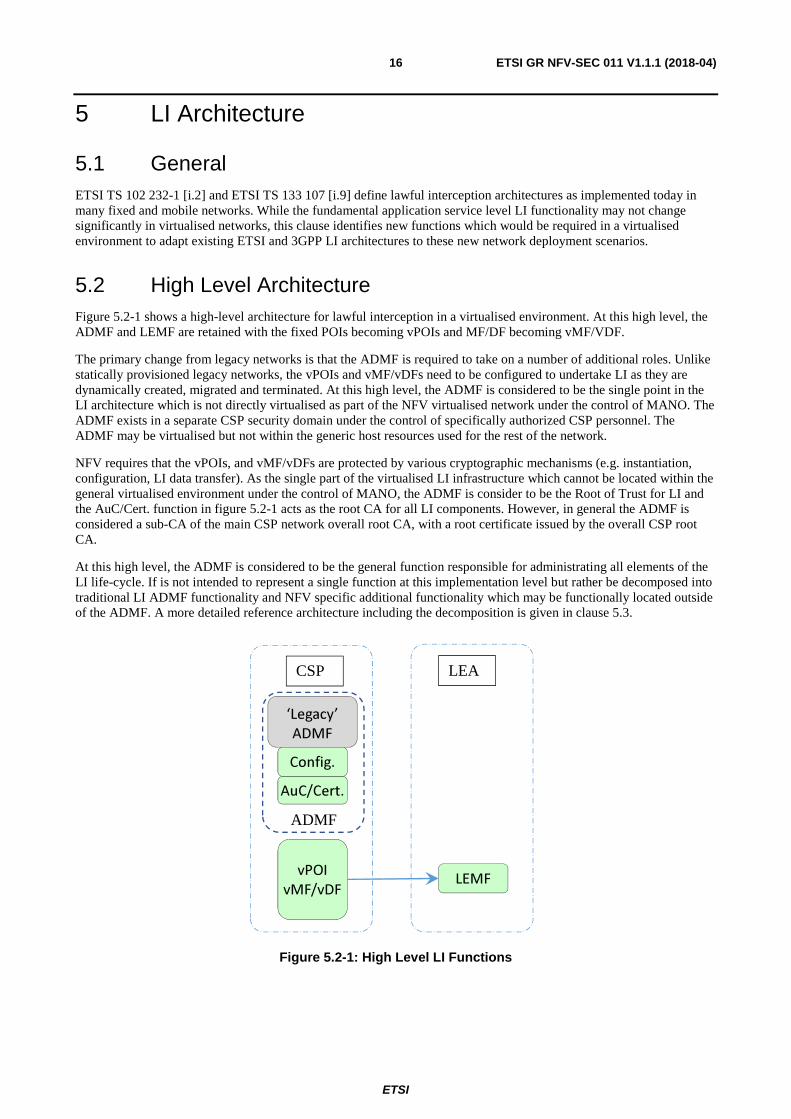
5.2 High Level Architecture Figure 5.2-1 shows a high-level architecture for lawful interception in a virtualised environment. At this high level, the ADMF and LEMF are retained with the fixed POIs becoming vPOIs and MF/DF becoming vMF/VDF.
The primary change from legacy networks is that the ADMF is required to take on a number of additional roles. Unlike statically provisioned legacy networks, the vPOIs and vMF/vDFs need to be configured to undertake LI as they are dynamically created, migrated and terminated. At this high level, the ADMF is considered to be the single point in the LI architecture which is not directly virtualised as part of the NFV virtualised network under the control of MANO. The ADMF exists in a separate CSP security domain under the control of specifically authorized CSP personnel. The ADMF may be virtualised but not within the generic host resources used for the rest of the network.
NFV requires that the vPOIs, and vMF/vDFs are protected by various cryptographic mechanisms (e.g. instantiation, configuration, LI data transfer). As the single part of the virtualised LI infrastructure which cannot be located within the general virtualised environment under the control of MANO, the ADMF is consider to be the Root of Trust for LI and the AuC/Cert. function in figure 5.2-1 acts as the root CA for all LI components. However, in general the ADMF is considered a sub-CA of the main CSP network overall root CA, with a root certificate issued by the overall CSP root CA.
At this high level, the ADMF is considered to be the general function responsible for administrating all elements of the LI life-cycle. If is not intended to represent a single function at this implementation level but rather be decomposed into traditional LI ADMF functionality and NFV specific additional functionality which may be functionally located outside of the ADMF. A more detailed reference architecture including the decomposition is given in clause 5.3.
Figure 5.2-1: High Level LI Functions
‘Legacy’
ADMF
AuC/Cert.
Config.
vPOI vMF/vDF
LEMF
CSP LEA
ADMF

ETSI
ETSI GR NFV-SEC 011 V1.1.1 (2018-04)17
5.3 Reference Point Architecture Figure 5.3-1 defines the reference architecture for LI in an NFV environment. This reference architecture is used as the basis for LI solution approaches described in clauses 6 and 7.
Figure 5.3-1: Virtualised LI Reference Architecture
While lawful interception requires a number of specialist subscriber traffic isolation, capture and delivery capabilities, combined with a very tightly controlled security access/visibility requirements, LI is in many ways just a special case of fraud and security monitoring. As such LI has many things in common with the capabilities described in ETSI GS NFV-SEC 013 [i.8]. Therefore, the LI reference architecture re-uses LI specific instances of some ETSI GS NFV-SEC 013 [i.8] functionalities in order to instantiate and control LI functionality.
The LI Controller performs a similar role to the security controller in SEC 013 and the Sc-Or/Sc-Vnfm/Sc-Vi interfaces would share the same basis protocols as the ORCH-LI/VNFM-LI/VIM-LI interfaces. However, while they perform similar functions the LI NFV functions and interfaces have much more stringent security separation, visibility and access requirements, so while they share some elements of basic architecture they are entirely separate capabilities.
As decomposed from figure 5.2-1, the "Virtualised Network" in figure 5.3-1 represents the functions which exist in the virtualised network service domain (e.g. the 3GPP network functions and services). While these VNFs (applications) are outside the scope of NFV, it is important to identify the interfaces and functions which the application layer LI functions will require in order to control and instantiate LI at the NFV layer. The "ETSI NFV" box in figure 5.3-1 represents those LI elements/functionalities that exist at the NFV layer.
As discussed in clause 5.2, the ADMF cannot exist inside the general host environment under the control of MANO. However, in order to instantiate, configure, locate, scale and control NFV based virtualised LI components (e.g. vPOIs and MF/DF), elements of the ADMF from figure 5.2-1 would need to exist within the MANO domain.
VNF with
Virtual
POI or POI
as VNFI
MANO ORCH-LI
VNFM-LI
VIM-LI
Li-Os-1
Ve-Vnfm
Nf-Vi
LI CONTROLLER
MF/DF2 VNF
MF/DF3 VNF
VNFM
VIM
ORCH
NFVI
(vMF3/ vDF3)
VNFCI
(vPOI) VNFCI /
VNFI
(vMF2/ vDF2)
VNFCI
LEMF
X1-LRPG
HI-1 HI-2
HI-3
Virtual Handove
r HI-1 HI-2
HI-3
Handover LRPG
X1-1 (configure targets) X0-1 (configure vPoI)
X1-2 (configure targets) X0-2 (configure vMF2/DF2)
X1-3 (configure targets) X0-3 (configure vMF3/DF3)
LI-ADMF X2
X1-
X3 X1-
vPOI
vMF2/vDF2
vMF3/vDF3

ETSI
ETSI GR NFV-SEC 011 V1.1.1 (2018-04)18
The role of the LI Controller (as described in clause 6.6) is to provide the interface between the ADMF (responsible for application layer LI target configuration and administration) and MANO. The LI Controller is responsible for interacting with MANO to monitor VNFI creation, modification and termination events to ensure that vPOIs are maintained in the correct places in the virtualised network. The LI Controller effectively provides the additional administration functionality required to allow the ADMF to manage LI targeting at the application layer in a near identical way to legacy networks. In this way, it should also be possible to allow virtualised and non-virtualised LI system functions to co-exist in a single unified LI implementation.
The LRPG in figure 5.3-1 is used to provide an HI proxy function to isolate the LEMF and downstream handover network connections from visibility at the MANO or SDN level. The LRPG is further described in clause 6.5.
Clause 6 describes the roles of each of the functions in figure 5.3-1 in more detail.
6 LI Deployment Scenarios
6.1 General This clause describes a number of LI architectures intended to address different deployment scenarios. As with legacy deployments running complex services based on SIP or those implementing encryption, solutions using embedded LI functionality contained within the VNFIs considered to be the default approach. Only in scenarios where embedded LI functionality is not available (e.g. not implemented by the vendor or not practical due to security or other operational restrictions) should non-embedded LI approaches be considered. The alternatives such as "off-switch" (e.g. software or hardware DPI) are likely to be inferior to embedded LI functionality and extremely fragile under VNF mobility or scaling conditions.
The architecture in clause 6.2 describes the "POI VNF Embedded" solution which when implemented in conjunction with security mechanisms in ETSI GS NFV-SEC 012 [i.7], most closely provides an equivalent level of LI capability and security to that of an "on-switch" legacy hardware implementation. Such an implementation should address most national security requirements.
Where the physical security of the hardware platform cannot be guaranteed or security requirements in ETSI GS NFV-SEC 012 [i.7] cannot be fully met, clause 6.3 provides a modified architecture based on clause 6.2 which reduces but does not fully mitigate the security risks. However, clause 6.2 should still be used where possible. Clause 6.3 is considered an adjunct to and included in the POI VNF Embedded case.
Where embedded LI within the VNF is not available or the VNF implementation is not trusted (e.g. because of weak security or unverified code), clause 6.4 provides architecture approaches for POI VNF external LI. However, these "POI VNF external" cases may cause significant overhead or NFV configuration restrictions. Furthermore, as with legacy networks, in scenarios where the VNF contains SIP or other internal state machines which are not directly reconcilable from the VNF's external interfaces, these architectural approaches may not be sufficient to meet regulatory requirements.

ETSI
ETSI GR NFV-SEC 011 V1.1.1 (2018-04)19
6.2 POI VNF Embedded - Trusted VNF
6.2.1 Reference Diagram
Figure 6.2.1-1: Simplified High Level Trusted Virtualised LI Architecture
The figure is intended to explain the role of the LI controller as composed by two management functions at application level and at NFV level with a different logical interface at each level. A more detailed explaining of each function and interface in figure 6.2.1-1 is given in clause 6.2.2.
The LI application level controller is considered an addition to LI admin functions together with ADMF already defined in existing ETSI TC LI and 3GPP specifications. It, therefore, belongs to LI application domain. The two functions are kept separate to leave open the possibility to implement and deploy them in different ways in NFV.
The MANO and/or SO (Security Orchestrator) are shown in figure 6.2.1-1 in a simplified form indicated by the dotted box. These interfaces are given in more detail in figure 5.3-1 and are based on re-use of the security monitoring interfaces provided by ETSI GS NFV-SEC 013 [i.8].
HI1
HI2, HI3
Li-Os-1
X1_1 (Conf targets)
Admin Functions
VNF
vPOI
LI NFV controller
vMF / vDF
X1_2 X1_3
Warrant Issuing
Authority
HI1
MANO
or SO
X0_1 (Conf POI App Params)
(Conf/ Audit VNF Security)
ADMF
LI App Controller
X1_DC
LI-Os-0
HI2, HI3 X2, X3
X0_2
LRPG
LEMF

ETSI
ETSI GR NFV-SEC 011 V1.1.1 (2018-04)20
6.2.2 Components and Interfaces description
Table 6.2.2-1
Components Name Description
VNF Virtualised Network Function as from ETSI GS NFV 002 [i.5]. vPOI In the "POI VNF Embedded" scenario the vPOI is an internal interception
function (as described in ETSI TS 133 108 [i.6]) embedded in the VNF application.
LI Controller Create, Modify, Delete, Audit the vPOI and vMF/vDF vPOI configuration during their lifecycle. It does not handle LI target administration. Two sub-functions: LI controller at network service application level:
• Activate, configure and audit the configuration of vPOI and/or vMF/vDF (e.g. configure certificates for SSL, modify triggering option and apply national parameter).
• Notify ADMF the node is ready for configuration for interception. • Act as LI root of trust at application level (e.g. maintaining/verifying
vPOI certificates/keys secure copy). LI controller at NFV level:
• Check if LI needed for a VNF according to the policy communicated by ADMF (LI App controller part).
• Enforce and maintain LI VM /VNF security constraints configuration via MANO and/or SO security support.
• Audit security of LI vPOI and vMF/vDF (via SO or MANO functions), (see note).
ADMF In addition to legacy functions defined in ETSI and 3GPP LI specifications: • Keep track of dynamic creation, modification, termination of vPOIs
and their types (e.g. vCSCF, vSBG, vEPG etc.), vMF/vDF and network topology. It is expected to be updated by notification from LI NFV controller.
• Execute the warrant request according to the latest vPOI VNF type and network topology.
• Order audit of secure configuration of the vPOI application configuration to LI app controller and of the VNF level security to the LI NFV controller.
• Act as the root key and certificate authority (CA) for all other LI functions and components.
vMF/vDF Legacy definition applies. MF and DF may also be implemented as per legacy non-virtualised model. The virtualised vMF and vDF will bring the need of related VNFs lifecycle management while providing the benefit of scaling over NFV resources. Additional interface can be required to coordinate management of vMF/vDF with other entities in the diagram. This is for further specification.
LRPG This is a new function as described in clause 6.5 with the primary purpose of proxying the LEMF from MANO, SDN controller or other CSP personnel not authorized to know about LI. This function is optional but without it in full NFV network/SDN scenarios the LEMF will be visible to MANO and the SDN controllers.
LEMF Legacy definition applies. Extensions to HI will be required to address NFV security issues and transfer additional data/information generated by NFV networks.
Warrant Issuing Authority Legacy definition applies. NOTE: LI controller at NFV level is not intended to replicate any NFV management and security
orchestrator functions but to reuse a dedicated separate LI interface instance to these underlying NFV capabilities, which have been implemented to meet LI security requirements.

ETSI
ETSI GR NFV-SEC 011 V1.1.1 (2018-04)21
Table 6.2.2-2
Interfaces Name Description
LI-Os-0 Between LI App Controller and ADMF: • Used to exchange New/Changed LI function (vPOI and vMF/vDF)
Info and LI VNFI/VNFCI configuration parameters. See note 1.
LI-Os-1 From LI NFV ctrl to ADMF functions: • Info/notification about new/changed/delete VNFI (with vPOI), its type
(e.g. CSCF, SBG) and LI initial connection parameters details. • VNF security Audit result.
From ADMF to LI NFV Ctrl: • request to secure VNFI (e.g. via security policy and geo location
constraints, etc.), (see note 2). • audit VNFI security at any time.
NFV level I/F Conf VNF security
Uses interfaces given in figure 5.3-1 (ORCH-LI/VNFM-LI/VIM-LI). From LI controller to MANO/SO:
• Instrument security setup (trusted platform, geo loc, resource constraints, etc.) to MANO or SO for the VNFI containing the vPOI.
• Audit of VNFI security constraints requests. From MANO/SO to LI controller:
• Info/Notification a new VNF instantiation. • VNF security constraints audit result.
X0_1, X0_2 From LI App controller to vPOI and vMF/vDF: • Configure/view LI application parameters (LI activation, deactivation,
SSL keys setup, national options selection, etc.). • Audit LI parameters configuration.
From vPOI and vMF/vDF to LI app controller: • Initial connection establishment of a new unconfigured
vPOI/vMF/vDF to the LI controller. • LI application logs/alarms about configuration parameters
anomalies. • Configuration parameters audit response.
HI1, HI2, HI3 These have the basic functionality of existing legacy HI interfaces defined in ETSI TS 133 108 [i.6] and ETSI 102 232-1 [i.2] but with additional security mechanisms/transport protocol and data elements required to support NFV deployments.
X1 including X1_1, X1_2 and X1_3 These have the basic functionality of existing legacy X interfaces defined in ETSI TS 133 108 [i.6] and ETSI 102 232-1 [i.2] but with additional security mechanism s/ transport protocol and data elements required to support NFV deployments.
X2 and X3 These have the basic functionality of existing legacy X interfaces defined in ETSI TS 133 108 [i.6] and ETSI 102 232-1 [i.2] but with additional security mechanisms/transport protocol and data elements required to support NFV deployments.
X1_DC Used by the vPOI and vMF/vDF to inform each other of changes (e.g. scaling or mobility) in the NFV environment.
NOTE 1: Interface may be internal or external depending on whether the ADMF and LI App Controller are implemented as a separated or combined function.
NOTE 2: A basic security policy could the VNFI type (e.g. vCSCF, vMME, vEPG) which are expected to contain a vPOI function.
6.3 POI VNF Embedded - Low-Trust VNF
6.3.1 Reference Diagram
In some specific deployment scenarios, it may not be possible to achieve sufficient physical, software or hardware security (e.g. Femto Cell, eNB or other edge network locations such as ETSI ISG MEC scenarios) to allow LI to be implemented as per clause 6.2. Where there is significant risk that the VNF may be compromised or hardware physical accessed/stolen, the architecture in figure 6.3.1-1 can be used to reduce the impact of a compromise.

ETSI
ETSI GR NFV-SEC 011 V1.1.1 (2018-04)22
While this architecture decreases security risk in Low-Trust deployment scenarios, the Triggering Control Function (TCF) introduces triggering delays and may place significant restrictions on VNF mobility and routing configurations. In addition, since the VNF containing the vPOI is not fully trusted it is unlikely to meet fully normal LI national security requirements.
Therefore, the Trusted VNF architecture in clause 6.2 should always be used where possible.
Figure 6.3.1-1: Simplified High-Level Low-Trust Virtualised LI Architecture
In figure 6.3.1-1, the full target list is provided to the Triggering Control Function (TCF) over the X1_1T interface by the Admin Function. However, the full target list is not provided to the vPOI. Instead the vPOI intercepts all trigger signalling information for all communications and passes it to the TCF for processing via the XT interface. The TCF identifies matches between the LI target list and the signalling received from the vPOI. The TCF then instructs the vPOI to intercept specific sessions.
The LRPG in figure 6.2.1-1 is not shown in figure 6.3.1-1 but it is also considered to be in scope for the low trust scenario.
In this scenario, the TCF and MF/DF can be either virtualised or implemented in standalone hardware but in either case should be located in a secure location which fully meets LI security requirements.
6.3.2 Components and Interfaces description
The Components and Interfaces for the low trust scenario are the same as the descriptions in clause 6.2.2, except where they are specific to the low trust scenario and are described in this clause.
Li-Os-1
HI2, HI3
Admin Functions
VNF vPOI
LI NFV controller
vMF / vDF LEMF
X1_2 X1_3
X2, X3
Warrant Issuing
Authority
HI1
MANO
or SO
X0_1 (Conf PoI App Params)
(Conf/ Audit VNF Security)
ADMF
LI App Controller
X1_DC
LI-Os-0
TCF X1_1T (Conf targets)
XT X1_1P
X0_2

ETSI
ETSI GR NFV-SEC 011 V1.1.1 (2018-04)23
Table 6.3.2-1
Components Name Description
vPOI In the "POI VNF Embedded - Low Trust" scenario the vPOI is an internal interception function embedded in the VNF application but it is not "trustworthy" enough to contain all LI sensitive information (e.g. target list). The vPOI receives instructions on what and when to intercept from the TCF.
TCF The TCF is an LI specific VNF which fully meets LI security requirements for holding and processing sensitive LI information (e.g. target lists). The TCF is provisioned with the full target list by the ADMF (or at least that portion of the target list applicable for the vPOI(s) it is managing). The TCF is responsible for processing signalling session information for all communications visible to the VNFI in which the vPOI is embedded. The TCF is responsible for identifying which communications match and target list provided by the ADMF. The TCF is responsible for informing the vPOI to start, and stop intercepting specific communications and handing them over as per the trusted scenario in clause 6.2.
Table 6.3.2-2
Interfaces Name Description
X1_1T This interface is equivalent of X1_1 in clause 6.2.2. The X1_1T is used by the ADMF to provide the TCF with target list and other information required to perform and maintain interception.
X1_1P This interface is used by the TCF to provide the vPOI with specific service and /or communications stream targeting instructions.
XT This interface is used by the vPOI to provide the TCF with a copy of all signalling or other service access control information for all communications visible to the vPOI.
6.4 Non VNF Embedded POI
6.4.1 General
The architectural approaches described in clauses 6.2 and 6.3 are only two approaches which guarantee application layer state awareness and are in theory highly resilient to network changes and VNF mobility. However, there are situations where LI is required but either the VNF does not natively provide evidential grade LI which is able to meet national regulations or the VNF provides no LI capability at all. Obviously in these scenarios it would be better to pick an alternative VNF vendor or request the VNF vendor to provide embedded LI but nevertheless non-embedded LI may be required.
Non-embedded POIs have a number of major limitations. Firstly being external they can only operate using communications content and metadata that is available external to the targeted VNF. VNFs may implement Span ports or similar monitoring ports for external POIs but these tend to be unreliable if the VNF is under high service load (legacy span ports tend to be low CPU priority). Alternatively, they are limited to utilizing the communications links around a VNF and are therefore limited by any encryption being applied to those links and cannot recreate the internal state machines of the application layer VNF functions (especially difficult for SIP proxies or similar functions).
For NFV, logically an embedded vPOI will move and scale automatically with the VNF into which it is embedded. For external POIs considerably more effort is required to maintain the POIs in the correct places or 100 000 s+ redundant POIs need to be scatter across the network into every location that a POI might be needed. That is inefficient and presents a number of operational security challenges to maintain them.
Combined with the effects of high VNF mobility, network scaling and network slicing, the approaches in this clause should be avoided unless otherwise unavoidable. However, for small scale deployments, limited life time specialist VNF deployments (e.g. in association with a sports event or other temporary scenario) or in tactical scenarios then approaches in this clause may be tolerable.

ETSI
ETSI GR NFV-SEC 011 V1.1.1 (2018-04)24
6.4.2 Non-Embedded POI
Figure 6.4.2-1 represents the non-embedded vPOI scenario, where a vPOI implemented as a separate LI VNF is used to perform LI for another VNF (represented as "Target VNF"). The thick red dashed line in figure 6.4.2-1 (labelled as "Span Port or VNF Traffic links"), represents both the scenario where a specific LI assistance Span (copy) port is used to pass data to the vPOI for all traffic to or from the target VNF or where the vPOI has been configured to tap the communications links around the target VNF. The Span port in this scenario could also be provided by a vSwitch or vRouter rather than directly from the VNF.
The target VNF is not explicitly aware of the operation or presence of the vPOI, except to the extent that it may be required to provide encryption keys in order for the vPOI to inspect communication links over which the target VNF communicates with other entities.
Figure 6.4.2-1: Simplified High-Level Non-Embedded POI Virtualised LI Architecture
In this scenario, it may be possible to automate vPOI placement by grouping the vPOI VNF with the target VNF at the MANO software catalogue and VIM level so that MANO will automatically instantiate and maintain the vPOI in the correct places. However, this may expose the presence or association of the vPOI to the target VNF. Where that is not acceptable, the LI controller will need to request real-time instantiation of the vPOI by MANO and be responsible for requesting changes to maintain the associations of vPOI to target VNF under VNF mobility or scaling scenarios.
6.4.3 NFV Layer POI
The alternative to the approach in clause 6.4.2 is to perform LI at the NFV layer. This is similar to the use of NFV level security monitoring agents in ETSI GS NFV-SEC 013 [i.8]. LI at the NFV layer can also include other NFVI layer capabilities (e.g. VSwitch). For LI, these "LI Agents" would need to be created in appropriate places either statically or dynamically throughout the NFV infrastructure. These LI Agents would be logically simpler and more generic than the application layer vPOIs in clause 6.4.2.
Li-Os-1
HI2, HI3
Admin Functions Target VNF
LI NFV controller
vMF / vDF LEMF
X1_2 X1_3
X2, X3
Warrant Issuing
Authority
HI1
MANO
or SO
X0_1 (Conf PoI App Params)
(Conf/ Audit VNF Security)
ADMF
LI App Controller
X1_DC
LI-Os-0
vPOI (POI as a VNF)
Span Port or VNF Traffic links
X1_1
X0_2

ETSI
ETSI GR NFV-SEC 011 V1.1.1 (2018-04)25
Logically an NFV layer POI would not be application service aware. These POI would have an LI X interface equivalent to that of application layer VNF POIs under the control of the ADMF. So, while such LI Agents may be able to tap internal VNFI connectivity or access other infrastructure layer data that would not be available to a VNF vPOI, their ability to target application layer identities or services in an intelligent manner would likely be limited. The LI controller and/or vMF/vDF would need to do considerable application layer service processing in order to interpret data coming from the LI Agents at the NFV layer and provide the correct target selectors to the LI Agents. Whereas security monitoring agents in ETSI GS NFV-SEC 013 [i.8] monitor all communications against limited fixed selectors, LI needs to use dynamic selectors against limited specific target communications, which is considerably more difficult.
Therefore, as with the non-embedded vPOI approach in clause 6.4.2, while this approach is a useful capability to have in the toolset for LI, its applicability and usefulness is considered limited and only suitable for limited scenarios. Solutions in clauses 6.2 and 6.3 should be used except where impractical.
6.4.4 NFV External Hardware POI
In NFV networks it is still theoretically possible to use external legacy hardware probes or other capabilities to perform LI external to the NFV environment. While this is possible, the static nature of this hardware approach would be overtly visible to the SDN controller and/or MANO. Where VNF mobility is high they may also cause significant traffic tromboning or result in other undesirable impacts on the NFV system. This approach also suffers to a similar extent to solution approaches in clauses 6.4.2 and 6.4.3 in terms of access to internal VNF state and encryption, etc.
There may still be a place for such solutions in the short term especially where the external probes contain specialist acceleration or data crunching hardware which is not easy to replicate in an NFV environment.
6.5 LI Routing Proxy Gateway
6.5.1 General
As discussed in clause 4, in a full NFV and SDN only network, all network interconnections and functionality need to be visible to MANO and the SDN controller in order for functions to communicate with each other or identities external to the NFV network. As such the LEMF should have an overt visible end point address. This is likely to be problematic for some LEAs.
Therefore, where required, an NFV implementation would include 1 or more LI Routing Proxy Gateways (LRPGs), as shows figure 5.3-1.
6.5.2 LRPG Functionality
The LRPG is responsible for hiding the LEMF end point addresses and routing information from the overt NFV network which is not authorized to know about LI. The LRPG is placed at the edge of the NFV network/SDN where a physical hidden secure connection to the LEMF can be implemented or when a dedicated LI SDN cloud connection can be established which does not need to be visible to the CSP NFV network/SDN.
As a minimum, the LRPG would need to be able to support the following set of functionalities, although not all of them would be needed in any particular scenario:
• Provide a mapping between less sensitive LI routing identity (e.g. Special LRPG routing code) and the real LEMF end point. This may need to be configurable on a per warrant and/or per LEMF basis.
• Act as a forwarding proxy from the DF to the LEMF.
• Provide HI2/3 protocol conversion between NFV HI2/3 and Legacy HI2/3 connections from the DFs. (e.g. LEMF only supports legacy handover). A loss of information may occur converting NFV HI2/3 to legacy HI2/3.
• Provide inbound hiding for HI1 from the LEA side to the ADMF (this is not specifically covered in the present document).
• Provide HI2/3 combination into a single connection for multiple vMFs/vDFs and/or MFs/DFs (this may also require protocol conversion of legacy to NFV in mixed scenarios).

ETSI
ETSI GR NFV-SEC 011 V1.1.1 (2018-04)26
• Provide mapping between less sensitive LI routing identity in low trust scenarios (e.g. clause 6.4), where vPOI, TCF, vMF or vDF are not trusted with real LEMF routing identities.
• Provide removal of padding data used on the HI2/3 interfaces to obscure LI data exchanges within the NFV and SDN environments.
6.6 LI Controller
6.6.1 Overview
The LI controller is responsible for managing the instantiation and lifecycle of LI VNFCIs through interaction with MANO. The LI controller is composed of two logical functional entities which can be kept separate or combined in different implementations, depending on the type of service, network, POI, vPOI, interception tools used and legacy nodes present. The description in this clause considers a generic approach.
6.6.2 LI Controller Functions
6.6.2.1 The LI Service Controller
The LI service controller is responsible for the overall configuration and audit of a virtualised LI in NFV. By default, this functionality is an NFV service level extension of the existing ADMF in legacy networks. In legacy networks, the configuration of LI functions is undertaken through non-real-time manual static provisioning. In a virtualised network the LI service controller is responsible for real-time automation of that manual legacy step.
In addition, the LI service controller can act as a root of trust at application level for all the LI sensitive information encryption and integrity overlaying the infrastructure provided security support. The LI service controller as part of the ADMF is responsible for configuring policies and rules used by the LI Security Controller using the LI-OS-1 interface.
In all LI scenarios, the ADMF is the "master" LI function in a network. The LI security controller is subject to control from the LI service controller and where the LI service controller is not embedded within the ADMF, it is subject to control from the ADMF.
6.6.2.2 The LI Security Controller
The LI security controller (also known as "LI NFV controller"), is responsible for the NFV level interactions with MANO which are required to instantiate an LI VNFI (vPOI or vMF/vDF etc.) and manage the real-time lifecycle of that LI VNFCI, so that the LI Service Controller in the ADMF at the application level can configured and maintain interception of the virtualised network or service.
It is responsible for ensuring the integrity of instantiated LI VNFCIs, correct allocation of secure execution resources and for enabling secure communication with the ADMF to allow service level configuration of the LI function. The LI security controller is managed by the LI service controller via the LI-OS-1 interface.
6.7 LEMF
6.7.1 General
From the perspective of standardization, the definition and functionality of the Law Enforcement Monitoring Function (LEMF) has traditionally been considered an out of scope black box to which intercepted communications are delivered. The arrival of NFV will have significant implications for the LEMF. Therefore, this clause highlights the issues that LEAs will need to address when implementing LEMFs that receive intercepted traffic from NFV network. However, solving these issues and any LEMF standardization is outside the scope of the present document.

ETSI
ETSI GR NFV-SEC 011 V1.1.1 (2018-04)27
6.7.2 Virtualisation (vLEMF)
Given the advantages of virtualisation, it may be desirable to consider virtualisation of the LEMF into a vLEMF. Such virtualisation would obviously occur within the domain of the LEA. As with consideration of virtualisation of the ADMF in the CSP network, using an isolated NFV environment within the LEA provides flexibility which is not possible in legacy architectures. For national security reasons, it is unlikely to be appropriate to virtualise the LEMF as an extension of the CSP NFV platform.
Given that the CSP NFV network can scale and change dynamically (as discussed further in clause 6.7.3), the LEMF needs to be able to also adapt accordingly. It would also allow for new LEMF capabilities, to provide interception support for new or temporary CSP services without the need to upgrade the LEA's entire legacy LEMF.
6.7.3 Scaling and Dynamic Configuration
One of the core advantages of virtualisation for the CSPs is that it allows a given amount of fixed common hardware to be rapidly repurposed to meet dynamic geographical or service type needs. This means that the voice capacity of an NFV network can be significantly increased for a few hours and then quickly scaled back to allow reuse of resources for video or messaging services.
With a legacy LEMF model, the LEMF would need to be scaled to be able handle the maximum capacity for all of the CSP service combinations in parallel to guarantee that the LEMF is able to always handle the volume of intercepted traffic being delivered to the LEA.
A vLEMF could dynamically match changes in CSP NFV network configuration by either be passively adapting to the profile (service type mix and pattern) of the intercepted traffic delivered to the vLEMF or through specific CSP provided scaling configuration data.
6.7.4 Single logical vLEMF
Another consequence of NFV (and likely 5G), is the ability to use multiple services, multiple operators, network slices or access technologies as part of a single user communication. Therefore, an LEMF will need to be able to span all access technologies and all possible CSPs involved in a user communication, to ensure that the LEMF is able to correlate and reconstruct all intercepted communications.
7 Part VNF Part Legacy Implementations
7.1 Overview Part virtualised, part legacy hybrid networks, represent a significant challenge for LI, both in terms of identifying and correlating target traffic, and in terms of security of both the virtualised LI and legacy LI capabilities. For the foreseeable future, such hybrid deployments will be increasingly common as CSPs slowly transition to full NFV network deployments.
The relative meaning of intercepted information may be impacted by the route target traffic takes through the hybrid network.
While it is possible to envisage two entirely separate legacy and virtualised LI solutions, to ensure correlated reconstruction of target traffic at the LEMF, any LI solution will need to span both the legacy and virtualised elements of a hybrid network deployment.

ETSI
ETSI GR NFV-SEC 011 V1.1.1 (2018-04)28
The following non-exhaustive scenarios need to be considered:
Table 7.1-1: List of example legacy and VNF LI scenarios
Scenario Legacy non-LI
function
Standalone ADMF
Standalone MF/DF
Legacy POI
Virtualised non-LI
function
Virtualised
ADMF
Virtualised POI
Virtualised
MF/DF
VNF Mobility
(LI and/or non-LI VNFs)
Grouped to Stage
x
1 X X X X X 0 2 X X X X 0 3 X X X X 1 4 X X X X X 2 5 X X X X 2 6 X X X 3 7 X X X X 3 8 X X X X X 3 9 X X X X X X 3 10 X X X X 3 11 X X X X X X 1 12 X X X X X 1 13 X X X X X 2 14 X X X X X X 2 15 X X X X X 2 16 X X X X 3 17 X X X X X 3 18 X X X X X X 3 19 X X X X X X X 3 20 X X X X X 3 21 X X X X X 4 22 X X X X X X 4 NOTE 1: X in table 7.1-1 indicates the inclusion of a node/mobility behaviour in a scenario. NOTE 2: Grouped to Stage X (0-4) in table 7.1-1 corresponds to the evolution stages described in clause 8.2.
7.2 General Implications
7.2.1 ADMF
7.2.1.1 Backward compatibility
In order to perform LI on a full NFV or part NFV network (where 1 or more POIs is virtualised), the ADMF should be upgraded or replaced in order to support NFV. Therefore, the ADMF cannot be a Legacy non-NFV aware ADMF.
7.2.1.2 Standalone vs NFV Virtualised
The ADMF is considered functionally independent to the target subscriber network service and real-time interception performed at the POIs. Therefore, from a functionality perspective it makes no difference whether the ADMF is NFV virtualised or standalone hardware.
From a security perspective, the ADMF is the root of trust and central point of control for all interceptions. Therefore, from a security perspective it is recommended to implement the ADMF in standalone hardware which is fully separated from the NFV platform hosting the vPOIs.

ETSI
ETSI GR NFV-SEC 011 V1.1.1 (2018-04)29
7.2.2 MF/DF
7.2.2.1 Backward compatibility
In order to perform LI on a full NFV or part NFV network (where 1 or more POIs is virtualised), the MF/DF should be upgraded or replaced in order to support NFV. Therefore, the MF/DF cannot be a Legacy non-NFV aware MF/DF.
7.2.2.2 Standalone vs NFV Virtualised
Unlike the ADMF, the MF/DF needs to be able to handle real time target traffic, adapt and scale according to network service VNFI changes. Therefore, while from a security of the MF/DF perspective it may be desirable to place the MF/DFs outside of the NFV domain, unlike the ADMF this has more serious architectural/SDN impacts.
If the MF/DFs are virtualised (vMF/vDF) then they can grow, shrink or multiply in line with changing network conditions. While this may make life more difficult for the LEMF as the number and identification of the vMF/vDFs would become dynamic, it makes performing interception in an NFV environment easier. vMF/vDFs can be placed in or close to the vPOIs minimizing timing/correlation issues and they can move with the vPOIs. This removes the need to trombone large volumes of intercepted target traffic from vPOIs to fixed MF/DFs as the vPOIs move. New vMF/vDF capabilities are also easier to deploy as these could be bundled with new service VNF deployments. vMF/vDFs could even be user service specific.
If the MF/DFs are not virtualised, firstly they need to be scaled to meet the worse cause traffic routing and LI traffic volume scaling scenarios, with capacity for future network enhancements. Secondly the SDN routing needs to cope with the vPOIs moving randomly with respect to the fixed MF/DFs and then the SDN needs to trombone LI target traffic to the MF/DF. Assuming the initial volume of LI target traffic is much higher in many scenarios before it passes through the MF/DF (e.g. de-duplication) then, hiding the LI traffic is more difficult than for a distributed virtualised MF/DF scenario.
Furthermore, it is possible to consider scenarios where only part of MF/DF are virtualised as specific NFVIs or combined in as a VNFCI with the vPOIs. In these scenarios, the final HI2/HI3 links to the LEMF would originate from outside of the NFV domain but all of the capture, filtering, correlation and formatting would occur within the NFV domain optimized to the network service/mobile topology. Such scenarios will require changes or extensions to existing ETSI TC LI interception and handover models.
Therefore, choice of virtualised or non-virtualised MF/DF deployment, scaling and routing is likely to be implementation specific. However, placing the MF/DFs in the NFV domain with vPOIs is likely to be more efficient from an NFV scaling and SDN bandwidth perspective. Furthermore, if the security risks can be mitigated for the vPOIs as per ETSI GS NFV-SEC 012 [i.7], then the security risks of implementing the MF/DFs as VNFIs can also likely be mitigated.
7.2.2.3 Handover Aspects
As noted in clause 7.2.2.2, where vMFs/vDFs are used then a new version of the ETSI TC LI HI2/HI3 interfaces will be required to provide adequate security in an NFV environment. If external legacy hardware MFs/DFs are used then the security problem still exists on the X2 and X3 interfaces.
In a mixed NFV implement, it is reasonable to assume that vPOIs may be paired with vMF/vDFs and legacy POIs will be paired with legacy MFs/DFs especially where NFV has been deployed for new technologies (e.g. 5G) and the legacy networks have not been upgraded. In this scenario, there will be two different variations of the HI2/HI3 interfaces which are implementing with potentially different interface or security protocol. LEMFs will need to be able to deal with correlation and session reconstruction across both legacy and virtualised MF/DF HI2/3 source connections, especially where target mobility results in LI being generated from both MF/DF and vMF/vDF for a single interception session.
The LRPG as described in clause 6.5, provides some mitigation to the issues highlighted in this sub-clause but does not entirely mitigate the impacts of mixed legacy and virtualised handover.

ETSI
ETSI GR NFV-SEC 011 V1.1.1 (2018-04)30
7.2.3 Mixed Legacy and Virtualised Functions
In a legacy network, the LEMF derives much of the meaning of IRIs received from the network by the implicit physical relationships between parameters in the IRI. For example, the local dial code in PSTN or components of a CELLID provide some indication as to where equipment is physically located. In full NFV networks, while the meanings of some parameters may change or become dynamic using alternative parameters, again the LEMF can in general implicitly determine their meaning providing it knows the ruleset governing the dynamic parameters.
In a hybrid network, the meaning and expected parameters delivered in IRIs may change according to whether the POI was a legacy physical POI or a vPOI. The bigger issue is what happens when different non-LI nodes are virtualised or change between virtualised and non-virtualised nodes during an intercepted communication. For a vPOI, it may be possible to compensate by reporting extra information to the MF/DF or LEMF to allow any changes to be explicitly highlighted in the information sent to the LEMF. For a legacy POI, it is unlikely to be able to provide any additional information relating to virtualised or dynamic network state around it.
If X2/X3 or HI2/HI3 need to be enhanced to support NFV (URI based delivery, additional encryption, obfuscation padding or additional parameters), then the LEMF is likely to receive multiple streams in both the old and new forms for different intercepted communications or at different times during a single intercepted communication.
Assuming that for evidential integrity reasons the LEMF wants to be able to confirm a given VNFI is correctly located in a given legal jurisdiction or wants to be able to query what type a given vPOI is then, the LEMF would need to query the ADMF or be told periodically by the ADMF. However, if the nodes are part legacy and part virtualised, it may be very difficult for the LEMF to determine whether a given LI stream has originated from a legacy or vPOI, or whether key wider parts of the network where physical or virtual at any given point. This is likely a bigger problem for post event forensics.
This may be even more complicated from a retained data perspective and require the ADMF to retain detailed service level network state information. It is unclear from where such information could be reliably obtained in hybrid scenarios for pure retained data scenarios where the ADMF is not involved.
7.2.4 VNF Mobility
VNF mobility is in general potentially problematic for LI in terms of correlation, POI setup race conditions and obfuscation. Part legacy part virtualised implementations require the ADMF to maintain a network node and interconnection map from multiple sources in order to maintain or place vPOIs correctly. In full NFV deployments, the ADMF can rely on information from MANO and the SDN controller to understand the current service layer network architecture (see clause 6). In the hybrid case, there is no standardized single information source from which the ADMF obtain node and interconnection information.
Hybrid networks may also require more careful LI backhaul capacity planning. In a full NFV network, while the level of VNF mobility may be higher, the traffic should be fairly uniformly distributed across the data centre estate. In part legacy deployments, LI traffic may concentrate around legacy nodes, which may also place scaling challenges for vPOIs, especially if vPOIs require specialist hardware resources which are in limited supply.
7.2.5 Target Mobility
Physical mobility of the target device within the physical world may or may not have a significant impact on LI. For existing mobile network services, providing the NFV network does not implement VNFs on a per communication basis, with low delay local routing then, it is unlikely that either full or part virtualising an existing service network will significantly impact LI from a target mobility perspective.
In mixed legacy and NFV scenarios the most likely impact is unpredictable correlation behaviour between POI & MF/DFs. If a target moves from one geographic area to another the virtualised functions may well move to minimize traffic routing delays or minimize SDN loading. If all functions are virtualised then behaviour is likely to be predictable in terms of when VNFIs migrate. Similarly, in legacy networks mobility between legacies serving nodes is fairly predictable. In hybrid scenarios, some of the POIs may migrate depending on which are virtualised. This present a challenge LI correlation between legacy and non-legacy POIs.
For future, low delay, high date rate services (e.g. 5G), target mobility is likely to exacerbate mobility impacts of VNF mobility in clause 4.6 of the present document.

ETSI
ETSI GR NFV-SEC 011 V1.1.1 (2018-04)31
7.2.6 LI Security Risks in Hybrid Deployment Scenarios
7.2.6.1 Overview
NFV networks are subject to a much larger range of potential attacks, and attack entry points than well designed legacy networks. In addition, once an attack proves successful, that same attack can potentially be applied to many more VNFI or MANO elements with little or no additional effort. By comparison, legacy hardware networks are in general far more resilient to external attacks as there are more limited points of entry and the physical nature of the network interconnections limits the scope for attacks. However much of the legacy networks security is provided by obscurity rather than good inherent security design (SS7 or X.25 being a good examples).
For NFV to be implemented securely, security mechanisms as detailed in ETSI GS NFV-SEC 012 [i.7] and ETSI GS NFV-SEC 013 [i.8] need to be applied. Combined with secure coding methodologies this makes NFV deployments more intrinsically secure than their legacy counterparts.
However, in real deployments, legacy nodes and VNFI need to co-exist and be interconnected with implicit trust. This implicit trust is required as VNFIs are not supposed to know they have been virtualised. This therefore means that the VNFI are connected to management and service control plane links which include legacy nodes, that do not implement the same level of security as the VNFI.
There are two logical attack models which should be considered for LI; Virtualised Node compromise; Legacy Node compromise.
7.2.6.2 Virtualised Node Compromise
In this scenario, an attacker makes use of a legacy LI node (POI or wider node functionality) or associated signalling to that node, in order to attack an otherwise secure VNFI containing a vPOI. This could be as simple as capturing unencrypted/poorly secured messages sent to legacy nodes and then using these messages to perform attacks on the VNFI. Since the VNFI is required to trust the legacy nodes and communicate with them using legacy protocols, the VNFIs become at risk to bid down, man in the middle, or plain text attacks on the messages/interfaces. Furthermore, an attacker by studying the operation of a legacy node may be able to identity inference attacks against a VNFI of the same type and manufacture (e.g. legacy CSCF vs VNF CSCF).
It is also possible to consider a scenario where an attacker initiates an attack from with the NFV domain which is then allowed to route through legacy nodes (not directly impacting the legacy nodes), which then returns as a trusted message into the NFV domain which does result in an attack.
7.2.6.3 Legacy Node Compromise
In this scenario, an attacker makes use of the VNFIs or hypervisor or associated signalling within the NFV domain to attack legacy nodes which were otherwise previously secure. This could be as simple as the legacy nodes now sharing the same administration domains as VNFIs such that the legacy node operations become more visible to MANO than was possible in the full legacy network. Legacy nodes are unlikely to implement many of the mechanisms an LI VNFCI POI would utilize based on ETSI GS NFV-SEC 012 [i.7]. Therefore, NFV may considerably compromise the security by obscurity protection of legacy POIs. Furthermore, it may be relatively simple to monitor overt events in the NFV domain and then look for corresponding SDN/NFV actions taken by legacy POIs in mixed networks. Furthermore, the physical firewalls and other protection mechanisms around the legacy nodes may be virtualised, considerably increasing the attack exposure surface to those nodes.
It is also possible to consider a scenario where an attacker initiates an attack from within the legacy domain which is then allowed to route through VNFIs (not directly impacting the VNFIs), which then returns as a trusted message into the legacy domain which does result in an attack.
7.2.6.4 Mitigations
To minimize the risks of interworking with legacy networks the following mitigations should be applied to protect LI POIs and other LI nodes:
• Bid down prevention: Interfaces between VNFIs and legacy nodes should include bid down prevention mechanisms to prevent an attacker using man in the middle techniques to impersonate a legacy node during link establishment such that VNFI to VNFI interface security is degraded.

ETSI
ETSI GR NFV-SEC 011 V1.1.1 (2018-04)32
• Key Management: Legacy nodes and VNFIs should not share common keys such that legacy nodes and VNFIs are not allowed to be in the same absolute trust/administration groups. The two groups should be managed separately/have separate root keys/certificates.
• Replay protection: X1 or other interface messages intended for legacy nodes should not be allowed to be replayed or directed to VNFIs or vice a versa. Messages need to be LI end point specific (i.e. constrained point to point messaging).
• Plain text attacks: The format and content of legacy nodes should be different to that sent to VNFIs. This is to ensure the content of low security (or non-confidentiality protected) messages cannot be used to weaken security applied to VNFI interfaces/messages.
• Legacy node message filtering: It may be necessary to implement additional firewall rules or message filtering and/or sanitation to prevent loop round attacks between Legacy nodes and VNFIs.
NOTE: One or more of the suggested mitigations may break the NFV objective that VNFIs should not be aware they have been virtualised. However, in order to provide necessary security protections for sensitive functions such as LI, it may not be possible to achieve that objective.
8 LI Solutions
8.1 LI Deployment and Lifecycle Management
8.1.1 Overview
This clause describes the deployment of LI function (e.g. vPOI) based on the VNF management flows described in the ETSI GS NFV-MAN 001 [i.4].
This clause describes how to integrate the LI function configuration in a fully automated VNF lifecycle management process while ensuring the LI security at any level (see ETSI GS NFV-SEC 004 [i.1], ETSI GS NFV-SEC 012 [i.7] and ETSI GS NFV-SEC 013 [i.8]) and be able to gather evidence of it.
It assumes that the security features for support of sensitive VNF in the NFV infrastructure, in MANO and in the VNF are available.
8.1.2 LI Deployment and Lifecycle Management Overview
Figure 8.1.2-1 illustrates s how the deployment of LI should be coordinated with the overall VNF lifecycle management and in which phase the interfaces described in clause 5, are used for the purpose.
Several steps are considered:
t0: LI policy and parameters pre-configuration The ADMF is provisioned with the LI policy e.g. which VNF types has LI capability, geographical/jurisdiction constraints, Level of Assurance (LoA) [i.11] required for LI VNF etc. Additional parameters may be needed for a specific context or national requirements.
The LI configuration information can be then distributed to the LI controller via LI-Os-1 interface and from the controller to the rest of the NFV infrastructure.
t1: VNF instantiation with LI constraints As MANO executes instantiation/scaling/migration/etc. a new VNF, it interacts with LI controller to gather the constraints to be applied to the allocated NFVI resources and generate/configure/inject the initial security parameters/credentials for LI security (e.g. initial certificate to authenticate the first connection to ADMF/LI controller). A more detailed flow is described in the following clauses.
ETSI
ETSI GR NFV-SEC 011 V1.1.1 (2018-04)33
t2: LI application configuration The ADMF connects via X0_1/2/3 interface to the LI application in the instantiated/modified VNFI authenticating it via initial security parameters. Once authenticated and connected, it provides instance specific LI credentials together with other ADMF generated security parameters and configures the LI application for operation. The ADMF also configures the X1/2/3 connections used to send/receive LI targeted user service level data.
t3: LI operations The ADMF starts/manages the LI operations according to ETSI/3GPP lawful interception standards (e.g. ETSI TS 133 107 [i.9]). Additional capabilities/extensions may be required in existing legacy X/HI interfaces may be required due to virtualisation. Such extension is out of scope of the present document and may be subject to standardization in network/service technology specific ETSI/3GPP LI workgroups (e.g. ETSI TC LI or 3GPP SA3-LI).
Transition from t3 to t2 At any time a LI security issues signalled by the application itself (via X1, X2 or even X0) or ADMF/LI Controller can trigger a repetition of t2 step in order to audit and ensure proper secure application configuration is in place.
Transition from t3 to t1 or from t2 to t1 A VNF lifecycle change (e.g. scaling or migration) will cause the repetition of t1 step with a partly or full re-check of security constraints and possibly a reset of LI initial security credentials/parameters.
Termination VNFI termination may occur through execution of the steps t1, t2, t3 in reverse order, or by confirmation from MANO via the LI Controller to the ADMF that the VNFI containing the LI VNFCI has been terminated following applicable virtualised network procedures.
Continuous Monitoring Regardless of whether the VNFI is in t1, t2, t3 state the LI security should be continuously monitored at each level and should be auditable by ADMF on demand at any time.

ETSI
ETSI GR NFV-SEC 011 V1.1.1 (2018-04)34
Figure 8.1.2-1: LI solution deployment and lifecycle management
8.1.3 LI VNF instantiation
In this clause, an example use case flow for LI VNF instantiation is given in figure 8.1.3-1. Starting from a VNF instantiation use case as described in ETSI GS NFV-MAN 001 [i.4] (normative clause B.3.1.2) and assuming the architecture and interface description described in clause 6.2.1, figure 8.1.3 shows an example of how the message flow would change in order to realize configuration of VNF LI security constraints and LI application parameters. In different terms, the description addresses how to make a LI-aware VNF ready to get targets from ADMF and start interception.
The ADMF and LI controller are the additional actors in the picture with respect to the original flow in ETSI GS NFV-MAN 001 [i.4] figure B.9 in clause B 3.1.2.
A security orchestrator (SO) is indicated in dotted line as an optional entity to which delegate enforcement of VNF security. The alternative messages flow between LI controller and SO instead of VNFM is not indicated.
A pre-requisite for the flow is that ADMF is provisioned by a LI administrator with a LI policy e.g. the list of VNF types which contain vPOI (i.e. LI aware VNF), geo restrictions to apply and any other restrictions.

ETSI
ETSI GR NFV-SEC 011 V1.1.1 (2018-04)35
Figure 8.1.3-1: vPOI VNF Embedded instantiation flow
LI Admin Functions (TC LI) VNF LI security Mngmt
Sender NFV Orchestrator VNF Manager EM VNF Virtual Infrastucture
Manager SO LI NFV Controller LI App Controller ADMF
0. Get/pre-provision LI policy e.g. per VNF type, jurisdiction
1-Instantiate VNF 2-Validate
request
3. (optional) Check feasibility of instantiation
4 -Instantiate VNF
5.1 - Notify new VNF of type e.g. “CSCF” instantiation 5.2 Does VNF of type “CSCF” contain a POI?�YES
5-Request Validation and processing
5.2a Interfaces and steps in LI NFV Ctrl, MANO,SO to enforce security constraints here are ffs in other NFV SEC and IFA WIs
5.2b The instantiation data contains minimal info for initial contact and authentication with LI App Ctrl used then in step 14
6 –Allocate resource
7 – Pre-Allocation
processing 8– Resource (compute, storage, network) and interconnection setup 9 – Allocate internal
connectivity network
10 – Allocate VMs and attach to network 11– Ack completion of resource allocation
12– Ack completion of resource allocation 13– Configure VNF (deployment specific parameters)
13.1– Notify successful
14 – Configure VNF
(App.Specific params) 14.1 - Notify VNF to type e.g. CSCF is ready for LI configuration
14.2a - Verify security constraints and setup security at app level
14.2b - Activate POI, configure national options, etc. 14.3 - VNF is ready for interception 15– Ack end of VNF
instantiation 16– Ack end of VNF instantiation
17 - Provision LI targets
18 - Start intercept and deliver X2, X3 to MF/DF
NFV level Ctrl
App level Ctrl

ETSI
ETSI GR NFV-SEC 011 V1.1.1 (2018-04)36
Step 0: The LI security policy is provisioned to LI NFV controller. LI policy includes the list of VNF types which contain vPOI and the specific constraints to apply (e.g. resource affinity and specific geo location). This enables the LI NFV controller to decide when to apply LI restrictions to a VNF created by VNFM.
Steps 1 to 4 as in base document (ETSI GS NFV-MAN 001 [i.4] (normative clause B.3.1.2)).
NFV level configuration part
Step 5: During validation and processing, the VNFM considers LI constraints and adds initial info to establish contact with and authenticate, the VNF with LI App Controller (e.g. inserting it in instantiation time specific data, see NFV GS MANO 001 for definition of instantiation data).
Step 5.1: (As part of step 5: validation and processing) communicate to LI controller that a VNF of certain type (e.g. CSCF, SBG, MRF) has been requested to be instantiated and should be checked if LI security constraints applies. This message is sent for all VNFI instantiation otherwise it would reveal VNF contains a vPOI.
Step 5.2: On the basis of VNF type and other policy criteria, the LI NVF controller derives whether the VNF contains a vPOI and which specific security constraints to apply. These constraints are sent to the VNFM.
Steps 6 to 14 as in base document (ETSI GS NFV-MAN 001 [i.4] (normative clause B.3.1.2)).
VNF Application level configuration part
Step 14.1: VNFM informs LI app controller that the VNF is ready to be configured (this should be done for all VNFI).
Step 14.2: The VNF and LI Controller establish initial communication. The LI App controller verify the VNF is secure instantiation on the base of the information provided by VNF, verify integrity of LI code (e.g. verifying vendor signature or certificate) then refresh the initial app level authentication credential and internal encryption keys with specific POI instance (several techniques can be applied here).
Step 14.3: LI controller informs ADM that the node is ready for interception with additional specific info if needed (e.g. version of node to understand which features are supported).
LI operational level part: target provisioning and start of interception
Step 17: ADM provisions targets to VNF according to warrants issued by the authority. Activate LI with the specific application parameter for the vPOI functions and national options if any. An example for a SIP node is the list of headers to check, the option to report URI observed when intercepting IMEI target. Key and/or certificates for SSL connection with MF/DF if required, etc.
Step 18: VNF start interception and delivery of X2 and/or X3 intercepted material.
8.1.4 Embedded Virtualised POI Security Provisioning and Configuration
8.1.4.1 General
In order to instantiate a vPOI within a VNFI, it is necessary to first on-board a VNF software image containing a vPOI into the MANO software catalogue and then manage the creation and configuration of the vPOI when the VNF is required by the virtualised network.
While the vPOI needs to exist as part of the VNF within the MANO catalogue and the VNFD needs to contain information required to setup up the vPOI communication interfaces, this means that the vPOI element of the VNF is fully visible to any MANO administrator. Therefore, it is necessary to on-board and instantiate VNFs containing vPOIs in a way that minimizes the exposure risks and allows the LI controller/ADMF to establish trust with a newly created vPOI VNFCI.
Figure 8.1.4.1-1 shows a simplified VNF with Embedded vPOI on-boarding and Instantiation flow.

ETSI
ETSI GR NFV-SEC 011 V1.1.1 (2018-04)37
Figure 8.1.4.1-1: Simplified Virtualised POI On-Boarding and LI Service Instantiation Flow
8.1.4.2 Virtualised POI On-Boarding
Steps 1 to 6 in figure 8.1.4.1-1 represent the simplified on-boarding process of a VNF containing an embedded vPOI. Steps 1 to 6 may be performed in an automated way. However, in some scenarios 1 or more of these steps may be performed using off-line processes.
It is assumed that the manufacturer signs each VNF including the vPOI as part of their delivery and supply processes for an operator as per step 1.
Step 2 Operator Signing needs to be performed at a national or smallest license jurisdiction level to ensure that the VNF image is specifically trusted by the operator but in addition a VNF intended for 1 country/market or deployment scenario cannot be used in a different deployment scenario.
Step 3 - 6 represent the flow by which and ADMF becomes aware of a specific VNF image containing a vPOI and the process by which the ADMF signs the vPOI element of the VNF image. For increased security, it may also be desirable for the ADMF to sign both the whole VNF image and vPOI element of the image so that both can be attested during the VNFI instantiation process.
The ADMF should maintain a list of known VNF image names and associated signatures so that they can be verified during instantiation.
The VNF needs to contain the vPOI in order for MANO to create the vPOI embedded within a VNFI. Similarly, the VNFD needs to contain basic interface or contact details for the ADMF. This represents a significant security transparency/obfuscation risk to both the vPOI and ADMF.
In order to minimize the risk, the following options could be considered:
1) The vPOI element of the image should be confidentiality protected by MANO within the VNF catalogue. While this does not fully prevent a VNF catalogue administrator inspecting the vPOI image, it does provide a degree of enhanced security.
2) The vPOI image could be encrypted using a key controlled by the LI controller/ADMF such that only the LI controller can unencrypt the vPOI image during instantiation. This would mitigate the VNF catalogue risk but would create LI specific signalling which may allow an interference attack as to which VNFIs contain vPOIs.
4 – New vPOI VNF signing request
Manufacturer Operator Signing
MANO VNF Onboarding &
VNF Instantiation VNFI vPOI
LI
Controller ADMF
VNFI & vPOI Onboarding
VNFI & vPOI Creation
1 - Manufacturer Signing 2 - Operator Signing
3-New VNF with vPOI Image Onboarding Notification
5 -ADMF vPOI Signature & Config 6 -ADMF vPOI Signature &
Config 7 –VNFI New Creation Notification
8 –Start VNFI Creation 9 –VNFCI vPOI Creation
11 –vPOI Contact
10 - VNFI Complete Notification
13 –vPOI Configuration X1_0
12 –vPOI Contact Notification
14 –vPOI Configuration X1_1

ETSI
ETSI GR NFV-SEC 011 V1.1.1 (2018-04)38
3) A more complex and secure option would be for the vPOI image to be split into high and low sensitivity elements. The high sensitivity element would be protected as per (2) and the low sensitivity element vPOI VNFCI instantiated by MANO as per normal MANO processes. The resources required for the high sensitivity elements would need to be reserved by MANO (e.g. TEE, memory, special hardware, geo-location locking or resources) but the high sensitive elements would not be decrypted and initialized until the low sensitive elements are able to contact the ADMF/LI controller. This option represents the optimal LI security solution but may have significant vPOI instantiation delays (e.g. rest of VNFI ready for service race condition) and is likely significantly more complex to design.
Since the vPOI is a generic vPOI within a generic VNF, until it is specifically configured by the ADMF during the instantiation process, it is assumed that the vPOI image would contain a generic shared vPOI initial boot certificate which could be used to establish the initial encrypted link to the ADMF.
The other consideration is how to minimize the risk to the information which needs to be overtly visible in the VNFD in order for the vPOI to come into being and communicate with the world.
The following options could be considered:
1) All external interface requirements (IP address, VLAN IDs, default certificate information, etc.) are placed in the VNFD. These need to be integrity protected but other would be fully visible to MANO administrators. This would not require LI specific MANO flows.
2) At the cost of LI Service design inflexibility and image packaging complexity, it would be possible to significantly reduce the VNFD visible information. If it is assumed that the; LI VLAN configuration; URL/naming conventions; and IP address/port number schemes; are fixed, then much the sensitive information could be encrypted into the low sensitive POI image split option above. It may also be possible to place elements (e.g. URL naming scheme into the high sensitive encrypted image element). For example, if an IP address of the range 192.168.5.X was to be assigned for new POIs, then the 192.168.5 element does not need to be in the VNFD, only the reservation of the VNIC and some part of the VLAN-ID. Such an approach would reduce VNFD POI information visibility risks.
8.1.4.3 POI Instantiation
Steps 7 to 14 of figure 8.1.4.1-1 represent the simplified instantiation of a VNFI containing an embedded vPOI.
In step 7 the LI controller is informed of creation of all new VNFIs regardless of whether they contain a vPOI (MANO is not allowed to be explicitly vPOI aware and therefore signalling flow at MANO level should be identical for all VNFIs). Assuming the VNFI contains a vPOI then steps 8 -14 are performed. MANO would pass the VNF image name to the LI Controller from which the LI Controller/ADMF would be able to tell whether that image name contains a vPOI.
Steps 8 and 9 are performed by MANO to instantiate the basic VNFI & vPOI as per the VNF image and VNFD. Once complete MANO is required to inform the LI controller in step 10 that a VNFI is ready for use and configuration by the network service layer which requested the VNFI be created. MANO performs step 10 regardless of whether the VNFI contains a vPOI.
In step 11, the basic non-configured vPOI contacts the LI controller and the LI controller passes contact details to the ADMF in step 12. The POI is required to provide the image signatures from the ADMF signing process in steps 3 - 6. To protect the ADMF, figure 8.1.4.1-1 assumes that the ADMF only allows outbound initial connection to new vPOIs and therefore the ADMF specifically contact the vPOI in step 13. Step 13 and 14 are only performed if the vPOI signature provide via step 12 are valid. If a deployment allowed inbound contact to the ADMF then step 13 can be combined with steps 11 and 12 (although this is not recommended).
At steps 11 to 13 the POI does not specifically contain a unique key or certificate, only the generic certificate (and associated information) provided by the ADMF during image signing.
In Step 13, the ADMF specifically configures the vPOI, as a unique vPOI and provides unique certificates and other configuration information. If the vPOI has been implemented as low/high sensitivity split, then it is in step 13 that the ADMF would initiate the decryption and instantiation of the high sensitive elements (including the TEE) of the POI.
Step 14, represents the target identity provisioning over X1_1 as per a legacy POI as detailed in ETSI TS 102 232-1 [i.2].
ETSI
ETSI GR NFV-SEC 011 V1.1.1 (2018-04)39
8.1.5 Initial Communication Establishment and Certificate Provision
8.1.5.1 General
In order for a new VNFI/VNFCI containing an LI function to be configured for use, the VNFI/VNFCI needs to be able to establish communication with the LI controller. This presents an issue as instance specific LI configuration data and keys cannot be provided in the generic VNF image.
Clauses 8.1.5.2 and 8.1.5.3 consider two scenarios for establishing initial communication with the LI controller/ADMF. Where practical, the trusted MANO is considered to be the preferred option. However, the aim of both clauses 8.1.5.2 and 8.1.5.3 is to arrive at the same secure running LI implementation.
8.1.5.2 Trusted MANO
In the Trusted MANO scenario, MANO is considered sufficiently trusted by the ADMF to issue initial LI VNFI/VNFCI identities and communications certificates. In addition, the ADMF acts as a sub-CA for LI, under a common operator root CA which is shared by both MANO and the ADMF.
When MANO instantiates new VNFI/VNFCI containing an LI function, MANO will allocate a MANO level identity to the VNFI/VNFCI. MANO performs initial configuration based on the VNFD and other LI configuration information provided to MANO by the LI controller. MANO will also provide the VNFI/VNFCI with initial identity verification and communication certificates.
Once configured, the VNFI/VNFCI will initiate communications to the LI controller using the initial MANO issued certificates to perform authentication and IPSEC or TLS tunnel establishment (X0_1/X0_2/X0_3 as per figure 5.3-1). Once the secure X0 (X0_1 or X0_2 or X0_3) configuration tunnel has been established, the LI Controller will configure the VNFI/VNFCI as a vPOI or vMF/vDF, ready for use by the ADMF. This will include provision of LI domain specific ADMF sub-CA certificates for use with X1, X2 and X3 interface etc. The MANO level certificates would be retained and used for MANO level maintenance and mobility of the LI VNFI/VNFCI, etc.
This scenario is considered to be recommended approach for initial provisioning and communications establishment as LI functions can be instantiated by MANO using the same basic identity and security procedures used for other VNFs. In addition, the ADMF is able to explicitly trust the MANO issued certificates as both the ADMF and MANO share the same operator root CA.
8.1.5.3 Low Trust MANO
In the low trust security scenario, the ADMF does not trust MANO to manage the initial communications establishment of LI VNFs with the LI controller. In this scenario the ADMF root certificate is not provided from a common operator root CA. The ADMF will act as the dedicated root CA for LI, independent of other non LI network function and MANO.
Since MANO is not fully trusted the LI Controller and a newly initiated LI VNFI/VNFCI need to be able to independently of MANO establish trust and an initial X0 secure communication channel over which the LI VNF instance specific keys and configuration can be downloaded. It is assumed that MANO is trusted to apply a unique name to the new LI VNFI/VNFCI according to the normal MANO naming scheme and that MANO will provision the LI VNFI/VNFCI with certificates for the purpose of managing the LI VNFI/VNFCI at a MANO level (e.g. mobility and scaling).
In this scenario the LI Controller may be able to verify that the LI VNFI/VNFCI is a valid LI function through verification of the signing applied to the LI VNFs when they are stored into the VM catalogue as per clause 8.1.4.1, but cannot use the MANO certificates for initial X0 connection as they are considered untrusted.
NOTE: The mechanism required to allow establishment of initial connection and trust in the low trust MANO scenario is not defined in the present document.
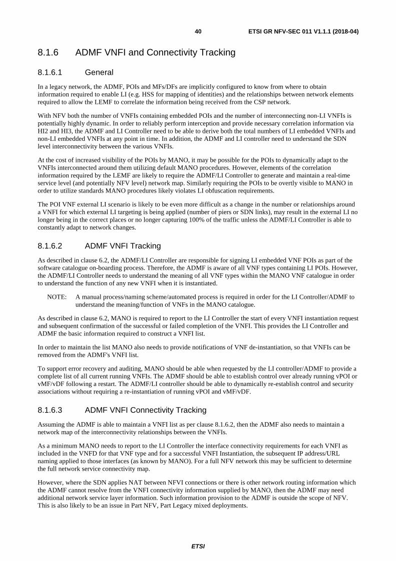
ETSI
ETSI GR NFV-SEC 011 V1.1.1 (2018-04)40
8.1.6 ADMF VNFI and Connectivity Tracking
8.1.6.1 General
In a legacy network, the ADMF, POIs and MFs/DFs are implicitly configured to know from where to obtain information required to enable LI (e.g. HSS for mapping of identities) and the relationships between network elements required to allow the LEMF to correlate the information being received from the CSP network.
With NFV both the number of VNFIs containing embedded POIs and the number of interconnecting non-LI VNFIs is potentially highly dynamic. In order to reliably perform interception and provide necessary correlation information via HI2 and HI3, the ADMF and LI Controller need to be able to derive both the total numbers of LI embedded VNFIs and non-LI embedded VNFIs at any point in time. In addition, the ADMF and LI controller need to understand the SDN level interconnectivity between the various VNFIs.
At the cost of increased visibility of the POIs by MANO, it may be possible for the POIs to dynamically adapt to the VNFIs interconnected around them utilizing default MANO procedures. However, elements of the correlation information required by the LEMF are likely to require the ADMF/LI Controller to generate and maintain a real-time service level (and potentially NFV level) network map. Similarly requiring the POIs to be overtly visible to MANO in order to utilize standards MANO procedures likely violates LI obfuscation requirements.
The POI VNF external LI scenario is likely to be even more difficult as a change in the number or relationships around a VNFI for which external LI targeting is being applied (number of piers or SDN links), may result in the external LI no longer being in the correct places or no longer capturing 100% of the traffic unless the ADMF/LI Controller is able to constantly adapt to network changes.
8.1.6.2 ADMF VNFI Tracking
As described in clause 6.2, the ADMF/LI Controller are responsible for signing LI embedded VNF POIs as part of the software catalogue on-boarding process. Therefore, the ADMF is aware of all VNF types containing LI POIs. However, the ADMF/LI Controller needs to understand the meaning of all VNF types within the MANO VNF catalogue in order to understand the function of any new VNFI when it is instantiated.
NOTE: A manual process/naming scheme/automated process is required in order for the LI Controller/ADMF to understand the meaning/function of VNFs in the MANO catalogue.
As described in clause 6.2, MANO is required to report to the LI Controller the start of every VNFI instantiation request and subsequent confirmation of the successful or failed completion of the VNFI. This provides the LI Controller and ADMF the basic information required to construct a VNFI list.
In order to maintain the list MANO also needs to provide notifications of VNF de-instantiation, so that VNFIs can be removed from the ADMF's VNFI list.
To support error recovery and auditing, MANO should be able when requested by the LI controller/ADMF to provide a complete list of all current running VNFIs. The ADMF should be able to establish control over already running vPOI or vMF/vDF following a restart. The ADMF/LI controller should be able to dynamically re-establish control and security associations without requiring a re-instantiation of running vPOI and vMF/vDF.
8.1.6.3 ADMF VNFI Connectivity Tracking
Assuming the ADMF is able to maintain a VNFI list as per clause 8.1.6.2, then the ADMF also needs to maintain a network map of the interconnectivity relationships between the VNFIs.
As a minimum MANO needs to report to the LI Controller the interface connectivity requirements for each VNFI as included in the VNFD for that VNF type and for a successful VNFI Instantiation, the subsequent IP address/URL naming applied to those interfaces (as known by MANO). For a full NFV network this may be sufficient to determine the full network service connectivity map.
However, where the SDN applies NAT between NFVI connections or there is other network routing information which the ADMF cannot resolve from the VNFI connectivity information supplied by MANO, then the ADMF may need additional network service layer information. Such information provision to the ADMF is outside the scope of NFV. This is also likely to be an issue in Part NFV, Part Legacy mixed deployments.

ETSI
ETSI GR NFV-SEC 011 V1.1.1 (2018-04)41
As with clause 8.1.6.2, the ADMF/LI controller should be able to obtain sufficient information to re-establish the current VNFI connectivity map following an ADMF/LI controller restart or where LI is enabled in the network after the first VNFIs are instantiated.
8.1.6.4 VNFI scaling/migration
If a VNFI is scaled this will have a number of potential impacts on the ADMF's VNFI connectivity map:
1) If a VNFCI is added to an existing VNFI, the number of or bandwidth of the SDN links may change. The ADMF should be able to receive sufficient information from MANO to understand such changes, as part of the scaling process.
2) If a VNFI is migrated from one location to another, the ADMF needs to receive sufficient information from MANO to be able to understand such changes and update the VNFI list and VNFI connectivity map accordingly.
NOTE: Extensions to existing MANO procedures may be required to provide sufficient information to the LI Controller/ADMF as a result of VNFI migrations or scaling.
8.2 LI Solutions Evolution Stages
8.2.1 Overview
The large number of possible paths in evolving native legacy networks towards truly virtualised networks makes the formulation of a separate LI solutions for each path, and the myriads of hybrid network combinations that result, highly impractical. The chosen approach therefore considers the most probable evolution paths, identifies appropriate intermediate steps, and considers a LI solution for each path as well as the associated network challenges and solutions.
The speed of transformation and possible evolution path variants depend on the various operator/CSP strategies, while accepting the likelihood that legacy network nodes will operate for long time, at least finally as backup systems. The lawful interception function, administration and data mediation should therefore be supported on such legacy nodes as well throughout the network evolution.
The operator/CSP needs to first consider how the LI solution impacts the overall network virtualisation strategy. A telco network is composed of multiple sites and the operator could choose to replace an entire site with a fully virtualised network, or virtualise only part of it. Moreover, the operator will likely consolidate the diverse network sites into fewer datacentres. This implies a re-design of inter-site networking, including the LI network.
Another important consideration in the operator's network evolution strategy is the concern about potential network performance degradation. At the same time, the operator will seek VNFs that will operate at higher speeds in the upper layers of the communication stack, such as in application services or signalling nodes.
Consequently, virtualised signalling nodes should interwork with physical media nodes supporting media session handling. The LI impact from such a scenario, apart from maintaining the security of the interworking interfaces, increases the complexity in keeping the correlation of service information, signalling and media content for the same intercepted session that is served by both physical and virtual nodes. For example, in an IMS network one or more physical Border Gateways can be dynamically associated and/or dissociated with one or more virtual Serving Border Gateways. The MF should therefore be aware of the actual combination of a virtual SBG instance with the physical BGF serving a SIP session and the associated media. In practice, the VNFI connectivity tracking ability of the LI ADMF Controller described in clause 6.5.1 should be extended with information about VNFI and PNF connections.
Given the considerations above while aiming to provide a simplified view of how to incorporate LI into an evolving virtualised network, four main LI implementation evolutionary stages have been identified. The stages described herein are not intended as mandatory evolution paths, but as generic guidelines. The operator/CSP may skip some of the recommended stages or implement only initial stages (e.g. because the LI virtualisation benefits are not seen as balanced against the increased LI security risk). LI for evolved networks will also depend on the actual availability of the security control infrastructure described in ETSI GS NFV-SEC 012 [i.7] and ETSI GS NFV-SEC 013 [i.8], as well as the additional management of LI vPOI's via the LI Controller (as described in clause 6).
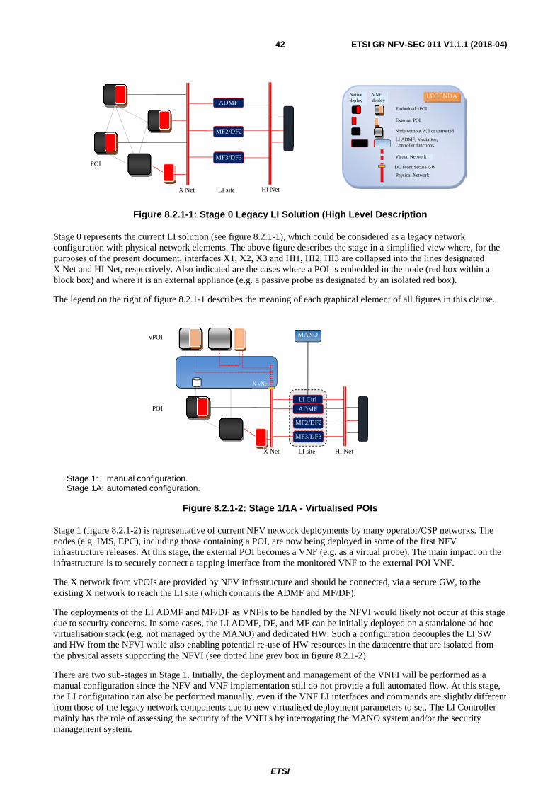
ETSI
ETSI GR NFV-SEC 011 V1.1.1 (2018-04)42
Figure 8.2.1-1: Stage 0 Legacy LI Solution (High Level Description
Stage 0 represents the current LI solution (see figure 8.2.1-1), which could be considered as a legacy network configuration with physical network elements. The above figure describes the stage in a simplified view where, for the purposes of the present document, interfaces X1, X2, X3 and HI1, HI2, HI3 are collapsed into the lines designated X Net and HI Net, respectively. Also indicated are the cases where a POI is embedded in the node (red box within a block box) and where it is an external appliance (e.g. a passive probe as designated by an isolated red box).
The legend on the right of figure 8.2.1-1 describes the meaning of each graphical element of all figures in this clause.
Stage 1: manual configuration. Stage 1A: automated configuration.
Figure 8.2.1-2: Stage 1/1A - Virtualised POIs
Stage 1 (figure 8.2.1-2) is representative of current NFV network deployments by many operator/CSP networks. The nodes (e.g. IMS, EPC), including those containing a POI, are now being deployed in some of the first NFV infrastructure releases. At this stage, the external POI becomes a VNF (e.g. as a virtual probe). The main impact on the infrastructure is to securely connect a tapping interface from the monitored VNF to the external POI VNF.
The X network from vPOIs are provided by NFV infrastructure and should be connected, via a secure GW, to the existing X network to reach the LI site (which contains the ADMF and MF/DF).
The deployments of the LI ADMF and MF/DF as VNFIs to be handled by the NFVI would likely not occur at this stage due to security concerns. In some cases, the LI ADMF, DF, and MF can be initially deployed on a standalone ad hoc virtualisation stack (e.g. not managed by the MANO) and dedicated HW. Such a configuration decouples the LI SW and HW from the NFVI while also enabling potential re-use of HW resources in the datacentre that are isolated from the physical assets supporting the NFVI (see dotted line grey box in figure 8.2.1-2).
There are two sub-stages in Stage 1. Initially, the deployment and management of the VNFI will be performed as a manual configuration since the NFV and VNF implementation still do not provide a full automated flow. At this stage, the LI configuration can also be performed manually, even if the VNF LI interfaces and commands are slightly different from those of the legacy network components due to new virtualised deployment parameters to set. The LI Controller mainly has the role of assessing the security of the VNFI's by interrogating the MANO system and/or the security management system.
X Net
POI
LI site HI Net
ADMF
MF2/DF2
MF3/DF3
Embedded vPOI External POI Node without POI or untrusted PoI LI ADMF, Mediation, Controller functions
Native deploy VNF
deploy
LEGENDA
Virtual Network Physical Network
DC Front Secure GW
NFVI
vPOI
POI
MANO
X vNet
ADMF
LI site
MF2/DF2 MF3/DF3
LI Ctrl
HI Net X Net
LEMF

ETSI
ETSI GR NFV-SEC 011 V1.1.1 (2018-04)43
In Stage 1A, fully automated VNF lifecycle management is assumed to be in place; therefore, the LI Controller logic needs to evolve and participate actively for LI configuration (as described in clause 6.2) and coordinate changes in the VNF with changes in associated PNF.
Figure 8.2.1-3: Stage 2 - Virtual MFs/DFs (Restricted pooled host or unrestricted pooled host for MF only)
Stage 2 (figure 8.2.1-3): As the NFV security support matures, the LI mediation and delivery functions would be deployed as VNFI's to leverage cloud resources scalability. The native MF/DF functions can still be present in the LI site as a backup solution.
The ADMF is expected to still reside for long time on a separate physical system or in an isolated datacentre either as virtualised or native application. In addition, isolating the ADMF enables it to serve as an external LI Root of Trust. This helps to establish requisite security controls of the virtualised LI functions, meeting the security level required by the NFV infrastructure.
Figure 8.2.1-4: Stage 3 - Virtual ADMF/LI Ctrl (Stage 3: on pooled restricted host � Stage 3A on pooled unrestricted host)
A fully virtualised LI solution, as represented by figure 8.2.1-4 (Stage 3), possesses the three main LI functions: LI ADMF, MF and DF, all deployed as separate virtualised VNFCI or VNFI. The MF's virtual instances could be distributed in the virtual network (in an unrestricted resource pool) close to the monitored VNFs and scaled according to their lifecycle and traffic load. The delivery function would act as a gateway VNF to external LEMFs. Its scaling is constrained by LEMF capabilities. The virtual LI ADMF coordinates MF, DF and POI as before, but with interconnection interface protocols more suitable to the highly dynamic virtualised environment. The LI Controller will further extend its capability to participate in the secure management instantiation of the virtualised LI functions.
All of the legacy VNF's would need to be connected to the virtualised LI site i.e. the X network should cover both physical and virtualised network segments, keeping separation between the two network domains.
NFVI
vPOI
ADMF
X Net
POI
LI site
MF2/DF2 MF3/DF3
LI Ctrl
MANO
X vNet
HI Net
vMF
HI vNet
vDF
LEMF
NFVI
vPOI
X Net
POI
LI virtual
site
MANO
X vNet
HI Net
vMF
HI vNet
vDF ADMF LI Ctrl
LEMF

ETSI
ETSI GR NFV-SEC 011 V1.1.1 (2018-04)44
The LI Controller can be integrated into the LI-ADMF, or optionally deployed as a separate VNFI. The LI Controller's deployment as a standalone application on separate LI-dedicated HW also allows it to keep its role as an external LI Root of Trust, with proper security handling of native and virtualised POI's all with separate credentials.
Figure 8.2.1-5: Stage 4 - Legacy node connected to a SDN network
Stage 4 (figure 8.2.1-5) considers a further evolution variant, where the whole network becomes a SDN-based network, including connections to physical nodes. The X network will then be fully programmable, but it will also need to be secured by the SDN controller with a possible interaction with the LI Controller/LI ADMF.
Handover Interface HI connections would remain provided by a traditional network since they are exposed external to the LEMFs.
Clauses 8.2.2, 8.2.3, 8.2.4 and 8.2.5 summarize the main changes at each stage in the transition of a network from that of a legacy architecture to a full NFV architecture. Important security controls, modifications to interfaces, and changes to management systems are recommended to mitigate security risks and enable a smooth migration from physical nodes to VNF deployment with secure lifecycle management.
8.2.2 Stage 1 Evolution
This clause considers POI Virtualisation as first evolution from Legacy Network (i.e. the stage 0) and shown in figure 8.2.1-2 with two sub-steps: the stage 1 with limited automated deployment and stage 1A where the VNF lifecycle is fully automated.
The first task for the new entity LI controller is to handle the co-existence in the CSP network of both virtual POI in VNFs and POI in legacy physical nodes. This implies impacts on VNF side as well as on virtual and physical network configuration.
More in detail the following controls are envisioned:
NOTE: This list does not pretend to be exhaustive.
• "Virtualised POI Identificator": Virtual POI should enhance X interface with a VNF identificator from which the ADMF/MF can deduct it is virtualised and related virtual instance identifier parameters.
• "Extended Correlation Id": A further recommended improvement on X interface is to add an extended LI session correlation id on with additional info on actual virtual node identifiers.
• "Additional VNFD fields for LI": to allow the POI automated deployment in VNF lifecycle in stage 1A, the VNFD should be modified with additional parameters. A minimal set of parameters to enable POI initial connection to LI ADMF/controller e.g. adding LI ADMF IP, preferred X security protocol.
• "LI handling with virtual and physical POIs": The ADMF/LI Controller should implement different security handling of virtual and physical legacy POI as well as provide additional configuration parameters to enable correlation of interception info in MF/DF on data received from both. It means, as example, to distribute differentiated X2, X3 encryption keys and/or certificates to virtual and physical POI and receiving MF/DF.
NFVI
vPOI
X Net
POI
LI virtual
site
MANO
X vNet
HI Net
vMF
HI vNet
vDF ADMF LI Ctrl
LEMF
NFVI
MANO

ETSI
ETSI GR NFV-SEC 011 V1.1.1 (2018-04)45
• "Secure gateway between virtual and physical network": A security gateway keeping separation of the physical and virtual networks is needed to avoid cross attack to internal LI interfaces from the weakest network domain.
• "MF/DF pre-dimensioning": An adequate pre-dimensioning of MF/DF functions is needed at this stage and a range of possible source X2, X3 IPs should be pre-configured in LI Controller and ADMF as MF/DF is not virtualised yet. In stage 1A the LI controller/ADMF can instead get notified about scaling events and newly assigned X2, X3 IP addresses from MANO (via LI Os-1) or from VNF instance (via X0).
• "MF/DF resilience to virtual POI dynamicity": The MF/DF should be resilient to virtual POI dynamic changes, e.g. VNF scaling-in termination or migration should not lead to meaningless LI alarms or to useless repetitive X connection recovery tentatives.
• "Adaptations to cloud based HA and DR": In NFV the five 9's availability is achieved differently than in legacy and typically with a coordinated multiple termination, migration or re-instantiation of VNFI. In stage 1 the ADMF, MF and DF should be resilient to the HA/DR procedure i.e. not wrongly inferring from some VNFI terminations that the associated service is stopped. In stage1A the LI ADFM/Controller can be notified about HA/DR events and recovered service details via LI-Os1 (or NBI) interface and reconfigure MF/DF accordingly.
• "Low trust embedded POI to TCF configuration": Also low trust embedded POI requires the LI Controller/ADMF configures (via X0) the connections with the controlling TCF function. This is expecting to be done mostly manually in stage 1 and automatized in stage 1A.
• "Not embedded POI configuration": The "Not embedded" POIs instantiation and related VNF tapping points configuration, in stage 1, are expected to be manually instantiated. LI ADMF/Controller should then configure the instantiated POI via X0. In stage 1A Automation can be realized in several ways e.g. by pre-configuring a POI VNF in the NSD of the service to monitor or, more secure but more complex to handle, extending LI Os1 I/F in order to drive POI VNF instantiation by LI ADMF/Controller.
• "Enforce security during legacy to virtualised POI migration": LI data can be exposed when a network node migrate to a virtual VNF. In stage 1 the LI ADMF/Controller could protect POI configuration data from exposure in general backup area acting as temporary/secure backup. Note that a dedicate X0 or X1 command would be required.
• "Enforce security during virtual POI upgrade": Stage 1 is seen similar to previous scenario. In stage 1A the POI configuration can be deleted before the upgrade since LI ADMF/Controller can restore it on a re-instantiated POI new version using the latest configuration data stored during previous version POI instantiation. No service interruption is expected as both old and new version VNF instances can be kept running during the upgrade.
8.2.3 Stage 2 Evolution
This clause considers next step in evolution beyond stage 1 in clause 8.2.2 where MF and DF are also virtualised as shown in figure 8.2.1-3.
The virtualisation of mediation and delivery functions enables an higher elasticity of LI solution in terms of optimal allocation of MF and DF over the network i.e. instantiation of MF close to the POI's to reduce latency and bandwidth and handling differentiated scalability of MF and DF as the first depends on POI's scaling behaviour while the other on LEMFs number and receiving capability.
As pre-requisite, the security functions in the MANO (or security controller) to allocate a restricted pool of resource for virtual MF and/or virtual DF should be available (according to ETSI GS NFV-SEC 012 [i.7] and ETSI GS NFV-SEC 013 [i.8]) however since the MF could also be instantiated in the network close to POI's a MF drawn from an unrestricted pool of resources could be reasonable in some cases.
The legacy MF and DF are expected to temporarily co-exist with virtualised MF and DF however a smooth migration between the two should be supported.

ETSI
ETSI GR NFV-SEC 011 V1.1.1 (2018-04)46
Main foreseen impacts in addition to previous stage are:
• "Dynamic instantiation of MF2, MF3 and DF2, DF3": the MF and DF should be packaged in way they could be onboarded in the catalog and instantiates by MANO either:
- manually (likely in a first release);
- pre-configured in the NSD together with virtual POI and other VNFs;
- on LI controller/ADMF request via an existing or new MANO interface.
• "Handling of Initial credential/keys in VNFD": The VNFD specification and MANO should support the possibility to securely handle LI initial parameters and key/credentials for vMF/vDF function, i.e. to support a protection mechanism of sensitive data in VNFD and NSD made them accessible to LI authorized roles only.
• "X2, X3 connection dynamic configuration": It should be configured the X2, X3 network connections between vPOI and MFs, and HI's between DFs and/or the LRPG. This can be achieved via pre-configuration in MF, DF VNFD and NSD or dynamically triggered by a LI controller request to MANO.
• "MF and DF configuration via LI Controller": the LI Controller/ADMF should configure all the MF/DF application parameters via a specific MD/DF configuration interface (named X0_2).
• "MF/DF instantiation policy driven": the number and the location of instantiated vMF and vDF. close to POI should be decided by a configured policy. The policy should be transmitted from ADMF or LI controller to the NFV via LI-Os1 depending of the network service type setup. The POI types definition, network scenarios (e.g. VoLTE, IMS, Packet Core, 5G's network slices) nomenclature and LI policy format are for further specification and depends on terminology, identity management and policy formats under definition in other IFA, SOL, EVE, SEC work items.
• "Handling of physical and virtual MF/DF co-existence": ADMF should be informed if a MF/DF is virtual or physical. Similarly, to POI it would require a new flag on X1_2, X1_3 and/or X0_2, X0_3 interfaces. The LI controller should then setup different connection credentials on physical and virtual MF/DF to avoid cross-attack leveraging on the one with the weakest security.
8.2.4 Stage 3 Evolution
This clause considers next step in evolution beyond stage 2 in clause 8.2.3 where ADMF/LI controller are deployed as virtual applications as shown in figure 8.2.1-4.
The ADMF deployed as VNF requires that an isolated area of the cloud infrastructure is assigned to it. The allocated resource set should be physically separated or, in 3A when platform provides all the requirements for sensitive function support, as described in ETSI GS NFV-SEC 012 [i.7], logically separated. Moreover the instantiation of ADMF in full virtualised environment brings several other changes in the overall LI solution:
• "Physical POI connected to ADMF through virtual network": The virtualised ADMF is connected via virtual network therefore physical POI network needs to be re-routed/tunnelized trough virtual network (security gateway between the two network should be configured in order to allow also X1 traffic).
• "Physical and/or logical separation of ADMF sensitive data": The ADMF data is the most sensitive data in a LI solution, a separate HW disk storage needs to be setup and, in 3A stage, logical storage should be protected by advanced security methods like data slices encryption and keyless signature.
• "Possibility to use a LI root of trust provided by the infrastructure": External LI HW root of trust could be not needed anymore as the platform provide sufficient trust for LI anyway it still remains a good practice and can be very useful during VNF or data migration between different cloud platforms or as backup in case of security incidents.
• "LI controller separately installed": The LI Controller can be the first component to be separately installed in a LI solution and manually configured by LI personnel. It is tasked to manage the automatic secure instantiation and configuration of the other LI functions and to be the unique and trusted entry point to audit, at any time, the virtual LI solution in place.

ETSI
ETSI GR NFV-SEC 011 V1.1.1 (2018-04)47
8.2.5 Stage 4 Evolution
This clause considers next step in evolution beyond stage 3 in clause 8.2.3 where ADMF/LI controller are deployed as virtual applications and a SDN based network is used to connect also legacy physical IAP nodes as shown in figure 8.2.1-5.
The introduction of a network fully programmable also for legacy POI connection enables the maximum flexibility and simplifies the handling of overall LI security. As pre-requisite, the infrastructure should implement all requirements for sensitive function support, according to ETSI GS NFV-SEC 012 [i.7]. Moreover, it should have in place controls and support SFC (Service Function Chain) security policy checks as indicated in ETSI GS NFV-SEC 013 [i.8].
Foreseen additional impacts to implement respect to previous stage could be:
• "NSD and/or LI policy modification": NSD specifications and/or need to be modifies in order to manage virtual links between LI controller/ADMF, MF and both virtual and physical POIs.
• "SDN based security controls": The security gateway between virtual and physical network may get replaced by an equivalent separation security controls leveraging SDN programmability e.g. automatic re-routing of suspect traffic or enforcing security screeners in traffic chain.
• "Physical POI network dynamic configuration": The overall POI Lifecycle management flows should include also the dynamic configuration of physical POI in way similar to what is done for virtual POI but limited to network configuration aspects. E.g. considering figure 8.1.3-1, it means to perform only the steps 10 to 14 where a practical case is to notify to the LI controller/ADMF about the X1 IPs assigned to a physical POI by MANO and the initial credentials to use and let LI controller configure the LI function in the POI.

ETSI
ETSI GR NFV-SEC 011 V1.1.1 (2018-04)48
Annex A (informative): Authors & contributors The following people have contributed to the present document:
Rapporteur: Mr Alex Leadbeater, BT Group Plc (UK)
Other contributors: Mr Michael Bilca, OTD (USA)
Domenico Cione, Ericsson (Italy)
Giuseppe Amato, Ericsson (Italy)
Ben Epstein, Aqsacom S.A.S (USA)

ETSI
ETSI GR NFV-SEC 011 V1.1.1 (2018-04)49
History
Document history
V1.1.1 April 2018 Publication


![ETSI GS NFV-INF 004 V1.1 · [1] ETSI GS NFV-INF 001 (V1.1.1): "Network Functions Virtualisation (NFV); Infrastructure Overview". 2.2 Informative references References are either specific](https://img.dokumen.tips/doc/110x75/5f797d6d7032da5bd63a2da3/etsi-gs-nfv-inf-004-v11-1-etsi-gs-nfv-inf-001-v111-network-functions.jpg)