Embed Size (px)
Citation preview

Note: This test report is prepared for the customer shown above and for the equipment described herein. It may not be duplicated or used in part without prior written consent from Bay Area Compliance Laboratories Corp. This report is valid only with a valid digital signature. The digital signature may be available only under the Adobe software above version 7.0.
ETSI EN 301 489-1 V2.2.0 (2017-03) ETSI EN 301 489-3 V2.1.1 (2017-03)
ETSI EN 301 489-17 V3.2.0 (2017-03)
TEST REPORT For
Shanghai Bwave Technology Co.,Ltd.
6F, Building 12, 399 Keyuan Road,Zhangjiang Hi-Tech Park, Shanghai, China
Model: BW8800
Report Type:
Amended Report
Product Type:
wireless module
Test Engineer: Phil Zhu
Report Number: RKS170417008-00A
Report Date: 2017-04-20
Reviewed By: Kamp Chen EMC Leader
Test Laboratory:
Bay Area Compliance Laboratories Corp. (Kunshan) No.248 Chenghu Road,Kunshan,Jiangsu province,China Tel: +86-0512-86175000 Fax: +86-0512-88934268 www.baclcorp.com.cn

Bay Area Compliance Laboratories Corp. (Kunshan) Report No.: RKS170417008-00A
ETSI EN 301 489-1 V2.2.0 (2017-03), ETSI EN 301 489-3 V2.1.1 (2017-03) Page 2 of 7 ETSI EN 301 489-17 V3.2.0 (2017-03)
TABLE OF CONTENTS
DOCUMENT REVISION HISTORY ......................................................................................................................... 3
7.2 -RF ELECTROMAGNETIC FIELD (80 MHz - 6000 MHz) .................................................................................... 4 MEASUREMENT UNCERTAINTY .................................................................................................................................... 4 TEST EQUIPMENT ......................................................................................................................................................... 4 TEST SYSTEM SETUP .................................................................................................................................................... 4 TEST STANDARD .......................................................................................................................................................... 5 TEST PROCEDURE ........................................................................................................................................................ 5 TEST DATA AND SETUP PHOTO .................................................................................................................................... 5
BELOW IS THE ORIGINAL REPORT ..................................................................................................................... 7

Bay Area Compliance Laboratories Corp. (Kunshan) Report No.: RKS170417008-00A
ETSI EN 301 489-1 V2.2.0 (2017-03), ETSI EN 301 489-3 V2.1.1 (2017-03) Page 3 of 7 ETSI EN 301 489-17 V3.2.0 (2017-03)
DOCUMENT REVISION HISTORY
Revision Number Report Number Description of Revision Date of Issue
1 RKS160310001-00O Original Report 2016-03-17
2 RKS170417008-00A Amended Report 2017-04-20
Note: This is an amended report application based on RKS160310001-00O, the details as below: 1. Update ETSI EN 301 489-1 V1.9.2 (2011-09) to ETSI EN 301 489-1 V2.2.0 (2017-03). 2. Update ETSI EN 301 489-3 V1.6.1 (2013-08) to ETSI EN 301 489-3 V2.1.1 (2017-03). 3. Update ETSI EN 301 489-17 V2.2.1 (2012-09) to ETSI EN 301 489-17 V3.2.0 (2017-03). For above difference, besides RF Electromagnetic Field ,all the test data and EUT photos were copied from the original report RKS160310001-00O that issued on 2016-03-17.
Bay Area Compliance Laboratories Corp. (Kunshan) Report No.: RKS170417008-00A
ETSI EN 301 489-1 V2.2.0 (2017-03), ETSI EN 301 489-3 V2.1.1 (2017-03) Page 4 of 7 ETSI EN 301 489-17 V3.2.0 (2017-03)
7.2 -RF ELECTROMAGNETIC FIELD (80 MHz - 6000 MHz) Measurement Uncertainty Ulab (measurement uncertainty of lab) and UEN (measurement uncertainty of EN 61000-4-3) please refer to the following:
Parameter UEN Ulab
Calibration process 1.88 dB 1.88 dB
Level setting 2.19 dB 2.19 dB
Test Equipment
Manufacturer Description Model Serial
Number Calibration
Date Calibration Due Date
HP Signal Generator E4421B US38440505 2015-11-25 2017-11-24Agilent Signal Generator 8665B 3744A01692 2017-01-12 2018-01-12
Amplifier Research Power Amplifier 200W1000M3A 18062 NCR NCR
A&R Power Amplifier 500W100B 0348446 NCR NCR
A&R Power Amplifier 60S1G6 0348712 NCR NCR
Sunol Sciences Bi-log Antenna JB3 A040904-1 2016-01-09 2019-01-08
Amplifier Research Power Amplifier 10S1GRM1 18060 NCR NCR
ETS Horn Antenna 3115 6229 2016-01-11 2019-01-10 * Statement of Traceability: Bay Area Compliance Laboratories Corp. (Kunshan) attests that all calibrations have been performed in accordance to requirements that traceable to National Primary Standards and International System of Units (SI).
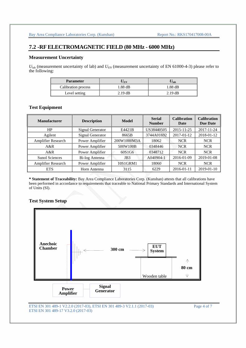
Test System Setup Wooden table
300 cmEUT
System
80 cm
Anechoic Chamber
Power Amplifier
Signal Generator

Bay Area Compliance Laboratories Corp. (Kunshan) Report No.: RKS170417008-00A
ETSI EN 301 489-1 V2.2.0 (2017-03), ETSI EN 301 489-3 V2.1.1 (2017-03) Page 5 of 7 ETSI EN 301 489-17 V3.2.0 (2017-03)
Test Standard
ETSI EN 301 489-1 V2.2.0 (2017-03) / EN 61000-4-3:2006+A1:2008+A2:2010 Test Level 2 at 3V / m Test Levels and Performance Criterion
Test Level
Level Field Strength V/m 1. 12. 3 3. 10 X. Special
Performance Criterion: A
Test Procedure
The EUT and its simulators are placed on a turn table which is 0.8 meter above the ground. The EUT is set 3 meters away from the Receiving antenna which is mounted on an antenna tower. Both horizontal and vertical polarizations of the antenna are set on test. Each of the four sides of EUT must be faced this Receiving antenna and measured individually. In order to judge the EUT performance, a CCD camera are used to monitor the EUT.
All the scanning conditions are as follows:
Condition of Test Remarks ---------------------------------------------- ----------------------------------
1. Field Strength 3 V/m (Test Level 2) 2. Radiated Signal 1 kHz, 80% AM, sine wave 3. Scanning Frequency 80 MHz– 6000 MHz 4. Scanning Frequency Step 1% 5. Dwell Time 3 Sec.
Test Data and Setup Photo
Environmental Conditions
Temperature: 24.3 °C Relative Humidity: 53 %
ATM Pressure: 100.2kPa
The testing was performed by Phil Zhu on 2017-04-18.
Test Mode: Operating

Bay Area Compliance Laboratories Corp. (Kunshan) Report No.: RKS170417008-00A
ETSI EN 301 489-1 V2.2.0 (2017-03), ETSI EN 301 489-3 V2.1.1 (2017-03) Page 6 of 7 ETSI EN 301 489-17 V3.2.0 (2017-03)
Frequency Range (MHz)
Front Side (3 V/m) Rear Side (3 V/m) Left Side (3 V/m) Right Side (3 V/m)
VERT HORI VERT HORI VERT HORI VERT HORI
80-6000 A A A A A A A A
Note: “A” stand for, during test, operate as intended no loss of function, no degradation of performance, no unintentional transmissions and after test, no degradation of performance, no loss of function, no loss of stored data or user programmable functions.
Test Setup photo
Bay Area Compliance Laboratories Corp. (Kunshan) Report No.: RKS170417008-00A
ETSI EN 301 489-1 V2.2.0 (2017-03), ETSI EN 301 489-3 V2.1.1 (2017-03) Page 7 of 7 ETSI EN 301 489-17 V3.2.0 (2017-03)
BELOW IS THE ORIGINAL REPORT

FINAL
Note: This test report is prepared for the customer shown above and for the equipment described herein. It may not be duplicated or used in part without prior written consent from Bay Area Compliance Laboratories Corp. This report is valid only with a valid digital signature. The digital signature may be available only under the Adobe software above version 7.0.
ETSI EN 301 489-1 V1.9.2 (2011-09) ETSI EN 301 489-3 V1.6.1 (2013-08)
ETSI EN 301 489-17 V2.2.1 (2012-09)
TEST REPORT For
Shanghai Bwave Technology Co.,Ltd. 6F, Building 12, 399 Keyuan Road,Zhangjiang Hi-Tech Park, Shanghai, China
Model: BW8800
Report Type:
Original Report
Product Type:
wireless module
Test Engineer: Allen.tian
Report Number: RKS160310001-00O
Report Date: 2016-03-17
Reviewed By: Jesse.huang EMC Manager
Test Laboratory:
Bay Area Compliance Laboratories Corp. (Kunshan) Chenghu Road,Kunshan Development Zone No.248,Kunshan, Jiangsu, China Tel: +86-0512-86175000 Fax: +86-0512-88934268 www.baclcorp.com.cn

FINAL
Bay Area Compliance Laboratories Corp. (Kunshan) Report No.: RKS160310001-00O
Page 2 of 50
TABLE OF CONTENTS
GENERAL INFORMATION ....................................................................................................................................... 4
PRODUCT DESCRIPTION FOR EQUIPMENT UNDER TEST (EUT) ..................................................................................... 4 OBJECTIVE ................................................................................................................................................................... 4 TEST METHODOLOGY .................................................................................................................................................. 4 TEST FACILITY ............................................................................................................................................................. 4
SYSTEM TEST CONFIGURATION .......................................................................................................................... 5
DESCRIPTION OF TEST CONFIGURATION ...................................................................................................................... 5 EUT EXERCISE SOFTWARE .......................................................................................................................................... 5 EQUIPMENT MODIFICATIONS ....................................................................................................................................... 5 SUPPORT EQUIPMENT LIST AND DETAILS .................................................................................................................... 5 EXTERNAL I/O CABLE .................................................................................................................................................. 5 CONFIGURATION OF TEST SETUP ................................................................................................................................. 6
SUMMARY OF TEST RESULTS ............................................................................................................................... 7
7.1 - CONDUCTED EMISSIONS ................................................................................................................................ 8
MEASUREMENT UNCERTAINTY .................................................................................................................................... 8 EUT SETUP .................................................................................................................................................................. 8 EMI TEST RECEIVER SETUP ......................................................................................................................................... 9 TEST EQUIPMENT LIST AND DETAILS ........................................................................................................................... 9 TEST PROCEDURE ........................................................................................................................................................ 9 CORRECTED AMPLITUDE & MARGIN CALCULATION ................................................................................................. 10 TEST RESULTS SUMMARY .......................................................................................................................................... 10 TEST DATA ................................................................................................................................................................ 10
7.1 - RADIATED EMISSIONS .................................................................................................................................. 13
MEASUREMENT UNCERTAINTY .................................................................................................................................. 13 TEST SYSTEM SETUP .................................................................................................................................................. 13 EMI TEST RECEIVER SETUP ....................................................................................................................................... 14 TEST EQUIPMENT LIST AND DETAILS ......................................................................................................................... 15 TEST PROCEDURE ...................................................................................................................................................... 15 CORRECTED AMPLITUDE & MARGIN CALCULATION ................................................................................................. 15 TEST RESULTS SUMMARY .......................................................................................................................................... 15 TEST DATA ................................................................................................................................................................ 16
7.2 -RF ELECTROMAGNETIC FIELD (80 - 1000MHz, 1400 - 2700 MHz) ............................................................... 18
MEASUREMENT UNCERTAINTY .................................................................................................................................. 18 TEST EQUIPMENT ....................................................................................................................................................... 18 TEST SYSTEM SETUP .................................................................................................................................................. 18 TEST STANDARD ........................................................................................................................................................ 19 TEST PROCEDURE ...................................................................................................................................................... 19 TEST DATA AND SETUP PHOTO .................................................................................................................................. 19
7.2 - ELECTROSTATIC DISCHARGE ................................................................................................................... 21
MEASUREMENT UNCERTAINTY .................................................................................................................................. 21 TEST EQUIPMENT ....................................................................................................................................................... 21 TEST SYSTEM SETUP .................................................................................................................................................. 21 TEST STANDARD ........................................................................................................................................................ 21 TEST PROCEDURE ...................................................................................................................................................... 22 TEST DATA AND SETUP PHOTO .................................................................................................................................. 22
7.2 - ELECTRICAL FAST TRANSIENT IMMUNITY .......................................................................................... 26

FINAL
Bay Area Compliance Laboratories Corp. (Kunshan) Report No.: RKS160310001-00O
Page 3 of 50
MEASUREMENT UNCERTAINTY .................................................................................................................................. 26 TEST EQUIPMENT ....................................................................................................................................................... 26 TEST SYSTEM SETUP .................................................................................................................................................. 26 TEST STANDARD ........................................................................................................................................................ 26 TEST PROCEDURE ...................................................................................................................................................... 27 TEST DATA AND SETUP PHOTO .................................................................................................................................. 27
7.2 - RF COMMON MODE ........................................................................................................................................ 29
MEASUREMENT UNCERTAINTY .................................................................................................................................. 29 TEST EQUIPMENT ....................................................................................................................................................... 29 TEST SETUP ................................................................................................................................................................ 29 TEST STANDARD ........................................................................................................................................................ 29 TEST PROCEDURE ...................................................................................................................................................... 30 TEST DATA AND SETUP PHOTO .................................................................................................................................. 30
7.2 - SURGES, LINE TO LINE AND LINE TO GROUND .................................................................................... 32
TEST EQUIPMENT ....................................................................................................................................................... 32 TEST SYSTEM SETUP .................................................................................................................................................. 32 TEST STANDARD ........................................................................................................................................................ 32 TEST PROCEDURE ...................................................................................................................................................... 33 TEST DATA AND SETUP PHOTO .................................................................................................................................. 33
7.2 - VOLTAGE DIPS AND INTERRUPTIONS IMMUNITY TEST ................................................................... 35
TEST EQUIPMENT ....................................................................................................................................................... 35 TEST SETUP ................................................................................................................................................................ 35 TEST STANDARD ........................................................................................................................................................ 35 TEST PROCEDURE ...................................................................................................................................................... 36 TEST DATA AND SETUP PHOTO .................................................................................................................................. 36
7.1 - HARMONIC CURRENT EMISSIONS ............................................................................................................ 38
7.1 - VOLTAGE FLUCTUATION AND FLICKER ................................................................................................ 39
TEST EQUIPMENT ....................................................................................................................................................... 39 TEST SYSTEM SETUP .................................................................................................................................................. 39 TEST STANDARD ........................................................................................................................................................ 39 TEST DATA AND SETUP PHOTO .................................................................................................................................. 40
EXHIBIT A - CE PRODUCT LABELING ............................................................................................................... 42
PROPOSED CE LABEL FORMAT .................................................................................................................................. 42 PROPOSED LABEL LOCATION ON EUT ....................................................................................................................... 42
EXHIBIT C - EUT PHOTOGRAPHS ....................................................................................................................... 43
EUT –TOP VIEW ........................................................................................................................................................ 43 EUT –BOTTOM VIEW................................................................................................................................................. 43 EUT –FRONT VIEW .................................................................................................................................................... 44 EUT –REAR VIEW ..................................................................................................................................................... 44 EUT –LEFT VIEW ...................................................................................................................................................... 45 EUT –RIGHT VIEW .................................................................................................................................................... 45 EUT –COVER OFF VIEW ............................................................................................................................................. 46 EUT – MAIN BOARD TOP VIEW ................................................................................................................................. 46 EUT – MAIN BOARD BOTTOM VIEW ......................................................................................................................... 47 EUT –SHIELDING OFF VIEW ...................................................................................................................................... 47
EXHIBIT C – TEST SETUP PHOTOGRAPHS ...................................................................................................... 48
CONDUCTED EMISSIONS – FRONT VIEW .................................................................................................................... 48 CONDUCTED EMISSIONS - SIDE VIEW ........................................................................................................................ 48 RADIATED EMISSIONS –FRONT VIEW (BELOW 1GHZ) ............................................................................................... 49 RADIATED EMISSIONS –REAR VIEW (BELOW 1GHZ) ................................................................................................. 49 RADIATED EMISSION –FRONT VIEW (ABOVE 1 GHZ) ................................................................................................ 50 RADIATED EMISSION –REAR VIEW (ABOVE 1 GHZ) .................................................................................................. 50
FINAL
Bay Area Compliance Laboratories Corp. (Kunshan) Report No.: RKS160310001-00O
Page 4 of 50
GENERAL INFORMATION Product Description for Equipment under Test (EUT) The Shanghai Bwave Technology Co.,Ltd.’s product, model number: BW8800 or the "EUT" in this report was a wireless module, which was measured approximately: 50mm (L) x23mm (W)) x8mm (H), rated input voltage: 5.0V, the highest operating frequency is 40MHz. *All measurement and test data in this report was gathered from production sample serial number: 20160223001 (Assigned by the BACL. The EUT supplied by the applicant was received on 2016-02-23) Objective This test report is prepared on behalf of Shanghai Bwave Technology Co.,Ltd. in accordance with: ETSI EN 301 489-1 V1.9.2 (2011-09), Electromagnetic compatibility and Radio spectrum Matters (ERM); ElectroMagnetic Compatibility (EMC) standard for radio equipment and services; Part 1: Common technical requirements. ★ ETSI EN 301 489-17 V2.2.1 (2012-09), Electromagnetic compatibility and Radio spectrum Matters (ERM); ElectroMagnetic Compatibility (EMC) standard for radio equipment; Part 17: Specific conditions for Broadband Data Transmission Systems. ★ETSI EN 301 489-3 V1.6.1 (2013-08),Electromagnetic compatibility and Radio spectrum Matters (ERM);ElectroMagnetic Compatibility (EMC) standard for radio equipment and services;Part 3: Specific conditions for Short-Range Devices (SRD) operating on frequencies between 9 kHz and 246 GHz The objective is to determine compliance with ETSI EN 301 489-1 V1.9.2 (2011-09), plus ★ETSI EN 301 489-17 V2.2.1 (2012-09) ETSI EN 301 489-3 V1.6.1 (2013-08) Test Methodology All measurements contained in this report were conducted with ETSI EN 301 489-1 V1.9.2 (2011-09). Test Facility The test site used by Bay Area Compliance Laboratories Corp. (Kunshan) to collect test data is located on the Chenghu Luke Road, Kunshan Development Zone No.248, Kunshan, Jiangsu, China. Test site at Bay Area Compliance Laboratories Corp. (Kunshan) has been fully described in reports submitted to the Federal Communication Commission (FCC). The details of these reports have been found to be in compliance with the requirements of Section 2.948 of the FCC Rules on November 06, 2014. The facility also complies with the radiated and AC line conducted test site criteria set forth in ANSI C63.4-2009. The Federal Communications Commission has the reports on file and is listed under FCC Registration No.: 815570. The test site has been approved by the FCC for public use and is listed in the FCC Public Access Link (PAL) database.

FINAL
Bay Area Compliance Laboratories Corp. (Kunshan) Report No.: RKS160310001-00O
Page 5 of 50
SYSTEM TEST CONFIGURATION Description of Test Configuration The system was configured for testing in a typical fashion (as normally used by a typical user) EUT Exercise Software N/A Equipment Modifications No modifications were made to the EUT. Support Equipment List and Details
Manufacturer Description Model Serial Number
Bwave Main Control board N/A N/A
GPE Power Supply GPE248-120200-6 N/A
External I/O Cable
Cable Description Length (m) From/Port To
Unshielded Detachable USB Cable 0.3 EUT Main control board

FINAL
Bay Area Compliance Laboratories Corp. (Kunshan) Report No.: RKS160310001-00O
Page 6 of 50
Configuration of Test Setup

FINAL
Bay Area Compliance Laboratories Corp. (Kunshan) Report No.: RKS160310001-00O
Page 7 of 50
SUMMARY OF TEST RESULTS
Description of Test Result
§7.1
Reference to clauses EN 301 489-1 §8.4 AC mains power input/output ports
Compliance
Reference to clauses EN 301 489-1§8.3 DC power input/output ports
Not Applicable
Reference to clauses EN 301 489-1 §8.2 Enclosure of ancillary equipment measured on a stand
alone basis Compliance
Reference to clauses EN 301 489-1 §8.5 Harmonic current emissions (AC mains input port)
Compliance
Reference to clauses EN 301 489-1 §8.6 Voltage fluctuations and flicker (AC mains input port)
Compliance
Reference to clauses EN 301 489-1§8.7 Telecommunication ports
Not Applicable
§7.2
Reference to clauses EN 301 489-1 §9.2 Radio frequency electromagnetic field (80 MHz to
1 000 MHz and 1 400 MHz to 2 700 MHz)(EN 61000-4-3) Compliance
Reference to clauses EN 301 489-1 §9.3 Electrostatic discharge (EN 61000-4-2) Compliance
Reference to clauses EN 301 489-1§9.4 Fast transients, common mode (EN 61000-4-4)
Compliance
Reference to clauses EN 301 489-1§9.5 Radio frequency, common mode (EN 61000-4-6)
Compliance
Reference to clauses EN 301 489-1 §9.6 Transients and surges in the vehicular environment
(ISO 7637-2) Not Applicable
Reference to clauses EN 301 489-1§9.8 Surges (EN 61000-4-5) Compliance
Reference to clauses EN 301 489-1§9.7 Voltage dips and interruptions (EN 61000-4-11) Compliance
Not Applicable: Please refer to Applicability overview tables in sections 7.1 and 7.2 of EN 301 489-1 requirements
for Radio and ancillary equipment.

FINAL
Bay Area Compliance Laboratories Corp. (Kunshan) Report No.: RKS160310001-00O
Page 8 of 50
7.1 - CONDUCTED EMISSIONS Measurement Uncertainty Compliance or non- compliance with a disturbance limit shall be determined in the following manner: If Ulab is less than or equal to Ucispr of Table 1, then: –compliance is deemed to occur if no measured disturbance level exceeds the disturbance limit; –non - compliance is deemed to occur if any measured disturbance level exceeds the disturbance limit. If Ulab is greater than Ucispr of Table 1, then: –compliance is deemed to occur if no measured disturbance level, increased by (Ulab − Ucispr), exceeds the disturbance limit; –non - compliance is deemed to occur if any measured disturbance level, increased by (Ulab − Ucispr), exceeds the disturbance limit. Based on CISPR 16-4-2:2011, measurement uncertainty of conducted disturbance at mains port using AMN at Bay Area Compliance Laboratories Corp. (Kunshan) is 3.46 dB (150 kHz to 30 MHz), and conducted disturbance at telecommunication port using AAN is 5.03 dB (150 kHz to 30 MHz).
Table 1 – Values of Ucispr
Measurement Ucispr
Conducted disturbance at mains port using AMN (9 kHz to 150 kHz) (150 kHz to 30 MHz)
Conducted disturbance at mains port using voltage probe (9 kHz to 30 MHz) Conducted disturbance at telecommunication port using AAN (150 kHz to 30 MHz) Conducted disturbance at telecommunication port using CVP (150 kHz to 30 MHz) Conducted disturbance at telecommunication port using CP (150 kHz to 30 MHz)
3.8 dB 3.4 dB 2.9 dB 5.0 dB 3.9 dB 2.9 dB
EUT Setup
FINAL
Bay Area Compliance Laboratories Corp. (Kunshan) Report No.: RKS160310001-00O
Page 9 of 50
The setup of EUT is according with per EN 301 489-1 measurement procedures. The specification used was with the EN 301 489-1 limits. The external I/O cables were draped along the test table and formed a bundle 30 to 40 cm long in the middle. The spacing between the peripherals was 10 cm. The adapter was connected to 230V/50Hz power source. EMI Test Receiver Setup The EMI test receiver was set to investigate the spectrum from 150 kHz to 30 MHz. During the conducted emission test, the EMI test receiver was set with the following configurations:
Frequency Range IF B/W
150 kHz – 30 MHz 9 kHz
Test Equipment List and Details
Manufacturer Description Model Serial
Number Calibration
Date Calibration Due Date
Rohde & Schwarz EMI Test Receiver ESCS30 831294/005 2015-11-11 2016-11-10
Rohde & Schwarz LISN ESH3-Z5 12005 2015-11-12 2016-11-11
Rohde & Schwarz LISN ESH3-Z5 12008 2015-06-23 2016-06-22
Rohde & Schwarz CE Test software EMC 32 V 09.10.0 -- --
* Statement of Traceability: Bay Area Compliance Laboratories Corp. (Kunshan) attests that all calibrations have been performed in accordance to requirements that traceable to National Primary Standards and International System of Units (SI).
Test Procedure During the conducted emission test, the adapter was connected to the first LISN. Maximizing procedure was performed on the six (6) highest emissions of the EUT. All data was recorded in the Quasi-peak and average detection mode.

FINAL
Bay Area Compliance Laboratories Corp. (Kunshan) Report No.: RKS160310001-00O
Page 10 of 50
Corrected Amplitude & Margin Calculation The basic equation is as follows: VC = VR + AC + VDF Herein, VC: corrected voltage amplitude VR: reading voltage amplitude Ac: attenuation caused by cable loss VDF: voltage division factor of AMN or ISN The “Margin” column of the following data tables indicates the degree of compliance within the applicable limit. For example, a margin of 7dB means the emission is 7dB below the maximum limit. The equation for margin calculation is as follows:
Margin = Limit – Corrected Amplitude Test Results Summary According to the recorded data in following table, the EUT complied with the ETSI EN 301 489-1, with the worst margin reading of:
8.77 dB at 0.425000 MHz in the Neutral conducted mode
Test Data
Environmental Conditions
Temperature: 20.8 C
Relative Humidity: 41%
ATM Pressure: 101.2 kPa
The testing was performed by Allen tian on 2016-03-16.

FINAL
Bay Area Compliance Laboratories Corp. (Kunshan) Report No.: RKS160310001-00O
Page 11 of 50
Test mode : Opterating
AC230 V/ 50 Hz, Line
0 20
40
60
80
100
120
150k 300 400 500 800 1M 2M 3M 4M 5M 6 8 10M 20M 30M
Leve
l in
dBμ
Frequency in Hz
Frequency
(MHz) QuasiPeak (dBμV)
Average(dBμV)
Limit (dBμV)
Margin(dB)
Bandwidth (kHz)
Line Corr.(dB)
0.165000 --- 31.89 55.21 23.32 9.000 L1 11.0 0.165000 52.95 --- 65.21 12.26 9.000 L1 11.0
0.425000 --- 31.74 47.35 15.61 9.000 L1 11.0
0.425000 46.49 --- 57.35 10.86 9.000 L1 11.0
0.680000 --- 19.66 46.00 26.34 9.000 L1 11.1
0.680000 35.07 --- 56.00 20.93 9.000 L1 11.1
0.990000 --- 15.03 46.00 30.97 9.000 L1 11.1
0.990000 30.78 --- 56.00 25.22 9.000 L1 11.1
1.770000 --- 13.80 46.00 32.20 9.000 L1 11.2
1.770000 27.76 --- 56.00 28.24 9.000 L1 11.2
11.745000 --- 18.32 50.00 31.68 9.000 L1 11.3
11.745000 28.12 --- 60.00 31.88 9.000 L1 11.3

FINAL
Bay Area Compliance Laboratories Corp. (Kunshan) Report No.: RKS160310001-00O
Page 12 of 50
AC230 V/ 50 Hz, Neutral:
0 20
40
60
80
100
120
150k 300 400 500 800 1M 2M 3M 4M 5M 6 8 10M 20M 30M
Leve
l in
dBμ
Frequency in Hz
Frequency
(MHz) QuasiPeak (dBμV)
Average(dBμV)
Limit (dBμV)
Margin(dB)
Bandwidth (kHz)
Line Corr.(dB)
0.165000 --- 32.37 55.21 22.84 9.000 N 11.0
0.165000 52.72 --- 65.21 12.49 9.000 N 11.0
0.425000 --- 35.89 47.35 11.46 9.000 N 11.0
0.425000 48.58 --- 57.35 8.77 9.000 N 11.0
0.710000 --- 21.73 46.00 24.27 9.000 N 11.1
0.710000 37.58 --- 56.00 18.42 9.000 N 11.1
1.205000 --- 21.33 46.00 24.67 9.000 N 11.1
1.205000 35.09 --- 56.00 20.91 9.000 N 11.1
2.245000 --- 15.53 46.00 30.47 9.000 N 11.3
2.245000 30.39 --- 56.00 25.61 9.000 N 11.3
11.750000 --- 17.83 50.00 32.17 9.000 N 11.4
11.750000 27.22 --- 60.00 32.78 9.000 N 11.4

FINAL
Bay Area Compliance Laboratories Corp. (Kunshan) Report No.: RKS160310001-00O
Page 13 of 50
7.1 - RADIATED EMISSIONS Measurement Uncertainty Compliance or non- compliance with a disturbance limit shall be determined in the following manner: If Ulab is less than or equal to Ucispr of Table 1, then: –compliance is deemed to occur if no measured disturbance level exceeds the disturbance limit; –non - compliance is deemed to occur if any measured disturbance level exceeds the disturbance limit. If Ulab is greater than Ucispr of Table 1, then: –compliance is deemed to occur if no measured disturbance level, increased by (Ulab − Ucispr), exceeds the disturbance limit; –non - compliance is deemed to occur if any measured disturbance level, increased by (Ulab − Ucispr), exceeds the disturbance limit. Based on CISPR 16-4-2-2011, measurement uncertainty of radiated emission at a distance of 10m at Bay Area Compliance Laboratories Corp. (Kunshan) is:30M~200MHz: 4.9 dB;200M~1GHz: 5.0 dB; measurement uncertainty of radiated emission at a distance of 3m at Bay Area Compliance Laboratories Corp. (Dongguan) is:1G~6GHz: 4.45 dB;6G~18GHz: 5.23 dB.
Table 1 – Values of Ucispr
Measurement Ucispr
Radiated disturbance (electric field strength at an OATS or in a SAC) (30 MHz to 1000 MHz) Radiated disturbance (electric field strength in a FAR) (1 GHz to 6 GHz) Radiated disturbance (electric field strength in a FAR) (6 GHz to 18 GHz)
6.3 dB5.2 dB5.5 dB
Test System Setup Below 1GHz:

FINAL
Bay Area Compliance Laboratories Corp. (Kunshan) Report No.: RKS160310001-00O
Page 14 of 50
Above 1GHz: The radiated emission below 1GHz tests were performed in the 3 meters, the radiated emission above 1GHz tests were performed in the 3 meters, using the setup accordance with the ETSI EN 301 489-1 V1.9.2 (2011-09). The specification used was the ETSI EN 301 489-1 V1.9.2 (2011-09). The spacing between the peripherals was 10 cm. The adapter was connected to 230V/50Hz power source. EMI Test Receiver Setup The system was investigated from 30 MHz to 6 GHz. During the radiated emission test, the EMI test receiver Setup was set with the following configurations:
Frequency Range RBW Video B/W IF B/W Detector
30MHz – 1000 MHz 120 kHz 300 kHz 120kHz QP
Above 1 GHz 1MHz 3 MHz / Peak
1MHz 10 Hz / Ave.

FINAL
Bay Area Compliance Laboratories Corp. (Kunshan) Report No.: RKS160310001-00O
Page 15 of 50
Test Equipment List and Details
Manufacturer Description Model Serial
Number Calibration
Date Calibration Due Date
Sonoma Instrunent Amplifier 330 171377 2015-09-16 2016-09-15
Rohde & Schwarz EMI Test Receiver ESCI 100195 2015-11-12 2016-11-11
Sunol Sciences Broadband Antenna JB3 A090314-2 2015-11-07 2016-11-06
ETS Horn Antenna 3115 6229 2015-11-07 2016-11-06
Rohde & Schwarz Signal Analyzer FSIQ26 100048 2015-11-12 2016-11-11
Mini Pre-amplifier ZVA-183-S+ 857001418 2015-09-16 2016-09-15
champrotek Chamber Chamber A V 09.10.0 - -
R&S Auto test Software EMC32 V 09.10.0 - -
* Statement of Traceability: Bay Area Compliance Laboratories Corp. (Kunshan) attests that all calibrations have been performed in accordance to requirements that traceable to National Primary Standards and International System of Units (SI).
Test Procedure During the radiated emissions, the adapter was connected to the first AC floor outlet. Maximizing procedure was performed on the highest emissions to ensure that the EUT complied with all installation combinations. All data was recorded in the Quasi-peak detection mode from 30MHz to 1GHz, Peak and average detection mode above 1 GHz. Corrected Amplitude & Margin Calculation The Corrected Amplitude is calculated by adding the Antenna Factor and Cable Loss, and subtracting the Amplifier Gain from the Meter reading. The basic equation is as follows:
Corr. Amp. =Meter Reading + Antenna Factor+ Cable Loss - Amplifier Gain The “Margin” column of the following data tables indicates the degree of compliance with the applicable limit. For example, a margin of -7dB means the emission is 7dB below the limit. The equation for margin calculation is as follows:
Margin = Limit – Corrected Amp Test Results Summary According to the recorded data in following table, the EUT complied with the ETSI EN 301 489-1, with the worst margin reading of:
7.61 dB at 299.988300 MHz in the Horizontal polarization

FINAL
Bay Area Compliance Laboratories Corp. (Kunshan) Report No.: RKS160310001-00O
Page 16 of 50
Test Data
Environmental Conditions
Temperature: 24.1oC
Relative Humidity: 55%
ATM Pressure: 101.2 kPa-
* The testing was performed by Allen tian on 2016-03-16.
Test mode: Opterating 1) Below 1GHz
Frequency
(MHz) QuasiPeak (dBμV/m)
Limit (dBμV/m)
Margin(dB)
Bandwidth(kHz)
Height(cm)
Pol Azimuth (deg)
Corr.(dB)
36.767300 18.12 40.00 21.88 120.000 100.0 V 123.0 -8.7
116.736550 12.97 40.00 27.03 120.000 100.0 V 194.0 -12.1
227.332650 30.64 40.00 9.36 120.000 100.0 V 294.0 -12.3
299.988300 39.39 47.00 7.61 120.000 100.0 H 165.0 -10.4
399.971250 38.11 47.00 8.89 120.000 100.0 H 180.0 -8.4
599.963550 39.39 47.00 7.61 120.000 100.0 H 318.0 -5.2

FINAL
Bay Area Compliance Laboratories Corp. (Kunshan) Report No.: RKS160310001-00O
Page 17 of 50
2) Above 1 GHz:
Frequency (MHz)
MaxPeak(dBμV/m)
Average (dBV/m)
Limit(dBμV/m)
Margin(dB)
Bandwidth(kHz)
Height (cm)
Pol Azimuth (deg)
Corr.(dB)
1593.667335 --- 31.25 50.00 18.75 1000.000 100.0 V 358.0 2.8
1593.667335 44.05 --- 70.00 25.95 1000.000 100.0 V 358.0 2.8
1753.026053 37.51 --- 70.00 32.49 1000.000 100.0 H 330.0 3.5
1753.026053 --- 24.78 50.00 25.22 1000.000 100.0 H 330.0 3.5
2129.899800 40.77 --- 70.00 29.23 1000.000 100.0 V 229.0 4.6
2129.899800 --- 26.23 50.00 23.77 1000.000 100.0 V 229.0 4.6
2131.783567 40.89 --- 70.00 29.11 1000.000 100.0 V 229.0 4.6
2131.783567 --- 26.23 50.00 23.77 1000.000 100.0 V 229.0 4.6
2827.655311 --- 29.89 50.00 20.11 1000.000 100.0 V 99.0 6.2
2827.655311 41.15 --- 70.00 28.85 1000.000 100.0 V 99.0 6.2
5882.164328 48.65 --- 74.00 25.35 1000.000 100.0 V 233.0 15.2
5882.164328 --- 35.26 54.00 18.74 1000.000 100.0 V 233.0 15.2

FINAL
Bay Area Compliance Laboratories Corp. (Kunshan) Report No.: RKS160310001-00O
Page 18 of 50
7.2 -RF ELECTROMAGNETIC FIELD (80 - 1000MHz, 1400 - 2700 MHz) Measurement Uncertainty Ulab (measurement uncertainty of lab) and UEN (measurement uncertainty of EN 61000-4-3) please refer to the following:
Parameter UEN Ulab
Calibration process 1.88 dB 1.88 dB
Level setting 2.19 dB 2.19 dB
Test Equipment
Manufacturer Description Model Serial
Number Calibration
Date Calibration Due Date
HP Signal Generator E4421B 3426A01336 2015-06-09 2016-06-09
Amplifier Research Power Amplifier 200W1000/M2 18062 2015-11-12 2016-11-12
Sunol Sciences Bi-log Antenna JB3 A040904-1 NCR NCR
Amplifier Research Power Amplifier 10S1G4M1 18060 2015-11-12 2016-11-12
* Statement of Traceability: Bay Area Compliance Laboratories Corp. (Kunshan) attests that all calibrations have been performed in accordance to requirements that traceable to National Primary Standards and International System of Units (SI).
Test System Setup Wooden table
300 cmEUT
System
80 cm
Anechoic Chamber
Power Amplifier
Signal Generator

FINAL
Bay Area Compliance Laboratories Corp. (Kunshan) Report No.: RKS160310001-00O
Page 19 of 50
Test Standard
ETSI EN 301 489-1 V1.9.2 (2011-09) / EN 61000-4-3:2006+A1:2008+A2:2010 Test Level 2 at 3V / m Test Levels and Performance Criterion
Test Level
Level Field Strength V/m 1. 12. 3 3. 10 X. Special
Performance Criterion: A
Test Procedure
The EUT and its simulators are placed on a turn table which is 0.8 meter above the ground. The EUT is set 3 meters away from the Receiving antenna which is mounted on an antenna tower. Both horizontal and vertical polarizations of the antenna are set on test. Each of the four sides of EUT must be faced this Receiving antenna and measured individually. In order to judge the EUT performance, a CCD camera are used to monitor the EUT.
All the scanning conditions are as follows:
Condition of Test Remarks ---------------------------------------------- ----------------------------------
1. Field Strength 3 V/m (Test Level 2) 2. Radiated Signal 1 kHz, 80% AM, sine wave 3. Scanning Frequency 80 – 1000 MHz and 1400-2700 MHz 4. Scanning Frequency Step 1% 5. Dwell Time 1 Sec.
Test Data and Setup Photo
Environmental Conditions
Temperature: 26.3 C Relative Humidity: 53 %
ATM Pressure: 100.2kPa
The testing was performed by Allen tian on 2016-03-16.
Test Mode: Opterating
Frequency Range (MHz)
Front Side (3 V/m) Rear Side (3 V/m) Left Side (3 V/m) Right Side (3 V/m)
VERT HORI VERT HORI VERT HORI VERT HORI
80-1000 A A A A A A A A
1400-2700 A A A A A A A A

FINAL
Bay Area Compliance Laboratories Corp. (Kunshan) Report No.: RKS160310001-00O
Page 20 of 50
Note: “A” stand for, during test, operate as intended no loss of function, no degradation of performance, no unintentional transmissions and after test, no degradation of performance, no loss of function, no loss of stored data or user programmable functions.
Test Setup photo

FINAL
Bay Area Compliance Laboratories Corp. (Kunshan) Report No.: RKS160310001-00O
Page 21 of 50
7.2 - ELECTROSTATIC DISCHARGE Measurement Uncertainty
Ulab (measurement uncertainty of lab) and UEN (measurement uncertainty of EN 61000-4-2) please refer to the following:
Parameter UEN Ulab
Rise time tr ≤15% 15%
Peak current Ip ≤7% 6.30%
Current at 30 ns ≤7% 6.30%
Current at 60 ns ≤7% 6.30%
Test Equipment
Manufacturer Description Model Serial NumberCalibration
Date Calibration Due Date
EM Test ESD Tester Dito V0824103870 2015-6-26 2016-6-25
* Statement of Traceability: Bay Area Compliance Laboratories Corp. (Kunshan) attests that all calibrations have been performed in accordance to requirements, traceable to National Primary Standards and International System of Units (SI).
Test System Setup EN 61000-4-2 specifies that a tabletop EUT shall be placed on a non-conducting table which is 80 centimeters above a ground reference plane and that floor mounted equipment shall be placed on a insulating support approximately 10 centimeters above a ground plane. During the tests, the EUT is positioned over a ground reference plane in conformance with this requirement. For tabletop equipment, a 1.6 by 0.8-meter metal sheet (HCP) is placed on the table and connected to the ground plane via a metal strap with two 470 k Ohms resistors in series. The EUT and attached cables are isolated from this metal sheet by 0.5-millimeter thick insulating material. A Vertical Coupling Plane (VCP) grounded on the ground plane through the same configuration as in the HCP is used. Test Standard
ETSI EN 301 489-1 V1.9.2 (2011-09) / EN 61000-4-2: 2009 Test Level 3 for Air Discharge at ±8 kV Contact Discharge at ±4 kV
AC Mains
EUT System
ESDTester
Wooden Table
Remark: is the tip of the electrode
80
Adapter
FINAL
Bay Area Compliance Laboratories Corp. (Kunshan) Report No.: RKS160310001-00O
Page 22 of 50
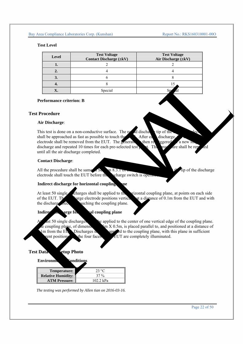
Test Level
Level Test Voltage
Contact Discharge (±kV) Test Voltage
Air Discharge (±kV)
1. 2 2
2. 4 4
3. 6 8
4. 8 15
X. Special Special
Performance criterion: B
Test Procedure
Air Discharge:
This test is done on a non-conductive surface. The round discharge tip of the discharge electrode shall be approached as fast as possible to touch the EUT. After each discharge, the discharge electrode shall be removed from the EUT. The generator is then re-triggered for a new single discharge and repeated 10 times for each pre-selected test point. This procedure shall be repeated until all the air discharge completed. Contact Discharge:
All the procedure shall be same as Section 8.3.1 of EN 61000-4-2, except that the tip of the discharge electrode shall touch the EUT before the discharge switch is operated. Indirect discharge for horizontal coupling plane
At least 50 single discharges shall be applied to the horizontal coupling plane, at points on each side of the EUT. The discharge electrode positions vertically at a distance of 0.1m from the EUT and with the discharge electrode touching the coupling plane. Indirect discharge for vertical coupling plane
At least 50 single discharges shall be applied to the center of one vertical edge of the coupling plane. The coupling plane, of dimensions 0.5m X 0.5m, is placed parallel to, and positioned at a distance of 0.1m from the EUT. Discharges shall be applied to the coupling plane, with this plane in sufficient different positions that the four faces of the EUT are completely illuminated.
Test Data and Setup Photo
Environmental Conditions
Temperature: 23 C Relative Humidity: 37 %
ATM Pressure: 102.2 kPa
The testing was performed by Allen tian on 2016-03-16.

FINAL
Bay Area Compliance Laboratories Corp. (Kunshan) Report No.: RKS160310001-00O
Page 23 of 50
Test Mode : Opterating
Table 1: Electrostatic Discharge Immunity (Air Discharge)
EN 61000-4-2 Test Points Location
Test Levels-2 kV +2 kV -4 kV +4 kV -8 kV +8 kV -15 kV +15 kV X
Surface ( 6 points) A A A A A A / / /
/ / / / / / / / / /
/ / / / / / / / / /
/ / / / / / / / / /
Table 2: Electrostatic Discharge Immunity (Direct Contact)
EN 61000-4-2 Test Points
Location Test Levels
-2 kV +2 kV -4 kV +4 kV -6 kV +6 kV -8 kV +8 kV XSurface ( 1 points) A A A A / / / / /
Table 3: Electrostatic Discharge Immunity (Indirect Contact HCP)
EN 61000-4-2 Test Points
Location Test Levels
-2 kV +2 kV -4 kV +4 kV -6 kV +6 kV -8 kV +8 kV X
Front Side A A A A / / / / /
Back Side A A A A / / / / /
Left Side A A A A / / / / /
Right Side A A A A / / / / /
Table 4: Electrostatic Discharge Immunity (Indirect Contact VCP)
EN 61000-4-2 Test Points
Location Test Levels
-2 kV +2 kV -4 kV +4 kV -6 kV +6 kV -8 kV +8 kV X
Front Side A A A A / / / / /
Back Side A A A A / / / / /
Left Side A A A A / / / / /
Right Side A A A A / / / / /

FINAL
Bay Area Compliance Laboratories Corp. (Kunshan) Report No.: RKS160310001-00O
Page 24 of 50
Test point as follows: Represents Air Direct Discharge Represents Contact Discharge
FINAL
Bay Area Compliance Laboratories Corp. (Kunshan) Report No.: RKS160310001-00O
Page 25 of 50
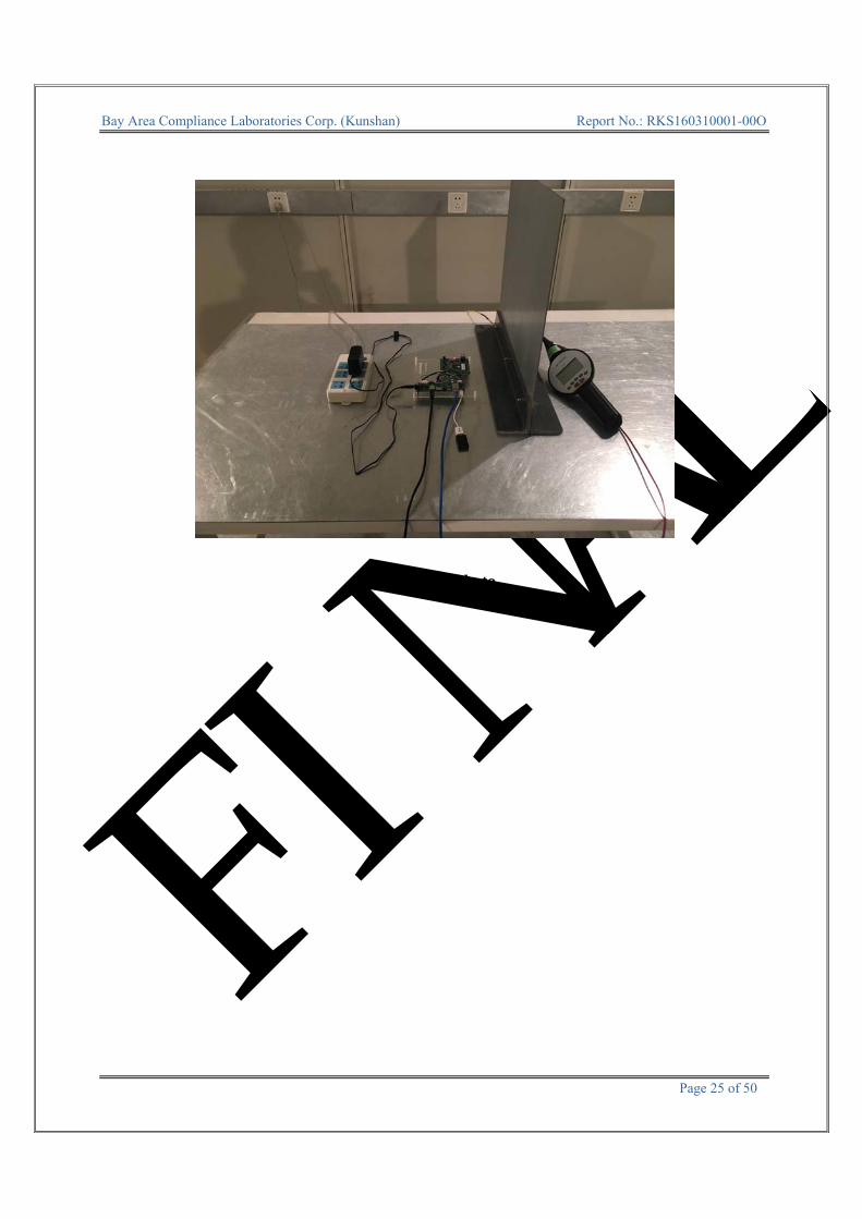
Test Setup Photo

FINAL
Bay Area Compliance Laboratories Corp. (Kunshan) Report No.: RKS160310001-00O
Page 26 of 50
7.2 - ELECTRICAL FAST TRANSIENT IMMUNITY Measurement Uncertainty Ulab (measurement uncertainty of lab) and UEN (measurement uncertainty of EN 61000-4-4) please refer to the following:
Parameter UEN Ulab
Rise time tr 6.20% 6.20%
Peak voltage value Vp 8.60% 8.60%
Voltage pulse width tw 5.90% 5.90%
Test Equipment
Manufacturer Description Model Serial Number Calibration
Date Calibration Due Date
EM TEST Auto Transformer MV2616 V0939105172 2015-11-12 2016-11-12
EM TEST Ultra Compact
Generator UCS500-M4 303279 2016-02-19 2017-02-19
EM TEST EFT Clamp CDN 125 30088 2016-03-03 2017-03-03
* Statement of Traceability: Bay Area Compliance Laboratories Corp. (Kunshan) attests that all calibrations have been performed in accordance to requirements that traceable to National Primary Standards and International System of Units (SI).
Test System Setup Test Standard
ETSI EN 301 489-1 V1.9.2 (2011-09)/ EN 61000-4-4: 2004+A1:2010 AC Mains: Test level 2 at 1 kV
Ground Reference Plane
EUT
Wooden Table
Ground Reference Plane
Grounding C
able
80cm
10cm

FINAL
Bay Area Compliance Laboratories Corp. (Kunshan) Report No.: RKS160310001-00O
Page 27 of 50
Test Level
Open Circuit Output Test Voltage ±10%
Level On Power Supply Lines On I/O (Input/Output) Signal data and control lines
1 0.5 kV 0.25 kV 2 1 kV 0.5 kV3 2 kV 1 kV4 4 kV 2 kVX Special Special
Performance Criterion: B Test Procedure The EUT was arranged for Power Line Coupling and for I/O Line Coupling through a capacitive clamp, where applicable. (Note: The I/O coupling test using a capacitive clamp is performed on the I/O interface cables that are longer in length than 3 meters.) A metal ground plane 2.4 meter by 2.0 meter was placed between the floor and the table and is connected to the earth by a 2.0 meter ground rod. The ground rod is connected to the test facility’s electrical earth. Test Data and Setup Photo
Environmental Conditions
Temperature: 22.2 oC
Relative Humidity: 34%
ATM Pressure: 102.2 kPa
* The testing was performed by Allen tian on 2016-03-16.
Test Mode : Opterating
EN61000-4-4 Test Points
Test Levels (kV)
+0.5 -0.5 +1.0 -1.0 +2.0 -2.0 +3.0 -3.0
AC mains power input ports
L1 A A A A / / / /
L2 A A A A / / / /
Earth / / / / / / / /
L1+L2 A A A A / / / /
L1 + Earth / / / / / / / /
L2 + Earth / / / / / / / /
L1+L2+Earth / / / / / / / /
Signal ports / / / / / / / / /

FINAL
Bay Area Compliance Laboratories Corp. (Kunshan) Report No.: RKS160310001-00O
Page 28 of 50
Test Setup Photo

FINAL
Bay Area Compliance Laboratories Corp. (Kunshan) Report No.: RKS160310001-00O
Page 29 of 50
7.2 - RF COMMON MODE
Measurement Uncertainty Ulab (measurement uncertainty of lab) and UEN (measurement uncertainty of EN 61000-4-6) please refer to the following:
Parameter UEN Ulab
CDN calibration process 1.27 dB 1.27 dB
CDN test process 1.36 dB 1.36 dB
Test Equipment
Manufacturer Description Model Serial NumberCalibration
Date Calibration Due Date
Signal Generator
Agilent 8648C 3537A01810 2015-06-19 2016-06-18
SPANAWAVE Power Amplifier PAS-000023-
25 AA00566 2015-11-12 2016-11-12
Dressler Attenuator ATT 6/75 510020010004 2015-11-12 2016-11-12
EM TEST CDN CDN M2/M3 0707-13 2015-11-12 2016-11-12
COM-POWER CDN CDN M2-25 511034 2015-11-12 2016-11-12
* Statement of Traceability: Bay Area Compliance Laboratories Corp. (Kunshan) attests that all calibrations have been performed in accordance to requirements that traceable to National Primary Standards and International System of Units (SI).
Test Setup 10 cm Test Standard
EN 301 489-1 V1.9.2/EN 61000-4-6: 2009 Test level 2 at 3 V (r.m.s.), 0.15 MHz ~ 80 MHz,
Test Level
Level Voltage Level (r.m.s.)(U0)
1 1 2 3 3 10 X Special
Performance Criterion: A
Wooden TableSG
CDN EUT

FINAL
Bay Area Compliance Laboratories Corp. (Kunshan) Report No.: RKS160310001-00O
Page 30 of 50
Test Procedure 1) Let the EUT work in test mode and test it. 2) The EUT are placed on an insulating support 0.1 m high above a ground reference plane. CDN
(coupling and decoupling device) is placed on the ground plane about 0.3 m from EUT. Cables between CDN and EUT are as short as possible, and their height above the ground reference plane shall be between 30 and 50 mm (where possible).
3) The disturbance signal described below is injected to EUT through CDN. 4) The EUT operates within its operational mode(s) under intended climatic conditions after power on. 5) The frequency range is swept from 150 kHz to 80 MHz using 3V signal level, and with the disturbance
signal 80% amplitude modulated with a 1 kHz sine wave. 6) The rate of sweep shall not exceed 1.5*10-3decades/s. Where the frequency is swept incrementally, the
step size shall not exceed 1% of the start and thereafter 1% of the preceding frequency value. 7) Recording the EUT operating situation during compliance testing and decide the EUT immunity criterion. Test Data and Setup Photo
Environmental Conditions
Temperature: 22.2 oC
Relative Humidity: 34%
ATM Pressure: 102.2 kPa
* The testing was performed by Allen tian on 2016-03-16.
Test Mode: Opterating
Table 1: AC mains power input port Frequency range: 150 kHz to 80 MHz
■Modulated: Amplitude 80%, 1 kHz sine wave □ Unmodulated □ Other: Severity Level: 3 V Unmodulated, r.m.s
Level Voltage Level (e.m.f.)
U0 Pass Fail
1 1 / / 2 3 A / 3 10 / / X Special / /

FINAL
Bay Area Compliance Laboratories Corp. (Kunshan) Report No.: RKS160310001-00O
Page 31 of 50
Test Setup photo

FINAL
Bay Area Compliance Laboratories Corp. (Kunshan) Report No.: RKS160310001-00O
Page 32 of 50
7.2 - SURGES, LINE TO LINE AND LINE TO GROUND Test Equipment
Manufacturer Description Model Serial Number Calibration
Date Calibration Due Date
EM TEST Auto Transformer MV2616 V0939105172 2015-11-12 2016-11-12
EM TEST Ultra Compact
Generator UCS500-M4 303279 2016-02-19 2017-02-19
* Statement of Traceability: Bay Area Compliance Laboratories Corp. (Kunshan) attests that all calibrations have been performed in accordance to requirements that traceable to National Primary Standards and International System of Units (SI).
Test System Setup Test Standard
ETSI EN 301 489-1 V1.9.2 (2011-09) / EN 61000-4-5: 2006 AC Mains: L-N: Test level 2 at 1 kV
Test Level
Level Open Circuit Output Test Voltage ±10%
1 0.5 kV2 1 kV3 2 kV4 4 kVX Special
Performance Criterion: B
Ground Reference Plane
EUT
Wooden Table
Ground Reference Plane
Grounding C
able
80cm
10cm

FINAL
Bay Area Compliance Laboratories Corp. (Kunshan) Report No.: RKS160310001-00O
Page 33 of 50
Test Procedure
1) For line to line coupling mode, provide a 0.5 kV 1.2/50us voltage surge (at open-circuit condition). 2) At least 5 positive and 5 negative (polarity) tests with a maximum 1/min repetition rate are conducted
during test. 3) Different phase angles are done individually. 4) Record the EUT operating situation during compliance test and decide the EUT immunity criterion for
above each test. Test Data and Setup Photo
Environmental Conditions
Temperature: 22.2 oC
Relative Humidity: 34%
ATM Pressure: 102.2 kPa
* The testing was performed by Allen tian on 2016-03-16.
Test Mode: Opterating
Table 1: AC mains power input port
Level Voltage Poll Path Pass Fail
1 0.5kV ± L-N A /
2 1kV ± L-N A /
3 2kV ± / / /
4 4kV ± / / /

FINAL
Bay Area Compliance Laboratories Corp. (Kunshan) Report No.: RKS160310001-00O
Page 34 of 50
Test Setup photo
FINAL
Bay Area Compliance Laboratories Corp. (Kunshan) Report No.: RKS160310001-00O
Page 35 of 50
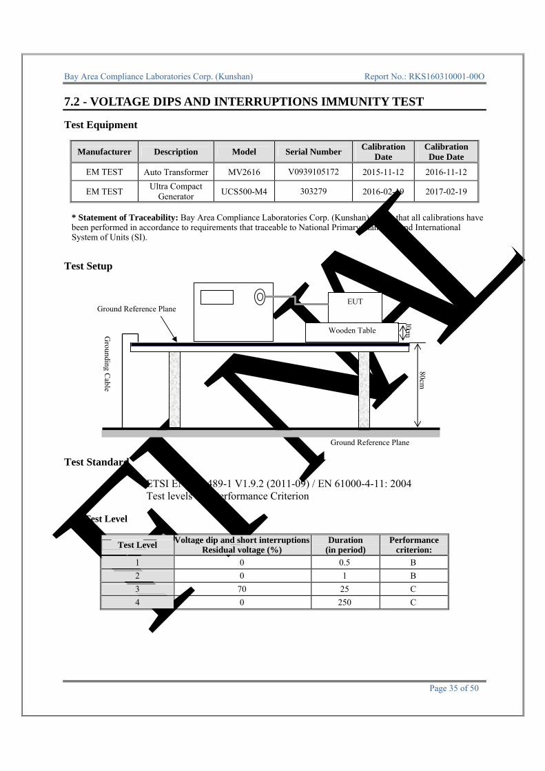
7.2 - VOLTAGE DIPS AND INTERRUPTIONS IMMUNITY TEST Test Equipment
Manufacturer Description Model Serial Number Calibration
Date Calibration Due Date
EM TEST Auto Transformer MV2616 V0939105172 2015-11-12 2016-11-12
EM TEST Ultra Compact
Generator UCS500-M4 303279 2016-02-19 2017-02-19
* Statement of Traceability: Bay Area Compliance Laboratories Corp. (Kunshan) attests that all calibrations have been performed in accordance to requirements that traceable to National Primary Standards and International System of Units (SI).
Test Setup Test Standard
ETSI EN 301 489-1 V1.9.2 (2011-09) / EN 61000-4-11: 2004 Test levels and Performance Criterion
Test Level
Test Level Voltage dip and short interruptions
Residual voltage (%) Duration
(in period) Performance
criterion:
1 0 0.5 B
2 0 1 B
3 70 25 C
4 0 250 C
Ground Reference Plane
EUT
Wooden Table
Ground Reference Plane
Grounding C
able
80cm
10cm

FINAL
Bay Area Compliance Laboratories Corp. (Kunshan) Report No.: RKS160310001-00O
Page 36 of 50
Test Procedure 1) The interruption is introduced at selected phase angles with specified duration. 2) Record any degradation of performance. Test Data and Setup Photo
Environmental Conditions
Temperature: 22.2 oC
Relative Humidity: 34%
ATM Pressure: 102.2 kPa
* The testing was performed by Allen tian on 2016-03-16.
Test Mode: Opterating
Level
Voltage dip and short interruptions
Residual voltage (%)
Td (Periods) Phase Angle N Result
1 0 0.5 0/90/180/270 3 A
2 0 1 0/90/180/270 3 A
3 70 25 0/90/180/270 3 A
4 0 250 0/90/180/270 3 C

FINAL
Bay Area Compliance Laboratories Corp. (Kunshan) Report No.: RKS160310001-00O
Page 37 of 50
Test Setup photo

FINAL
Bay Area Compliance Laboratories Corp. (Kunshan) Report No.: RKS160310001-00O
Page 38 of 50
7.1 - HARMONIC CURRENT EMISSIONS According to EN 61000-3-2:2006 + A1:2009 + A2:2009 section 7: Equipment with a rated power of 75 W or less, other than discharge lighting equipment, are not included in this standard.
FINAL
Bay Area Compliance Laboratories Corp. (Kunshan) Report No.: RKS160310001-00O
Page 39 of 50
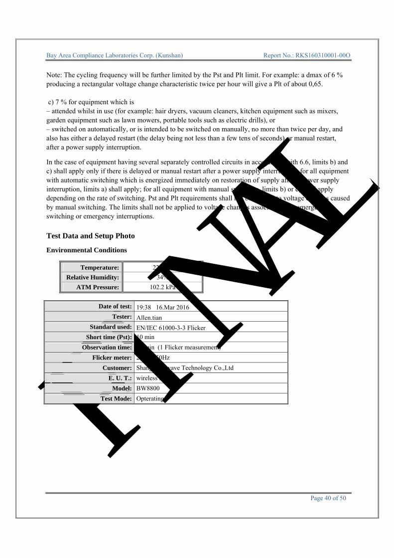
7.1 - VOLTAGE FLUCTUATION AND FLICKER Test Equipment
Manufacturer Description Model Serial Number Calibration
Date Calibration Due Date
EM TEST Harmonic & Flicker Analyzer
DPA 500N 303278 2015-04-09 2016-04-09
EM TEST AC Power Source ACS500N 5611 2015-04-09 2016-04-09
* Statement of Traceability: Bay Area Compliance Laboratories Corp. (Kunshan) attests that all calibrations have been performed in accordance to requirements that traceable to National Primary Standards and International System of Units (SI).
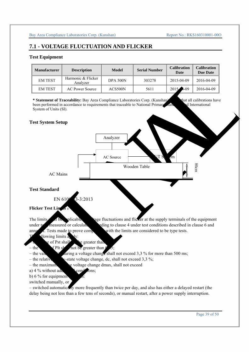
Test System Setup Test Standard
EN 61000-3-3:2013 Flicker Test Limits :
The limits shall be applicable to voltage fluctuations and flicker at the supply terminals of the equipment under test, measured or calculated according to clause 4 under test conditions described in clause 6 and annex A. Tests made to prove compliance with the limits are considered to be type tests. The following limits apply: – the value of Pst shall not be greater than 1,0; – the value of Plt shall not be greater than 0,65; – the value of d(t) during a voltage change shall not exceed 3,3 % for more than 500 ms; – the relative steady-state voltage change, dc, shall not exceed 3,3 %; – the maximum relative voltage change dmax, shall not exceed a) 4 % without additional conditions; b) 6 % for equipment which is: switched manually, or – switched automatically more frequently than twice per day, and also has either a delayed restart (the delay being not less than a few tens of seconds), or manual restart, after a power supply interruption.
AC Mains
AC Source EUT System
Wooden Table
80cm
Analyzer
FINAL
Bay Area Compliance Laboratories Corp. (Kunshan) Report No.: RKS160310001-00O
Page 40 of 50
Note: The cycling frequency will be further limited by the Pst and Plt limit. For example: a dmax of 6 % producing a rectangular voltage change characteristic twice per hour will give a Plt of about 0,65. c) 7 % for equipment which is – attended whilst in use (for example: hair dryers, vacuum cleaners, kitchen equipment such as mixers, garden equipment such as lawn mowers, portable tools such as electric drills), or – switched on automatically, or is intended to be switched on manually, no more than twice per day, and also has either a delayed restart (the delay being not less than a few tens of seconds) or manual restart, after a power supply interruption. In the case of equipment having several separately controlled circuits in accordance with 6.6, limits b) and c) shall apply only if there is delayed or manual restart after a power supply interruption; for all equipment with automatic switching which is energized immediately on restoration of supply after a power supply interruption, limits a) shall apply; for all equipment with manual switching, limits b) or c) shall apply depending on the rate of switching. Pst and Plt requirements shall not be applied to voltage changes caused by manual switching. The limits shall not be applied to voltage changes associated with emergency switching or emergency interruptions. Test Data and Setup Photo Environmental Conditions
Temperature: 22.2 C
Relative Humidity: 34%
ATM Pressure: 102.2 kPa
Date of test: 19:38 16.Mar 2016
Tester: Allen.tian
Standard used: EN/IEC 61000-3-3 Flicker
Short time (Pst): 10 min
Observation time: 10 min (1 Flicker measurement)
Flicker meter: 230V / 50Hz
Customer: Shanghai Bwave Technology Co.,Ltd
E. U. T.: wireless modul
Model: BW8800
Test Mode: Opterating

FINAL
Bay Area Compliance Laboratories Corp. (Kunshan) Report No.: RKS160310001-00O
Page 41 of 50
Maximum Flicker results
EUT values Limit Result
Pst 0.028 1.00 PASS
Plt 0.028 0.65 PASS
dc [%] 0.009 3.30 PASS
dmax [%] 0.072 4.00 PASS
dt [s] 0.000 0.50 PASS
Test Setup photo

FINAL
Bay Area Compliance Laboratories Corp. (Kunshan) Report No.: RKS160310001-00O
Page 42 of 50
EXHIBIT A - CE PRODUCT LABELING Proposed CE Label Format Specifications: The marking set out above must be affixed to the apparatus or to its data plate and have a minimum
height of 5 mm. The elements should be easily readable and indelible. They may be placed anywhere on the apparatus case or in its battery compartment. No tool should be needed to view the marking. 1313: 4 digit notified body number
Note: The label should contain the below content: ① The name of the manufacturer or the person responsible for placing the apparatus on the market ② Type ③ Batch and/or serial numbers
Proposed Label Location on EUT

FINAL
Bay Area Compliance Laboratories Corp. (Kunshan) Report No.: RKS160310001-00O
Page 43 of 50
EXHIBIT C - EUT PHOTOGRAPHS
EUT –Top View
EUT –Bottom View

FINAL
Bay Area Compliance Laboratories Corp. (Kunshan) Report No.: RKS160310001-00O
Page 44 of 50
EUT –Front View
EUT –Rear View
FINAL
Bay Area Compliance Laboratories Corp. (Kunshan) Report No.: RKS160310001-00O
Page 45 of 50
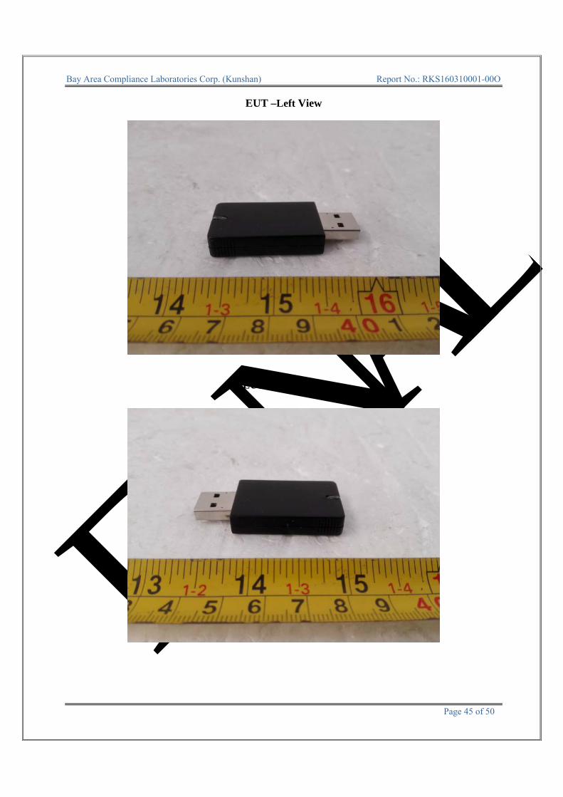
EUT –Left View
EUT –Right View

FINAL
Bay Area Compliance Laboratories Corp. (Kunshan) Report No.: RKS160310001-00O
Page 46 of 50
EUT –Cover off View
EUT – Main Board Top View
FINAL
Bay Area Compliance Laboratories Corp. (Kunshan) Report No.: RKS160310001-00O
Page 47 of 50
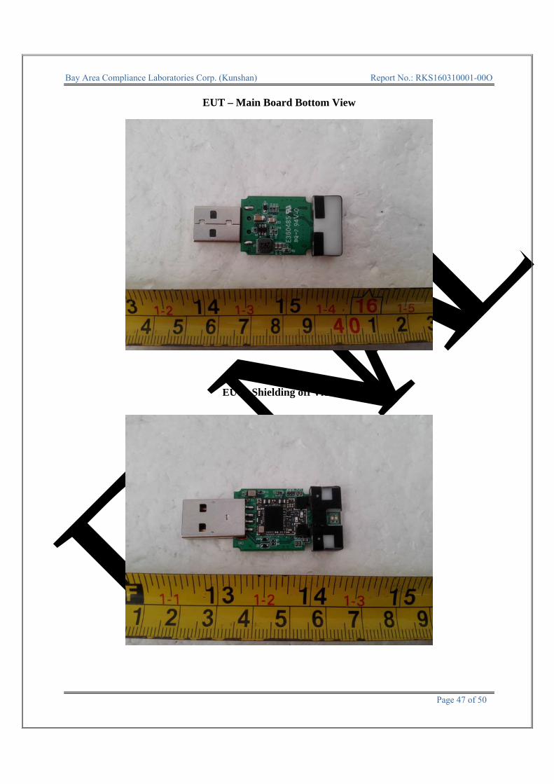
EUT – Main Board Bottom View
EUT –Shielding off View
FINAL
Bay Area Compliance Laboratories Corp. (Kunshan) Report No.: RKS160310001-00O
Page 48 of 50
EXHIBIT C – TEST SETUP PHOTOGRAPHS
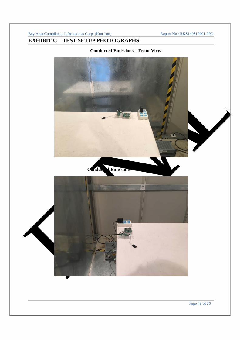
Conducted Emissions – Front View
Conducted Emissions - Side View

FINAL
Bay Area Compliance Laboratories Corp. (Kunshan) Report No.: RKS160310001-00O
Page 49 of 50
Radiated Emissions –Front View (Below 1GHz)
Radiated Emissions –Rear View (Below 1GHz)
FINAL
Bay Area Compliance Laboratories Corp. (Kunshan) Report No.: RKS160310001-00O
Page 50 of 50
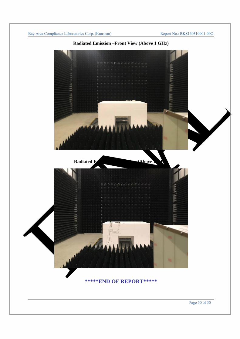
Radiated Emission –Front View (Above 1 GHz)
Radiated Emission –Rear View (Above 1 GHz)
*****END OF REPORT*****


![ETSI EN 301 489-15 V2.1...ETSI 7 ETSI EN 301 489-15 V2.1.1 (2016-11) 1 Scope The present document, together with ETSI EN 301 489-1 [1], covers the assessment of commercially available](https://img.dokumen.tips/doc/110x75/5f2db8b1264c1574960889e1/etsi-en-301-489-15-v21-etsi-7-etsi-en-301-489-15-v211-2016-11-1-scope-the.jpg)


![Draft ETSI EN 301 489-9 V2.1...2000/02/01 · ETSI 6 Draft ETSI EN 301 489-9 V2.1.0 (2016-09) 1 Scope The present document, together with ETSI EN 301 489-1 [1], covers the assessment](https://img.dokumen.tips/doc/110x75/606a6768dee68d6bb84c1cb0/draft-etsi-en-301-489-9-v21-20000201-etsi-6-draft-etsi-en-301-489-9-v210.jpg)