Embed Size (px)
Citation preview

New
pre
sent
atio
n -
see
His
tory
box
ETSI ETR 148
TECHNICAL January 1995
REPORT
Source: ETSI TC-BTC Reference: DTR/BTC-04001
ICS: 33.080
Key words: PTN, architecture, interworking, multimedia, LAN, MAN, ISDN, B-ISDN, ATM, frame relay
Private Telecommunication Network (PTN);Integrated services architecture for high speed private networks
ETSIEuropean Telecommunications Standards Institute
ETSI Secretariat
Postal address: F-06921 Sophia Antipolis CEDEX - FRANCEOffice address: 650 Route des Lucioles - Sophia Antipolis - Valbonne - FRANCEX.400: c=fr, a=atlas, p=etsi, s=secretariat - Internet: [email protected]
Tel.: +33 92 94 42 00 - Fax: +33 93 65 47 16
Copyright Notification: No part may be reproduced except as authorized by written permission. The copyright and theforegoing restriction extend to reproduction in all media.
© European Telecommunications Standards Institute 1995. All rights reserved.
Page 2ETR 148: January 1995
Whilst every care has been taken in the preparation and publication of this document, errors in content,typographical or otherwise, may occur. If you have comments concerning its accuracy, please write to"ETSI Editing and Committee Support Dept." at the address shown on the title page.

Page 3ETR 148: January 1995
Contents
Foreword .......................................................................................................................................................5
1 Scope .........................................................................................................................................................7
2 References .................................................................................................................................................7
3 Definitions...................................................................................................................................................9
4 Abbreviations............................................................................................................................................10
5 Application scenarios and their characteristics.........................................................................................115.1 LAN interconnection ....................................................................................................................115.2 High speed data transfer .............................................................................................................125.3 Video communication in real-time ...............................................................................................135.4 Video in store-and-forward ..........................................................................................................135.5 Multimedia communication..........................................................................................................135.6 Audio communication..................................................................................................................14
6 Network technologies ...............................................................................................................................146.1 Transmission technologies..........................................................................................................15
6.1.1 Plesiochronous Digital Hierarchy (PDH) ...................................................................156.1.2 Synchronous Digital Hierarchy (SDH).......................................................................156.1.3 Higher order leased lines ..........................................................................................15
6.2 Switching/relaying technologies ..................................................................................................156.2.1 64 kbit/s ISDN...........................................................................................................156.2.2 Ethernet, CSMA/CD - ISO/IEC 8802-3 .....................................................................166.2.3 Token ring - ISO/IEC 8802-5 ....................................................................................166.2.4 Fibre Distributed Data Interface (FDDI) - ISO 9314..................................................176.2.5 Integrated Services LAN (ISLAN) - IEEE 802.9........................................................186.2.6 Distributed Queue Dual Bus (DQDB) - ISO/IEC 8802-6...........................................186.2.7 Asynchronous Transfer Mode (ATM)........................................................................196.2.8 Frame relay...............................................................................................................20
7 Evaluation of switching/relaying technologies ..........................................................................................21
8 Reference configurations..........................................................................................................................218.1 Components of a Corporate Telecommunication Network (CTN) ..............................................218.2 General network configuration ....................................................................................................218.3 Specific reference configurations ................................................................................................22
8.3.1 ISDN reference configuration ...................................................................................228.3.2 B-ISDN reference configuration................................................................................228.3.3 MAN reference configuration ....................................................................................228.3.4 PISN reference configuration....................................................................................238.3.5 HS-PISN reference configuration .............................................................................23
8.4 Reference network connections..................................................................................................238.4.1 Local connection .......................................................................................................238.4.2 Metropolitan area connection....................................................................................238.4.3 Wide-area connection (moderate size).....................................................................248.4.4 Wide-area connection (maximum size) ....................................................................24
9 CPN functional model...............................................................................................................................24
10 Interworking scenarios and requirements ..............................................................................................2610.1 Interworking scenario for LAN interconnection .........................................................................2610.2 Interworking scenario for high speed data transfer ...................................................................2710.3 Interworking scenario for video communication in real-time .....................................................27

Page 4ETR 148: January 1995
10.4 Interworking scenario for multimedia communication .............................................................. 2710.5 Interworking requirements ........................................................................................................ 27
Annex A: Considerations for the evaluation of switching/relaying technologies ......................................... 29
Annex B: Example configuration of LAN interconnection ........................................................................... 30
History ......................................................................................................................................................... 31

Page 5ETR 148: January 1995
Foreword
This ETSI Technical Report (ETR) has been prepared by the Business TeleCommunications (BTC)Technical Committee of the European Telecommunications Standards Institute (ETSI).
ETRs are informative documents resulting from ETSI studies which are not appropriate for EuropeanTelecommunication Standard (ETS) or Interim European Telecommunication Standard (I-ETS) status. AnETR may be used to publish material which is either of an informative nature, relating to the use or theapplication of ETSs or I-ETSs, or which is immature and not yet suitable for formal adoption as an ETS oran I-ETS.
This ETR, which describes an integrated services architecture for high speed private networks, is mainlyintended to serve as a framework document for the work of STC BTC4 "Private Network Aspects of HighSpeed Business Communication". Not all aspects of high speed private networks can be covered in thisETR in order to provide this baseline document in a timely manner. In particular, network managementand signalling issues will require further documents.

Page 6ETR 148: January 1995
Blank page

Page 7ETR 148: January 1995
1 Scope
This ETSI Technical Report (ETR) describes an Integrated Services Architecture for High Speed PrivateNetworks.
This ETR identifies relevant application scenarios and their characteristics for high speed communicationin private networks.
Current network technologies are described and evaluated in terms of their suitability for the relevantapplication scenarios. It should be noted that only subnetwork technologies are described; theidentification of network layer protocols for the interconnection of subnetworks is outside the scope of thisETR.
Based on the evaluation results reference configurations are developed and interworking requirementsare derived.
Although it is understood that signalling and management aspects are essential in the context of anintegrated services architecture, these topics are not covered in this ETR. The same applies to wirelesscommunications. Additional documents will have to be developed that are dedicated to these topics.
2 References
For the purposes of this ETR, the following references apply:
[1] ETS 300 211: "Network Aspects (NA); Metropolitan Area Network (MAN);Principles and architecture".
[2] ETS 300 217: "Network Aspects; Connectionless Broadband Data Service(CBDS)".
[3] ETS 300 278: "Network Aspects (NA); Support of existing services withguaranteed constant bit rate and specified transfer delay on Metropolitan AreaNetwork (MAN)".
[4] ITU-T Recommendation F.811: "Broadband connection-oriented bearerservice".
[5] ITU-T Recommendation F.812: "Broadband connectionless data bearerservice".
[6] ITU-T Recommendation G.103: "Hypothetical reference connections".
[7] ITU-T Recommendation G.702: "Digital hierarchy bit rates".
[8] ITU-T Recommendation G.703: "Physical/electrical characteristics ofhierarchical digital interfaces".
[9] ITU-T Recommendation G.704: "Synchronous frame structures used at primaryand secondary hierarchy levels".
[10] ITU-T Recommendation G.707: "Synchronous digital hierarchy bit rates".
[11] ITU-T Recommendation G.708: "Network node interface for the synchronousdigital hierarchy".
[12] ITU-T Recommendation G.709: "Synchronous multiplexing structure".
[13] ITU-T Recommendation H.244: "Revised channel aggregation standardharmonized with ISO/IEC committee draft".
[14] ITU-T Recommendation I.121: "Broadband aspects of ISDN".

Page 8ETR 148: January 1995
[15] ITU-T Recommendation I.150: "B-ISDN asynchronous transfer mode functionalcharacteristics".
[16] ITU-T Recommendation I.211: "B-ISDN service aspects".
[17] ITU-T Recommendation I.233.1: "ISDN frame mode bearer services (FMBS) -ISDN frame relaying bearer service".
[18] ITU-T Recommendation I.311: "B-ISDN general network aspects".
[19] ITU-T Recommendation I.320: "ISDN protocol reference model".
[20] ITU-T Recommendation I.321: "B-ISDN protocol reference model and itsapplication".
[21] ITU-T Recommendation I.324: "ISDN network architecture".
[22] ITU-T Recommendation I.327: "B-ISDN functional architecture".
[23] ITU-T Recommendation I.361: "B-ISDN ATM layer specification".
[24] ITU-T Recommendation I.362: "B-ISDN ATM adaptation layer (AAL) functionaldescription".
[25] ITU-T Recommendation I.363: "B-ISDN ATM adaptation layer (AAL)specification".
[26] ITU-T Recommendation I.364: "Support of broadband connectionless dataservice on B-ISDN".
[27] ITU-T Recommendation I.365.1: "Frame relaying service specific convergencesublayer (FR-SSCS)".
[28] ITU-T Recommendation I.370: "Congestion management for the ISDN framerelaying bearer service".
[29] ITU-T Recommendation I.371: "Traffic control and congestion control inB-ISDN".
[30] ITU-T Recommendation I.372: "Frame mode bearer service network-to-networkinterface requirements".
[31] ITU-T Recommendation I.411: "ISDN user-network interfaces - referenceconfigurations".
[32] ITU-T Recommendation I.413: "B-ISDN user-network interface".
[33] ITU-T Recommendation I.431: "Primary rate user-network interface - Layer 1specification".
[34] ITU-T Recommendation I.555: "Frame relaying bearer service interworking".
[35] ITU-T Recommendation Q.922: "ISDN data link layer specification for framemode bearer services".
[36] ITU-T Recommendation Q.931: "Digital subscriber Signalling System No.1(DSS1) - ISDN user-network interface layer 3 specification for basic call control".
[37] ITU-T Recommendation Q.933: "Digital subscriber Signalling System No.1(DSS1) - Signalling specification for frame mode bearer service".

Page 9ETR 148: January 1995
[38] ITU-T Recommendation Q.2931: "Broadband Integrated Services DigitalNetwork (B-ISDN) - Digital subscriber Signalling System No.2 (DSS2) - User-network interface layer 3 specification for basic call/connection control".
[39] ISO/IEC 8802-3: "Information technology - Local and metropolitan areanetworks - Part 3: Carrier sense multiple access with collision detection(CSMA/CD) access method and physical layer specifications".
[40] ISO/IEC 8802-5: "Information processing systems - Local and metropolitan areanetworks - Part 5: Token ring access method and physical layer specifications".
[41] ISO/IEC 8802-6: "Information processing systems - Telecommunications andinformation exchange between systems - Local and metropolitan area networks- Part 6: Distributed Queue Dual Bus (DQDB) access method and physical layerspecifications".
[42] ISO 9314: "Information processing systems - Fiber distributed data interface(FDDI)".
[43] ISO/IEC 11579-1: "Information technology - Telecommunications andinformation exchange between systems - Private Integrated Services Network -Part 1: Reference configuration for PISN Exchanges (PINX)".
[44] ISO/IEC DIS 11801: "Information technology - Generic cabling for customerpremises cabling".
[45] ISO/IEC DIS 13871: "Information technology - Telecommunications andinformation exchange between systems - Local and metropolitan area networks- Private Integrated Services Network - Digital channel aggregation".
[46] IEEE 802.9: "Integrated Services LAN (ISLAN) interface at the MAC and PHYlayers".
[47] IEEE 802.6.h: "Isochronous service on a Distributed Queue Dual Bus (DQDB)subnetwork of a Metropolitan Area Network (MAN)".
3 Definitions
Only those terms are defined in this clause which cannot easily be found in other standards or wheredifferent definitions exist. All other terms are used according to their definition in relevant standards. Thedefinitions for Local Area Network (LAN), Metropolitan Area Network (MAN) technologies can be found inthe ISO/IEC, IEEE 802 and ETSI standards that are listed in clause 2. The Integrated Services DigitalNetwork (ISDN) and Broadband Integrated Services Digital Network (B-ISDN) terms are defined in therelevant ITU-T Recommendations.
Access Facility (AF): The network segment that connects the CPN to the MSS.
Access Node (AN): A node providing access to the public network.
Broadband Integrated Services Private Branch eXchange (B-ISPBX): An exchange of a B-PISN thatis located on the customer premises.
Broadband Private Integrated Services Network (B-PISN): Connection oriented private broadbandISDN, with the possibility to include non-ISDN parts within the context of (non-ISDN) bearer capabilities.
Customer Premises Equipment (CPE): The equipment part of a CTN (i.e. a CTN excluding the privatewiring or cabling).
Customer Premises Network (CPN): That part of a CTN that is located on a single premises.
Corporate Telecommunication Network (CTN): Private network, connection oriented and/orconnectionless, of any kind of technology, e.g., LAN, MAN, nx64 kbit/s ISDN or B-ISDN.

Page 10ETR 148: January 1995
High-Speed Private Integrated Services Network (HS-PISN): That part of a CTN that provides high-speed, connection oriented and/or connectionless, of any kind of technology suitable for high speedtransmission.
Interconnecting Network (ICN): That part of a CTN that interconnects two CPNs in the context of anintegrated scenario.
Integrated Services Centrex (ISCTX): An implementation of a PINX located on a third party premises.
Integrated Services LAN (ISLAN): LAN that provides asynchronous and isochronous services.
Integrated Services Private Branch eXchange (ISPBX): An implementation of a PINX located on thecustomer premises.
Intervening Network (IVN): That part of a CTN that interconnects two CPNs in the context of an overlayscenario.
leased lines: The telecommunications facilities provided by a public telecommunications network thatprovide defined transmission characteristics between network termination points and that do not includeswitching functions that the user can control (e.g. on demand switching).
MAN Switching System (MSS): A collection of functions that provides high-speed switching in the publicMAN.
Network Termination type 2 (NT2): A functional group between S and T reference points in ISDNnetworks.
private B-ISDN: A private network providing B-ISDN services.
Private Integrated Services Network (PISN): Connection-oriented private 64 kbit/s ISDN with thepossibility to include non-ISDN parts within the context of (non-ISDN) bearer capabilities.
Private Integrated Services Network eXchange (PINX): An exchange of the PISN.
Terminal Equipment (TE): The equipment attached to a network, via which the user accesses thenetwork services.
Transit Link (TL): A link within the public network.
Transit Node (TN): A node within the public network.
Virtual Private Network (VPN): The emulation of transit node functionality and/or end node functionalityby public network equipment.
4 Abbreviations
For the purposes of this ETR, the following abbreviations apply:
10BASE2 10 Mbit/s Baseband 200 m segment length10BASE5 10 Mbit/s Baseband 500 m segment length10BASE-F 10 Mbit/s Baseband Fiber optic cable10BASE-T 10 Mbit/s Baseband Twisted pair cableAAL ATM Adaptation LayerAF Access FacilityAN Access NodeATM Asynchronous Transfer ModeB-ISDN Broadband Integrated Services Digital NetworkB-ISPBX Broadband Integrated Services Private Branch eXchangeB-PISN Broadband Private Integrated Services NetworkCBDS Connectionless Broadband Data ServiceCBR Constant Bitrate VideoCPE Customer Premises Equipment

Page 11ETR 148: January 1995
CPN Customer Premises NetworkCSMA/CD Carrier Sense Multiple Access with Collision DetectionCTN Corporate Telecommunication NetworkDQDB Distributed Queue Dual BusFDDI Fiber Distributed Data InterfaceFOIRL Fiber Optic Inter Repeater LinkHS-PISN High-Speed Private Integrated Services NetworkICN Interconnecting NetworkISCTX Integrated Services CentrexISDN Integrated Services Digital NetworkISLAN Integrated Services LANISPBX Integrated Services Private Branch eXchangeIVN Intervening NetworkLAN Local Area NetworkLAPD Link Access Procedure on the D-channelMAC Medium Access ControlMAN Metropolitan Area NetworkMSS MAN Switching SystemNT2 Network Termination type 2ONP Open Network ProvisionPDH Plesiochronous Digital HierarchyPDU Protocol Data UnitPINX Private Integrated Services Network eXchangePISN Private Integrated Services NetworkSDH Synchronous Digital HierarchySONET Synchronous Optical NetworkSTM-n Synchronous Transport Module level nTE Terminal EquipmentTL Transit LinkTN Transit NodeVBR Variable Bitrate VideoVPN Virtual Private Network
5 Application scenarios and their characteristics
In accordance with the scope of this ETR and the terms of reference of STC BTC4, the following fiveapplications are considered as most relevant in the context of high speed communication in privatenetworks:
- LAN interconnection;- high speed data transfer;- video communication in real-time;- video in store-and-forward;- multimedia communication.
A more complete set of possible broadband services and applications in a Corporate TelecommunicationNetwork (CTN) is contained in ITU-T Recommendation I.211 [16].
5.1 LAN interconnection
LAN interconnection is not an application from the end-user's point of view, but it is an importantapplication of high speed communication networks. Typical LAN applications today are office systems,where most of the traffic results from data exchange between terminals (PCs, workstations) and servers.The data exchange between terminals over wide areas, i.e. attached to geographically separate LANs, isoften restricted to occasional electronic mail messages. Whilst the attached terminals often communicatewith each other at relatively low speeds, the LAN data rate needs to be high to accommodate theaggregate data from many terminals. Although Integrated services LANs and high speed LANs (≥ 100 Mbit/s) are being developed, they are not yet significantly deployed. Therefore, in the context of LANInterconnection, only well established LAN types are considered.
Single LAN traffic characteristics:
- data transmission (note 1);

Page 12ETR 148: January 1995
- data rates 1 to 20 Mbit/s (note 2);- bursty traffic;- small volume data transfer in variable length frames;- broadcast and multicast (group addressing).
NOTE 1: LANs have been designed for data transmission only. Whilst data transmissionremains dominant, conversational voice and video transmission capabilities areemerging.
NOTE 2: Although there are networks in use with data rates of the order of 100 Mbit/s, (e.g.FDDI, see subclause 6.2.4), they are mostly used as LAN interconnecting networks,not as single LANs.
Interconnected LAN traffic characteristics:
- the traffic characteristics of interconnected LANs are basically the same as the trafficcharacteristics of single LANs. Depending on the configuration the data rates of theinterconnected LANs are usually in the same range as for a single LAN, but in somecircumstances may be greater.
Service requirements of LAN interconnection:
- transfer of small volume data in variable length data units (frames);- support of connectionless mode traffic;- data rates equal to or greater than LAN data rates (note 3);- low undetected error rate (LAN applications are based on an undetected error rate of
5×10-14 per octet of Medium Access Control (MAC) service data unit);- support of group addressing;- variable delay is acceptable.
NOTE 3: The data rate of the interconnecting network may even be below the data rates of theindividual LANs for availability or economic reasons. This may result in degradedperformance.
5.2 High speed data transfer
This application provides high speed data communication between end-users. Examples of high speeddata transfer are file transfer, e.g. for CAD/CAM applications, remote image data base access and dataexchange between super-computers, e.g. for weather forecasting.
Traffic characteristics:
- data transmission only;- data rates > 1 Mbit/s;- high volume data transfer in variable length frames or packets;- point-to-point communication (note 1).
NOTE 1: Multicasting will be less common than in a typical LAN application.
Service requirements:
- transfer of high volume data in variable length data units (frames or packets);- peak data rates > 1 Mbit/s (note 2);- low undetected error rate;- group addressing (note 3);- variable delay is acceptable.
NOTE 2: High volume concurrent data transfer from several sources may be required, resultingin these high peak data rates.
NOTE 3: Group addressing will be required if multicasting is supported.

Page 13ETR 148: January 1995
5.3 Video communication in real-time
Real-time video communication requires low delay and low delay variation of the transporting network.This type of video communication encompasses conversational video and video distribution.
Traffic characteristics:
- video transmission;- data rates up to 140 Mbit/s per video connection, depending on the video coding. Widely
used data rates today are 64 kbit/s, 128 kbit/s, 384 kbit/s, 1,5 Mbit/s, 2 Mbit/s, 7 to 10 Mbit/sand 45 Mbit/s. Also depending on the coding, the data rate may be constant (CBR) orvariable (VBR);
- continuous bit stream;- point-to-multipoint (note), multipoint-to-multipoint.
NOTE: Point-to-multipoint communication will be required, but may be realized by meansother than multicasting.
Service requirements:
- transfer of high volume data in continuous bit streams;- peak data rates between 64 kbit/s and 140 Mbit/s (for CBR, mean data rate equals peak data
rate);- support of point-to-multipoint and multipoint-to-multipoint communication;- low delay and low delay variation.
5.4 Video in store-and-forward
Video in store-and-forward is tolerant of significant delays and delay variance by means of buffering. Videoin store-and-forward encompasses video mail and video retrieval.
Traffic characteristics:
- video transmission;- data rates up to 140 Mbit/s per video connection, depending on the video coding. Widely
used data rates today are 64 kbit/s, 128 kbit/s, 384 kbit/s, 1,5 Mbit/s, 2 Mbit/s, 7 to 10 Mbit/s,and 45 Mbit/s. Also depending on the coding, the data rate may be constant (CBR) orvariable (VBR);
- continuous bit stream;- point-to-multipoint (note 1), multipoint-to-multipoint.
NOTE 1: Point-to-multipoint communication will be required, but may be realized by meansother than multicasting.
Service requirements:
- transfer of high volume data in continuous bit streams;- peak data rates between 64 kbit/s and 140 Mbit/s (For CBR, mean data rate equals peak
data rate);- support of point-to-multipoint and multipoint-to-multipoint communication;- significant and variable delay is acceptable (note 2).
NOTE 2: Terminal buffering may be required to compensate for delay variance.
5.5 Multimedia communication
Multimedia communication in this context means end-to-end communication, i.e. "to the desk", involvingmore than one type of information, e.g. text&graphics, audio&video, voice&data&video. The differentinformation types may be transferred via different connections. In a multipoint call there may be differentcombinations of information types between different combinations of participants, e.g. in a three partyvoice call there could also be a file transfer between two parties. When the information types are related toeach other, e.g. voice and video, synchronization has to take place. The combination of information types

Page 14ETR 148: January 1995
may change during the call, e.g. during a voice conversation the parties agree to jointly work on adocument. This results in changes of data rate during the call.
Traffic characteristics:
Multimedia communication combines the appropriate traffic characteristics, depending on the typesof information to be exchanged. For example, if text, graphics, still images and real-time video areexchanged, the traffic characteristics listed in subclauses 5.1 to 5.4 will appear in the combineddata transfer. In addition to the traffic characteristics listed in subclauses 5.1 to 5.4, the trafficrequirements for audio communication have to be defined in order to provide for all types ofmultimedia communication (see subclause 5.6).
Service requirements:
The multimedia service requirements will be a combination of the service requirements that arederived from the information types involved in the multimedia communication. Since therequirements for data and video communication are already summarized in the previous sections,only the requirements for voice communication are listed in subclause 5.6. In addition there is aneed for synchronization of related information types. This implies that the most stringentrequirement of the involved information types has to be met by all of those information types.
5.6 Audio communication
Although audio communication is not within the scope of this ETR, the traffic characteristics and theservice requirements of audio communication are required in the context of multimedia communication.
Traffic characteristics:
- voice transmission;- data rates up to 384 kbit/s (note 1);- continuous bit stream;- (point-to-multipoint (note 2)).
NOTE 1: Data rates less than 64 kbit/s can be achieved by using voice compression. On theother hand data rates higher than 64 kbit/s, e.g. 384 kbit/s may be used for thetransmission of high quality audio.
NOTE 2: Point-to-multipoint communication may be required for conference calls.
Service requirements:
- transfer of data in continuous bit streams;- data rates up to 384 kbit/s;- (support of point-to-multipoint communication);- very low delay and low delay variations (note 3).
NOTE 3: The delay requirements for conversational voice are more stringent than for real-timevideo.
6 Network technologies
It has been shown in clause 5 that the application scenarios which are relevant for high speedcommunication in private networks lead to different service requirements. These requirements can beused as a basis for the identification of suitable existing services and the selection of networktechnologies.
In the following, a brief overview of relevant transmission and switching/relaying technologies is given. Itshould be noted, that as far as functionality in terms of OSI layers is concerned, only subnetworktechnologies are described. The identification of network layer protocols for the interconnection ofsubnetworks is outside the scope of this ETR.

Page 15ETR 148: January 1995
6.1 Transmission technologies
The following transmission systems are used both as communication services on their own (leased lines)or to carry Distributed Queue Dual Bus (DQDB) and Asynchronous Transfer Mode (ATM) protocols. Allother switching/relaying technologies use their own transmission systems.
6.1.1 Plesiochronous Digital Hierarchy (PDH)
The PDH was developed in 1965. "Plesiochronous" means "almost synchronous". Each clock is allowed acertain range of speeds. The multiplexer reads each tributary into a buffer. It reads out of the buffer at thehighest allowed clock speed and, when there are no bits in the input buffer (because the bits are arrivingaccording to a slower clock), it adds a "stuffing bit" to "stuff" the signal up to the higher clock speed. It alsohas a mechanism to signal to the demultiplexer that it has performed stuffing, and the demultiplexer mustknow which bit to throw out.
The European hierarchy of PDH systems is:
E1 2,048 Mbit/s;E2 8,448 Mbit/s;E3 34,368 Mbit/s;E4 139,264 Mbit/s.
ETSI STC BTC2 is charged with the standardization for the connection characteristics and interfacepresentation for the following Open Network Provision (ONP) minimum set leased lines:
64 kbit/s with octet integrity;2 048 kbit/s unstructured and structured leased lines.
6.1.2 Synchronous Digital Hierarchy (SDH)
The new method of multiplexing, "SDH" in Europe, Synchronous Optical Network (SONET) in NorthAmerica, was developed in the early 1980s. The basic time constant of 8 000 frames per second ispreserved in SDH. What is transmitted in these 125 µs is represented in a rectangle. All information iscollected in bytes and no longer in bits. The bytes are transmitted one row at a time. The tributaries to amultiplexer each have a frame that is not aligned in time with the other tributaries, nor with the frame ofthe output stream. To resolve this problem, the SDH multiplexer calculates a pointer that tells where in theSynchronous Transport Module level 1 (STM-1) frame it has placed the tributary frame.
STM-1 155,520 Mbit/s;STM-4 622,080 Mbit/s;STM-16 2488,320 Mbit/s.
6.1.3 Higher order leased lines
ETSI STC BTC2 is charged with the standardization of the connection characteristics and interfacepresentation of the following higher order leased lines:
34 Mbit/s structured and unstructured leased lines;140 Mbit/s structured and unstructured leased lines.
These leased lines will use the structure developed by ETSI STC TM3 for use in an SDH environment.
6.2 Switching/relaying technologies
6.2.1 64 kbit/s ISDN
Since it can be assumed that the characteristics of 64 kbit/s ISDN are well known, only the major featureswill be listed for completeness sake:
- end-to-end digital connectivity;- 2B+D (basic rate access);- 30B+D (primary rate access);- out of band signalling (D-channel).

Page 16ETR 148: January 1995
Service characteristics (isochronous service only, note 1):
- continuous bit stream;- isochronous (constant low delay);- data rates 64 kbit/s, 384 kbit/s, 1 536 kbit/s, 1 920 kbit/s (B, H0, H11, H12),
n×64 kbit/s (notes 2 and 3);- connection oriented service;- permanent and on-demand service provision;- no broadcast or multicast capability.
NOTE 1: ISDN also offers packet- and frame-mode services.
NOTE 2: The n×64 kbit/s bearer service (n = 2 to 128) can provide a similar bandwidth asachieved by aggregating the bitstreams of a corresponding number of individual64 kbit/s channels (see ISO/IEC DIS 13871 [45] and draft ITU-T RecommendationH.244 [13]).
NOTE 3: The name "multiple-rate bearer service" has been adopted by ETSI TC NA to describethe n×64 kbit/s bearer service.
Relevant standards (note 4): [19], [31], [33], [36]
NOTE 4: This list is by no means complete; only a few of the most relevant ISDN standards arelisted.
6.2.2 Ethernet, CSMA/CD - ISO/IEC 8802-3
Carrier Sense Multiple Access with Collision Detection (CSMA/CD) controls access to the medium bymeans by which two or more stations share a common transmission medium. To transmit, a station waits(defers) for a quiet period on the medium (that is, no other station is transmitting) and then sends theintended message in bit-serial form. If, after initiating a transmission, the message collides with that ofanother station, then each transmitting station intentionally sends a few additional bytes to ensurepropagation of the collision throughout the system. The station then remains silent for a random amount oftime (back-off) before attempting to transmit again. The CSMA/CD LAN technology is defined for use on50 Ω coaxial cable (10BASE5 and 10BASE2), on unshielded twisted pair (10BASE-T) and on fibre opticcable (FOIRL and 10BASE-F).
Service characteristics:
- transfer of small volume data in variable length data units;- variable delay;- transmission rates 1 Mbit/s, 10 Mbit/s and 100 Mbit/s (note);- connectionless service;- no guaranteed bandwidth;- broadcast and multicast capability.
NOTE: 100 Mbit/s CSMA/CD has not yet been standardized, but it is an accepted IEEE 802project. In addition, a project for a demand-priority protocol, using the CSMA/CDProtocol Data Unit (PDU) format over voice grade twisted pair cabling at 100 Mbit/shas been accepted as IEEE 802 project.
Relevant standards: [39], [44]
6.2.3 Token ring - ISO/IEC 8802-5
In a token ring, stations are serially connected to form a logical ring over which data and controlinformation is transmitted and received.
Access to this ring is controlled by a signalling sequence referred to as the "token" which circulates aroundthe ring from station to station.

Page 17ETR 148: January 1995
A station desiring to transmit waits until it receives a token. The station changes the token to a start-of-message, transmits its message and, upon completion of the message, releases a new token for use byother stations on the ring.
Token ring is defined for operation on shielded and unshielded twisted pair medium at data rates of4 Mbit/s and 16 Mbit/s. In addition, token ring may operate using fibre optic cable.
Service characteristics:
- transfer of small volume data in variable length data units;- variable delay;- transmission Rates 4, 16 Mbit/s (note);- connectionless service;- no guaranteed bandwidth;- broadcast and multicast capability;- priority mechanism.
NOTE: The demand-priority protocol is designed in such a way that token ring protocol dataunits can be transported as well as CSMA/CD PDUs at 100 Mbit/s.
Relevant standards: [40], [44]
6.2.4 Fibre Distributed Data Interface (FDDI) - ISO 9314
FDDI is a 100 Mbit/s LAN. The FDDI protocol is based on a token ring access method. The FDDI MACuses a timed token rotation protocol to control access to the medium. Under this protocol, each stationmeasures the time that has elapsed since a token was last received. The initialization proceduresestablish the target token rotation time equal to the lowest value that is bid by any of the stations. Twoclasses of service are defined:
- synchronous service allows use of a token whenever MAC has synchronous frames queuedfor transmission (note 1);
- asynchronous service allows use of a token only when the time since a token last wasreceived has not exceeded the established target token rotation time.
NOTE 1: The meaning of "synchronous" in this context is completely different from the"synchronous" technology in subclause 6.1. "Synchronous service" in FDDI means thata station can rely on a guaranteed minimum response time.
Multiple levels of priority for asynchronous frames may be provided within a station by specifying additional(more restrictive) time thresholds for token rotation.
FDDI-II is an upward-compatible enhancement of the basic FDDI that adds a circuit-switched capability tothe packet capability.
FDDI had originally been specified for use on optical fibre (single-mode and multi-mode). Recently,specifications for use of shielded and unshielded twisted pair have been added.
Service characteristics:
- transmission rate 100 Mbit/s;- connectionless service:
- variable delay;- transfer of small volume data in variable length data units;- no guaranteed bandwidth (but guaranteed minimum response time for synchronous
service);- broadcast and multicast capability;- priority mechanism;
- isochronous service (only provided by FDDI-II):- continuous bit stream;- constant low delay;- data rates 8 kbit/s, 16 kbit/s, 32 kbit/s, 64 kbit/s, 384 kbit/s, 1,536 Mbit/s, 1,920 Mbit/s,
2,048 Mbit/s and 6,144 Mbit/s;

Page 18ETR 148: January 1995
connection oriented service;permanent service provision (note);no broadcast or multicast capability.
NOTE 2: The use of signalling protocols, e.g. ITU-T Recommendations Q.93x, is possible, butoutside the scope of ISO 9314 [42].
Relevant standards (note 3): [42]
NOTE 3: ISO 9314 [42] consists of several parts. Additional specifications for single mode fibrephysical medium dependent, copper physical medium dependent and hybrid ringcontrol (FDDI-II) have been added recently. However, for simplicity reasons, thestandards are not listed separately.
6.2.5 Integrated Services LAN (ISLAN) - IEEE 802.9
ISLAN has been standardized by IEEE 802.9 [46]. It describes a time division multiplexing based interfaceat 4,096 Mbit/s and 20,48 Mbit/s, over unshielded twisted pair. By means of a set of different channels (B-channels, C-channel, D-channel and P-channel) it is capable of supporting voice, data as well as video-traffic. Therefore, ISLAN is suitable for the provision of multimedia services. The interface specificationcan be used in combination with existing PBX- and LAN-technologies.
Service characteristics:
- transmission rates 4,096 Mbit/s and 20,48 Mbit/s (note 1);- connectionless service:
- variable delay;- transfer of small volume data in variable length data units;- no guaranteed bandwidth;- broadcast and multicast capability;- priority mechanism;
- isochronous service:- continuous bit stream;- constant low delay;- data rates 64 kbit/s, n×64 kbit/s;- connection oriented service;- permanent and on-demand service provision (note 2);- no broadcast or multicast capability.
NOTE 1: An option with 16,384 Mbit/s ("IsoEnet") has been accepted as project IEEE 802.9a. Adraft specification is available.
NOTE 2: The use of signalling protocols based on ITU-T Recommendations Q.93x is onlyrecommended in IEEE 802.9 [46].
Relevant standards: [46]
6.2.6 Distributed Queue Dual Bus (DQDB) - ISO/IEC 8802-6
DQDB is defined to have the capability to work over the local area and to interoperate with the other LANtechnologies.
However, DQDB is more often encountered in the metropolitan area and it introduces the concept of theMAN, where the development of a high speed technology is required to support e.g. connectionless dataservices. For the specification of the corresponding service, the Connectionless Broadband Data Service(CBDS), see ETS 300 211 [1] and ETS 300 217 [2]. Because of the differing environments in which theDQDB MAN will be utilized, a variety of physical layer protocols which make use of existing underlyingtransmission standards have been defined.
DQDB provides a high-speed shared medium access protocol for use over a dual, contra-directional(counter-flowing, unidirectional) bus subnetwork. DQDB provides three types of service:

Page 19ETR 148: January 1995
- connectionless MAC service;- isochronous service;- connection oriented data service.
In order to support these services, two access methods have been defined:
- a queued arbitrated access method with three priority queues for medium arbitration andfixed-length slots for data transfer. Each priority level provides distributed queue access forthe support of connectionless MAC service and connection oriented service. In addition,functions equivalent to the ATM Adaptation Layer (AAL) are provided for the support ofconnectionless MAC service and connection oriented service;
- a pre-arbitrated access method that uses assigned slot positions for the support ofisochronous services.
Service characteristics:
- transmission rates 1,544 (T1), 2,048 (E1), 34,368 (E3), 44,736 (T3), 139,264 (E4), 155,520(STM-1) and 622,080 Mbit/s (STM-4);
- connectionless service:- variable delay;- transfer of data in variable length data units (max. size 9 188 octets);- no guaranteed bandwidth;- broadcast and multicast capability;- priority mechanism (note 1).
- isochronous service:- constant low delay;- continuous bit stream;- variable data rates;- connection oriented service;- semi-permanent service provision (note 2);- multicast capability (dependent on the signalling protocol).
- connection-oriented service:- variable delay;- transfer of data in variable length data units (max. size 65 535 octets);- guaranteed bandwidth;- semi-permanent service provision (note 2);- multicast capability;- priority mechanism.
NOTE 1: In order to ensure fair sharing of bandwidth, only one priority is to be used forconnectionless service.
NOTE 2: The use of signalling protocols based on ITU-T Recommendations Q.293x is possible,but currently outside the scope of ISO/IEC 8802-6 [41].
Relevant standards: [1], [2], [3], [7], [8], [9], [41], [47]
6.2.7 Asynchronous Transfer Mode (ATM)
ATM is the technology for B-ISDN. In ATM, information to be transferred is segmented into a set of fixed-size cells. These "cells" are equivalent to the "slots" of DQDB. Length and structure of cells and slots areidentical in order to ease interworking.
Cells are identified and switched by means of a label in the header (virtual path identifier/virtual channelidentifier). Cells belonging to the same connection may exhibit an irregular recurrence pattern, as cells arefilled according to actual demand.
On top of the ATM layer, AAL functions have been specified for the support of different types of services(e.g. connectionless mode, constant bitrate). In particular, CBDS may be provided on top of ATM with thesame characteristics as on top of DQDB.

Page 20ETR 148: January 1995
Service characteristics:
- transmission rates 1,544 (T1), 2,048 (E1), 34,368 (E3), 44,736 (T3), 51,8 (OC-1), 139,264(E4) , 155,520 (STM-1) and 622,080 Mbit/s (STM-4) (note 1).
- connectionless service (CBDS):- variable delay;- transfer of data in variable length data units (max. size 9 188 octets);- variable bit rate: "maximum allowed sustained information rate" is a subscription option
(access class);- broadcast and multicast capability;
- constant bitrate service:- continuous bit stream;- constant low delay;- multiple data rates;- connection oriented service;- permanent and on-demand service provision (note 2);- multicast capability (dependent on the signalling protocol).
- variable bitrate service:- connection oriented service with end-to-end transport of timing information;- permanent and on-demand service provision (note 2);- multicast capability (dependent on the signalling protocol);
- connection-oriented service:- variable delay;- transfer of data in variable length data units (max. size 65 535 octets);- guaranteed bandwidth;- permanent and on-demand service provision (note 2);- multicast capability.
NOTE 1: Mapping standards for these data rates are available. However, their use has not yetbeen specified at the user-network interface.
NOTE 2: User-network interface signalling protocols based on ITU-T Recommendations Q.93x(Q.293x) are being standardized. Public network node interface signalling protocolsbased on ISUP (B-ISUP) are being standardized.
Relevant standards: [2], [4], [5], [8], [9], [10], [11], [12], [14], [15], [16], [18], [20], [22], [23],[24], [25], [26], [27], [29], [32], [34], [38]
6.2.8 Frame relay
Frame relay provides a connection oriented packet data service. Frame relay can be supported bydifferent network technologies, such as ISDN, ATM, dedicated data networks.
Frame relay uses a layer 2 protocol which is derived from the ISDN Link Access Procedure on theD-channel (LAPD).
Service characteristics:
- connection-oriented service:- data rates 64 kbit/s to 2 Mbit/s (note 1);- variable delay;- transfer of data in variable length data units (max. PDU size negotiable, at least 260
octets);- guaranteed bandwidth;- semi-permanent and on-demand service provision (note 2).
NOTE 1: Provision of frame relay service on 34 Mbit/s transmission systems is underdevelopment.
NOTE 2: In the case of frame relay provision in ISDN (B-ISDN), use of signalling protocol ITU-TRecommendation Q.933 [37] (Q.293x).
Relevant standards: [17], [27], [28], [30], [34], [35]

Page 21ETR 148: January 1995
7 Evaluation of switching/relaying technologies
Table 1 shows an attempt to classify the relevant switching/relaying technologies in terms of theirsuitability for the application scenarios listed in clause 5. The rationale for this attempted classification iscontained in annex A. Based on this rating, interworking scenarios and requirements will be derived (seeclauses 8 to 10). Additionally, geographical limitations will be taken into consideration.
Table 1
LAN inter-connection
High speeddata transfer
Real-timevideo
Video instore-and-
forward
Multimediacommuni-
cation64 kbit/s ISDN (note 1) + + + + +nx64 kbit/s ISDN ++ ++ ++ ++ ++CSMA/CD ++ ++ + + +Token Ring ++ ++ + ++ +FDDI +++ +++ ++ ++ ++FDDI-II ++ +++ +++ +++ +++ISLAN n.a. ++ ++ ++ ++DQDB ++++
(note 2)+++ +++ +++ +++
ATM ++++(note 2)
++++ +++ ++++ +++
Frame relay ++ ++ + + +Legend: + limited suitability
++ suitable+++ more suitable++++ most suitablen.a. not applicable
NOTE 1: The term 64 kbit/s ISDN is used for differentiation from B-ISDN. It encompasses both basicaccess and primary rate access.
NOTE 2: This classification applies only for high data rate implementations (e.g. 155 Mbit/s).
8 Reference configurations
8.1 Components of a Corporate Telecommunication Network (CTN)
A CTN consists of Customer Premises Equipment (CPE) and/or Customer Premises Networks (CPNs)which are located at geographically dispersed locations and are interconnected to provide networkingservices to a defined group of users.
8.2 General network configuration
Different types of networks will be interconnected for the provision of the transport service as basis forend-to-end communication. The general network configuration is intended to encompass all network typesand specific configurations that may be used for end-to-end communication.
TE CPN
CPE
Local Area
AccessNode
Metropolitan
Area
TransitNode
N A T I O N A L
TransitNode
I N T E R N A T I O N A L
TransitNode Node
TransitNodeAccess
Metropolitan
AreaLocal Area
CPN
N A T I O N A L
TE
Figure 1: General network configuration

Page 22ETR 148: January 1995
The access and transit nodes may belong to a public network or they may be part of a CTN, wherecustomer premises networks are interconnected by virtual private networks or intervening networks.
8.3 Specific reference configurations
Specific reference configurations have been standardized by ITU-T, ETSI and ISO/IEC for severalnetwork types that are relevant for high speed communication. The reference configurations provide ascheme for the identification of functional groupings and interfaces which require standardization. In thatrespect, they may be useful in the context of high speed communication.
8.3.1 ISDN reference configuration
The general ISDN reference configuration as depicted in figure 2 is defined in ITU-T RecommendationI.324 [21]. The description of the functional groups is contained in ITU-T Recommendation I.411 [31].
NOTE 1: Within this ETR, the term "customer premises network" is used instead of "customernetwork" in order to avoid ambiguities.
NOTE 2: The general ISDN reference model shown in figure 2 is founded on 64 kbit/s B- and H-channels. It is equally applicable in the case of n×64 kbit/s services derived by channelaggregation in terminal equipment or in the customer network and also by multiratenetwork bearer services.
TE
Customer
e.g. ISPBX
Network
NT2 Public ISDNNetworkPublic
NetworkCustomer
TE
ISLAN
S T T S
NT2
Figure 2: ISDN reference configuration
8.3.2 B-ISDN reference configuration
The B-ISDN reference configuration is defined in ITU-T Recommendation I.327 [22]. In addition to ITU-TRecommendation I.327 [22], descriptions of the functional groups are contained in ITU-TRecommendations I.311 [18] and I.413 [32].
TE
Customer Network
B-ISPBX /private
B-ISDN
Public Network Customer Network
Public B-ISDN TEB-ISBPX/private
B-ISDNS T T SB B B B
Figure 3: B-ISDN reference configuration
8.3.3 MAN reference configuration
The MAN reference configuration and the related functional groups are defined in ETS 300 211 [1].
TE M - NT2
NetworkCustomer
S T
AFLCRF(MSS)
ZTL TCRF
M M M M
MetropolitanArea
Network Transit
Network
Customer
Equipment
Y

Page 23ETR 148: January 1995
TCRF Transit Connection Related FunctionsLCRF Local Connection Related Functions
Figure 4: MAN reference configuration
8.3.4 PISN reference configuration
The PISN reference configuration, in particular the Private Integrated Services Network eXchange (PINX),and the related functional groupings are defined in ISO/IEC 11579-1 [43]. A simplified version is depictedin figure 5.
TE
IVN/ICN
S
CQ
PINX
T
Public ISDN
Figure 5: Simplified reference configuration for PISN
8.3.5 HS-PISN reference configuration
A HS-PISN reference configuration is currently under study in ISO/IEC JTC1/SC6. The results areintended to become ISO/IEC 11579-2. A simplified version of the anticipated reference configuration isgiven in figure 6.
TE
HS-PINX
B-IVN/B-ICNS C Q
T
Public B-ISDNHS-LAN
B
D
B
BB
B
Figure 6: Simplified reference configuration for HS-PISN
8.4 Reference network connections
The following set of reference network connections shall allow for the evaluation of different networktechnologies in terms of their suitability for high speed communication.
The calculation of QOS parameters such as end-to-end delay requires defined reference networkconnections with quantified distances. Therefore, the reference network extension is a prime parameter inthe following reference network connections. Additional parameters may require further refinement of thereference network connections.
8.4.1 Local connection
A reference connection for the local area is depicted in figure 7. The distance on customer premises istaken from ISO/IEC DIS 11801 [44]. The length of access cabling is considered to be negligible (< 100 m).
TE
CPN
ISPBX / TE
ISLAN
4 km
Figure 7: Local area reference connection
8.4.2 Metropolitan area connection
A reference connection for the metropolitan area is depicted in figure 8.

Page 24ETR 148: January 1995
CPN
km
MSS CPN TE
2 50 50 2
TE
Figure 8: Metropolitan area reference connection
8.4.3 Wide-area connection (moderate size)
A reference connection for the wide area with moderate size is depicted in figure 9. The distances aretaken from ITU-T Recommendation G.103 [6].
TE CPN
CPE
Local Area
AccessNode
MetropolitanArea
TransitNode
N A T I O N A L
TransitNode
I N T E R N A T I O N A L
TransitNode Node
TransitNodeAccess
MetropolitanArea
Local Area
CPN
N A T I O N A L
TE
km 500 1000 500
Figure 9: Wide-area reference connection (moderate size)
8.4.4 Wide-area connection (maximum size)
A reference connection for the wide area with maximum size is depicted in figure 10. According to ITU-TRecommendation G.103 [6], this is the longest international connection likely to occur in practice.
TE CPN
CPE
Local Area
AccessNode
MetropolitanArea
TransitNode
N A T I O N A L
TransitNode
I N T E R N A T I O N A L
TransitNode Node
TransitNodeAccess
MetropolitanArea
Local Area
CPN
N A T I O N A L
TE
km 1750 24 000 1750
4 Transit Nodes 5 Transit Nodes 4 Transit Nodes
Figure 10: Wide-area reference connection (maximum size)
9 CPN functional model
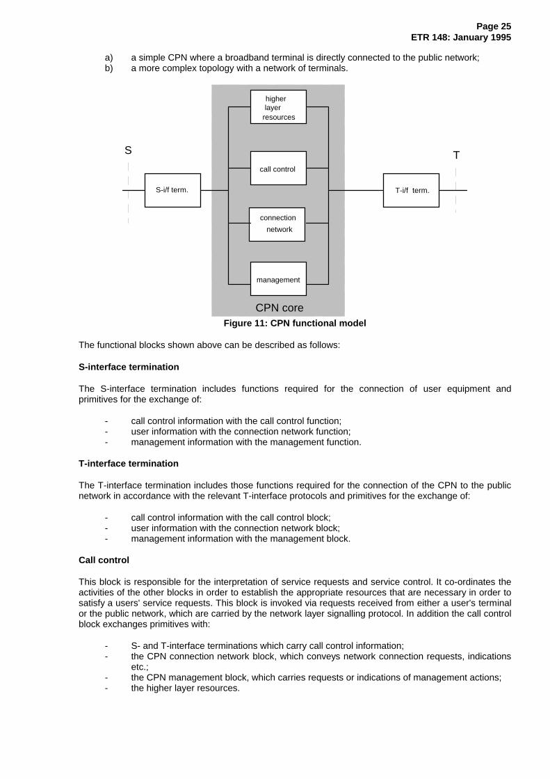
The CPN functional model depicted in figure 11 describes only the simple case of a homogeneous CPN.S- and T-interfaces are used only in the context of ISDN, but should be interpreted here in a wider sense.Therefore this functional model is by no means exhaustive.
However, this functional model covers a variety of different CPN topologies. These can range from:
Page 25ETR 148: January 1995
a) a simple CPN where a broadband terminal is directly connected to the public network;b) a more complex topology with a network of terminals.
CPN core
management
connection
network
call control
higherlayer
resources
S-i/f term. T-i/f term.
S T
Figure 11: CPN functional model
The functional blocks shown above can be described as follows:
S-interface termination
The S-interface termination includes functions required for the connection of user equipment andprimitives for the exchange of:
- call control information with the call control function;- user information with the connection network function;- management information with the management function.
T-interface termination
The T-interface termination includes those functions required for the connection of the CPN to the publicnetwork in accordance with the relevant T-interface protocols and primitives for the exchange of:
- call control information with the call control block;- user information with the connection network block;- management information with the management block.
Call control
This block is responsible for the interpretation of service requests and service control. It co-ordinates theactivities of the other blocks in order to establish the appropriate resources that are necessary in order tosatisfy a users' service requests. This block is invoked via requests received from either a user's terminalor the public network, which are carried by the network layer signalling protocol. In addition the call controlblock exchanges primitives with:
- S- and T-interface terminations which carry call control information;- the CPN connection network block, which conveys network connection requests, indications
etc.;- the CPN management block, which carries requests or indications of management actions;- the higher layer resources.

Page 26ETR 148: January 1995
Connection network
The connection network block is an abstraction of the physical CPN and as such is responsible for theprovision and handling of the physical connections that are necessary to support a call. Requests forconnections, i.e. physical resources, are received from the call control block. The connection networkblock exchanges primitives with:
- the S- and T-interface terminations which convey user information;- the call control block, which conveys network connection requests, indications etc.;- the management block, which conveys information concerning network connections (e.g. the
status of connection invocations).
Management
It is this block which is responsible for those management functions that concern operation,administration, maintenance and provision of the services provided by the CPN (possibly in conjunctionwith the public wide area network). The management block exchanges primitives with:
- the S- and T-interface terminations which convey management information;- the connection network block, which conveys information such as traffic statistics, alarms,
fault logging etc.;- the call control block, which conveys, for example, current call status;- the higher layer resources, e.g. configuration of the management database.
Higher layer resources
This block is responsible for the termination of higher layers (of the protocol stack), provision ofapplication and supplementary services. It could be considered as a set of servers that could be invokedby the call control block in response to a user's request. Higher layer resources model the provision ofsupplementary services and servers where the processing and storage of user information takes place(e.g. message handling).
The higher layer resources block exchanges primitives with:
- the call control block indicating, for example, service requests;- the management block.
10 Interworking scenarios and requirements
Based on the reference configuration for HS-PISN that is depicted in figure 6, interworking scenarios forthe application scenarios described in clause 5 have been derived. These recommended interworkingscenarios are shown in figures 12 to 15. No recommendation is provided for the location of theinterworking function.
An example configuration for LAN interconnection is contained in annex B.
10.1 Interworking scenario for LAN interconnection
The interworking scenario for LAN interconnection is depicted in figure 12. The selection of networktechnologies for the different parts of the network is based on the evaluation in clause 7.
CSMA/CD Higher Order Leased Line
or ATM Public B- ISDN
MAN (DQDB)or DQDB
FDDI
Token Ring
HS-PINX B-IVN/B-ICN
Figure 12: Interworking scenario for LAN interconnection
NOTE: DQDB technology may be used as PINX on customer premises or as MAN. Althoughtoday MANs are based on DQDB technology only, other technologies may be used inthe future.

Page 27ETR 148: January 1995
10.2 Interworking scenario for high speed data transfer
The interworking scenario for high speed data transfer is depicted in figure 13. The selection of networktechnologies for the different parts of the network is based on the evaluation in clause 7.
Higher Order Leased Line
or ATMPublic B- ISDN
MAN (DQDB)or DQDB
FDDIFDDI
DQDB
ATM
High Speed Work Station
High Speed Work Station
High Speed Work Station
HS-PINX B-IVN/B-ICN
Figure 13: Interworking scenario for high speed data transfer
10.3 Interworking scenario for video communication in real-time
The interworking scenario for video communication in real-time is depicted in figure 14. The selection ofnetwork technologies for the different parts of the network is based on the evaluation in clause 7.
Video Higher Order Leased Line
or ATM Public B- ISDN
MAN (DQDB)or DQDB
FDDI-IITerminal FDDI-II
DQDB
ATMVideo
Video
Terminal
Terminal
HS-PINX B-IVN/B-ICN
Figure 14: Interworking scenario for video communication in real-time
10.4 Interworking scenario for multimedia communication
The interworking scenario for multimedia communication is depicted in figure 15. The selection of networktechnologies for the different parts of the network is based on the evaluation in clause 7.
Multimedia Higher Order Leased Line
or ATMPublic B- ISDN
MAN (DQDB)or DQDB
FDDI-IITerminal
FDDI-II
DQDB
ATM
ISLAN
Multimedia
Multimedia
Multimedia
Terminal
Terminal
Terminal
HS-PINX B-IVN/B-ICN
Figure 15: Interworking scenario for multimedia communication

Page 28ETR 148: January 1995
10.5 Interworking requirements
Table 2 summarizes the interworking requirements that can be derived from the interworking scenarios insubclauses 10.1 to 10.4.
Table 2
CSMA/CD TR FDDI FDDI-II ISLAN DQDB DQDB-M ATM B-ISDN HO LLCSMA/CD _
IW IC * IW IC IC IC IC ICTR _
IC * IW IC IC IC IC ICFDDI _ _
IC IW IW IW IW ICFDDI-II _
IC IW IW IW IW ICISLAN _
IC IC IW IW ICDQDB _
IW IW IW ICDQDB-M _
IW IW ICATM _
IW ICB-ISDN _
ICHO LL _
Legend: TR Token RingDQDB-M DQDB used as MANHO LL Higher Order Leased LineIW interworking between TEs (e.g. translation)IC interconnection between networks (e.g. encapsulation)_
not relevant* not required

Page 29ETR 148: January 1995
Annex A: Considerations for the evaluation of switching/relaying technologies
Table 1 has been developed with the following considerations:
Suitability for LAN interconnection
LANs have data rates in the range of 1 to 20 Mbit/s, with the majority using 10 Mbit/s. Therefore, anetwork is better suited for LAN interconnection than another one if its data rate is higher, because theprobability of delays introduced by the interconnecting network is lower.
ISLAN being specified only as an interface for terminal access does not seem to be applicable in thecontext of LAN interconnection.
High speed data transfer
In contrast to LAN interconnection, high speed data transfer means transfer of data with high speed for asignificant amount of time. If this type of traffic has to be accommodated, a switched network like ATM isbetter suited than a shared medium network like FDDI or DQDB where the aggregate bandwidth is equalto the access data rate.
Real-time video
Real-time video requires both relatively high data rates and isochronous capability.
Therefore, neither 64 kbit/s ISDN nor packet oriented data LANs are very well suited for real-time videotransmission.
Multimedia communication
The rating with respect to multimedia communication was derived as the lowest rating of the other threeapplications, which in essence comprise the components of multimedia communication.
Relationship between 64 kbit/s ISDN and nx64 kbit/s ISDN
n×64 kbit/s ISDN offers a higher data rate to a specific application as even the primary rate access of64 kbit/s ISDN.
Relationship between FDDI and FDDI-II
According to the standardization, FDDI-II implies that FDDI as such is available as well. However, sinceFDDI-II means that there is an isochronous component, the bandwidth that is available for packet orienteddata traffic is reduced. Therefore, FDDI-II is less suitable for packet LAN interconnection than FDDI.

Page 30ETR 148: January 1995
Annex B: Example configuration of LAN interconnection
Figure B.1 depicts an example configuration of LAN Interconnection.
CSMA/CD
MAN (DQDB)FDDI
Token Ring
FDDI
CSMA/CD
Token Ring
HS-PINX HS-PINXB-IVN
Figure B.1

Page 31ETR 148: January 1995
History
Document history
January 1995 First Edition
January 1996 Converted into Adobe Acrobat Portable Document Format (PDF)