Embed Size (px)
Citation preview

DEPARTMENT OF THE ARMY ETL 1110-3-512 U.S. Army Corps of Engineers CECW-CE Washington, DC 20314-1000 Technical Letter No. 1110-3-512 30 September 2015
EXPIRES 30 September 2020
Engineering and Design ARMY AIRFIELD AND HELIPORT MARKINGS
1. Purpose. This Engineering Technical Letter (ETL) provides guidance and criteria for marking U.S. Army airfields and heliports. It gives the minimum level of markings necessary for paved surfaces of airfield runways, taxiways, helipads, and the surfaces of obstructions. This document provides direction for marking roadways, vehicular traffic routes on airfields, and airfield service roads. 2. Applicability. All Department of Defense (DoD) / Army (DA) organizations responsible for planning and design of Army airfields. For Army airfields owned and controlled by an authority other than the Department of Defense (DoD), see Joint Use Facilities paragraph below. 3. Distribution Statement. Approved for public release; distribution is unlimited. 4. References. Appendix B contains a list of references used in this ETL. 5. General Information. Pavement markings are provided to enable and enhance safe and informed aircraft and vehicle operation on the airfield. They must be prominent for maximum effectiveness and uniform configuration so they are clearly understood. Do not place locally devised non-standard markings. They could confuse aviators and ground personnel. Such practices can cause runway incursions and/or accidents. 6. Marking Criteria Precedence.
a. The required marking criteria for Army airfields/heliports are stated in this ETL.
b. The marking criteria precedence used shall be based on more stringent airfield/aircraft criteria.
c. In those instances where the military criteria does not adequately capture a certain
requirement, Federal Aviation Administration (FAA) criteria, AC 150/5340-1, may be used. For example FAA criteria has a larger or additional marking that is required for increased emphasis.

ETL 1110-3-512 30 Sep 15
2
d. If the marking does not meet military or FAA criteria, it will be considered a non-standard marking, which requires U. S. Army Aeronautical Service Agency (USAASA) approval. 7. Joint Use Facilities. a. Joint Use Facilities within the United States and its Territories. These type facilities are where a written agreement between the US Military and a local government agency authorize use of the military runways for a public transportation. FAA marking criteria is allowed on the civil portion of Army facilities partially/fully funded by FAA. However, Army markings are required on all other facilities and Army markings will be used if a mixing of standards may create confusion. b. Joint Use Facilities Outside United States and its Territories. All construction outside of the United States is also governed by Status of Forces Agreements (SOFA), Host Nation Funded Construction Agreements (HNFA), and in some instances, Bilateral Infrastructure Agreements (BIA.) Therefore, the acquisition team must ensure compliance with the more stringent of the UFC, the SOFA, the HNFA, and the BIA, as applicable. If a written agreement exists between the host nation and DoD that requires application of North Atlantic Treaty Organization (NATO), International Civil Aviation Organization (ICAO) standards, those standards shall apply as stipulated within the agreement. For cases where a Status of Forces Agreement (SOFA) specifically requires international standards, use ICAO Annex 14, Volume I, Aerodromes (for fixed wing runways) or Annex 14, Volume II, Heliports (for rotary wing helipads and runways), as appropriate. c. Unmanned Aircraft Systems (UAS). ETL 1110-3-510 provides guidance and criteria for marking runways and ancillary movement areas that support operations of US Army UAS. 8. Waiver to Marking Criteria and Standards. a. Installation Design Agent. The installation’s design agent, aviation representative (Safety Officer and Airfield Manager) and Director of Public works DPW Master Planner: (1) Jointly prepares/initiates waiver requests. (2) Submits requests through the installation to the ACOM/ASCC/DRU/ARNG (3) Maintains a complete record of all waivers requested and their disposition (approved or disapproved). A list of waivers to be requested and those approved for a project should also be included in the project design analysis prepared by the design agent, aviation representative, or DPW Master Planner. b.. ACOM/ASCC/DRU/ARNG. The ACOM/ASCC/DRU/ARNG:

ETL 1110-3-512 30 Sep 15
3
(1) Ensures that all required coordination has been accomplished.
(2) Ensures that the type of waiver requested is clearly identified as either “Temporary” or “Permanent.” Temporary waivers are for a specified period during which additional actions to mitigate the situation must be initiated to fully comply with criteria or to obtain a permanent waiver. Follow-up inspections are necessary to ensure that mitigative actions proposed for each Temporary Waiver granted have been accomplished. “Permanent Waivers” are required where no further mitigative actions are intended or necessary. (3) Review waiver requests and forward all viable requests to the U. S. Army Aeronautical Service Agency (USAASA) for action at: U. S. Army Aeronautical Services Agency (USAASA) ATTN: DAMO-AV-A 9325 Gunston Road, Suite N319 Fort Belvoir, VA 22060-5582 c. U.S. Army Aeronautical Services Agency (USAASA). USAASA formulates a consolidated position and makes the final determination on all waiver requests for Army airfield and heliport marking criteria. USAASA coordinates the following reviews for the waiver request: (1) Air traffic control assessment by U.S. Army Air Traffic Services Command (ATSCOM). (2) Safety and risk assessment by U.S. Army Combat Readiness Center (USACRC). (3) Technical engineering review by Transportation Systems Center (TSC). d. Contents of Waiver Requests. Each request must contain the following information. (1) Reference to the specific standard and/or criterion to be waived by publication paragraph, and page. (2) Complete justification for noncompliance with the marking criteria and/or design standards. Demonstrate that noncompliance will provide an acceptable level of safety, economics, durability and quality for meeting the Army mission. This would include reference to special studies made to support the decision. Specific justification for waivers to criteria and allowances must be included as follows: (a) When specific site conditions (physical and functional constraints) make compliance with existing criteria impractical and/or unsafe. (b) When deviation(s) from criteria fall within a reasonable margin of safety and do not impair construction of long range facility requirements.

ETL 1110-3-512 30 Sep 15
4
(c) When marking that does not conform to criteria is the only alternative to meet mission requirements. Evidence of analysis and efforts taken to follow criteria and standards must be documented and referenced. (3) The rationale for the waiver request, including specific impacts upon assigned mission, safety, and/or environment. (4) Operational Factors. Include information on the following existing and/or proposed operational factors used in the assessment: (a) Mission urgency (b) All aircraft by type and operational characteristics (c) Density of aircraft operations at each air operational facility (d) Facility capability Visual Flight Rules (VFR) or Instrument Flight Rules (IFR) (e) Use of self-powered parking versus manual parking (f) Safety of operations & DD Form 2977 (risk management) (g) Existing Navigational Aids (NAVAIDS) (5) Documentation. Record all alternatives considered, their consequences, necessary mitigation efforts, and evidence of coordination. d. Toning Down. Overseas Army Installation Commanders may also propose the toning down of pavement markings as described within NATO STANAG 3534. Obtain these from the Defense Printing Service Detachment Office (DPSDO) at: DPSDO - Customer Service Standardization Documents Order Desk 700 Robbins Avenue Philadelphia PA 19111-5094 Facsimile: Commercial (215) 697-2978 (DSN 442-2978) e. Additional Markings. Army Installation Commanders may also authorize additional markings for runways, taxiways, and aprons, based on necessity, however these additional non-standard markings must be approved by USAASA through the ACOM/ASCC/ DRU/ARNG IAW coordinating procedures in paragraph 6(b)(3) above.
ETL 1110-3-512 30 Sep 15
f. Obstruction Markings. ACOM/ ASCC/DRU and ARNG may waive obstruction markings for objects that penetrate the airfield imaginary surfaces from those listed in Appendix A, paragraph A-6 Marking of Obstructions to Air Navigation.
g. Marking a runway, taxiway, apron for a secondary use: A waiver must be submitted for any secondary-use type markings on a runway, taxiway or apron for other than what it is designed for, such as landing zone (LZ) markings for C130/C-17s on a Class A/B runway, flight deck landing practice pad (FLDP) on apron/taxiway for Navy helicopters, or UAS runway on apron/taxiway. The waiver will be submitted JAW this ETL. These secondary-use markings must meet the applicable DoD design criteria established for the specific type of operation. Careful consideration must be taken on the impact to existing aviation missions. Also, document the evaluation of the impact and/or additional risk associated with any existing airfield waivers or facilities built to previous design criteria where these type of operations were not previously considered. As necessary, obtain approval to update/revise existing design criteria waivers or submit new waivers for non-compliant condition prior to marking the runway/taxiway/apron ' with these secondary markings.
9. Implementation. This ETL is effective immediately.
3 Appendices: App A - Army Airfield and
Heliport Markings App B - References App C - Definitions
~ AMES C. DALTON, P.E. hief, Engineering and Construction
U.S. Army Corps of Engineers
5
..

ETL 1110-3-512 30 Sep 15
6
THIS PAGE INTENTIONALLY LEFT BLANK

ETL 1110-3-512 30 Sep 15
A-1
APPENDIX A
Army Airfield and Heliport Markings
A-1. Materials, Application Rates, and Colors. a. Materials and Application Rates. (1) Paint. Mark flexible and rigid pavements with lead free pavement-marking paints, available under Federal Specification TT-P-1952E, Paint, Traffic and Airfield Marking, Waterborne. Select Type I, “Ten Minute No Pick-up Time” or Type II, “Fast Dry, High Humidity Formula. Apply glass beads to the paint immediately after application of paint to incorporate retroreflective properties into the markings. (2) Permanent Painted Markings. Apply markings at 12 to 14 mils (0.31 to 0.36 mm) wet-film thickness for coverage of 121 (plus or minus 6) square feet per gallon (2.97 m2 (plus or minus 0.147 m2) per liter). Apply beads to permanent painted markings using 8 to 9 pounds per gallon (0.95 to 1.1 kg per liter) of paint. Glass beads shall be Type I (1.5 Index of Refraction), Gradation A (coarse, drop on) beads available under Federal Specification TT-B-1325D, Beads, Retroreflective. (3) Maximum Paint Thickness. Painted markings should not be allowed to build up beyond a total thickness of approximately 40 mils (1.02 mm). This will occur after about five marking cycles unless surface abrasion (such as that caused by snow-removal equipment) reduces this buildup. Over-painting will cause the marking to eventually crack and peel. To minimize hook-skip potential, ensure paint buildup does not exceed 125 mils (3.19 millimeters) within 200 feet (61.0 meters) on either side of the aircraft arresting system pendant. (4) Alternate Marking Materials. Preformed materials such as tapes and thermoplastics on taxiways, aprons, and helipads may be used, but these type materials may not be used on runways because of the potential foreign object damage (FOD) they pose to aircraft if they delaminate from the pavement. Apply these materials in accordance with the manufacturer’s recommendations. Premix glass beads with thermoplastic materials and post apply beads to the surface of the marking at the same application rate as noted above to provide initial retroreflectivity. The beads must be uniformly suspended throughout the material to ensure continuing retroreflectivity as the marking wears from the effects of traffic. Add beads at a rate equivalent to that noted above for each 10 mils (0.25 mm) of overall application thickness. (5) Temporary Painted Markings. Apply paint at 4 to 6 mils (0.10 to 0.15 mm) wet-film thickness in cases where new pavements must be opened early or for temporarily displaced thresholds. Apply beads to temporary painted markings using 4 to 4.5 pounds per gallon (0.48 to 0.54 kg per liter) of paint. This will provide markings of sufficient prominence to allow operations. Touch up the marking in case of bleeding and remark the pavement at the normal application rate after the pavement is at least 30 days old. For temporary markings that will be

ETL 1110-3-512 30 Sep 15
A-2
completely removed, first apply a pavement-curing compound. This will make the markings easier to remove. You may use a lime and water solution or sea-marker dye for temporary markings. However, these materials are best suited to dirt surfaces or snow-covered pavements and cannot be made retroreflective. You may also use temporary marking tape for temporary taxi routes or for temporarily displaced threshold markings if the pre-threshold area will only be traversed at normal taxiing speeds. High-speed operations, turning traffic, or jet blast may dislodge these materials creating a potential for foreign object damage to jet engines. Do not use these materials on runways for this reason. (6) Alternate Visual Aids. You may use lighted barricades, traffic cones, or portable edge markers instead of pavement markings during short periods of construction. Use non-lighted edge markers for daytime use or expedient airfield markings on a shortfield airstrip or landing zone (LZ) area. Fasten or weight-down all such devices to prevent them from becoming dislodged by jet blast or prop wash. Use frangible markers designed and constructed of materials that will collapse if struck by an aircraft. They must be colored to present a sharp contrast with the surrounding terrain. b. Visibility of Markings. Use black paint to outline markings on light colored pavements. This makes the required markings more visible. Use black paint, or a color blend of black and white to match pavement color, to temporarily hide extraneous markings that cannot be removed without damaging the pavement. Note that this method can only be used temporarily because the underlying paint will show through when illuminated at night after the black paint begins to wear off the top of the previously applied glass beads. The border is 6 inches (150 mm) wide and outlines all edges of the marking. (1) Markings Requiring Black Outlining. All holding position markings and non-movement area boundary markings (2) Markings Recommended for Black Outlining. Outlining all other markings on such surfaces is strongly recommended, particularly for taxiway centerlines. (3) Standard Color References. (a) Pavements. For airfield pavement applications, use the following color chip numbers from Federal Standard 595, Colors, when ordering or specifying paint: White - 37925 Yellow - 33538 Red - 31136 Black – 37038 Orange – 12197 Green – 34108

ETL 1110-3-512 30 Sep 15
A-3
(b) Obstructions. For airfield obstruction applications, use the following color chip numbers from Federal Standard 595, Colors, when ordering or specifying paint:
White - 17875 Orange – 12197 c. Colors. (1) Runways. Use retroreflective white for all markings on the runway. Use retroreflective white for displaced threshold centerlines and arrowheads. Use retroreflective yellow for aircraft arresting system warning markings. (2) Taxiways and Aprons. Use retroreflective yellow for all primary taxiway, apron, and taxi-lane markings. You don't have to use retroreflective beads on secondary taxiways or secondary apron markings (taxiways or aprons not used during periods of reduced visibility or darkness). (3) Runway Overrun and Shoulder Areas. Overrun areas chevrons, Runway shoulder markings (deceptive surfaces), and closed runway markings are non-reflective yellow. (4) Helipads. Use retroreflective white for helipad markings. Exception: Use red for the letter "H" and the optional borders around the cross and boundary markings on hospital helipads. See Paragraph A-4 for details. (5) Landing lanes. Use retroreflective white for centerline marking and non-retroreflective white for edge striping and lane cues. Shoulder chevrons shall be non-retroreflective yellow. d. Retroreflective Requirements. Use retroreflective media (glass beads) for all markings as shown below. Painted pavement markings are very difficult to see at night or during rain if they have no retroreflective properties. Markings without beads also have a lower coefficient of friction. For these reasons, use of glass beads is encouraged for all surface painted markings. Do not place beads on black borders. (1) Markings Requiring Glass Beads. Glass beads are required for the following permanent pavement markings: Runway and taxiway holding position markings. Runway threshold marking. Runway threshold bar. Runway fixed distance marking. Runway designation marking Runway touchdown zone markings Runway centerline marking Runway side stripes Runway aircraft arresting system warning

ETL 1110-3-512 30 Sep 15
A-4
Taxiway centerline marking Geographical position marking Surface painted signs Non-movement area boundary markings Displaced threshold markings (2) Markings Recommended for Glass Beads. Glass beads are recommended for the following permanent pavement markings: Taxiway edge markings Demarcation bar e. Marking Practices. (1) Striated Markings. You may substitute striated markings for any solid marking pattern that is 3 feet wide (0.910 m) to reduce the effects of frost heave or improve surface friction characteristics, but do not use striate markings on runways intended to support operations in instrument categories II and III. Striated markings are created by painting multiple longitudinal stripes 6 inches (150 mm) wide with gaps from 4 to 6 inches (100 to 150 mm) wide.
A-2. Fixed-Wing Runway Markings.
a. Marking Patterns. All installations shall have their airfield markings in compliance with this ETL. There are three marking patterns for runways; Visual Flight Rules (VFR), non-precision instrument approach, and precision instrument approach. These are shown in Figure A-1. Consult current runway instrument approaches and with the airfield manager to help you determine what markings are needed for each runway. Determine the extent of runway markings based on the level of operations planned during day, night, and instrument meteorological conditions (IMC). Also consider the available electronic navigation and visual approach lighting aids.
(1) Visual Flight Rule (VFR) Runway. For a Visual Flight Rule (VFR) runway that is intended for use only during visual meteorological conditions (VMC), provide the following minimum markings:
(a) Centerline stripes.
(b) Designation markings. include
(c) Aircraft-arresting-system warning markings (runway only, do not mark these for emergency arresting systems located in the overrun).
(d) Runway/taxiway hold positions (if the runway intersects another runway and is used as a taxiway or is approved for simultaneous operations with the intersecting runway).
(e) Overrun chevrons.
ETL 1110-3-512 30 Sep 15
A-5
(f) Fixed Distance marking if the runway is 4000 feet (1219 meters) or longer used by jet aircraft).
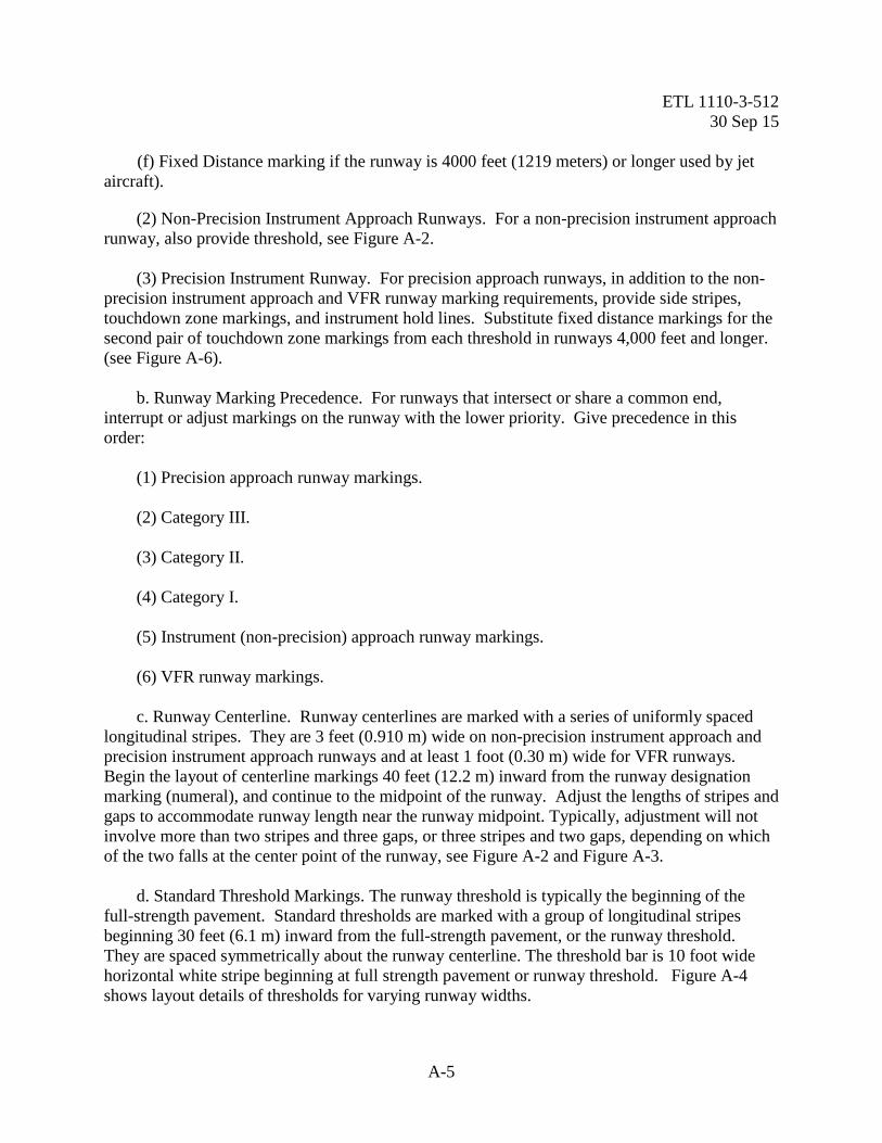
(2) Non-Precision Instrument Approach Runways. For a non-precision instrument approach runway, also provide threshold, see Figure A-2. (3) Precision Instrument Runway. For precision approach runways, in addition to the non-precision instrument approach and VFR runway marking requirements, provide side stripes, touchdown zone markings, and instrument hold lines. Substitute fixed distance markings for the second pair of touchdown zone markings from each threshold in runways 4,000 feet and longer. (see Figure A-6). b. Runway Marking Precedence. For runways that intersect or share a common end, interrupt or adjust markings on the runway with the lower priority. Give precedence in this order: (1) Precision approach runway markings. (2) Category III. (3) Category II. (4) Category I. (5) Instrument (non-precision) approach runway markings. (6) VFR runway markings. c. Runway Centerline. Runway centerlines are marked with a series of uniformly spaced longitudinal stripes. They are 3 feet (0.910 m) wide on non-precision instrument approach and precision instrument approach runways and at least 1 foot (0.30 m) wide for VFR runways. Begin the layout of centerline markings 40 feet (12.2 m) inward from the runway designation marking (numeral), and continue to the midpoint of the runway. Adjust the lengths of stripes and gaps to accommodate runway length near the runway midpoint. Typically, adjustment will not involve more than two stripes and three gaps, or three stripes and two gaps, depending on which of the two falls at the center point of the runway, see Figure A-2 and Figure A-3. d. Standard Threshold Markings. The runway threshold is typically the beginning of the full-strength pavement. Standard thresholds are marked with a group of longitudinal stripes beginning 30 feet (6.1 m) inward from the full-strength pavement, or the runway threshold. They are spaced symmetrically about the runway centerline. The threshold bar is 10 foot wide horizontal white stripe beginning at full strength pavement or runway threshold. Figure A-4 shows layout details of thresholds for varying runway widths.

ETL 1110-3-512 30 Sep 15
A-6
e. Runway Overruns. Chevron markings are used on overruns to indicate the area is not an operational surface. The index point for the layout of the chevron marking will be the point of intersection of the runway centerline and the runway threshold. The apex of the initial chevron on the approach side of the threshold will be at a point 50 feet (15.2 meters) outward from the index point. Subsequent chevrons will be placed on 100 foot (30.5 meter) centers as shown in Figure A-5. The legs of the chevrons intersect the centerline at a 45-degree angle. On runways greater than 150 feet (45.7 m) wide, the chevron legs may extend laterally beyond the runway threshold and side stripe markings; however, do not extend them beyond the runway shoulder markings (deceptive surface markings). A typical layout plan and dimensions for these markings are shown in Figure A-5. f. Touchdown Zone and Fixed Distance Markings. (1) Touchdown Zone. Markings consist of pairs of longitudinal stripes placed symmetrically about the centerline. Three stripes are provided in the first two pairs, two stripes in the next two pairs, and single stripes in the last two pairs. The lateral distance between each pair of longitudinal stripes measured at their inner edges is a constant 72 feet (21.9 m). Omit any pair of markings that fall within 1000 feet (305 m) of the runway midpoint. The layout and dimensions are shown in Figure A-6. (2) Fixed Distance Markings. Provide fixed distance markings on runways that are at least 100 feet (30.5 m) wide and at least meters 4000 feet (1219 m) long. Substitute them in place of the second pair of touchdown zone markings. Omit touchdown zone markings that fall within 1000 feet (305 m) of the runway midpoint. The layout plan and dimensions are shown in Figure A-6.

ETL 1110-3-512 30 Sep 15
A-7
Figure A-1. Runway Marking Schemes
* FIXED DISTANCE MARKINGS REQUIRED ON RUNWAYS AT MIN. 100 FT. WIDE AND MIN. 4000 FT. LONG.
ETL 1110-3-512 30 Sep 15
A-8
Figure A-2. Non-Precision Runway Markings

ETL 1110-3-512 30 Sep 15
A-9
Figure A-3. Visual Runway Markings

ETL 1110-3-512 30 Sep 15
A-10
Figure A-4. Threshold Layout For Varying Width Runways

ETL 1110-3-512 30 Sep 15
A-11
Figure A-5. Runway Overrun Markings

ETL 1110-3-512 30 Sep 15
A-12
Figure A-6. Touchdown Zone and Fixed Distance Markings
ETL 1110-3-512 30 Sep 15
A-13
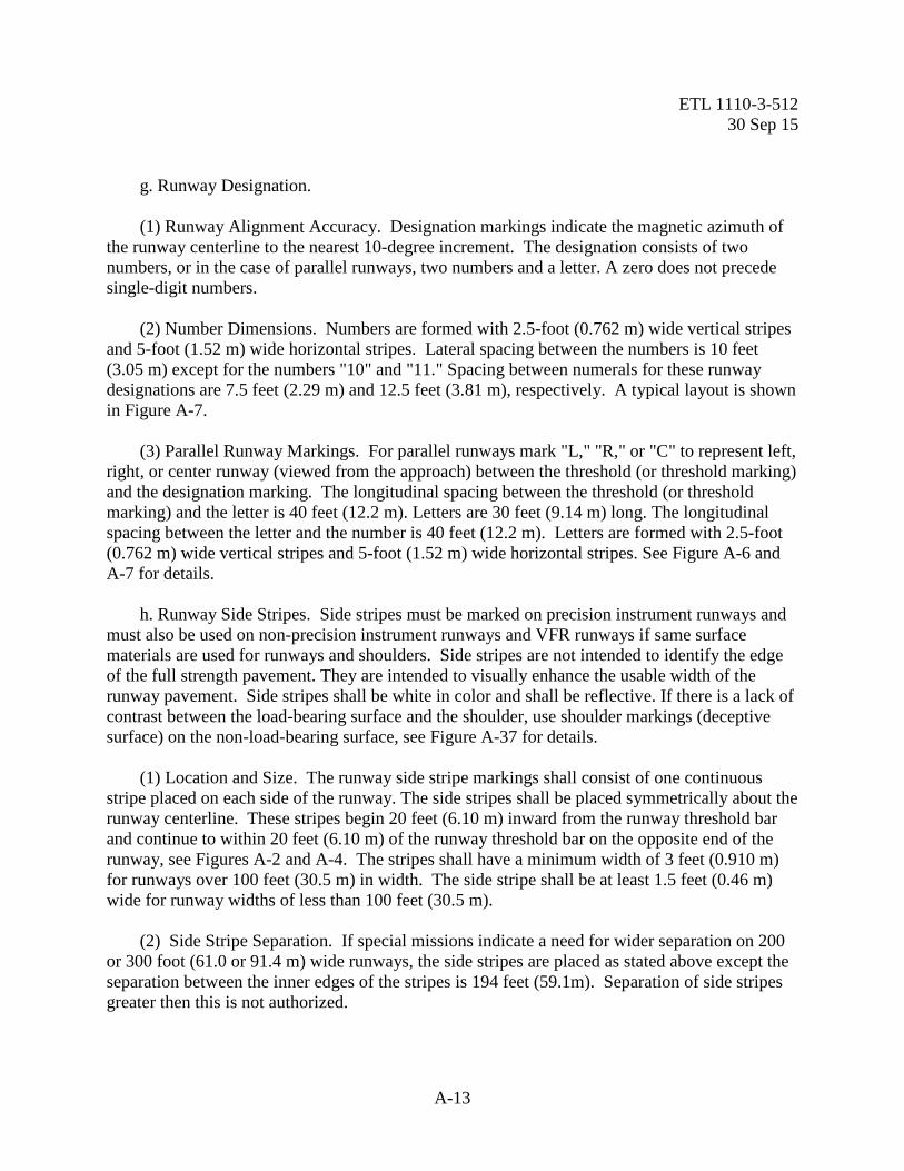
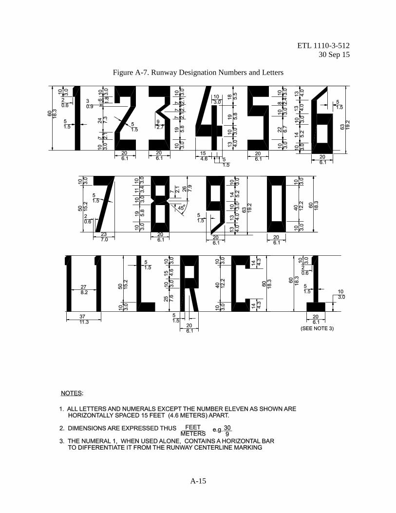
g. Runway Designation. (1) Runway Alignment Accuracy. Designation markings indicate the magnetic azimuth of the runway centerline to the nearest 10-degree increment. The designation consists of two numbers, or in the case of parallel runways, two numbers and a letter. A zero does not precede single-digit numbers. (2) Number Dimensions. Numbers are formed with 2.5-foot (0.762 m) wide vertical stripes and 5-foot (1.52 m) wide horizontal stripes. Lateral spacing between the numbers is 10 feet (3.05 m) except for the numbers "10" and "11." Spacing between numerals for these runway designations are 7.5 feet (2.29 m) and 12.5 feet (3.81 m), respectively. A typical layout is shown in Figure A-7. (3) Parallel Runway Markings. For parallel runways mark "L," "R," or "C" to represent left, right, or center runway (viewed from the approach) between the threshold (or threshold marking) and the designation marking. The longitudinal spacing between the threshold (or threshold marking) and the letter is 40 feet (12.2 m). Letters are 30 feet (9.14 m) long. The longitudinal spacing between the letter and the number is 40 feet (12.2 m). Letters are formed with 2.5-foot (0.762 m) wide vertical stripes and 5-foot (1.52 m) wide horizontal stripes. See Figure A-6 and A-7 for details. h. Runway Side Stripes. Side stripes must be marked on precision instrument runways and must also be used on non-precision instrument runways and VFR runways if same surface materials are used for runways and shoulders. Side stripes are not intended to identify the edge of the full strength pavement. They are intended to visually enhance the usable width of the runway pavement. Side stripes shall be white in color and shall be reflective. If there is a lack of contrast between the load-bearing surface and the shoulder, use shoulder markings (deceptive surface) on the non-load-bearing surface, see Figure A-37 for details. (1) Location and Size. The runway side stripe markings shall consist of one continuous stripe placed on each side of the runway. The side stripes shall be placed symmetrically about the runway centerline. These stripes begin 20 feet (6.10 m) inward from the runway threshold bar and continue to within 20 feet (6.10 m) of the runway threshold bar on the opposite end of the runway, see Figures A-2 and A-4. The stripes shall have a minimum width of 3 feet (0.910 m) for runways over 100 feet (30.5 m) in width. The side stripe shall be at least 1.5 feet (0.46 m) wide for runway widths of less than 100 feet (30.5 m). (2) Side Stripe Separation. If special missions indicate a need for wider separation on 200 or 300 foot (61.0 or 91.4 m) wide runways, the side stripes are placed as stated above except the separation between the inner edges of the stripes is 194 feet (59.1m). Separation of side stripes greater then this is not authorized.

ETL 1110-3-512 30 Sep 15
A-14
i. Displaced Threshold Marking Schemes. There are three different schemes that may be used to mark permanent runway pavement in the displaced area. Select a scheme from those shown in Figures A-8, A-9, and A-10 that will suit the intended use of the area. Mark displaced thresholds by repositioning the standard threshold marking at the new threshold. Place a transverse stripe, threshold bar on the full strength runway pavement. Place the transverse stripe or threshold bar’s outboard edge on the runway threshold. Extend the transverse stripe or threshold bar from side stripe to side stripe. Dimensions and layout details are shown in Figure A-8, A-9, and A-10. Exception: Repositioning of the standard threshold marking is not required for temporarily displaced thresholds.
ETL 1110-3-512 30 Sep 15
A-15
Figure A-7. Runway Designation Numbers and Letters

ETL 1110-3-512 30 Sep 15
A-16
Figure A-8. Displaced Threshold where Runway Surface Used for Aircraft Take-Off

ETL 1110-3-512 30 Sep 15
A-17
Figure A-9. Relocated Threshold where Runway Surface Used as a Taxiway

ETL 1110-3-512 30 Sep 15
A-18
Figure A-10. Temporarily Displaced Threshold for Construction Purposes and Taxiway, and Displaced Threshold Preceding a Runway

ETL 1110-3-512 30 Sep 15
A-19
j. Aircraft Arresting System Warning Markings. Mark aircraft arresting system locations on the runway with a series of discs placed beneath the pendant. Where touchdown zone and disc markings coincide, the touchdown zone marking is interrupted at that location for a minimum distance of 1 foot (0.305 m) from the edge of the disc marking. If the designation and disc markings coincide, shift the designation marking longitudinally to eliminate the conflict. The layout plan and dimensions for these markings are shown in Figure A-11. Do not use these markings in overruns.
Figure A-11. Aircraft Arresting System Warning Markings
ARRESTING SYSTEM WARNINGMARKING ARRANGEMENT WHENSACRIFICIAL PANELS ARE USED
PENDANT
1.52 m (5’) RADIUS SEMI-CIRCLES
SACRIFICIALPOLYETHYLENE
PANELS
RU
NW
AY
CE
NTE
RLI
NESID
ES
TRIP
E
SID
ES
TRIP
E
CE
NTE
RLI
NE
STR
IPE
2.29 m(7.5')
4.57 m(15')
3.05 m(10')
3.05 m(10')
3.05 m (10') DIAMETER DISCS
1.52 m (5')
4.57 m(15')

ETL 1110-3-512 30 Sep 15
A-20
A-3. Fixed-Wing Taxiway and Apron Markings. a. Taxiway and Taxilane Centerline Stripe. Mark the centerline of all taxiways, guidelines on runways, and taxilanes on aprons and pads with a single continuous 6-inch (150 mm) wide yellow stripe. All directional changes are accomplished with smooth curves. Nose wheel guidelines should be positioned to maintain a clearance of at least 10 feet (3.05 m) between the aircraft's outermost main gear and the edge of the full-strength pavement when the cockpit is maintained over the nose wheel guideline through the turn. Also ensure adequate wingtip clearance is provided for the most demanding aircraft that will use the taxi route. Typical taxiway and other nose wheel guidelines are shown in Figure A-12. On runways, the curve is tangent to a line parallel to and 3 feet (0.910 m) from the near side of the runway centerline marking, and extends 200 feet (61.0 m) beyond the point of tangency. (1) Center Stripe Locations. Compute the distance from the adjacent taxiway or taxilane to provide the minimum wingtip clearance required by UFC 3-260-01, Airfield and Heliport Planning and Design, Table 6.1. Aircraft turning diagrams can be found in Technical Report TSC 13-2 Aircraft Characteristics for Military Aircraft. When marking an apron for a specific aircraft, coordinate with the airfield management and flight safety functions to ensure procedures are followed by airfield operation personnel to ensure aircraft marshallers are used for other more demanding aircraft that may use the apron. Do not paint a taxiway/taxilane stripe directly on a PCC joint. Move centerline joint left or right 9 to 12 inches of PCC joint. (2) Stop Blocks. Stop blocks may be painted at aircraft parking positions to indicate the intended location for the aircraft nose wheel when parked. Stop blocks are painted reflective yellow and are 1.5 feet (0.460 m) long and 1.5 feet (0.460 m) wide, centered on the taxiway centerline. See Figure A-44. (3) Center Stripe Turning Radius. On hammerheads, aprons, and pads, and at runway/taxiway and taxiway/taxiway intersections, the radius for the curve must be greater than the minimum turning radius for the assigned mission aircraft, and should be positioned to maintain a clearance of at least 10 feet (3.05 m) between the outermost main gear of a C-5 and the edge of the full-strength pavement. See Technical Report TSC 13-2 Aircraft Characteristic for Military Aircraft for aircraft turning diagrams. The recommended radius for 90-degree runway/taxiway intersections is 150 feet (45.7 m). The recommended radius for 90-degree taxiway/taxiway intersections is 125 feet (38.1 m). Other radii can be used for these as well as other intersections, depending on local requirements. In all cases, ensure these radii will accommodate the pavement structure (clearance between outer main gear and edge of pavement) for the most demanding aircraft that will use the intersection before marking nose-wheel guidelines at these dimensions. b. Holding Positions. Holding positions are necessary on all pavements that lead to an active runway or helipad. They designate a boundary intended to protect the runway or helipad environment from incursions and prevent interference with signals transmitted by electronic navigational aids. There are three patterns for marking hold positions: one is used to mark hold

ETL 1110-3-512 30 Sep 15
A-21
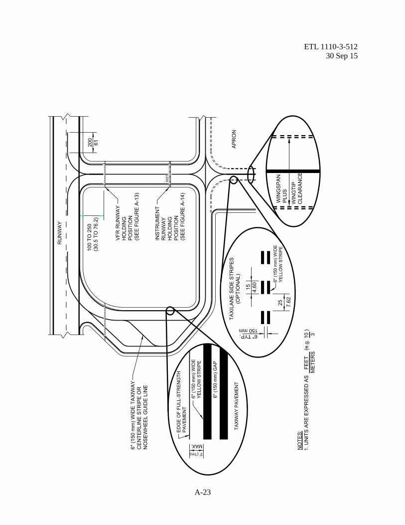
positions used for VFR conditions, the second is used as an option for enhanced runway hold position marking, and the third is used to mark instrument (“INST”) hold positions. Figure A-13 show how to mark a VFR hold line, Figure A-14 shows marking of enhanced hold position marking, and Figure A-15 shows the layout for an instrument hold line. Both the VFR and instrument holding positions are marked from edge to edge of the pavement surface, including paved shoulders. (1) Enhanced Markings For Runway Holding Position. Enhanced markings are intended to be a visual precursor to an approaching runway holding position. These markings are intended to prevent runway incursion and therefore are an option for any fixed wing facility. The location and dimension of hold position marking shall be set per paragraph “VFR Runway Holding Position” below. See Figure A-14 for details. For additional guidance on marking pavements and at joint use facilities mark in accordance with FAA AC 150/5340. (2) VFR Runway Holding Position. This holding position is located 100 to 250 feet (30.5 to 76.2 m) from the near edge of the runway. The minimum setback from the runway edge is 100 feet (30.5 m). This distance is measured perpendicular to the long axis of the runway. Calculate distances from the runway centerline by dividing the published runway width by 2 and adding the required clearance distance. Where practical, setback distances for the VFR runway holding position should be increased for instrument runways and where the wingspan of the controlling aircraft is greater than 79 feet (24.1 m). Suggested increased setback distances from the runway edge are: 175 feet (53.3 m) for controlling aircraft with wingspans from 79 to 171 feet (24.1 to 52.1 m); and 205 feet (62.5 m) for controlling aircraft with wingspans greater than 171 feet (52.1 m). Increase these distances by 1 foot (0.305 m) for each 100 feet (30.5 m) of airfield elevation above sea level. The hold position may be placed parallel to the runway centerline on taxiways that enter at an angle to the runway. Note: Specific setback distances for VFR hold positions based on aircraft wingspan at many airfields will not meet the above distances. Additionally, because many airfields were constructed under previous standards, strict application of these increased setback distances may not be possible or operationally practical at every installation. The information provided above should not be viewed as a basis for an immediate or mandatory change in the location of VFR holding positions at any given base. Furthermore, if VFR holding positions are relocated, obliteration by painting over the old marking is not acceptable; they must be completely removed. Changes in the locations of VFR holding positions should be implemented during a normal remarking cycle to minimize costs.

ETL 1110-3-512 30 Sep 15
A-22
Figure A-12. Taxiway Markings
ETL 1110-3-512 30 Sep 15
A-23

ETL 1110-3-512 30 Sep 15
A-24
Figure A-13. VFR Runway Holding Position Markings

ETL 1110-3-512 30 Sep 15
A-25
Figure A-14. Enhanced Taxiway Centerline Markings(optional)

ETL 1110-3-512 30 Sep 15
A-26
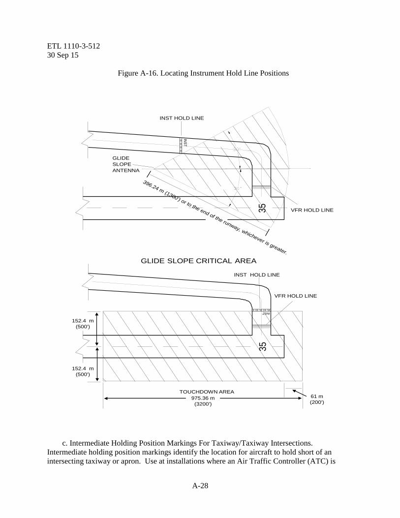
(3) Instrument Holding Position. Runways served by precision instrument navigation aids may require an instrument holding position be marked in addition to the VFR holding position. Where practical, collocate these markings and mark only the VFR holding position. Locate the instrument holding position further from the active runway to prevent taxiing or holding aircraft from interfering with signals transmitted to inbound aircraft during Instrument Meteorological Conditions (IMC) and to protect aircraft and vehicles in the Precision Obstacle Free Zone (POFZ). The ILS critical area/POFZ holding position marking identifies the location on a taxiway or holding bay where an aircraft is to stop when it does not have clearance to enter the ILS critical area or the POFZ. This marking also can be used to identify the holding position for CAT II/III operations. Marking the boundary of these areas is necessary to protect the navigational aid signal. The markings are installed perpendicular to the taxiway centerline but may be canted from the perpendicular in unique situations. If a taxiway penetrates the POFZ, only one holding position marking should be installed to delineate the ILS critical area and the POFZ. This holding position marking should be located at the more conservative boundary of these two areas. In this instance, the ILS/POFZ holding position marking cannot be replaced with, or used in lieu of, a runway holding position marking. The airfield manager will designate the ILS (or MLS) critical area and POFZ boundaries and, as appropriate, determine the holding position location for CAT II/III operations for the airport operator. (a) Instrument Hold Line Position Characteristics. The hold position is configured differently from a VFR hold position and is augmented with the letters "INST" on the runway side of the line. The letters are to be read when facing the runway. They are marked in block letters 6 feet (1.83 m) high by 2 feet (0.610 m) wide, spaced 1 foot (0.305 m) apart. The letters are formed with a 6-inch (150 mm) stroke. The "INST" designator must be placed symmetrically between the taxiway centerline and the taxiway edge or edge marking on the left side of the centerline. For hold lines over 200 feet (61.0 m) long, mark the "INST" designator at intervals not exceeding 150 feet (45.7 m). Locations for the instrument hold line vary, depending on the type and capability of the landing aid; locate them in accordance with the following paragraphs. (b) Instrument Holding Position (Runway Served by Instrument Landing System (ILS)/Precision Obstacle Free Zone (POFZ). If the height above touchdown (HAT) is 250 feet (76.2 m) or greater (ask the airfield manager), mark the instrument holding position at the edge of the glide slope critical area. If the HAT is less than 250 feet (76.2 m), mark the holding position at the edge of the touchdown area or the glide slope critical area, whichever is farther from the edge of the runway. The glide slope critical area and touchdown area are shown in Figure A-15. The instrument hold line must be at least 500 feet (152 m) from the runway centerline when the touchdown area criteria apply. (c) Instrument Holding Position (Runway Served by Precision Approach Radar (PAR))/Precision Obstacle Free Zone (POFZ). Establish the instrument hold line at the edge of the touchdown area (Figure A-15) if the PAR serving that runway has a HAT less than 200 feet (61.0 m). If the HAT is 250 feet (76.2 m) or greater, no instrument hold position is needed.

ETL 1110-3-512 30 Sep 15
A-27
(d) VFR Hold Position. In all cases ensure a VFR hold position is marked between all instrument hold positions and the active runway. However, if either of the following examples applies, mark a VFR hold line only if: The runway hold line and the instrument hold line happen to fall at the same location, or The additional taxi time required to move from the instrument hold position to the runway is operationally acceptable under VFR.
Figure A-15. Instrument Holding Position Markings
ETL 1110-3-512 30 Sep 15
A-28
Figure A-16. Locating Instrument Hold Line Positions
c. Intermediate Holding Position Markings For Taxiway/Taxiway Intersections. Intermediate holding position markings identify the location for aircraft to hold short of an intersecting taxiway or apron. Use at installations where an Air Traffic Controller (ATC) is
3535
GLIDE SLOPE CRITICAL AREA
INST HOLD LINE
975.36 m(3200')
61 m(200')
VFR HOLD LINE
GLIDESLOPEANTENNA
INST HOLD LINE
396.24 m (1300') or to the end of the runway, whichever is greater.
152.4 m(500')
TOUCHDOWN AREA
INST
INST
VFR HOLD LINE
152.4 m(500')
ETL 1110-3-512 30 Sep 15
A-29
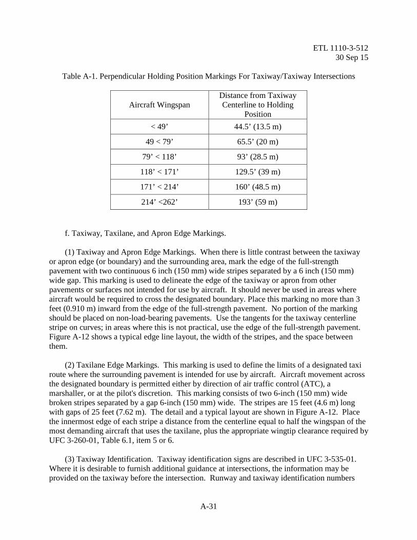
operational. These markings are permissible where there is an operational need for aircraft to hold short of taxiway or apron intersections. Intermediate holding position markings are reflective yellow and are located perpendicular to the taxiway centerline as shown in Table A-1 and Figure A-17. d. Non-movement area boundary markings are used to delineate the movement area (under Air Traffic Control (ATC), from the non-movement area, (No ATC approval required). The non-movement area boundary marking consists of two yellow lines (one solid and one dashed) as shown in Figure 10. The solid line is located on the non-movement area side while the dashed yellow line is located on the movement area side. Each line is 6 inches (15 cm) in width with a 6 inch spacing between lines. If a taxiway centerline intersects a non-movement area boundary marking, the boundary marking shall be 6 inches from the taxiway centerline on the aircraft holding side and 3 feet (0.9 m) from the taxiway centerline on the movement area side. See Fig: A-36. e. Where needed an obstruction clearance line can be used to delineate an apron lateral clearance area defined in UFC 3-260-01. The line is used to prevent fixed and mobile (maintenance vehicles, equipment and storage bins, etc.) from encroaching into the required apron lateral clearance. The obstruction clearance line consists of a single solid line 4 inches wide. The line is non-reflective and the color is green. The obstruction clearance line cannot be painted within the usable portion of the apron. However, may be painted at/near hangars entrances/exits. See Figure A-44 for detail of obstruction clearance line.

ETL 1110-3-512 30 Sep 15
A-30
Figure A-17. Intermediate Holding Position Markings For Taxiway/Taxiway Intersections
ETL 1110-3-512 30 Sep 15
A-31
Table A-1. Perpendicular Holding Position Markings For Taxiway/Taxiway Intersections
Aircraft Wingspan Distance from Taxiway Centerline to Holding
Position < 49’ 44.5’ (13.5 m)
49 < 79’ 65.5’ (20 m)
79’ < 118’ 93’ (28.5 m)
118’ < 171’ 129.5’ (39 m)
171’ < 214’ 160’ (48.5 m)
214’ <262’ 193’ (59 m) f. Taxiway, Taxilane, and Apron Edge Markings. (1) Taxiway and Apron Edge Markings. When there is little contrast between the taxiway or apron edge (or boundary) and the surrounding area, mark the edge of the full-strength pavement with two continuous 6 inch (150 mm) wide stripes separated by a 6 inch (150 mm) wide gap. This marking is used to delineate the edge of the taxiway or apron from other pavements or surfaces not intended for use by aircraft. It should never be used in areas where aircraft would be required to cross the designated boundary. Place this marking no more than 3 feet (0.910 m) inward from the edge of the full-strength pavement. No portion of the marking should be placed on non-load-bearing pavements. Use the tangents for the taxiway centerline stripe on curves; in areas where this is not practical, use the edge of the full-strength pavement. Figure A-12 shows a typical edge line layout, the width of the stripes, and the space between them. (2) Taxilane Edge Markings. This marking is used to define the limits of a designated taxi route where the surrounding pavement is intended for use by aircraft. Aircraft movement across the designated boundary is permitted either by direction of air traffic control (ATC), a marshaller, or at the pilot's discretion. This marking consists of two 6-inch (150 mm) wide broken stripes separated by a gap 6-inch (150 mm) wide. The stripes are 15 feet (4.6 m) long with gaps of 25 feet (7.62 m). The detail and a typical layout are shown in Figure A-12. Place the innermost edge of each stripe a distance from the centerline equal to half the wingspan of the most demanding aircraft that uses the taxilane, plus the appropriate wingtip clearance required by UFC 3-260-01, Table 6.1, item 5 or 6. (3) Taxiway Identification. Taxiway identification signs are described in UFC 3-535-01. Where it is desirable to furnish additional guidance at intersections, the information may be provided on the taxiway before the intersection. Runway and taxiway identification numbers
ETL 1110-3-512 30 Sep 15
A-32
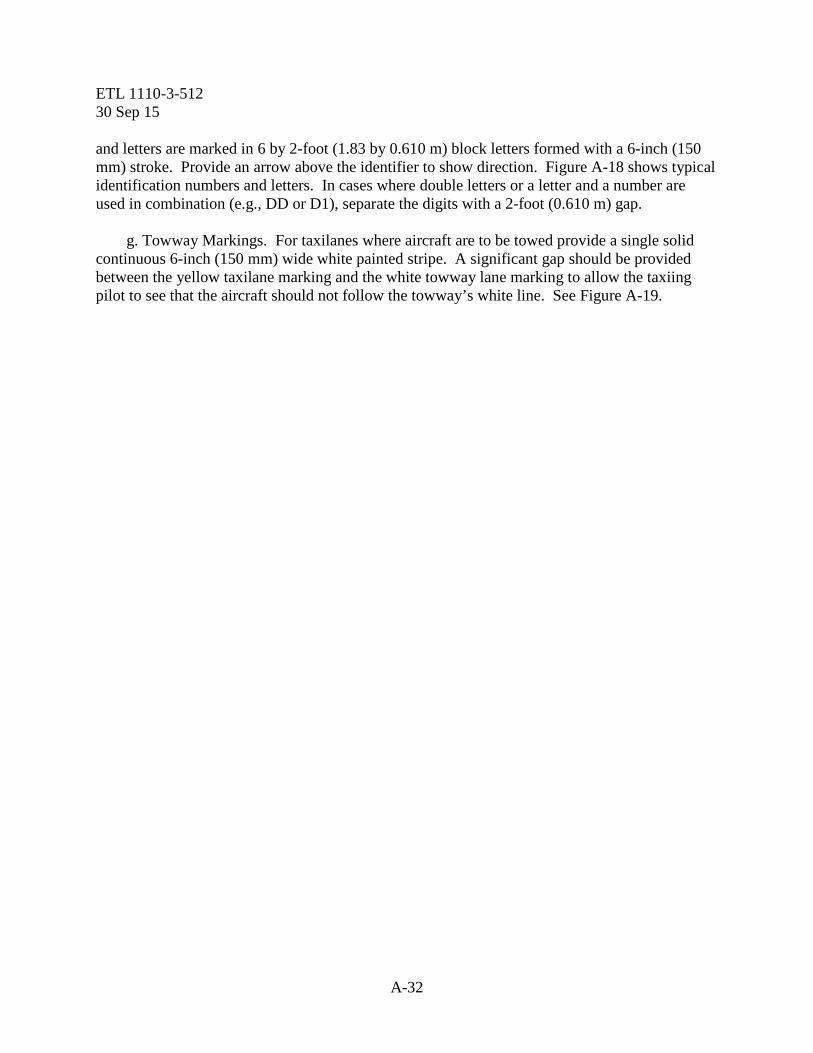
and letters are marked in 6 by 2-foot (1.83 by 0.610 m) block letters formed with a 6-inch (150 mm) stroke. Provide an arrow above the identifier to show direction. Figure A-18 shows typical identification numbers and letters. In cases where double letters or a letter and a number are used in combination (e.g., DD or D1), separate the digits with a 2-foot (0.610 m) gap. g. Towway Markings. For taxilanes where aircraft are to be towed provide a single solid continuous 6-inch (150 mm) wide white painted stripe. A significant gap should be provided between the yellow taxilane marking and the white towway lane marking to allow the taxiing pilot to see that the aircraft should not follow the towway’s white line. See Figure A-19.

ETL 1110-3-512 30 Sep 15
A-33
Figure A-18. Taxiway and Runway Identification
IDENTIFICATION WILL BE 1829 mm (6')HIGH BLOCK LETTERS AND/OR NUMBERSUSING A 152mm (6") STROKE.
EDGE MARKINGIF REQUIRED
PAVED SHOULDER
RUNWAY CENTERLINE
25 07
D D
TAXIWAY "D"
AA
D
D
TO APRONTO RUNWAY END 25
TAXIWAY CENTERLINE STRIPE
TAXIWAY “A”
1829 mm(6’)
610 mm(2’)
61 m (200')
1 m(3')
600 mm(2')
600 mm(2')
45°
600 mm(2')
460 mm(1.5')
071200 mm
(4')
Taxiway Centerline
914 mm(3')
15 m(50')
D152 mm
(6')
RUNWAY EDGE
PAVED SHOULDER

ETL 1110-3-512 30 Sep 15
A-34
Figure A-19. Towway Centerline Marking
A-4. Rotary wing runways, taxiways, aprons, helipads and other pavements at rotary wing facilities. General. Marking rotary wing facilities will conform to the requirements as set forth below and govern the initial marking and re-marking of serviceable runways, taxiways, landing pads, and other areas designated for rotary wing operations. a. Marking With Paint. Initial marking of runways and taxiways should be done as soon as possible, subsequent to the required curing period. Re-marking or revising existing markings should be accomplished as often as necessary. The effectiveness of markings is heavily dependent upon their proper maintenance to provide maximum contrast with backgrounds.

ETL 1110-3-512 30 Sep 15
A-35
(1) Color Marking. All runways will be marked with white reflective paint. Identification markers, landing pads and hoverpoints will be marked with white non-reflective paint. All taxiways will be painted with yellow reflective paint. (2) Application of Paint. Painted marking will be applied to paved areas only after the pavements have been allowed to cure thoroughly. New pavement surfaces will be allowed to cure for a minimum of 30 days before application of marking materials. Care will be taken to insure that the pavement surface is dry and clean prior to painting. See Paragraph A-1 for paint application rates. (3) Rigid Pavements. When painted markings are to be applied to rigid pavements that have been cured with a membrane-type curing compound, the surface to be painted must be cleaned thoroughly and the curing compound must be removed by sandblasting, or high pressure water blasting. Attention shall be given to excessive blasting of the concrete surface when using high water pressure methods. Removal methods shall only be sufficient to remove curing compound, old paint or laitance. Do not expose the coarse aggregate in the concrete. (4) Flexible Pavements. Flexible pavements will be allowed to cure as long as practical before painting, and to prevent undue softening of the bitumen by the paint. The minimum drying-time requirements of the paint specifications will be strictly enforced. b. Increasing Visibility of Markings. Marking with black borders are intended to increase the visibility of markings at heliports. The contrast of a marking on concrete pavement surfaces and light colored pavements can be increased by outlining all edges of the marking with a black border that is 6 inches (150 mm) in width. See Paragraph A-1 for details. c. Runway Markings. Retroreflective markings on rotary wing facilities will consist of centerline marking and runway designation numbers, and a helipad “H” letter without the border as shown in Figure A-27. The helipad “H” letter shall be centered below the designation number. (1) Runway Centerline Markings. The runway centerline marking will be a solid and continuous retroreflective white line, 1-foot (0.30 m) in width. The centerline stripe of each runway will terminate 20 feet (6.10 m) from the runway-designation number as shown in Figure A-21. (2) Runway Edge Marking. The edge of the full-strength pavement may be marked with a solid and continuous retroreflective white 1-foot (0.305 m) wide line. For light colored pavements a 6 inch (150 mm) wide black border may be used. This marking is used to delineate the edge of the runway from other pavements or surfaces not intended for use by aircraft. It should never be used in areas where aircraft would be required to cross the designated boundary. Place this marking no more than 3 feet (0.910 m) inward from the edge of the full-strength pavement. No portion of the marking should be placed on non-load-bearing pavements.

ETL 1110-3-512 30 Sep 15
A-36
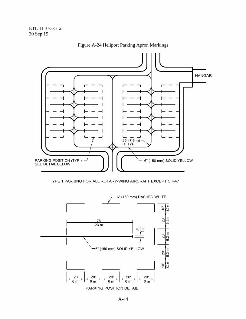
(3) Runway Designation Number. Each runway end will be designated by number and, where required, by letter. Numbers and letters assigned will be determined from the approach direction and will conform to the form and dimensions shown in Figure A-21. The number assigned will be the whole number nearest one tenth of the magnetic azimuth of the centerline of the runway, measured clockwise from the magnetic North. Single digits will not be preceded by a zero. Where required, the letters used to differentiate between parallel runways will be as follows in the order shown from left to right, for two or three parallel runways; "L", “C”, "R". The “H” designation marking pattern will be 15’ below the runway designation number and in accordance with dimensional criteria in figure A-21. (4) Intersection of Runway Ends. Where runway ends have a common intersection, preference in location of the marking will be given to the more important runway. d. Taxiway Markings. (1) Centerline Marking. Marking on serviceable taxiways will consist of a centerline stripe and a holding line. The centerline stripe will be a solid reflective yellow line 6 inches (150 mm) in width. Where a taxiway and a runway have a common intersection, the centerline marking of the taxiway will terminate at a point in line with the inside edge of the runway as shown in Figure A-20. (2) Hold-Line Marking. Provide hold position markings at appropriate locations to protect against incursions. The hold-line marking for VFR conditions will be as shown in Detail "A" of Figure A-20 and will be located 100 feet (30.5 m) from the inside edge of the adjacent runway. Apply an instrument hold marking when required to protect the instrument critical areas. See Paragraph A-3 to determine if an instrument hold position will be needed. If any taxiways enter the helipad in the normal direction of approach or departure, place a holding position marking outside the clear zone as determined in UFC 3-260-01. e. Aprons. Apron taxi centerlines will be a solid yellow line 6 inches (150 mm) in width. Parking positions will be marked with a dashed white line 6 inches (150 mm) in width. See Figures A-23, A-24, A-25 and A-26 for layout. f. Helipads. (1) Helipad Perimeter and Identification Markings. Mark a perimeter boundary with a capital "H" in the center to identify a pad intended for helicopter operations. Orient the “H” so it is aligned with the normal direction of approach (appears as an “H” to pilots during their approach to landing). If the facility is intended for single-direction ingress and egress, mark a bar beneath the “H” to show the intended direction of approach/departure. The length of the bar should be at least equal to the overall width of the “H” and the width equal to Dimension “C” in Figure A-27. Provide a space between the “H” and the bar equal to half of the bar width. The perimeter boundary marking consists of a broken square marked at the corners and along the edges to delineate the limits of the safe touchdown area. The boundary must be sized to

ETL 1110-3-512 30 Sep 15
A-37
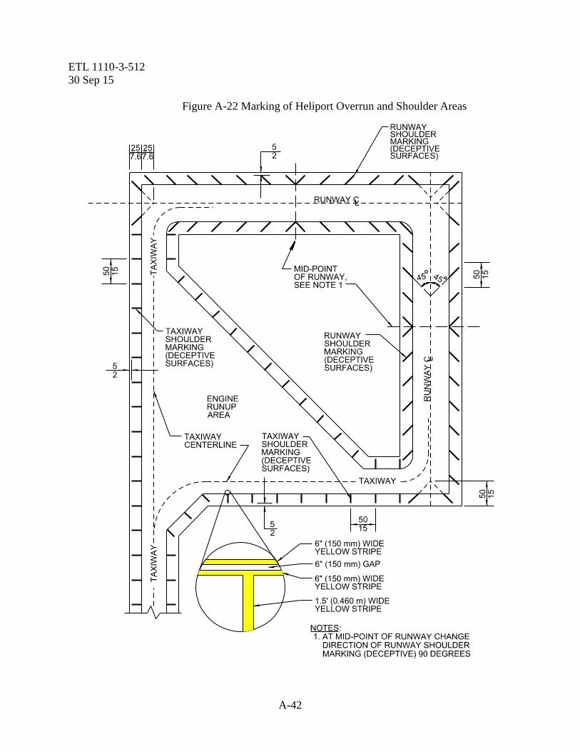
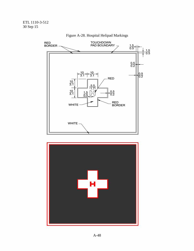
accommodate the overall length of the largest helicopter using the facility. Figure A-27 provides dimensions and layout details. (2) Hospital Helipad Markings. Medical facility helipads are marked similarly to standard helipads with the following exceptions: the perimeter border may be formed of a solid line and bordered in red, and the letter "H" is marked in red and superimposed on a white cross. Figure A-28 shows the dimensions and colors for this marking scheme. Cross and pad boundary markings are white and may be outlined with a 6-inch (150 mm) wide red border to improve contrast. Pad boundary markings may be either a solid or segmented line as shown in Figure A-28. (a) Application. The marking pattern will be used as an identification marker at all heliports at ground level, elevated, and at helicopter takeoff and landing areas at any other location. All helicopter landing areas bearing the outdated day marker or nonstandard identification marking will be re-marked with the proper identification marking as soon as practical. (b) Location. The marker will be placed in the approximate center of the touchdown area of all helicopter landing pads and at the ends of all helicopter runways. (3) Elevated Helipad Markings. The markings shall be as shown in figuresA-27, A-28, and A-29 with addition of information box with max takeoff weight and max rotor diameter included in direction of egress into helipad. (4) Landing Lanes. The marking shall be as shown in Figure A-32. The landing lanes shall provide for simultaneous operation of a number of helicopters at one time. The marking shown can provide multiple touchdown areas on a landing lane. g. Overruns and Shoulder Markings. (1) General. Overrun and shoulder areas that are not intended for aircraft traffic will be identified with deceptive surface markings. These markings shall be lines 1.5 foot (0.460 m) wide in accordance with the requirements below. Configurations complying with these requirements are detailed in Figure A-22. (a) Color. All heliport overrun and shoulder areas will be marked with non-reflective yellow paint. (b) Materials. Non-reflective paint used in marking or re-marking overruns and shoulder areas will consist of the pigmented binder (paint) stated in Paragraph A-1. (c) Application of Paint. Painted markings will be applied to overrun and shoulder areas only after the flexible pavement has been allowed to cure as long as practical. All rigid pavement shall be cleaned of all laitance prior to marking. Care will be taken to insure that the surface to be painted is clean and dry prior to painting. To prevent undue softening of the
ETL 1110-3-512 30 Sep 15
A-38
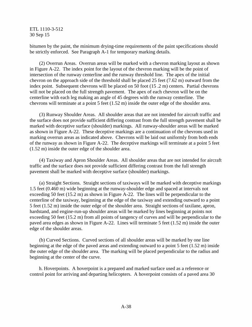
bitumen by the paint, the minimum drying-time requirements of the paint specifications should be strictly enforced. See Paragraph A-1 for temporary marking details. (2) Overrun Areas. Overrun areas will be marked with a chevron marking layout as shown in Figure A-22. The index point for the layout of the chevron marking will be the point of intersection of the runway centerline and the runway threshold line. The apex of the initial chevron on the approach side of the threshold shall be placed 25 feet (7.62 m) outward from the index point. Subsequent chevrons will be placed on 50 foot (15 .2 m) centers. Partial chevrons will not be placed on the full strength pavement. The apex of each chevron will be on the centerline with each leg making an angle of 45 degrees with the runway centerline. The chevrons will terminate at a point 5 feet (1.52 m) inside the outer edge of the shoulder area. (3) Runway Shoulder Areas. All shoulder areas that are not intended for aircraft traffic and the surface does not provide sufficient differing contrast from the full strength pavement shall be marked with deceptive surface (shoulder) markings. All runway-shoulder areas will be marked as shown in Figure A-22. These deceptive markings are a continuation of the chevrons used in marking overrun areas as indicated above. Chevrons will be laid out uniformly from both ends of the runway as shown in Figure A-22. The deceptive markings will terminate at a point 5 feet (1.52 m) inside the outer edge of the shoulder area. (4) Taxiway and Apron Shoulder Areas. All shoulder areas that are not intended for aircraft traffic and the surface does not provide sufficient differing contrast from the full strength pavement shall be marked with deceptive surface (shoulder) markings. (a) Straight Sections. Straight sections of taxiways will be marked with deceptive markings 1.5 feet (0.460 m) wide beginning at the runway-shoulder edge and spaced at intervals not exceeding 50 feet (15.2 m) as shown in Figure A-22. The lines will be perpendicular to the centerline of the taxiway, beginning at the edge of the taxiway and extending outward to a point 5 feet (1.52 m) inside the outer edge of the shoulder area. Straight sections of taxilane, apron, hardstand, and engine-run-up shoulder areas will be marked by lines beginning at points not exceeding 50 feet (15.2 m) from all points of tangency of curves and will be perpendicular to the paved area edges as shown in Figure A-22. Lines will terminate 5 feet (1.52 m) inside the outer edge of the shoulder areas. (b) Curved Sections. Curved sections of all shoulder areas will be marked by one line beginning at the edge of the paved areas and extending outward to a point 5 feet (1.52 m) inside the outer edge of the shoulder area. The marking will be placed perpendicular to the radius and beginning at the center of the curve. h. Hoverpoints. A hoverpoint is a prepared and marked surface used as a reference or control point for arriving and departing helicopters. A hoverpoint consists of a paved area 30
ETL 1110-3-512 30 Sep 15
A-39
feet in diameter domed to a 6-inch height in the center. If a hover point is installed on existing pavement (taxiway) the 6-inch dome need not be constructed. The dome will be marked white. When located on a taxiway, the marking will be centered on the taxiway centerline. See Figure A-31.

ETL 1110-3-512 30 Sep 15
A-40
Figure A-20. Heliport Runway and Taxiway Markings

ETL 1110-3-512 30 Sep 15
A-41
Figure A-21. Rotary Wing Numeral and Letter Markings
ETL 1110-3-512 30 Sep 15
A-42
Figure A-22 Marking of Heliport Overrun and Shoulder Areas

ETL 1110-3-512 30 Sep 15
A-43
Figure A-23 Heliport Parking Apron Markings
ETL 1110-3-512 30 Sep 15
A-44
Figure A-24 Heliport Parking Apron Markings

ETL 1110-3-512 30 Sep 15
A-45
Figure A-25 Heliport Parking Apron Markings

ETL 1110-3-512 30 Sep 15
A-46
Figure A-26 Heliport Parking Apron Markings

ETL 1110-3-512 30 Sep 15
A-47
Figure A-27. Helipad Perimeter and Identification Markings
ETL 1110-3-512 30 Sep 15
A-48
Figure A-28. Hospital Helipad Markings

ETL 1110-3-512 30 Sep 15
A-49
Figure A-29. Elevated Helipad Markings

ETL 1110-3-512 30 Sep 15
A-50

ETL 1110-3-512 30 Sep 15
A-51
Figure A-30. Marking of Shoulders for Heliport Parking, Maintenance Areas, and Taxiways

ETL 1110-3-512 30 Sep 15
A-52
Figure A-31 Hoverpoints
A-5. Other Pavement Markings.
a. Closed Pavement Markings. Closed runways must also be marked to reflect their non-operational status. Markings must be visible to aircrew for all missions. Runways should be marked in a manner that will allow the aircrew to successfully locate, identify, and respond to hazards according to the mission type being flown (i.e., night IMC or night vision goggle (NVG) operations). Reflectivity and marker angles must be anticipated from an airborne perspective. Pavements that are hazardous to aircraft traffic are marked with large “X”s. Refer to Figure A-33 and Figure A-34 for the dimensions and layout details. The following paragraphs describe the placement of these markings and alternatives for temporarily closed areas. (1) Permanently Closed Runways. Obliterate the designation numbers on both ends of the runway and mark an "X" in place of the numbers. An "X" is also placed on the runway centerline at evenly spaced intervals not exceeding 1000 feet (305 m). Where operational pavements cross a closed runway, place an "X" on the closed runway adjacent to both edges of the serviceable pavement and obliterate any runway markings which conflict with the serviceable pavement. Figure A-34 shows the typical placement of these markings. (2) Permanently Closed Taxiways. Obliterate the centerline stripe and mark the taxiway with an "X" marking that is placed at each entrance of closed taxiway, and along the taxiway centerline at evenly spaced intervals not exceeding 1000 feet (305 m). Refer to Figure A-34 for the dimensions and layout details and Figure A-33 for typical placement. Additionally, obliterate all extraneous taxiway markings from the adjacent serviceable pavements. For example, remove or hide any line delineating a route from an active runway to a closed taxiway.

ETL 1110-3-512 30 Sep 15
A-53
(4) Temporarily Closed Runways. When temporarily closing a runway, the "X" may be fabricated of plywood, canvas, painted picket fence sections, preformed marking tape, or other materials, such as yellow snow fencing. These can be anchored by any suitable means, such as with nails or sandbags. Another alternative is using lighted "X”s as described in FAA AC 150/5340-1, Standards for Airport Markings, and FAA AC 150/5345-55, Lighted Visual Aid to Indicate Temporary Runway Closure. Place an "X" at both ends of the runway on top of the runway designation number. For temporary purposes, the dimensions of the "X" shown in Figure A-33 may be reduced to allow use of standard 4 by 8-foot (1.22 by 2.44 m) sheets of plywood. Note: Runways closed for periods of five days or less do not need to be marked if a Notice to Airmen (NOTAM) is issued to publicize the closure. (5) Temporarily Closed Taxiways, Aprons, and Taxilanes. Use materials described in paragraph A-5.a(3) to construct and fasten markers to the pavement. Ensure an "X" is placed at all access points to the closed pavement. In this case, it is not necessary to obliterate the existing markings, but if the area will be used during periods of reduced visibility or darkness, use lighted barricades to ensure the area is adequately marked. If lighted barricades are used to block the access point to the closed pavement, the "X" may be omitted. See paragraph A-5.b and Figure A-34. (6) Closed Aprons. When an apron is closed on an active airfield, taxilanes and taxiways leading to the closed area are marked as closed. If the closed apron area adjoins an active apron, supplemental markings are needed to indicate the division between the two areas. The separation is marked with two continuous apron edge stripes as described in Paragraph A-3, paragraph, “Taxiway, Taxilane, and Apron Edge Side Stripes”, and shown in Figure A-12. The letter "X," as described above, is marked 3 feet (0.910 m) inward toward the closed apron at intervals not exceeding 200 feet (61.0 m) on the closed apron sides. Figure A-34 shows the dimensions and typical layout for these markings.

ETL 1110-3-512 30 Sep 15
A-54
Figure A-32. Marking of Landing Lane

ETL 1110-3-512 30 Sep 15
A-55
Figure A-33. Closed Pavement Markings Dimensions

ETL 1110-3-512 30 Sep 15
A-56
Figure A-34. Placement of Closed Pavement Markings
CLOSED APRONS900 mm
(3')
305 m (1000') MAXIMUM
CLOSED TAXIWAYS
CLOSED RUNWAY
305 m (1000')MAXIMUM
15.2 m (50')
34
203 mm(8")
90o
1.2 m (4')
900 mm (3')
61 m (200')MAXIMUMAPRON
EDGESTRIPES

ETL 1110-3-512 30 Sep 15
A-57
b. Barricades. Where pavement markings do not provide adequate definitions of closed or hazardous areas use reflective orange and white barricades or traffic cones with securely fastened red lights. All barricades and traffic cones must be anchored or heavy enough to remain in place. Flashing lights must be at least five candelas effective intensity and flash at a rate of from 55 to 160 flashes per minute. Continuous burning lights must have an effective intensity of 10 candelas. Low-profile barricades are the preferred method for marking construction areas. Examples are shown in Figure A-35. Lighted barricades used in close proximity should all be the same type (flash rate) and color. Place barricades at maximum intervals of 10 feet (3 m) and use dual barricades and lights on corners and ends.
Figure A-35. Barricades
ETL 1110-3-512 30 Sep 15
A-58
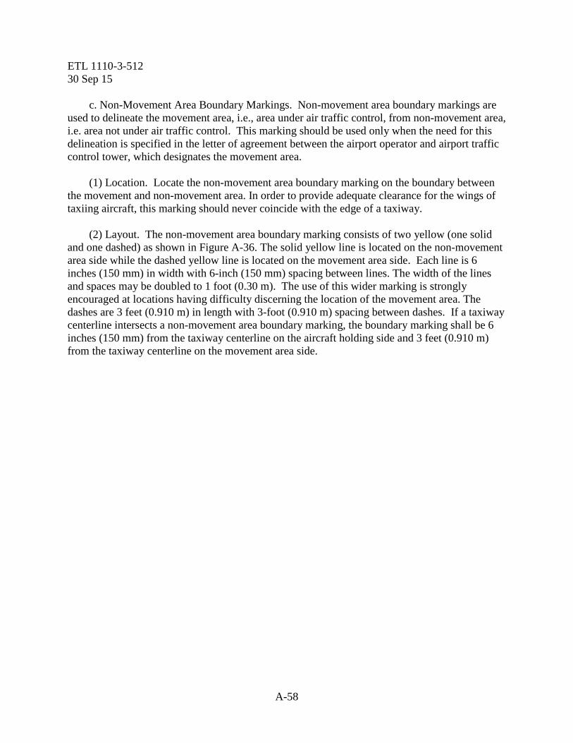
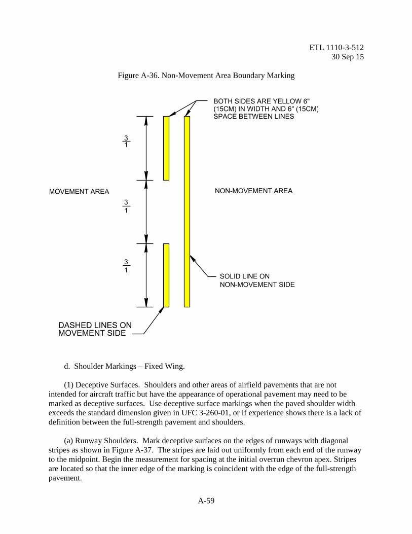
c. Non-Movement Area Boundary Markings. Non-movement area boundary markings are used to delineate the movement area, i.e., area under air traffic control, from non-movement area, i.e. area not under air traffic control. This marking should be used only when the need for this delineation is specified in the letter of agreement between the airport operator and airport traffic control tower, which designates the movement area. (1) Location. Locate the non-movement area boundary marking on the boundary between the movement and non-movement area. In order to provide adequate clearance for the wings of taxiing aircraft, this marking should never coincide with the edge of a taxiway. (2) Layout. The non-movement area boundary marking consists of two yellow (one solid and one dashed) as shown in Figure A-36. The solid yellow line is located on the non-movement area side while the dashed yellow line is located on the movement area side. Each line is 6 inches (150 mm) in width with 6-inch (150 mm) spacing between lines. The width of the lines and spaces may be doubled to 1 foot (0.30 m). The use of this wider marking is strongly encouraged at locations having difficulty discerning the location of the movement area. The dashes are 3 feet (0.910 m) in length with 3-foot (0.910 m) spacing between dashes. If a taxiway centerline intersects a non-movement area boundary marking, the boundary marking shall be 6 inches (150 mm) from the taxiway centerline on the aircraft holding side and 3 feet (0.910 m) from the taxiway centerline on the movement area side.
ETL 1110-3-512 30 Sep 15
A-59
Figure A-36. Non-Movement Area Boundary Marking
d. Shoulder Markings – Fixed Wing. (1) Deceptive Surfaces. Shoulders and other areas of airfield pavements that are not intended for aircraft traffic but have the appearance of operational pavement may need to be marked as deceptive surfaces. Use deceptive surface markings when the paved shoulder width exceeds the standard dimension given in UFC 3-260-01, or if experience shows there is a lack of definition between the full-strength pavement and shoulders. (a) Runway Shoulders. Mark deceptive surfaces on the edges of runways with diagonal stripes as shown in Figure A-37. The stripes are laid out uniformly from each end of the runway to the midpoint. Begin the measurement for spacing at the initial overrun chevron apex. Stripes are located so that the inner edge of the marking is coincident with the edge of the full-strength pavement.

ETL 1110-3-512 30 Sep 15
A-60
(b) Taxiway and Apron Shoulders. Mark deceptive surfaces on the edges of taxiways and aprons with perpendicular stripes as shown in Figure A-38. These markings consist of a series of 3-foot (0.914 m) wide stripes positioned perpendicular to the edge markings. On curves, a stripe is placed at each point of tangency and intermediate stripes are spaced uniformly up to 30 feet (9.10 m) apart. Figure A-38 shows the dimensions and spacing of the stripes. Stripes are located so that the inner edge of the marking is coincident with the edge of the full-strength pavement. e. Vehicular Access Marking. Mark vehicular access routes according to the Department of Transportation (DOT), Federal Highway Administration's (FHWA) Manual on Uniform Traffic Control Devices for Streets and Highways. Additionally, all vehicular access roads leading to runways must be marked with a white "stop" bar at the normal positions for VFR or instrument hold lines. See paragraph A-3.b. f. Inertial Navigation System (INS) Checkpoint Markings. INS checkpoint markings are provided to allow data input or calibration of the aircraft inertial navigation system. Contrasting colors are used for the border, numerals, and letters. A record of actual coordinates should be maintained by base operations flight data, transient alert, and maintenance control. Figure A-39 shows a typical layout scheme. Suggested locations are: (1) Nose wheel parking spots on aprons and ramps (2) Engine run up areas adjacent to runway ends (3) Hammerheads (4) Taxiway and apron holding position lines

ETL 1110-3-512 30 Sep 15
A-61
Figure A-37. Fixed Wing Runway Shoulder Markings (Deceptive Surfaces)

ETL 1110-3-512 30 Sep 15
A-62
Figure A-38. Taxiway and Apron Shoulder Markings (Deceptive Surfaces)

ETL 1110-3-512 30 Sep 15
A-63
Figure A-39. Typical Inertial Navigation System
g. Ground Receiver Checkpoint Markings. Identify instrument navigation checkpoint markings such as VHF Omni Range (VOR) and Tactical Air Navigation (TACAN) markings as shown in Figure A-40. Where directional alignment of the aircraft is required, paint a 6-inch (150 mm) wide line through the center of the circle that extends outside the circle aligned toward the transmitter. Terminate the line with an arrowhead. Black or white paint may be used to contrast this marking, as required. If the checkpoint marking conflicts with a taxiway centerline, interrupt the taxiway centerline 3 feet (0.910 m) on either side of the checkpoint marking. A supplemental sign is required for the checkpoint marking.

ETL 1110-3-512 30 Sep 15
A-64
Figure A-40. Ground Receiver Checkpoint (Directional)
h. Compass Calibration Pads. (1) Compass Calibration Pad Markings. The compass swinging base pad and connecting taxiways and shoulders shall conform to the criteria established in UFC 3-260-01, Chapter 6. The
6 m(20')
6 m(20')
914 mm (36")
152 mm (6")
152 mm (6")
152 mm (6")
381 mm (15")
YELLOW
WHITE OR BLACK (OPTIONAL)

ETL 1110-3-512 30 Sep 15
A-65
compass calibration pad magnetic survey and pavement markings shall conform to UFC 3-260-01, Appendix B, Section 10. (2) Marking with Paint. Initial marking and remarking of compass swinging bases should be done as soon as possible, subsequent to the required curing period. Re-marking existing marks should be accomplished as often as necessary. The effectiveness of markings is heavily dependent upon their proper maintenance to provide maximum contrast with backgrounds. For applying paint to the pavement see Paragraph A-1.a, Materials and Application Rates. (3) See additional details for the marking of compass calibration pad pavement numerals in Figure A-41 Marking of Compass Calibration Numerals.
Figure A-41. Marking of Compass Calibration Pad Pavement Numerals
i. Expedient Airfield Markings. There are two VFR types of expedient airfields: the Landing Zone (LZ) (formerly called Shortfields or Assault Landing Zones), and the Minimum Operating Strip (MOS). They are rapidly developed to support operations due to an urgent need, but support different types of operations. LZs are developed to support airlift operations for C-130 and C-17 aircraft, and the MOS is developed for base recovery after an attack to allow the launch and recovery of fighter aircraft. The schemes for marking these types of airfields are described on the following pages.
ETL 1110-3-512 30 Sep 15
A-66
(1) Landing Zone (LZ) Markings. Marking and lighting schemes for LZs are covered in AFI 13-217, Drop Zone and Landing Zone Operations, and ETL 09-6, C-130 and C-17 Landing Zone (LZ) Dimensional, Marking, and Lighting Criteria. (2) Expedient Taxiway Markings. (a) Taxiway and Hold Line Markings. Where expedient taxiway markings are required, taxi lines are marked with a single 6-inch (150 mm) wide continuous stripe. Unless there is a lack of contrast with the surrounding terrain, the stripe is only applied in critical areas such as curves and intersections. Holding positions on taxiways are marked with a transverse stripe at least 2.5 feet (0.76 m) wide, but not more than 3 feet (0.91 m) wide. (b) Marking Locations. Where markers are required along taxiways, place them as close to the edges of taxiways as practical and equidistant laterally from its centerline. Intervals between such markers are not to exceed 220 feet (67.1 m) on straight taxiway sections and 120 feet (36.6 m) on curves. Markers are placed opposite each other on both sides of the taxiway, excluding insides of curves where every other marker may be omitted. At holding positions, double markers are provided on both sides of the taxiway. Do not locate the outer markers more than 15 feet (4.57 m) laterally from the inner row of markers. Figure A-42 shows a typical layout scheme for these markers.

ETL 1110-3-512 30 Sep 15
A-67
Figure A-42. Expedient Taxiway Markings
36.6 m (120')MAXIMUM
67 m (220')MAXIMUM
67 m (220')MAXIMUM
67 m (220')MAXIMUM
RUNW
AY
NOTE:Markers will be aligned and positioned uniformly from the edge of the taxiway and parking areas.
HOLDINGPOSITION30.5 m (100')MININIMUM
4.6 m (15')MAXIMUM
4.6 m (15‘)MAXIMUM
ETL 1110-3-512 30 Sep 15
A-68
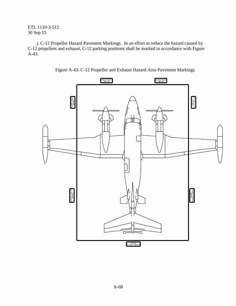
j. C-12 Propeller Hazard Pavement Markings. In an effort to reduce the hazard caused by C-12 propellers and exhaust, C-12 parking positions shall be marked in accordance with Figure A-43.
Figure A-43. C-12 Propeller and Exhaust Hazard Area Pavement Markings

ETL 1110-3-512 30 Sep 15
A-69
Figure A-44. Marking at Static Ground Points
Figure A-45. Aircraft Stop Block and Restricted Area Boundary Marking

ETL 1110-3-512 30 Sep 15
A-70
A-6. Marking of Obstructions to Air Navigation. a. Purpose of Marking. The purpose of marking a structure is to warn aircrews of its presence during daylight hours. To accomplish this objective, it may be necessary to color the structure or indicate its presence by use of suitable markers, flags or lights. (1) Marking of Objects. Mark objects or structures that penetrate an airfield's imaginary surfaces (described in UFC 3-260-01) and to those objects that, by their nature and position constitute a hazard to air navigation in contrasting colors and patterns so they are conspicuous during day visual flight rules (VFR) conditions. These markings should be held to the minimum commensurate with essential operational requirements. Obstruction markings on objects that are not, in fact, obstructions, present false and misleading information and should be eliminated. For guidelines, use FAA AC 70/7460-1, within the continental United States (CONUS), Alaska, Hawaii, or any U.S. Territory. For locations outside the continental United States (OCONUS), use Annex 14 to the Convention on International Civil Aviation Organization, Volume I. (2) Omission of Standard Marking. When high intensity lighting systems are employed in accordance with the standards contained herein, the marking of structures with standard aviation surface orange and white paint and red obstruction lights may be omitted. The high intensity lighting systems are considered to be far more effective than the aviation surface orange and white paint and may therefore be recommended in lieu of standard marking. This is particularly true under certain ambient light conditions and position of the sun relative to direction of flight. b. Shielded Objects. Do not mark obstructions shielded by surrounding objects if you have marked the surrounding objects. Shielded as used in this instruction is defined as, objects that may not need to be marked in obstruction marking colors and patterns if the marking and or lighting of a predominant permanent building, structure, or object is assessed as providing sufficient warning to pilots that, in avoiding the dominant obstruction, they will also avoid the unmarked obstructions in the immediate surrounding area without risk of collision. See FAA AC 70/7460-1, Chapter 5, paragraph "Group of Obstructions.". (1) Partial Marking of Obstructions. Partial marking of obstructions such as storage tanks and chimneys is adequate when the lower portion is hidden by surrounding objects or terrain, or the size of the upper portion is significantly larger than the supporting structure. Do not paint critical surfaces on obstructions, such as ladders, maintenance decks, or radar-sensitive surfaces. (2) Control Structures. Although control tower obstruction lighting must meet the requirements of UFC 3-535-01, Airfield Lighting Systems, marking control towers is not necessary, based on their shape, size, and location. c. Detail Requirements. Only those paint materials will be used that meet the minimum standards established herein.

ETL 1110-3-512 30 Sep 15
A-71
(1) Marking Materials. Obstructions will be marked by the use of surface colors wherever practical. Surface colors will consist of paint conforming to the Federal Specification. Paint shall be appropriate for the material being painted, or reflective tape conforming to Federal Specification LS300. Where marking by surface color is impractical, the general definition and location of the obstructions will be indicated by suitable markers or flag. Aviation surface orange is defined as a color not darker than color chip No. 12197 or lighter than color chip No. 12246, as contained in Federal Standard No. 595. (2) Application. (a) Markings. Painted markings will be applied to obstruction surfaces only after care has been taken to insure that such surfaces are dry and clean. (b) Tape. Reflective tape will be applied according to the manufacturer’s instructions. (c) Alternate Methods of Marking. When impractical to apply the marking material directly to the top 5 feet (1.52 m) of poles or towers, supporting overhead or guy wires, the marking material may be placed on a backlog surface, longitudinally split tube or other mountable device and this may be attached directly to the poles or towers. d. Lighting of Airfields, Heliports, and Obstructions. For criteria on lighting of airfields, heliports and obstructions, see UFC 3-535-01. For joint use facilities, each certificate holder shall ensure that each object in each area within its authority which exceeds any of the heights or penetrates the imaginary surfaces described in Paragraph A-6.a(1) is either removed, marked, or lighted. However, removal, marking and lighting is not required if it is determined to be unnecessary by an FAA aeronautical study. e. Colors. Maximum visibility of an obstruction by contrast in colors can best be obtained by the use of aviation surface orange and white paint. Orange or white enamel paint may be used for marking, provided its chromaticity and luminance factors satisfy Federal Standard, color, as follows: Orange – Number 12197 (aviation surface orange). White – Number 17875 (aviation white). f. Painting. The specifications of surface colors apply only to freshly painted surfaces. Paints used for surface markings usually change with time. While it is not feasible to require strict maintenance, surfaces should be repainted whenever the color changes noticeably or its effectiveness is impaired by scaling or chipping. A color tolerance chart is available for determining when repainting is necessary. The lower portion of structures situated in wooded or sheltered areas are protected to some extent from direct sunshine, blowing sand and sleet, and

ETL 1110-3-512 30 Sep 15
A-72
other atmospheric and environmental elements that tend to deteriorate painted surfaces. Therefore, examination of the ground or bottom band of aviation surface orange paint is not a good indication and should not be used as a criteria for determining when repainting is necessary. (1) Materials and Application. Quality paint materials should be selected to be compatible with the surfaces to be painted, including previous coatings on the surfaces if any, as well as suitable for the environmental service conditions to which it will be subjected. Surface preparation and paint application should be accomplished in accordance with the manufacturer’s recommendations as appropriate for the paint to be used and surface to be coated. (2) Surfaces Not Requiring Paint. If the smooth surface of paint on the ladders, decks and walkways of certain types of steel towers and similar structures presents a potential danger to maintenance personnel, such surfaces need not be painted. Care should be taken so the overall marking effect of the painting is not reduced. Where the painting or the act of painting certain precision or critical surfaces would have an adverse effect on the desired transmission or radiation characteristics of a radio frequency signal, such painting may be omitted. (3) Skeletal Structures. Paint should be applied to all surfaces both ’inner and outer, of the framework in order to be effective. This applies to the supporting structures of overhead transmission lines as well as radio, television and similar skeletal structures. g. Patterns. Patterns of various types are used to mark obstructions to air navigation. Normally, the size and shape of the obstruction will determine the pattern to be used. (1) Solid Pattern. An obstruction the projection of which on any vertical plane has both dimensions less than 10.5 feet (3.20 m) should be colored aviation surface orange. (2) Alternate Bands of Orange and White. See Figure A-46 for alternate bands of aviation surface orange and white are normally displayed on the following structures: (a) Radio and television towers and supporting structures of overhead transmission lines, see paragraph A-6.i.1. (b) Poles. (c) Smokestacks. (d) Skeletal framework of storage tanks and similar structures. (e) Structures which appear narrow from a side view. h. Width of Bands. The width of bands for structures of any height should be equal, provided that each band has a width of not more than 100 feet (30.5 m) nor less than 1.5 feet
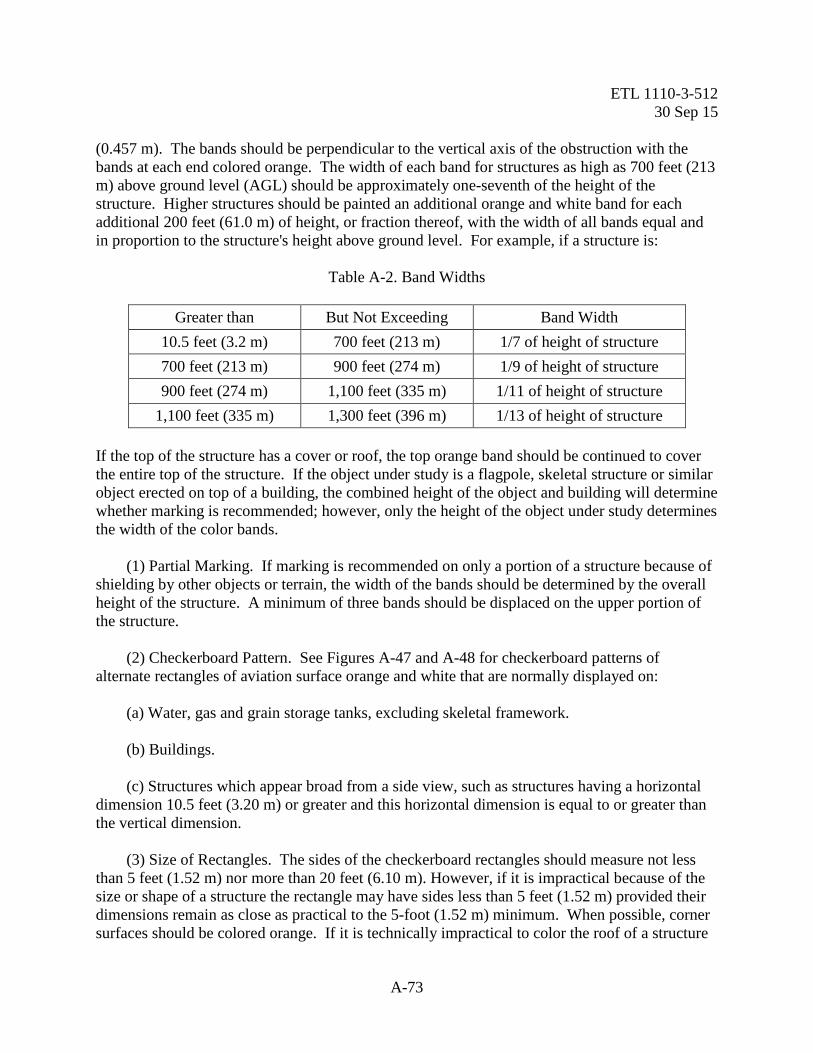
ETL 1110-3-512 30 Sep 15
A-73
(0.457 m). The bands should be perpendicular to the vertical axis of the obstruction with the bands at each end colored orange. The width of each band for structures as high as 700 feet (213 m) above ground level (AGL) should be approximately one-seventh of the height of the structure. Higher structures should be painted an additional orange and white band for each additional 200 feet (61.0 m) of height, or fraction thereof, with the width of all bands equal and in proportion to the structure's height above ground level. For example, if a structure is:
Table A-2. Band Widths
Greater than But Not Exceeding Band Width 10.5 feet (3.2 m) 700 feet (213 m) 1/7 of height of structure 700 feet (213 m) 900 feet (274 m) 1/9 of height of structure 900 feet (274 m) 1,100 feet (335 m) 1/11 of height of structure
1,100 feet (335 m) 1,300 feet (396 m) 1/13 of height of structure If the top of the structure has a cover or roof, the top orange band should be continued to cover the entire top of the structure. If the object under study is a flagpole, skeletal structure or similar object erected on top of a building, the combined height of the object and building will determine whether marking is recommended; however, only the height of the object under study determines the width of the color bands. (1) Partial Marking. If marking is recommended on only a portion of a structure because of shielding by other objects or terrain, the width of the bands should be determined by the overall height of the structure. A minimum of three bands should be displaced on the upper portion of the structure. (2) Checkerboard Pattern. See Figures A-47 and A-48 for checkerboard patterns of alternate rectangles of aviation surface orange and white that are normally displayed on: (a) Water, gas and grain storage tanks, excluding skeletal framework. (b) Buildings. (c) Structures which appear broad from a side view, such as structures having a horizontal dimension 10.5 feet (3.20 m) or greater and this horizontal dimension is equal to or greater than the vertical dimension. (3) Size of Rectangles. The sides of the checkerboard rectangles should measure not less than 5 feet (1.52 m) nor more than 20 feet (6.10 m). However, if it is impractical because of the size or shape of a structure the rectangle may have sides less than 5 feet (1.52 m) provided their dimensions remain as close as practical to the 5-foot (1.52 m) minimum. When possible, corner surfaces should be colored orange. If it is technically impractical to color the roof of a structure

ETL 1110-3-512 30 Sep 15
A-74
in a checkerboard pattern, such roof may be colored orange. If part or all of a spherical shaped structure does not permit the exact application of a checkerboard pattern, then the shape of the new rectangles may be modified to fit the shape of the spherical surface. (4) Exceptions. If the type construction of storage tanks does not permit coloring by a checkerboard pattern, then such obstructions should be colored by alternate bands of orange and white, or a limited checkerboard pattern applied to the upper one third of the structure, provided an aeronautical study indicates that the modified marking will provide adequate protection for air navigation.
Figure A-46. Painting and/or Dual Lighting of Chimneys, Poles, Towers, and Similar Structures

ETL 1110-3-512 30 Sep 15
A-75
Figure A-47. Painting and Lighting of Water Towers, Storage Tanks, and Similar Structures More Than 150 Feet (45 m), but not more than 250 Feet (77m)
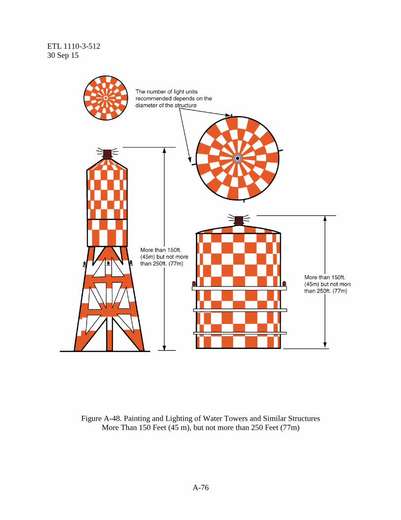
ETL 1110-3-512 30 Sep 15
A-76
Figure A-48. Painting and Lighting of Water Towers and Similar Structures More Than 150 Feet (45 m), but not more than 250 Feet (77m)
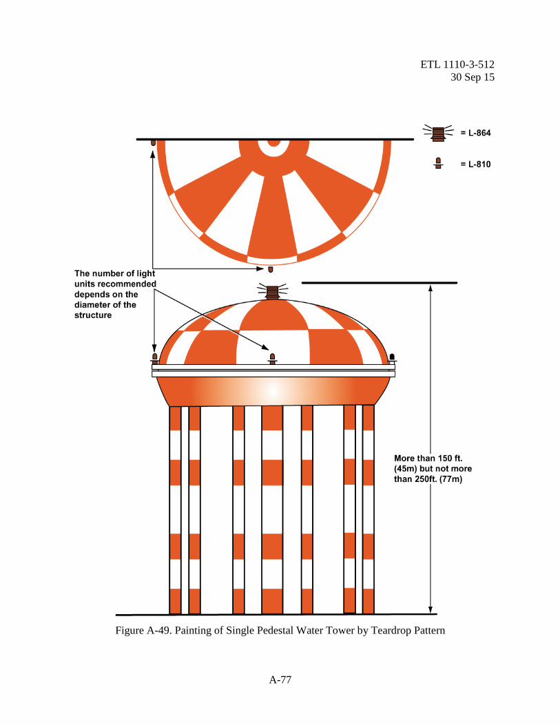
ETL 1110-3-512 30 Sep 15
A-77
Figure A-49. Painting of Single Pedestal Water Tower by Teardrop Pattern
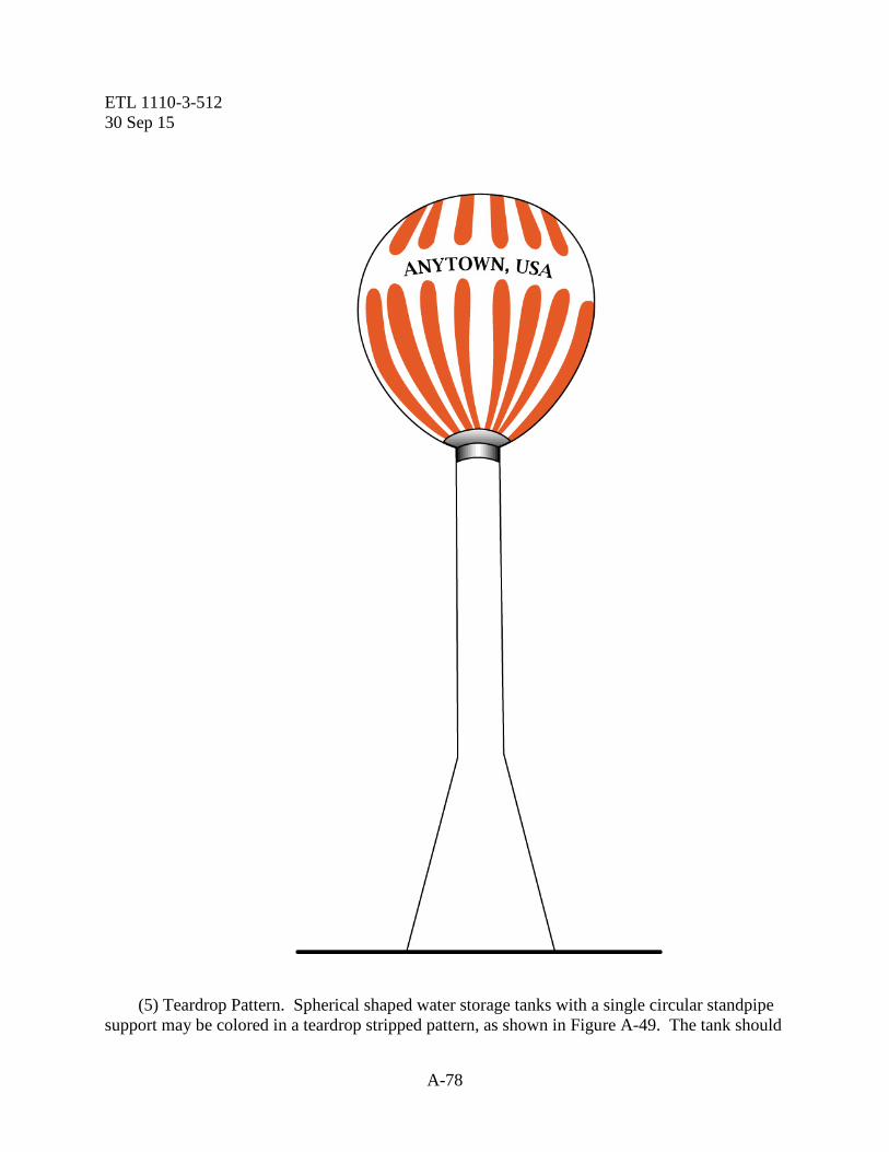
ETL 1110-3-512 30 Sep 15
A-78
(5) Teardrop Pattern. Spherical shaped water storage tanks with a single circular standpipe support may be colored in a teardrop stripped pattern, as shown in Figure A-49. The tank should

ETL 1110-3-512 30 Sep 15
A-79
be colored to show alternate stripes of aviation surface orange and white. The stripes should extend from the top center of the tank to its supporting standpipe. (a) Width of Stripes. The width of the stripes should be equal and the width of each stripe at the greatest girth of the tank should not be less than 5 feet (1.52 m) nor more than 15 feet (4.57 m). (b) Community Name. If it is desirable to paint the name of the community on the side of the tank, the stripe pattern may be broken to serve this purpose. This open area should have a maximum height of 3 feet (0.910 m). i. Markers. Markers should be used to mark obstructions when it has been determined that it is impractical to mark such obstructions by painting. Markers may also be used in addition to aviation surface orange and white colors when it has been determined that such markings should be used to provide protection for air commerce. They should be displayed in conspicuous positions on or adjacent to the obstructions so as to retain the general definition of the obstruction. They should be recognizable in clear air from a distance of at least 1000 feet (305 m) in all directions from which an aircraft is likely to approach. They should be distinctively shaped so they are not mistaken for markers that are used to convey other information. The shape should be such that the hazard they mark is not increased. (1) Spherical Markers. Spherical markers are normally displayed on overhead wires. Markers may be of another shape, provided the projected area of such markers will not be less than that presented by a spherical marker. (a) Display. At least one such marker should be displayed at equal intervals for each 150 feet (45.7 m) or fraction thereof, of the overall length of the overhead line and not lower than the highest wire. The top 5 feet (1.52 m) meet of the poles and towers to which overhead wires or guy wires are attached will be marked. The distance between markers may be increased to not more than 600 feet (183 m) when the overhead wires are located more than 15,000 feet (4,572 m) from the nearest landing area. Where there is more than one overhead wire on which the spheres can be installed, the spheres may be installed alternately along each wire as long as the distance between adjacent spheres meets the spacing standard. This allows the weight and wind loading factors to be distributed. (b) Size and Color. The diameter of the markers should not be less than 20 inches (51 mm) and should be colored aviation orange. (2) Flag Markers. Flags may be used to mark obstructions when it has been determined that the use of coloring or spherical markers is technically impractical. (a) Display. Flag markers should be displayed around, on top of the obstruction or around its highest edge. When flags are used to mark extensive obstructions or closely grouped obstructions, they should be displayed approximately 50 feet (15.2 m) apart.
ETL 1110-3-512 30 Sep 15
A-80
(b) Shape. Flags should be rectangular in shape and have stiffeners to keep them from drooping in calm wind. The flag stakes should be of such strength and height that they will support the flags free of the round, vegetation or nearby surfaces. (c) Color Patterns. Flags should be in one of the following patterns: Solid Color. Aviation surface orange not less than 2 feet (0.610 m) on a side. Orange and White. Two triangular sections, one of aviation surface orange and the other of aviation surface white, combined to form a rectangle not less than 2 feet (0.610 m) on a side. (3) Checkerboard. A checkerboard pattern of aviation surface orange and aviation surface white squares, each 1 foot (0.305 m) plus or minus 10 percent on a side, combined to form a rectangle not less than 3 feet (0.914 m) on a side. j. Special Markings. In addition to the marking recommendations included herein other documents contain appropriate guidelines. (1) Vehicles. FAA Advisory Circular 150/5210-5, Painting, Marking and Lighting of Vehicles Used on an Airport, contains provisions for marking vehicles customarily used on landing areas. (2) FAA Facilities. Obstruction marking for FAA facilities shall conform to FAA Drawing Number D-5480, referenced in Federal Aviation Agency Standard, FAASTD-003, Paint Systems for Structures. (3) Unusual Complexities. The FAA may also recommend appropriate marking in an area where obstructions are so grouped as to present a common hazard to air commerce.

ETL 1110-3-512 30 Sep 15
A-81
THIS PAGE INTENTIONALLY LEFT BLANK


ETL 1110-3-512 1 Sep 15
B-1
APPENDIX B
References B-1. Air Force. All documents available at http://www.e-publishing.af.mil/ a. AFI 13-217, Drop Zone and Landing Zone Operations b. AFI 32-1042, Standards for Marking Airfields c. AFI 32-1043, Standards for Managing, Operating, and maintaining aircraft arresting system. d. ETL 04-02, Standard Airfield Marking Schemes e. ETL 09-6, C-130 and C-17 Landing Zone (LZ) Dimensional, Marking, and Lighting Criteria B-2. Army. Documents available at https://transportation.erdc.dren.mil/tsmcx/criteria.aspx a. Technical Report TSC 13-2 Aircraft Characteristics for Military Aircraft All documents available at http://www.e-publishing.af.mil/ b. AR 420-1 Army Facilities Management c. ETL 1110-3-510 Aviation Complex Planning and Design Criteria for Army Unmanned Aircraft Systems (UAS) d. ETL 1110-3-511 Army Airfield/Heliport Planning and Design Changes e. ATP 5-19 Risk Management B-3. DOD Publications. All documents available at http://www.wbdg.org/ccb/ a. Unified Facilities Criteria (UFC) 3-260-01, Airfield and Heliport Planning and Design, b. Unified Facilities Criteria (UFC) 3-535-01, Visual Air Navigation Facilities

ETL 1110-3-512 1 Sep 15
B-2
c. Unified Facilities Criteria (UFC) 3-260-05a Marking of Army Airfield heliport operational and maintenance facilities B-4. Department of Transportation (DOT). Federal Highway Administration (FHWA): All documents available at http://mutcd.fhwa.dot.gov/ a. Manual on Uniform Traffic Control Devices (MUTCD) for Streets and Highways B-5. Federal Aviation Administration (FAA). All documents available athttp://www.faa.gov/regulations_policies/resources/advisory_circulars/ a. AC 70/7460-1, Obstruction Marking and Lighting b. AC 150/5300-13, Airport Design c. AC 150/5340-1, Standards for Airport Markings d. AC 150/5345-55, Lighted Visual Aid to Indicate Temporary Runway Closure B-6. Federal Specifications. All documents available at; http://www.wbdg.org/ccb/ a. TT-P-1952E, Paint, Traffic and Airfield Marking, Waterborne b. TT-B-1325D, Beads, Retroreflective B-7. North Atlantic Treaty Organization (NATO). All documents available at: http://www.nato.int/docu/standard.htm a. STANAG 3534, Airfield Lighting, Marking and Tone Down System for Non-Permanent Deployed Operations B-8. Air Standardization Coordinating Committee (ASCC). a. Air Standard 90/28, Aerodrome Pavement Markings

ETL 1110-3-512 1 Sep 15
B-3
B-9. International Civil Aviation Organization (ICAO). All documents available at: http://www.icao.int/ a. Annex 14, Volume I, Aerodromes b. Annex 14, Volume II, Heliports
ETL 1110-3-512 1 Sep 15
B-4
THIS PAGE INTENTIONALLY LEFT BLANK
ETL 1110-3-512 1 Sep 15
C-1
APPENDIX C
Definitions The following definitions apply to terms used in this ETL. Airfield. A facility designed and used for the express purpose of operation, Maintenance, and basing of either or both, fixed and rotary wing aircraft. Displaced Threshold. A runway threshold that is not at the beginning of the full-strength runway pavement.and the paved area between the beginning of the full strength pavement and the displaced threshold is used for takeoff or rollout of aircraft. Heliport. A facility designed for the exclusive operating, basing, servicing and maintaining of rotary-wing aircraft (helicopters). The facility may contain a rotary-wing runway and/or helipads. Helipad. A prepared area designated and used for takeoff and landing of helicopters (includes touchdown and hoverpoint.) Instrument Meteorological Conditions (IMC). Meteorological conditions expressed in terms of visibility, distance from cloud, and ceiling less than the minimums specified for visual meteorological conditions (VMC). Joint Use Airfields. A joint use airfield is considered where there is a written agreement between the US Military and local government agency authorizing use of the military runways for public transportation. Nonprecision Instrument Runway. A runway having an existing instrument approach procedure utilizing air navigation facilities with only horizontal guidance for which a straight in nonprecision approach procedure has been approved. Precision Instrument Runway. A runway having an existing instrument approach procedure utilizing a precision instrument landing system. Runway Threshold. The designated beginning of the runway that is available and suitable for the landing of aircraft. Relocated Threshold. A threshold that is located at a point on the runway other than the beginning of the full strength pavement and the paved area between the former threshold and the relocated threshold is no longer used for landing or takeoff of aircraft.
ETL 1110-3-512 1 Sep 15
C-2
Retroreflective. The property of a material that indicates its ability to reflect light so that the paths of the rays are returned to the source on a plane parallel to the incident rays. Runway/Runway Hold Position. An aircraft holding position designated on a runway which intersects with another runway. It is used to protect against incursions on the primary runway when the intersecting secondary runway is used for taxiing or "land and hold short" operations. Shielded. As used in this instruction, “shielded” refers to objects that may not need to be marked in obstruction marking colors and patterns if the marking and or lighting of a predominant permanent building, structure, or object is assessed as providing sufficient warning to pilots that, in avoiding the dominant obstruction, they will also avoid the unmarked obstructions in the immediate surrounding area without risk of collision. Visual Flight Rules (VFR). Rules that govern the procedures for conducting flight under visual conditions. This term is also used in the United States to indicate weather conditions that are equal to or greater than minimum VFR requirements. Visual Meteorological Conditions (VMC). Weather conditions in which visual flight rules apply; expressed in terms of visibility, ceiling height, and aircraft clearance from clouds along the path of flight. Also see Visual Flight Rules. Visual Runway. A runway having no straight-in instrument approach procedure and intended solely for the operation of aircraft using visual approach procedure.