Embed Size (px)
Citation preview
E T H E R N E T / U S B -
I N T E R F A C E
H O 7 3 0
Installation guidelines
English

2Änderungen vorbehalten
G e n e r a l i n f o r m a t i o n r e g a r d i n g t h e C E m a r k i n g
General information regarding the CE marking
HAMEG instruments fulfi ll the regulations of the EMC directive. The conformity test made by HAMEG is based on the actual generic- and product standards. In cases where different limit values are applicable, HAMEG applies the severer standard. For emission the limits for residential, commercial and light industry are applied. Regarding the immunity (susceptibility) the limits for industrial environment have been used.
The measuring- and data lines of the instrument have much infl uence on emmission and immunity and therefore on meeting the acceptance limits. For different applications the lines and/or cables used may be different. For measurement operation the following hints and conditions regarding emission and immunity should be observed:
1. Data cablesFor the connection between instruments resp. their interfaces and external devices, (computer, printer etc.) suffi ciently screened cables must be used. Without a special instruction in the manual for a reduced cable length, the maximum cable length of a dataline must be less than 3 meters and not be used outside buildings. If an interface has several connectors only one connector must have a connection to a cable.Basically interconnections must have a double screening. For IEEE-bus purposes the double screened cables HZ72S and HZ72L from HAMEG are suitable.
2. Signal cablesBasically test leads for signal interconnection between test point and instrument should be as short as possible. Without instruction in the manual for a shorter length, signal lines must be less than 3 meters and not be used outside buildings.Signal lines must screened (coaxial cable - RG58/U). A proper ground connection is required. In combination with signal generators double screened cables (RG223/U, RG214/U) must be used.
3. Infl uence on measuring instruments.Under the presence of strong high frequency electric or magnetic fi elds, even with careful setup of the measuring equipment an infl uence of such signals is unavoidable.This will not cause damage or put the instrument out of operation. Small deviations of the measuring value (reading) exceeding the instruments specifi cations may result from such conditions in individual cases.
HAMEG Instruments GmbH
KONFORMITÄTSERKLÄRUNGDECLARATION OF CONFORMITYDECLARATION DE CONFORMITE
DECLARACIÓN DE CONFORMIDAD
Hersteller / Manufacturer / Fabricant / Fabricante: HAMEG Instruments GmbH · Industriestraße 6 · D-63533 Mainhausen
Die HAMEG Instruments GmbH bescheinigt die Konformität für das Produkt The HAMEG Instruments GmbH herewith declares conformity of the product HAMEG Instruments GmbH déclare la conformite du produit HAMEG Instruments GmbH certifi ca la conformidad para el producto
Bezeichnung: Ethernet/USB-InterfaceProduct name: Ethernet/USB InterfaceDesignation: Interface Ethernet/USBDescripción: Interfaz Ethernet/USB
Typ / Type / Type / Tipo: HO730
mit / with / avec / con: HM1008, HM1508, HM1508-2, HM2008Optionen / Options / Options / Opciónes: –
mit den folgenden Bestimmungen / with applicable regulations / avec les directives suivantes / con las siguientes directivas:
EMV Richtlinie 89/336/EWG ergänzt durch 91/263/EWG, 92/31/EWG EMC Directive 89/336/EEC amended by 91/263/EWG, 92/31/EEC Directive EMC 89/336/CEE amendée par 91/263/EWG, 92/31/CEE Directiva EMC 89/336/CEE enmendada por 91/263/CEE, 92/31/CEE
Niederspannungsrichtlinie 73/23/EWG ergänzt durch 93/68/EWG Low-Voltage Equipment Directive 73/23/EEC amended by 93/68/EECDirective des equipements basse tension 73/23/CEE amendée par 93/68/CEEDirectiva de equipos de baja tensión 73/23/CEE enmendada por 93/68/EWG
Angewendete harmonisierte Normen / Harmonized standards applied / Normes harmonisées utilisées / Normas armonizadas utilizadas:
Sicherheit / Safety / Sécurité / Seguridad:
EN 61010-1:2001 / IEC (CEI) 1010-1:2001Überspannungskategorie / Overvoltage category / Catégorie de surtension / Categoría de sobretensión: II
Verschmutzungsgrad / Degree of pollution / Degré de pollution / Nivel de polución: 2
Elektromagnetische Verträglichkeit / Electromagnetic compatibility / Compatibilité électromagnétique / Compatibilidad electromagnética:
EN 61326-1/A1: Störaussendung / Radiation / Emission: Tabelle / table / tableau 4; Klasse / Class / Classe / classe B.
Störfestigkeit / Immunity / Imunitee / inmunidad: Tabelle / table / tableau / tabla A1.
EN 61000-3-2/A14: Oberschwingungsströme / Harmonic current emissions / Émissions de courant harmonique / emisión de corrientes armónicas: Klasse / Class / Classe / clase D.
EN 61000-3-3: Spannungsschwankungen u. Flicker / Voltage fl uctuations and fl icker / Fluctuations de tension et du fl icker / fl uctuaciones de tensión y fl icker.
Datum / Date / Date / Fecha 26. 09. 2006 Unterschrift / Signature / Signatur / Signatura
Manuel Roth Manager

3Änderungen vorbehalten
English
Declaration of conformity 2
General information regarding the CE marking 2
2. Safety Hints 4
3. Interface Description 4
3.1 Ethernet 4
3.2 USB 4
4. Oscilloscope Firmware 4
5. Interface Fitting Instruction 5
5.1 Removing the existing interface 5
5.2 Fitting the interface HO730 5
6. Interface Selection 6
7. USB-Driver Installation 7
7.1 Installation under Windows XP: 7
8. Ethernet confi guration 9
8.1 IP networks (IP – Internet protocol) 9
8.2 Ethernet interface parameters at the oscilloscope 10
8.3 Ethernet interface parameters at the host (PC) 11
8.4 Test of the connection to the oscilloscope 12
9. Application 12
C o n t e n t
4Änderungen vorbehalten
2. Safety Hints
STOP
Attention! Fitting or exchanging of an interface must not be
made unless the oscilloscope is switched off and not connected to line (mains).
STOP
Attention! During operation the interface opening must be
closed.
STOP
Attention! All interface connections are galvanically connected
to the scope.
STOP
Measurement at high potentials is prohibited and endangers the scope, the interface and all equip-ment connected to the interface.
If the safety rules are disregarded, any damage to HAMEG In-struments GmbH products will void the warranty. Consequently HAMEG Instruments GmbH will not take any responsibility for damage to people or equipment of other make.
3. Interface Description
HO730 is a DUAL Interface that can be used either as an Ether-net or as a USB 2.0 / 1.1 Interface. It is used with the HAMEG CombiScopes HM1008 and HM1508 for data transfer and oscilloscope control. Only one function (Ethernet or USB) - not both at the same time - can be activated (see item 6 “Interface Selection”).
3.1 Ethernet
The interface is equipped with an Ethernet type RJ-45 connector according to IEEE standard 802.3. For the direct connection with a host (PC) or indirect connection over a SWITCH, a doubly protected network cable (e.g. CAT.5, CAT.5e, CAT.5+, CAT.6 or CAT.7) is required, equipped with an Ethernet plug type the RJ-45 at each end. Either an uncrossed or a crossed network cable (cross over cable) can be used.
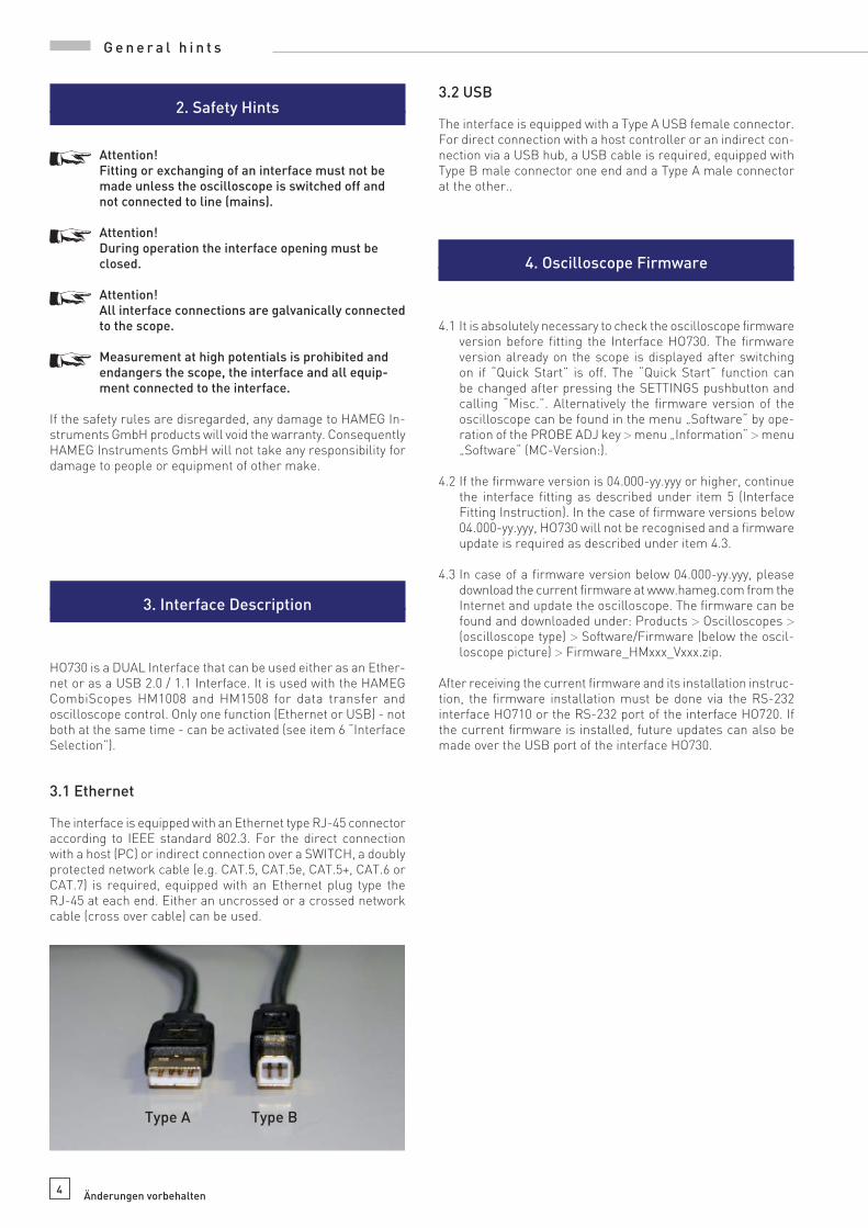
3.2 USB
The interface is equipped with a Type A USB female connector. For direct connection with a host controller or an indirect con-nection via a USB hub, a USB cable is required, equipped with Type B male connector one end and a Type A male connector at the other..
4. Oscilloscope Firmware
4.1 It is absolutely necessary to check the oscilloscope fi rmware version before fi tting the Interface HO730. The fi rmware version already on the scope is displayed after switching on if “Quick Start” is off. The “Quick Start” function can be changed after pressing the SETTINGS pushbutton and calling “Misc.”. Alternatively the fi rmware version of the oscilloscope can be found in the menu „Software“ by ope-ration of the PROBE ADJ key > menu „Information“ > menu „Software“ (MC-Version:).
4.2 If the fi rmware version is 04.000-yy.yyy or higher, continue the interface fi tting as described under item 5 (Interface Fitting Instruction). In the case of fi rmware versions below 04.000-yy.yyy, HO730 will not be recognised and a fi rmware update is required as described under item 4.3.
4.3 In case of a fi rmware version below 04.000-yy.yyy, please download the current fi rmware at www.hameg.com from the Internet and update the oscilloscope. The fi rmware can be found and downloaded under: Products > Oscilloscopes > (oscilloscope type) > Software/Firmware (below the oscil-loscope picture) > Firmware_HMxxx_Vxxx.zip.
After receiving the current fi rmware and its installation instruc-tion, the fi rmware installation must be done via the RS-232 interface HO710 or the RS-232 port of the interface HO720. If the current fi rmware is installed, future updates can also be made over the USB port of the interface HO730.
Type A Type B
G e n e r a l h i n t s

5Änderungen vorbehalten
5. Interface Fitting Instruction
STOP
Safety! The following procedures must only be carried out
on condition that the mains (line) power cable is not connected to the oscilloscope and no connection is made at the measurement inputs.
STOP
Attention! To avoid damage of the interface during removing
and fi tting by electrostatic discharge, please link a metal part of the oscilloscope to equalise potentials between oscilloscope and your body. Maintain this connection during the fi tting/removing!
Only touch the interface at its mounting panel!
5.1 Removing the existing interface
5.1.1 Remove both fastening screws.
5.1.2 Pull out the interface.
5.2 Fitting the interface HO730
5.2.1 Insert the interface HO730 in the opening in such a way, that the PCB will be inserted in the guides - visible on both sides – and push it in completely.
5.2.2 Fit the interface with the fastening screws previously (item 4.1.1) removed.
F i t t i n g o f t h e H O 7 3 0

6Änderungen vorbehalten
6. Interface Selection
6.1 Interface SelectionPress the SETTINGS pushbutton to call the “Settings” menu. The function key “Interface” opens the submenu “Settings Interface” consisting of the menu items USB and Ethernet.
6.1.1 EthernetIf Ethernet is highlighted, this interface is activated. With the activating of Ethernet the menu option „Parameter“ also ap-pears additional in the Readout, which the Ethernet interface parameter settings made possible (see section 8).
Reference!The host (PC) must have an Ethernet LAN interface inserted. For the confi guration of this interface you will fi nd further in-formation in its PC manual or in the manual of your network interface.
6.1.2 USBUSB is selected when highlighted. Further settings are not required.
I n t e r f a c e s e l e c t i o n
7Änderungen vorbehalten
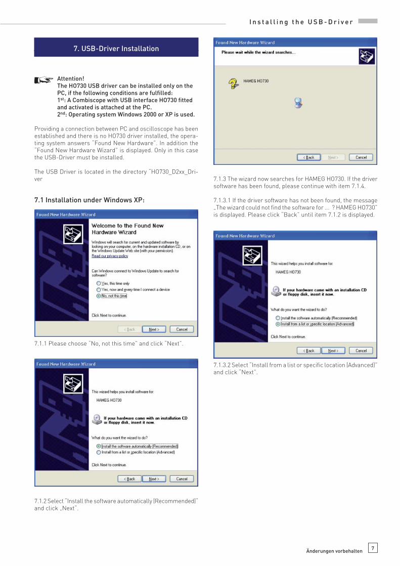
7. USB-Driver Installation
STOP
Attention! The HO730 USB driver can be installed only on the
PC, if the following conditions are fulfi lled: 1st: A Combiscope with USB interface HO730 fi tted
and activated is attached at the PC. 2nd: Operating system Windows 2000 or XP is used.
Providing a connection between PC and oscilloscope has been established and there is no HO730 driver installed, the opera-ting system answers “Found New Hardware”. In addition the “Found New Hardware Wizard” is displayed. Only in this case the USB-Driver must be installed.
The USB Driver is located in the directory “HO730_D2xx_Dri-ver
7.1 Installation under Windows XP:
7.1.1 Please choose “No, not this time” and click “Next”.
7.1.2 Select “Install the software automatically (Recommended)“ and click „Next“.
7.1.3 The wizard now searches for HAMEG HO730. If the driver software has been found, please continue with item 7.1.4.
7.1.3.1 If the driver software has not been found, the message „The wizard could not fi nd the software for ... ? HAMEG HO730” is displayed. Please click “Back” until item 7.1.2 is displayed.
7.1.3.2 Select “Install from a list or specifi c location (Advanced)” and click “Next”.
I n s t a l l i n g t h e U S B - D r i v e r

8Änderungen vorbehalten
I n s t a l l i n g t h e U S B - D r i v e r
7.1.3.3 “Browse” for the selected drive and select the folder containing the driver. Confi rm with “OK”.
7.1.3.4 After the selected path is displayed click “Next”.
7.1.4 Thereafter the “Hardware Installation” window is displa-yed, showing a warning to continue the installation procedure. As this warning is irrelevant in case of HO730 driver software, click „Continue Anyway“.
7.1.5 The wizard installs the driver software.
7.1.6 Please click “Finish” to complete the installation.

9Subject to change without notice
class adress range net quota host quota max. number of networks max. number of hosts
A 0.0.0.1 - 127.255.255.255 8 Bit 24 Bit 126 16.777.214
B 128.0.0.1 - 191.255.255.255 16 Bit 16 Bit 16.384 65.534
C 192.0.0.1 - 223.255.255.255 24 Bit 8 Bit 2.097.151 254
D 224.0.0.1 - 239.255.255.255 Reserved for multicast applications
E 240.0.0.1 - 255.255.255.255 Reserved for special applications
Table 2: Classes of IP adresses
Table 1: Private IP adress ranges
adress range subnetz mask CIDR way of writing number of possible host adresses
10.0.0.0 –10.255.255.255 255.0.0.0 10.0.0.0/8 224 − 2 = 16.777.214
172.16.0.0 –172.31.255.255 255.240.0.0 172.16.0.0/12 220 − 2 = 1.048.574
192.168.0.0 –192.168.255.255 255.255.0.0 192.168.0.0/16 216 − 2 = 65.534
255.255.255.0 192.168.0.0/24 281 − 2 = 254
8. Ethernet confi guration
STOP
Reference! The host (PC) must have an Ethernet LAN interface
inserted. For the confi guration of this interface you will fi nd further information in its PC manual or in the manual of your network interface.
8.1 IP networks (IP – Internet protocol)
In order that two or several network elements (e.g. measuring instruments, host/PC‘s, …) can communicate over a network with one another, some fundamental connections have to be considered, so that data communication is error free and un-impaired.
For each element in a network an IP address has to be assigned, so that they can exchange data among themselves. IP addresses are represented (with the IP version 4) as four decimal numbers separated by points (e.g. 192.168.15.1). Each decimal number is represented by a binary number of 8 bits. IP addresses are divided into public and private address ranges. Public IP addres-ses will be able to route by the Internet and an Internet service Provider (ISP) can to be made available. Public IP addresses can be reached directly over the Internet to directly exchange internet data. Private IP addresses are not routed by the Internet and are reserved for private networks. Network elements with private IP addresses cannot be reached directly over the Internet so no data can be directly exchanged over the Internet. To allow network elements with a private IP address to exchange data over the Internet, they require a router for IP address conversion (English NAT; Network address translation), before connection to the Internet. The attached elements can then data exchange over this router, which possesses a private IP address (LAN IP address) and also a public IP address (WAN IP address), via the Internet. If network elements exchange data only over a local network (without connection with the Internet), appropriate use private IP addresses. Select in addition e.g. a private IP address for the oscilloscope and a private IP address for the host (PC), with which you would like to control the oscilloscope. If you might connect your private network with the Internet later via a router, the private IP addresses used in your local network can be maintained. Since within each IP address range the fi rst IP address is used as network IP address and the last IP address is used as Broadcast IP address, in each case two IP addresses have to be taken off from the “number of possible host addresses“ (see table 1: Private IP address ranges).
Apart from the organization of IP addresses into public and pri-vate address ranges, IP addresses are also divided into classes (Class: A, B, C, D, E). Within the classes A, B, and C are also include the private IP of address ranges described before. The categorisation from IP addresses is for the assignment of public IP address ranges of importance and essentially depends on the size of a local network (maximum number of hosts in the network), which is to be connected with the Internet (see table 2: Classes of IP addresses).
IP addresses can fi x (statically) or variable (dynamically) to be assigned. If IP addresses in a network are assigned fi x, an IP address must be preset manually with each network element. If IP addresses in a network are assigned to the attached network elements automatically (dynamically), a DHCP server (English DHCP becomes; Dynamic Host Confi guration Protocol) is required for the dispatching of IP addresses. With a DHCP server an IP address range for the automatic dispatching of IP addresses can be preset. A DHCP server is usually already integrated in a router (DSL router, ISDN router, Modem router, WLAN router, …) integrated. If a network element (e.g. an oscil-loscope) is connected by a network cable directly with a host (PC), the IP addresses cannot be assigned to the oscilloscope and the host (PC) automatically, since no network with DHCP server is present here. They have to be preset therefore at the oscilloscope and at the host (PC) manually.
IP addresses are divided by using subnet mask into a network quota and into a host quota, so similarly e.g. a telephone number is divided in pre selection (land and local area network number) and call number (user number). Subnet mask have the same form as IP addresses. They are represented with four decimal numbers separated by points (e.g. 255.255.255.0). As is the case for the IP addresses here each decimal number represents a binary number of 8 bits. The separation between network quota and host quota is determined by the subnet mask within an IP address (e.g. the IP address 192.168.10.10 by the subnet mask 255.255.255.0 is divided into a network quota 192.168.10.0 and a host quota of 0.0.0.10). The allocation takes place via the trans-formation of the IP address and the subnet mask in binary form and afterwards a bit by bit one logical AND operation between IP address and subnet mask. The result is the network quota of the IP address. The host quota of the IP address takes place via the bit by bit logical NAND operation between IP address and subnet mask. By the variable allocation of IP addresses in network quota and host quota via subnet masks, one can specify IP address ranges individually for large and small networks. Thus one can operate large and small IP networks and connect if necessary to the Internet via a router. In smaller local networks the subnet mask 255.255.255.0 is mostly used. Network quota (the fi rst 3 numbers) and host quota (the last number) are simple
E t h e r n e t c o n f i g u r a t i o n

10 Subject to change without notice
here without much mathematical expenditure to determine and it can with these subnet mask up to 254 network elements (e.g. measuring instruments, hosts/PC‘s...) in a network be operated at the same time.
Often also a standard gateway is present in a network. In most local networks is this gateway with the router to the Internet (DSL router, ISDN router, …) …) is identical. Using this (gate-way -) router a connection can be manufactured with another network. Thus also network elements, which are not in the same (local) network, can be reached and/or network elements from the local network are able to exchange data with network elements from other networks. For a network-spreading data exchange the IP address of the standard gateway must also be preset. In local networks, mostly the fi rst IP address within a network for this (gateway -) router is used. Mostly routers in a local network to be used as gateway have an IP address with a „1“ in the last place of the IP address (e.g. 192.168.10.1).
8.2 Ethernet interface parameters at the oscil-loscope
The Ethernet interface parameters are preset in the oscil-loscope with activated Ethernet interface in the menu “SET-TINGS“ “INTERFACE“ “ETHERNET PARAMETER“ to be preset. The Ethernet interface parameters have to agree with the software HMLab and/or the parameters of the Ethernet LAN interface at the host (PC).
Reference! The preset IP addresses in the oscilloscope and the host (PC) have to be different and be in the same subnet (ex.: oscilloscope 192.168.010.010, PC 192.168.010.002, with subnet mask 255.255.255.000).
With activated DHCP function the parameters IP address, sub-net mask and gateway will be automatic by an existing DHCP server in the network.
With deactivated DHCP function the parameters at the Ethernet interface can be preset manually.
Reference! If the oscilloscope is connected by a network cable directly with a host (PC), the DHCP function has to be deac-tivated, since no network with DHCP server is present. Without DHCP server no interface parameters can be made available to the oscilloscope and the host (PC) automatically.
Selecting an interface parameter takes place with the function key ↓ .Selecting the position within an interface parameter takes place with the function key → .
The highlighted parameter value is then preset with the „IN-TENS“ rotation control to the desired value. The menu option “Save“ in the Readout saves the preset interface parameters by the oscilloscope and/or determined automatically after press the menu option “Save“ with activated DHCP function and sto-red until changed. The menu option “Defaults“ in the Readout, restores the factory-installed preset interface parameters.
The represented interface parameters have the following meaning:
IP: The IP address of the oscilloscope (default setting: 192.168.010.010).
Subnet mask: The subnet mask marks the fi rm network quota and the variable host quota of the IP address of theoscilloscope (default setting: 255.255.255.000). General is to be considered: Within a local network (LAN) the preset subnet mask has to be alike with all attached network elements. That applies tooscilloscope and host (PC), if they are in the same local network.
Gateway: The IP address of the gateway (e.g. an existing rou-ter) in the network, in order to make a connection possible with another network (default setting: 192.168.010.001).
IP Port: For the software HMLab or for internally developed TCP (or UDP) applications, can be set the used IP Port. Thus the oscilloscope can be addressed via the preset IP Port directly by an application e.g. 192.168.010.010:50000 (default setting: IP Port 50000). Port settings are possible within the range of 1024 - 65535.
HTTP Port: The HTTP Port for Web browser (default setting: HTTP Port 00080). Port settings are possible within the range of 0 - 65535.
Transfer: The transmission rate of the Ethernet interface (default setting: Auto). In the preset „Auto“ the highest possible transmission rate of the receiving station is selected. If an automatic preset is not possible, transmission rate and the transmission method can be set manually to the following va-lues: 10Mbit/s half duplex, 10Mbit/s full duplex, 100Mbit/s half duplex or 100Mbit/s full duplex. As a check on RJ-45 socket the up-to-date preset transmission rate of the Ethernet interface can be read off in the Readout or from the two light emitting diodes (LED). The yellow LED shines with a transmission rate of 10Mbit/s. The yellow and green LED shines with a transmission rate 100Mbit/s.
Link: The status of the connection between the Ether-net interface of the oscilloscope and the network interface of a receiving station (connection active: Yes, connection not active: No).
STOP
Reference! The MAC address (network card address) of the
Ethernet interface can be queried over the menu „Component tester > Information > Interface“.
I n s t a l l i n g t h e U S B - D r i v e r
11Subject to change without notice
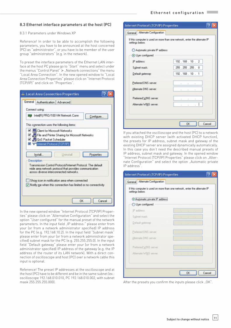
8.3 Ethernet interface parameters at the host (PC)
8.3.1 Parameters under Windows XP
Reference! In order to be able to accomplish the following parameters, you have to be announced at the host concerned (PC) as “administrator“, or you have to be member of the user group “administrators“ (e.g. in the network).
To preset the interface parameters of the Ethernet LAN inter-face at the host PC please go to “Start“ menu and select under the menus “Control Panel“ > „Network connections“ the menu “Local Area Connection“. In the new opened window to “Local Area Connection Properties“ please click on “Internet Protocol (TCP/IP)“ and click on “Properties“.
In the new opened window “Internet Protocol (TCP/IP) Proper-ties“ please click on “Alternative Confi guration“ and select the option “User confi gured“ for the manual preset of the network parameters. In the input fi eld „IP address:“ please enter from your (or from a network administrator specifi ed) IP address for the PC (e.g. 192.168.10.2). In the input fi eld “Subnet mask“ please enter from your (or from a network administrator spe-cifi ed) subnet mask for the PC (e.g. 255.255.255.0). In the input fi eld “Default gateway“ please enter your (or from a network administrator specifi ed) IP address of the gateway (e.g. the IP address of the router of its LAN network). With a direct con-nection of oscilloscope and host (PC) over a network cable this input is optional.
Reference! The preset IP addresses at the oscilloscope and at the host (PC) have to be different and be in the same subnet (ex.: oscilloscope 192.168.010.010, PC 192.168.010.002, with subnet mask 255.255.255.000).
If you attached the oscilloscope and the host (PC) to a network with existing DHCP server (with activated DHCP function), the presets for IP address, subnet mask and gateway of the existing DHCP server are assigned dynamically automatically. In this case you don’t need the described manual presets of IP address, subnet mask and gateway. In the opened window “Internet Protocol (TCP/IP) Properties“ please click on „Alter-nate Confi guration“ and select the option „Automatic private IP address“.
After the presets you confi rm the inputs please click „OK“.
E t h e r n e t c o n f i g u r a t i o n

12 Subject to change without notice
8.4 Test of the connection to the oscilloscope
For the test of the connection of the host (PC) to the Ethernet interface of the oscilloscope, please go into the menu “Start“ and select “Run“. Start the command interpreter by the input of the instruction “cmd“ into the input fi eld. Complete the sequence by the “Enter“ key or confi rm the input by clicking OK.
It opens an input window. After the input character you give to confi rm the instruction “ping 192.168.10.10“ (in the represented example the Ethernet interface of the oscilloscope has the IP address 192.168.10.10) and confi rm the input with Enter.
If the Ethernet interface answers the example represented by the oscilloscope to the “Ping“ instruction without errors as in, the connection is correct. If the interface does not answer attainable e.g. with an error message, no connection is present or the connection is disturbed. In this case please examine all network cables between oscilloscope and host (PC), as well as the preset interface parameters of the Ethernet interface with the oscilloscope and the Ethernet LAN interface with the host (PC). If the connection over further network elements e.g. switches, routers, network servers, etc. is used, examine if necessary these further connections, as well as the presets of the appropriate network elements.
9. Application
In combination with HMLab 1.0 or higher, the interface HO730 can be used via Ethernet as well as USB. The HMLab settings have to correspond with the interface settings of the oscil-loscope. With HMLab an oscilloscope or several oscilloscopes can be operated at the same time, if these are connected by a common LAN network. Likewise an oscilloscope or also several oscilloscopes can be operated at the same time, if they are atta-ched over USB or the LAN-/WAN networks are distributed over several LAN-/WAN networks among themselves with switches and/or routers (e.g. over the Internet) connected.
The interface HO730 has also a Web server, which can be used with a Web browser (e.g. Internet Explorer, …). The following func-tions are supported by the Web server (only in digital mode):– Indicate the equipment data– Selections of the Readout and save over Web browser func-
tion– Control and inquiry with programming instructions (SCPI
instructions) over input mask
Indicate the equipment data
Selections of the Readout and save over Web browser func-tion
E t h e r n e t c o n f i g u r a t i o n

13Subject to change without notice
Control and inquiry with programming instructions (SCPI instructions) over input mask
If the present HMLab version is below 1.0 the current version can be found in the Internet (www.hameg.com) for downloading and updating your PC. The path of the software is: Products > Oscilloscopes > (oscilloscope type) > Software/Firmware (below the oscilloscope picture) > Software/Firmware (below the oscilloscope picture) > HMLab.zip.
The programming commands list will be provided in the Internet under www.hameg.com.
Mainhausen, Germany
August 2006
A p p l i c a t i o n

14 Subject to change without notice

15Änderungen vorbehalten
A p p l i c a t i o n

w w w . h a m e g . d eSubject to change without notice
29-09-2006-gw HAMEG Instruments GmbH
© HAMEG Instruments GmbH Industriestraße 6
A Rohde & Schwarz Company D-63533 Mainhausen
® registered trademark Tel +49 (0) 61 82 800-0
DQS-Certifi cation: DIN EN ISO 9001:2000 Fax +49 (0) 61 82 800-100
Reg.-Nr.: 071040 QM [email protected]
authorized dealer
Oscilloscopes
Spectrum Analyzer
Power Supplies
Modular System
8000 Series
Programmable Instruments
8100 Series