Embed Size (px)
Citation preview

IAIA-EN-I-2015-001-01
Introduction Page 1
Ethernet/IP Add-On Instruction (AOI) and User-defined Data Type (UDT) installation for:
ACON, PCON, and SCON controllers, -CA models and later. The SCON-CB-F servo press controller is not covered in these instructions.
MCON-C, MSCON-C, and MSEP-C multi-axis controllers
ERC3, RCP6S, and Robonet Gateways
Introduction
The provided UDT’s and AOI’s are for the IAI controllers listed above with an Ethernet I/P option, operating in Full-Direct communication mode only. Some IAI documents also refer to this mode as Direct Indication or Direct Numerical Indication mode.
IAI Ethernet/IP devices support implicit messaging only and function as an adapter (slave) device. The Allen-Bradley PLC functions as an implicit message scanner (master) device.
The AOI’s and UDT’s are exported as .L5X files from RSLogix5000 version 20 and can be imported into any RSLogix5000 or Studio 5000 Logix Designer program. The AOI’s and UDT’s are not locked; you can edit them to fit your specific needs.
Contents (these are links; click to jump to a topic) Introduction ............................................................................................................................................................................ 1
1. Requirements & Information .......................................................................................................................................... 2
1.1. Software and hardware .......................................................................................................................................... 2
1.2. Reference documents ............................................................................................................................................. 2
1.3. Feedback and revisions ........................................................................................................................................... 2
2. Single-Axis Positioning Controllers (-CA models and later): ACON, DCON, PCON, SCON ............................................... 3
2.1. Configure the Controller ......................................................................................................................................... 3
2.2. Add the Controller to RSLogix. ................................................................................................................................ 4
2.3. Import the AOI’s and UDT’s .................................................................................................................................... 6
2.4. Create Tags to Utilize the UDT’s ............................................................................................................................. 9
3. Controllers with Gateways, and Gateway Devices ....................................................................................................... 14
3.1. Configure the Gateway. ........................................................................................................................................ 14
3.2. Add the controller to RSLogix 5000. ..................................................................................................................... 22
3.3. Import the Axis AOI’s ............................................................................................................................................ 24
3.4. Import the Gateway UDT’s ................................................................................................................................... 26
3.5. Create Tags to Use the UDT’s and AOI’s ............................................................................................................... 27
4. Programming Information ............................................................................................................................................ 31
4.1. Communication Errors .......................................................................................................................................... 31

IAIA-EN-I-2015-001-01
Requirements & Information Page 2
4.2. Using the AOI’s and UDT’s .................................................................................................................................... 32
4.3. Troubleshooting .................................................................................................................................................... 33
1. Requirements & Information
1.1. Software and hardware
1.1.1. IAI PC Interface Software for RC and an IAI programming cable. The controllers cannot be set up using their Ethernet ports.
1.1.2. IAI Gateway Parameter Configuration Tool (for gateway controllers and devices only).
1.1.3. Ethernet hub, router, or switch. You cannot connect a PLC and controller directly unless the cable is a crossover type.
1.1.4. Cat-5+ connection cables for PC, PLC, and the controller(s).
1.1.5. Rockwell Software RSLogix5000 or Studio5000 programming software. This document uses graphics copied from version 20.01. Later versions may appear different.
1.1.6. It is not necessary to load EDS files because we will use the built-in generic Ethernet module driver of the Rockwell Software.
1.2. Reference documents
1.2.1. IAI manual ME0278 Ethernet/IP Operation, for positioning controllers.
1.2.2. IAI manual ME0155 PC Interface Software for RC.
1.2.3. IAI manual for the controller you have.
1.2.4. Allen-Bradley manual for the PLC model you have.
1.2.5. Allen-Bradley manual 1756-PM010E-EN-P, Logix5000 Controllers Add-On Instructions.
1.3. Feedback and revisions
1.3.1. Feedback is greatly appreciated. If you find mistakes in the AOI’s, UDT’s, or this document, or you have suggestions for improvement, please contact John Stump at [email protected] or 888-354-9470.
1.3.2. The latest revision of this document is: June 23, 2017.
IAIA-EN-I-2015-001-01
Single-Axis Positioning Controllers (-CA models and later): ACON, DCON, PCON, SCON Page 3
2. Single-Axis Positioning Controllers (-CA models and later): ACON, DCON, PCON, SCON
2.1. Configure the Controller
The examples use a PCON controller but the same examples apply to the other controllers listed.
2.1.1. Connect to the controller with a programming cable and run the PC Interface Software for RC application.
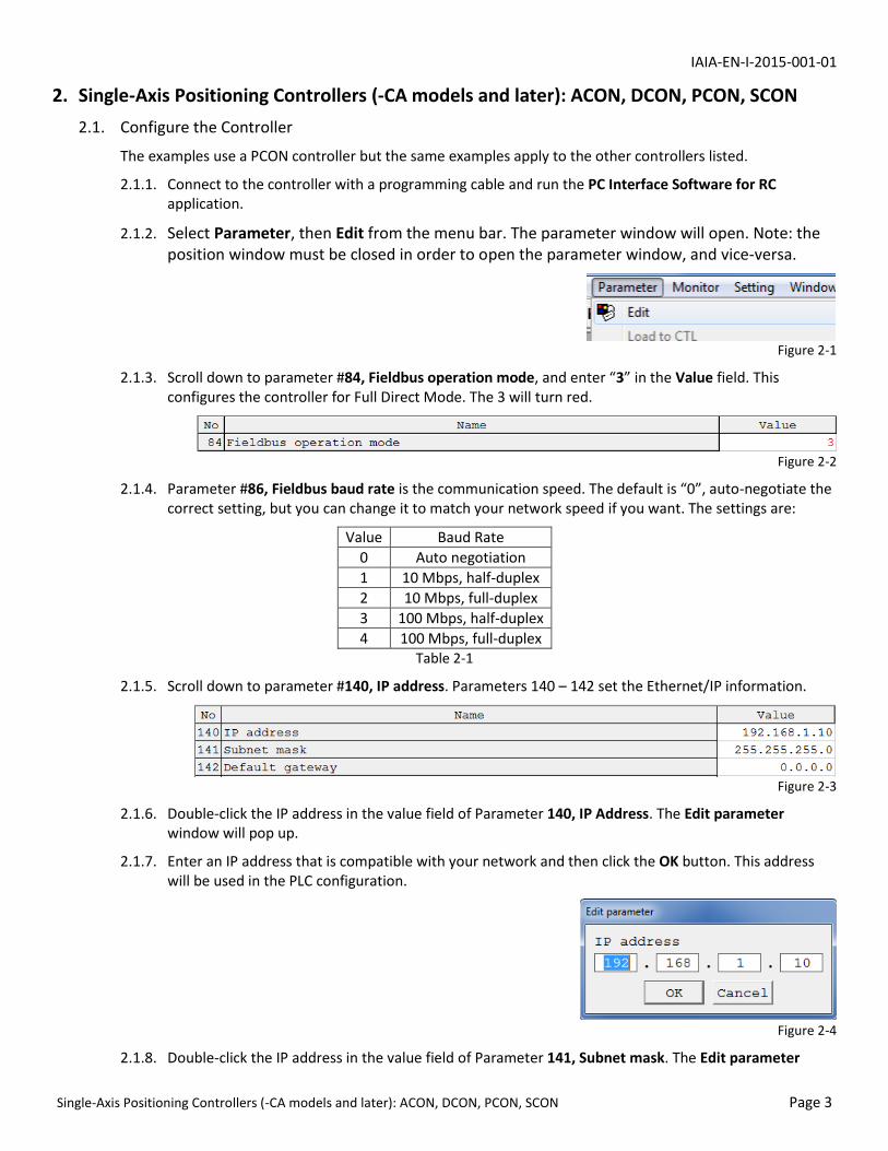
2.1.2. Select Parameter, then Edit from the menu bar. The parameter window will open. Note: the position window must be closed in order to open the parameter window, and vice-versa.
Figure 2-1
2.1.3. Scroll down to parameter #84, Fieldbus operation mode, and enter “3” in the Value field. This configures the controller for Full Direct Mode. The 3 will turn red.
Figure 2-2
2.1.4. Parameter #86, Fieldbus baud rate is the communication speed. The default is “0”, auto-negotiate the correct setting, but you can change it to match your network speed if you want. The settings are:
Value Baud Rate
0 Auto negotiation
1 10 Mbps, half-duplex
2 10 Mbps, full-duplex
3 100 Mbps, half-duplex
4 100 Mbps, full-duplex Table 2-1
2.1.5. Scroll down to parameter #140, IP address. Parameters 140 – 142 set the Ethernet/IP information.
Figure 2-3
2.1.6. Double-click the IP address in the value field of Parameter 140, IP Address. The Edit parameter window will pop up.
2.1.7. Enter an IP address that is compatible with your network and then click the OK button. This address will be used in the PLC configuration.
Figure 2-4
2.1.8. Double-click the IP address in the value field of Parameter 141, Subnet mask. The Edit parameter
IAIA-EN-I-2015-001-01
Single-Axis Positioning Controllers (-CA models and later): ACON, DCON, PCON, SCON Page 4
window will pop up.
Figure 2-5
2.1.9. Enter the appropriate subnet mask for your network and then click the OK button.
2.1.10. If a an Ethernet gateway device is being used between the PLC and controller, such as a router or smart switch that changes the IP addresses, double-click the IP address in the Parameter 142, Default gateway value field and enter its IP address using the same procedure as the previous steps. Most applications do not need to change this setting.
2.1.11. Click the Load to CTL button in the upper left corner of the Parameter window. The Confirmation window will pop up.
Figure 2-6
2.1.12. Click the Yes button and wait for the parameters to be written to the controller. The Confirmation window will pop up again.
Figure 2-7
2.1.13. Click the Yes button. The controller will perform a software restart to make the parameters active.
2.1.14. The PLC has control of the controller when the Manu/Auto switch is in the Auto position. In manual mode the RC software may be used to operate the controller & actuator.
2.2. Add the Controller to RSLogix.
2.2.1. Right-click the Ethernet network below the PLC’s Ethernet Port, in the I/O Configuration folder of the Controller Organizer, and then select New Module… (next figure).

IAIA-EN-I-2015-001-01
Single-Axis Positioning Controllers (-CA models and later): ACON, DCON, PCON, SCON Page 5
Figure 2-8
2.2.2. Select Communications in the Select Module pop-up window.
Figure 2-9
2.2.3. Navigate to Generic Ethernet Module and click the OK or Create button, depending on the version of RSLogix that you are using.
Figure 2-10
2.2.4. Fill in the parameters of the New Module window (next figure). Name can be any valid RSLogix name. IP Address should be an address that is appropriate for your network. Select Data – INT as the Comm Format; this and the Input, Output, and Configuration settings are critical.

IAIA-EN-I-2015-001-01
Single-Axis Positioning Controllers (-CA models and later): ACON, DCON, PCON, SCON Page 6
2.2.5. Uncheck the Open Module Properties checkbox; no additional parameters need to be set.
Figure 2-11
2.2.6. Click OK when done. The new module should be present in the Ethernet network, with the name that you entered, shown in the next figure.
Figure 2-12
2.2.7. RSLogix creates Controller Tag arrays for the module using the name that you entered. Tags for this example are shown in the next figure. Here, data from the controller is stored in the PCON:I array and data to the controller is in the PCON:O array.
Figure 2-13
2.3. Import the AOI’s and UDT’s
2.3.1. Download and extract the AOI files for the controller; the AOI files also contain the required UDT’s. If you decide not to use the AOI’s you can delete them & keep the UDT’s.

IAIA-EN-I-2015-001-01
Single-Axis Positioning Controllers (-CA models and later): ACON, DCON, PCON, SCON Page 7
2.3.2. Right-click Add-On Instructions in the Controller Organizer and select Import Add-On Instruction…
Figure 2-14
2.3.3. Navigate to the folder that contains the AOI files and select the moves AOI file (.L5X) for your controller, and then click the Import button.
Figure 2-15
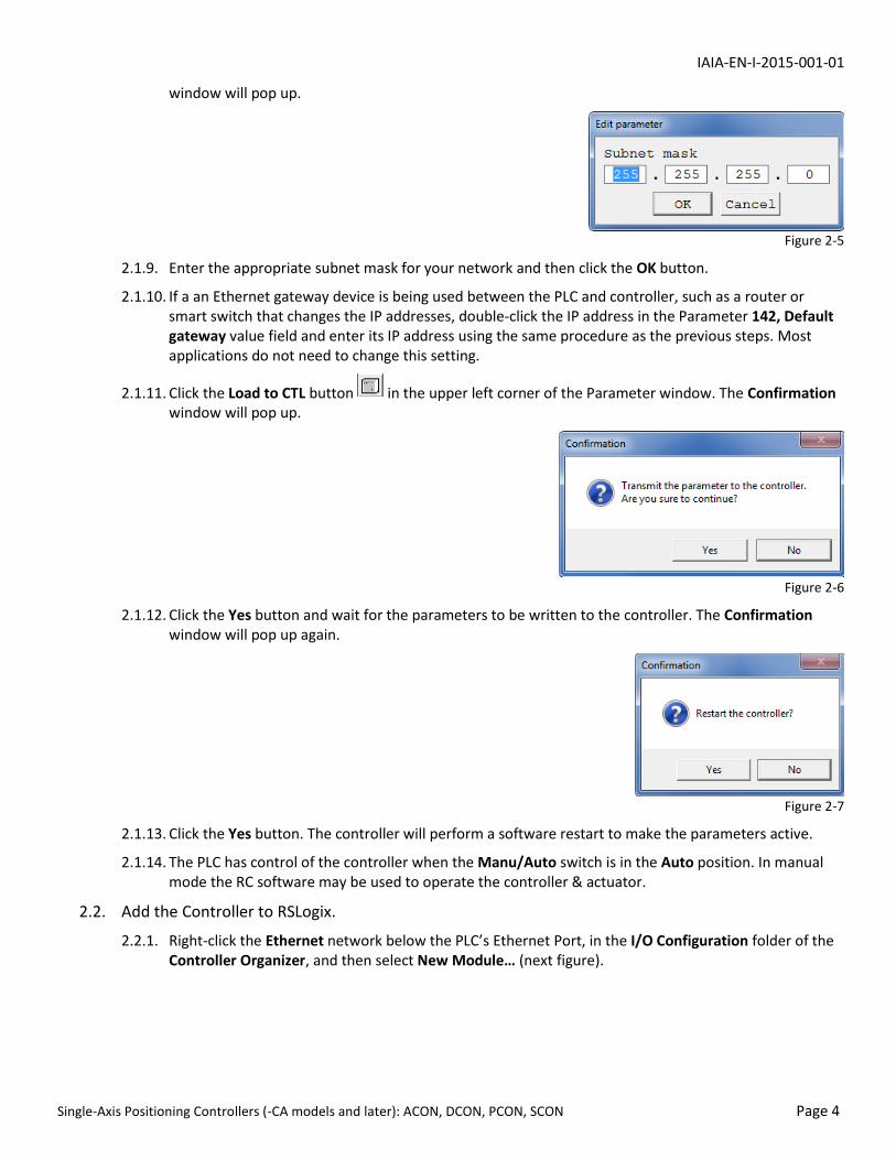
2.3.4. The Import Configuration window will open. Click the OK button to continue (next figure).
IAIA-EN-I-2015-001-01
Single-Axis Positioning Controllers (-CA models and later): ACON, DCON, PCON, SCON Page 8
Figure 2-16
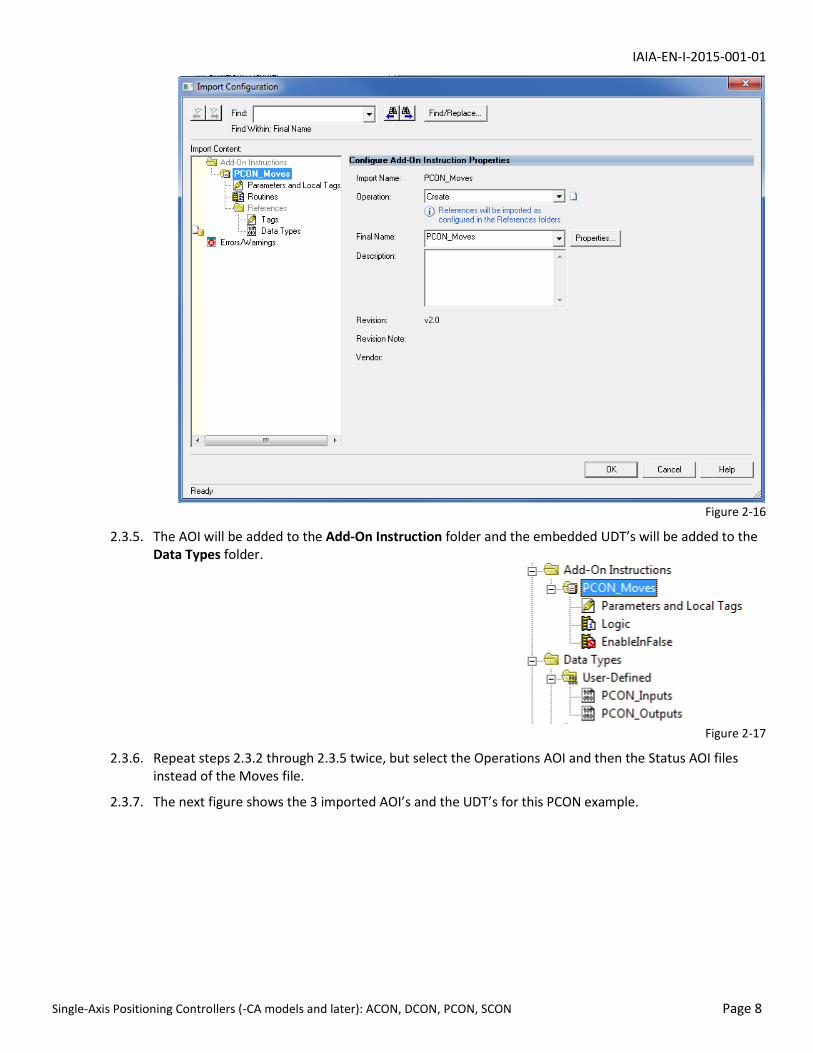
2.3.5. The AOI will be added to the Add-On Instruction folder and the embedded UDT’s will be added to the Data Types folder.
Figure 2-17
2.3.6. Repeat steps 2.3.2 through 2.3.5 twice, but select the Operations AOI and then the Status AOI files instead of the Moves file.
2.3.7. The next figure shows the 3 imported AOI’s and the UDT’s for this PCON example.

IAIA-EN-I-2015-001-01
Single-Axis Positioning Controllers (-CA models and later): ACON, DCON, PCON, SCON Page 9
Figure 2-18
2.3.8. The AOI’s also contain embedded data types for their internal use, which are added to the Data Types\ Add-On-Defined folder, shown here:
Figure 2-19
2.4. Create Tags to Utilize the UDT’s
2.4.1. Create input and output tag names that uniquely identify this axis or its function on your machine. For the Data Type, select the new UDT’s that were imported with the AOI’s. The next figure shows input and output tags for the PCON controller in this example. Their data types are the input & output UDT’s imported earlier.
Figure 2-20
2.4.2. Data from the controller needs to be transferred (mapped) from the generic Ethernet module input array to the newly-created input tag, PCON_In. This is done with a Synchronous Copy File (CPS) instruction.
Figure 2-21
PCON:I is a system defined tag that contains 16 integer words from the generic Ethernet module

IAIA-EN-I-2015-001-01
Single-Axis Positioning Controllers (-CA models and later): ACON, DCON, PCON, SCON Page 10
named PCON. The Dest tag of the instruction determines its Length. The Dest for this example is a single tag, PCON_In, so Length = 1. PCON_In contains members that require 16 integers worth of data so all 16 words from PCON:I get copied, even though the length is 1.
2.4.3. UDT members can be used individually or the entire contents of a UDT can be used by an AOI. A period (.) serves as a delimiter to specify an individual member of a UDT. In the next figure, PCON_In member Actual_Position is copied to a tag that is read by a Human Machine Interface (HMI).
Figure 2-22
2.4.4. Command data to the controller must be mapped from the PCON output UDT to the output tags of the generic Ethernet module, also accomplished by a CPS instruction. In our example, the AOI’s manipulate the members of UDT PCON_Out; that tag’s data is moved to output tag PCON:O, shown next.
Figure 2-23
2.4.5. AOI’s provide convenient methods to program a controller’s functions. They are inserted in ladder logic like any other instruction and they can be accessed at the bottom of the list in the Add Ladder Element popup window. Click the + symbol to expand Add-On and select the AOI that you want.
Figure 2-24
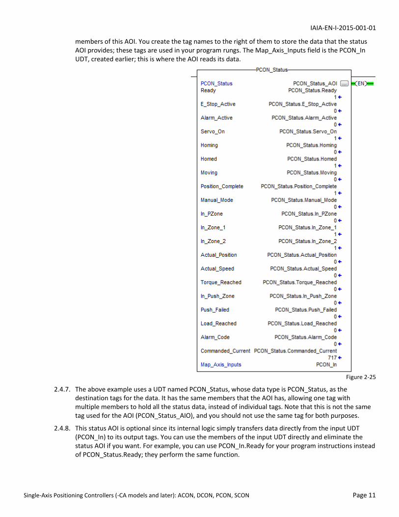
2.4.6. The Status AOI provides word and bit data from the controller. The AOI logic simply reads data from the generic Ethernet module and writes it to tags that you create. The next figure shows a Status AOI for our PCON example.
Tag PCON_Status_AOI is created to provide the AOI with a memory location to store & manipulate its internal data; its data type is PCON_Status. The tag names in black, on the left side of the AOI, are
IAIA-EN-I-2015-001-01
Single-Axis Positioning Controllers (-CA models and later): ACON, DCON, PCON, SCON Page 11
members of this AOI. You create the tag names to the right of them to store the data that the status AOI provides; these tags are used in your program rungs. The Map_Axis_Inputs field is the PCON_In UDT, created earlier; this is where the AOI reads its data.
Figure 2-25
2.4.7. The above example uses a UDT named PCON_Status, whose data type is PCON_Status, as the destination tags for the data. It has the same members that the AOI has, allowing one tag with multiple members to hold all the status data, instead of individual tags. Note that this is not the same tag used for the AOI (PCON_Status_AIO), and you should not use the same tag for both purposes.
2.4.8. This status AOI is optional since its internal logic simply transfers data directly from the input UDT (PCON_In) to its output tags. You can use the members of the input UDT directly and eliminate the status AOI if you want. For example, you can use PCON_In.Ready for your program instructions instead of PCON_Status.Ready; they perform the same function.
IAIA-EN-I-2015-001-01
Single-Axis Positioning Controllers (-CA models and later): ACON, DCON, PCON, SCON Page 12
Figure 2-26
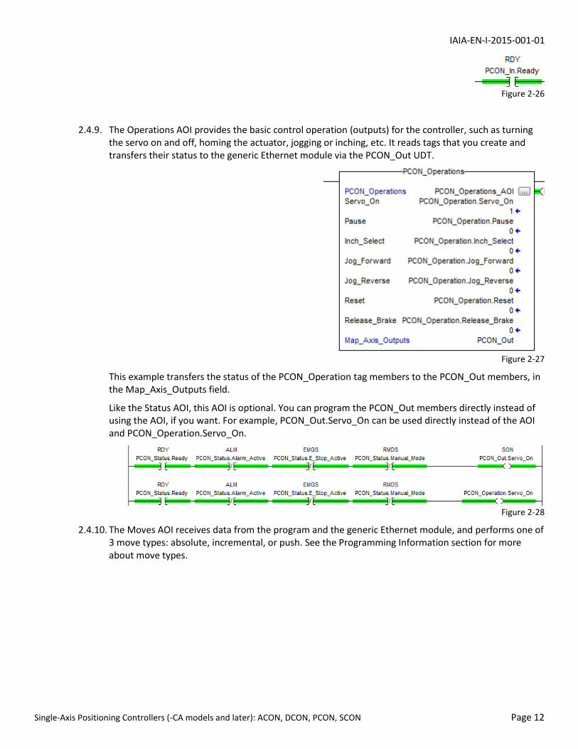
2.4.9. The Operations AOI provides the basic control operation (outputs) for the controller, such as turning the servo on and off, homing the actuator, jogging or inching, etc. It reads tags that you create and transfers their status to the generic Ethernet module via the PCON_Out UDT.
Figure 2-27
This example transfers the status of the PCON_Operation tag members to the PCON_Out members, in the Map_Axis_Outputs field.
Like the Status AOI, this AOI is optional. You can program the PCON_Out members directly instead of using the AOI, if you want. For example, PCON_Out.Servo_On can be used directly instead of the AOI and PCON_Operation.Servo_On.
Figure 2-28
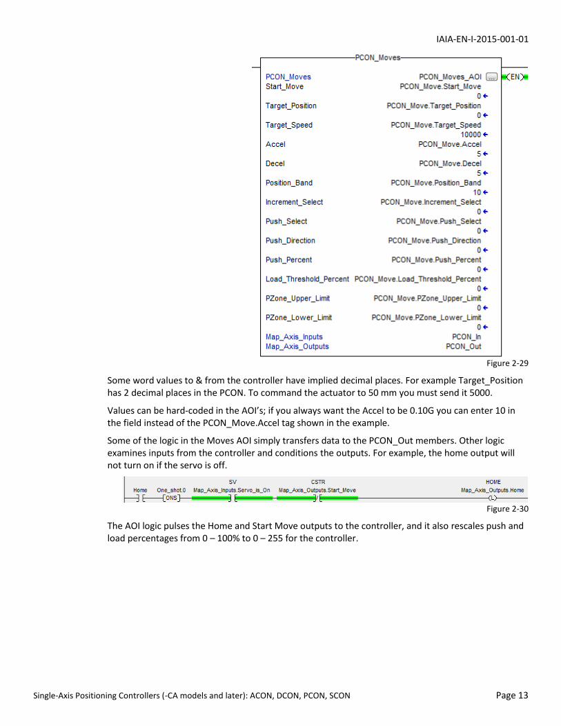
2.4.10. The Moves AOI receives data from the program and the generic Ethernet module, and performs one of 3 move types: absolute, incremental, or push. See the Programming Information section for more about move types.
IAIA-EN-I-2015-001-01
Single-Axis Positioning Controllers (-CA models and later): ACON, DCON, PCON, SCON Page 13
Figure 2-29
Some word values to & from the controller have implied decimal places. For example Target_Position has 2 decimal places in the PCON. To command the actuator to 50 mm you must send it 5000.
Values can be hard-coded in the AOI’s; if you always want the Accel to be 0.10G you can enter 10 in the field instead of the PCON_Move.Accel tag shown in the example.
Some of the logic in the Moves AOI simply transfers data to the PCON_Out members. Other logic examines inputs from the controller and conditions the outputs. For example, the home output will not turn on if the servo is off.
Figure 2-30
The AOI logic pulses the Home and Start Move outputs to the controller, and it also rescales push and load percentages from 0 – 100% to 0 – 255 for the controller.

IAIA-EN-I-2015-001-01
Controllers with Gateways, and Gateway Devices Page 14
2.4.11. The AOI’s contain the most commonly used UDT members. Depending on the controller model, a UDT may contain members not shown in any of the AOI’s. Double-click a UDT to open it and view its members and refer to the appropriate Ethernet/IP manual to see how the members can be used.
3. Controllers with Gateways, and Gateway Devices
Applies to: MSEP-C, MCON-C, MSCON, ERC3 Gateway, RCP6S Gateway, Robonet Gateway
MSEP, MCON, and MSCON controllers have integral gateways that exchange data between their built-in axes and a PLC or other Ethernet/IP master device. MSEP & MCON controllers have up to 8 axes; MSCON controllers have up to 6 axes.
ERC3 and RCP6S gateways do not have built-in axes; they exchange data between the PLC and actuators that have built-in controllers.
Robonet gateways are modules that connect to controllers using a bus system. They exchange data with the master device and the individual controllers.
In addition to axis data, the gateways send and exchange data for the gateway itself, so UDT’s are provided to handle this additional data. AOI’s are not needed for the gateway data because there is very little interaction needed.
The gateway input UDT’s have status bits for each axis and for the gateway in general. This data can be read from a UDT and used in the ladder logic directly. The gateway output UDT has a bit that must be turned on in order for the PLC to take control of the axes.
An MSCON has Direct Indication Mode and Direct Indication Mode 2. The AOI’s and UDT’s are written for Direct Indication Mode.
The figures are for an MCON controller but most apply to the other controllers and gateways. Differences are illustrated where appropriate.
3.1. Configure the Gateway.
3.1.1. Connect to the controller or gateway with a programming cable and run the Gateway Parameter Configuration Tool application.
3.1.2. Select the controller or gateway type in the pop-up window’s dropdown box and then click OK.
Figure 3-1
3.1.3. The Connection Check window will appear. Select the gateway unit number if different from 0 (the default) and then click OK.
Figure 3-2

IAIA-EN-I-2015-001-01
Controllers with Gateways, and Gateway Devices Page 15
3.1.4. The software will open. Click the Read button to read the existing parameters from the gateway.
Figure 3-3
3.1.5. Click Yes when the Confirmation window pops up. Ignore the text; it should say “Read the parameters from the Gateway unit?”
Figure 3-4
3.1.6. The tool will read the parameters and an Information window will pop up. Click OK.
Figure 3-5
The main window will populate with values read from the controller.
3.1.7. Select Setting and then EtherNet/IP Setting (I) from the menu:
Figure 3-6
3.1.8. Enter the IP address and Subnet mask for this controller. Enter a default gateway only if the PLC is on a different network and is connecting to the controller through a router or some other device that changes the IP address. Click OK when done.

IAIA-EN-I-2015-001-01
Controllers with Gateways, and Gateway Devices Page 16
Figure 3-7
3.1.9. Select Setting and then Specialty Parameter from the menu. In the GW-Param tab, set the unit velocity to 0.1 mm/s or 1.0 mm/s. All axes must use the same velocity units.
Figure 3-8
3.1.10. If you are connecting multiple controllers to this PLC select Setting and then Unit No. (U) from the menu to set this controller’s number. If this is the only multiple-axis controller connected to the PLC you do not need to change this setting.
Figure 3-9
3.1.11. For MSEP controllers:
Use the Axis Type dropdown box above the Full column to select the number of axes you are configuring on this controller. The axes must be selected in pairs because there can be two possible axes on each module of the controller. If a high-output MSEP module is used, it occupies the entire module.
In this example we will configure 3 axes so we select 4 in the dropdown. The Full fields for axes 0 through 3 should be populated with asterisks:
Figure 3-10
Change axis 3 from active to inactive by clicking in the cell with the asterisk. It will change from *
IAIA-EN-I-2015-001-01
Controllers with Gateways, and Gateway Devices Page 17
to (*). The parentheses indicate that it is not being used. The fields toggle each time they are clicked. This is how we would disable axis 3 if axis 2 were on a single-actuator, high-output module, or if we just don’t want to use that axis.
Figure 3-11
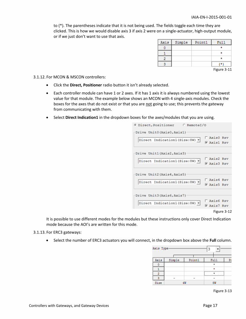
3.1.12. For MCON & MSCON controllers:
Click the Direct, Positioner radio button it isn’t already selected.
Each controller module can have 1 or 2 axes. If it has 1 axis it is always numbered using the lowest value for that module. The example below shows an MCON with 4 single-axis modules. Check the boxes for the axes that do not exist or that you are not going to use; this prevents the gateway from communicating with them.
Select Direct Indication1 in the dropdown boxes for the axes/modules that you are using.
Figure 3-12
It is possible to use different modes for the modules but these instructions only cover Direct Indication mode because the AOI’s are written for this mode.
3.1.13. For ERC3 gateways:
Select the number of ERC3 actuators you will connect, in the dropdown box above the Full column.
Figure 3-13

IAIA-EN-I-2015-001-01
Controllers with Gateways, and Gateway Devices Page 18
3.1.14. For RCP6S Gateways:
Select Direct Indication1 (Size: 8w) in the dropdown box.
Figure 3-14
Axis numbers and quantities depend on which gateway port an axis or hub is connected to. A hub connected to gateway port 0 may only be used for axis numbers 0 – 3. A single actuator connected to gateway port 0 must be axis 0.
A hub connected to gateway port 1 may only be used for axes 4 – 7. An actuator connected to gateway port 1 must be axis 4.
A hub connected to gateway port 2 may only be used for axes 8 – 11. An actuator connected to gateway port 2 must be axis 8.
A hub connected to gateway port 3 may only be used for axes 12 – 15. An actuator connected to gateway port 3 must be axis 12.
If you connected 4 actuators to the gateway (using no hubs), the axis numbers must be 0, 4, 8, and 12.
Unlike other gateways, the RCP6S gateway allows you to skip unused axes and optimize the exchanged data. For example if you are using axes 0 and 4, the gateway can place the axis 4 data after the axis 0 data, without sending data for axes 1, 2 and 3.
To enable the optimization (axis skip) feature:
1. Select Setting, Specialty Parameter from the menu.
Figure 3-15
2. Click the GWmode Select tab.
Figure 3-16
3. Select valid (without Alarm) for Fieldbus I/O Area Optimization Setting.
Figure 3-17
Use the Axis Type dropdown box (it should say number of axes) to select how many axes that you will configure. You may have to select more axes than you have and then “skip” the ones you are not using (see the explanation above and the examples below).
Example 1: assume there are 4 actuators connected directly to the gateway (no hubs) so they must be numbered 0, 4, 8, and 12. Sixteen axes are selected, as if 4 hubs were connected, and the

IAIA-EN-I-2015-001-01
Controllers with Gateways, and Gateway Devices Page 19
unused axes are skipped.
Figure 3-18
The gateway will compress the 16 bytes of data for each used axis into 64 bytes instead of reserving 16 bytes for each unconnected axis. The data exchanged with the PLC will be 16 bytes for the gateway and 16 bytes per axis, or 80 bytes total.
Figure 3-19
Example 2: assume there are hubs connected to gateway ports 0 and 1 and each hub has 3 actuators connected to it. The hub on port 0 will be axes 0, 1, and 2. Axis 3 is skipped.
The first actuator for gateway port 1 must begin with 4. The actuators on this hub are axes axes 4, 5, and 6. Axis 7 is skipped.
The number of bytes exchanged is 16 for the gateway plus 16 per axis, or 16 + (6 * 16) = 112 bytes.
Figure 3-20

IAIA-EN-I-2015-001-01
Controllers with Gateways, and Gateway Devices Page 20
Figure 3-21
3.1.15. For Robonet Gateways:
Select the number of axes in the dropdown box above the Full column (maximum = 8). In Full Direct mode only even-numbered axes can be used. The example shown here has 4 axes selected: 0, 2, 4, and 6.
3.1.16. When you have the axes configured click the Write button. The tool will write the parameters to the controller and an Information window will pop up. Click OK to close it.
Figure 3-22

IAIA-EN-I-2015-001-01
Controllers with Gateways, and Gateway Devices Page 21
3.1.17. A Confirmation window will pop up. Ignore the text; it is asking if it is ok to restart the controller. Click Yes.
Figure 3-23
3.1.18. Another Confirmation window will pop up. Ignore the text; it is asking if it is ok to read the parameters from the controller. Click Yes.
Figure 3-24
3.1.19. Yet another Information window will pop up. Click OK to close it.
Figure 3-25
3.1.20. The window shown next will pop up, listing the operation modes available for this controller. This is information, not an error message. Click OK to close it.
Figure 3-26
IAIA-EN-I-2015-001-01
Controllers with Gateways, and Gateway Devices Page 22
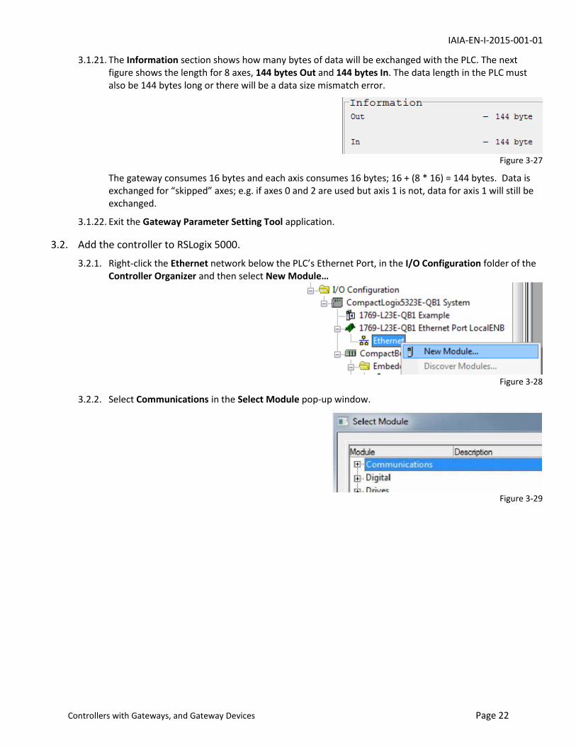
3.1.21. The Information section shows how many bytes of data will be exchanged with the PLC. The next figure shows the length for 8 axes, 144 bytes Out and 144 bytes In. The data length in the PLC must also be 144 bytes long or there will be a data size mismatch error.
Figure 3-27
The gateway consumes 16 bytes and each axis consumes 16 bytes; 16 + (8 * 16) = 144 bytes. Data is exchanged for “skipped” axes; e.g. if axes 0 and 2 are used but axis 1 is not, data for axis 1 will still be exchanged.
3.1.22. Exit the Gateway Parameter Setting Tool application.
3.2. Add the controller to RSLogix 5000.
3.2.1. Right-click the Ethernet network below the PLC’s Ethernet Port, in the I/O Configuration folder of the Controller Organizer and then select New Module…
Figure 3-28
3.2.2. Select Communications in the Select Module pop-up window.
Figure 3-29
IAIA-EN-I-2015-001-01
Controllers with Gateways, and Gateway Devices Page 23
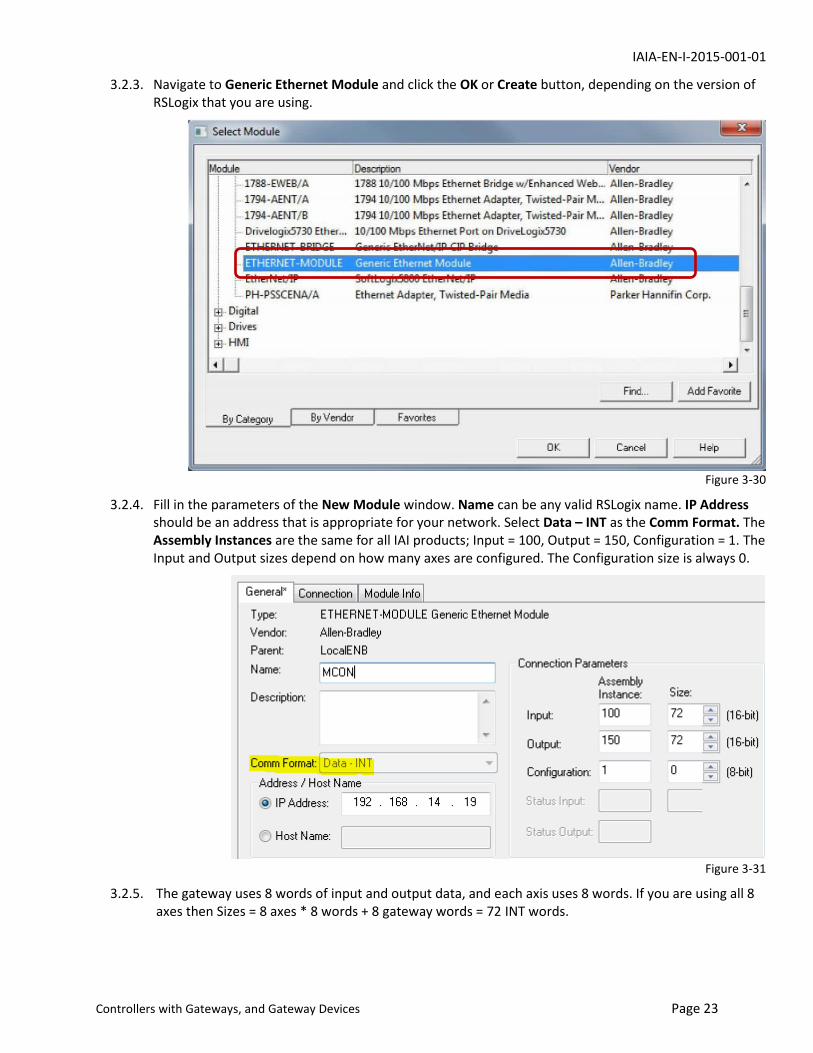
3.2.3. Navigate to Generic Ethernet Module and click the OK or Create button, depending on the version of RSLogix that you are using.
Figure 3-30
3.2.4. Fill in the parameters of the New Module window. Name can be any valid RSLogix name. IP Address should be an address that is appropriate for your network. Select Data – INT as the Comm Format. The Assembly Instances are the same for all IAI products; Input = 100, Output = 150, Configuration = 1. The Input and Output sizes depend on how many axes are configured. The Configuration size is always 0.
Figure 3-31
3.2.5. The gateway uses 8 words of input and output data, and each axis uses 8 words. If you are using all 8 axes then Sizes = 8 axes * 8 words + 8 gateway words = 72 INT words.

IAIA-EN-I-2015-001-01
Controllers with Gateways, and Gateway Devices Page 24
The table at right shows the Size value for the number of configured axes; input and output sizes are always equal.
3.2.6. Uncheck the Open Module Properties checkbox if it is checked; no additional parameters need to be set.
3.2.7. Click OK when done. The new module should be present in the Ethernet network, with the name that you entered.
Figure 3-32
3.2.8. The PLC software creates Controller Tag arrays for the module using the name that you entered. Tags for this example are shown in the next figure. Data from the controller is stored in the MCON:I array and data to the controller is in the MCON:O array.
Figure 3-33
3.3. Import the Axis AOI’s
3.3.1. Download and extract the AOI files for the axes and the UDT files for the MCON gateway. The axis AOI files also contain the axis UDT’s; they will be imported with the AOI’s.
3.3.2. Right-click Add-On Instructions in the Controller Organizer and select Import Add-On Instruction…
Figure 3-34
3.3.3. Navigate to the folder that contains the AOI files and select the Moves AOI file (.L5X) for your controller and then click the Import button.
Figure 3-35
3.3.4. The Import Configuration window will open. Click the OK button to continue (next figure).
# of Axes Size
1 16
2 24
3 32
4 40
5 48
6 56
7 64
8 72
IAIA-EN-I-2015-001-01
Controllers with Gateways, and Gateway Devices Page 25
Figure 3-36
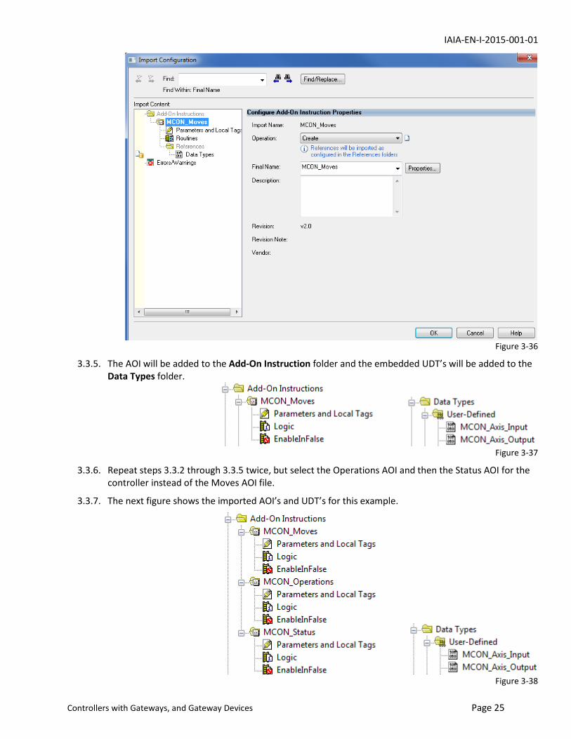
3.3.5. The AOI will be added to the Add-On Instruction folder and the embedded UDT’s will be added to the Data Types folder.
Figure 3-37
3.3.6. Repeat steps 3.3.2 through 3.3.5 twice, but select the Operations AOI and then the Status AOI for the controller instead of the Moves AOI file.
3.3.7. The next figure shows the imported AOI’s and UDT’s for this example.
Figure 3-38
IAIA-EN-I-2015-001-01
Controllers with Gateways, and Gateway Devices Page 26
3.4. Import the Gateway UDT’s
3.4.1. Right click the Data Types\User-Defined folder in the Controller Organizer and click Import Data Type…
Figure 3-39
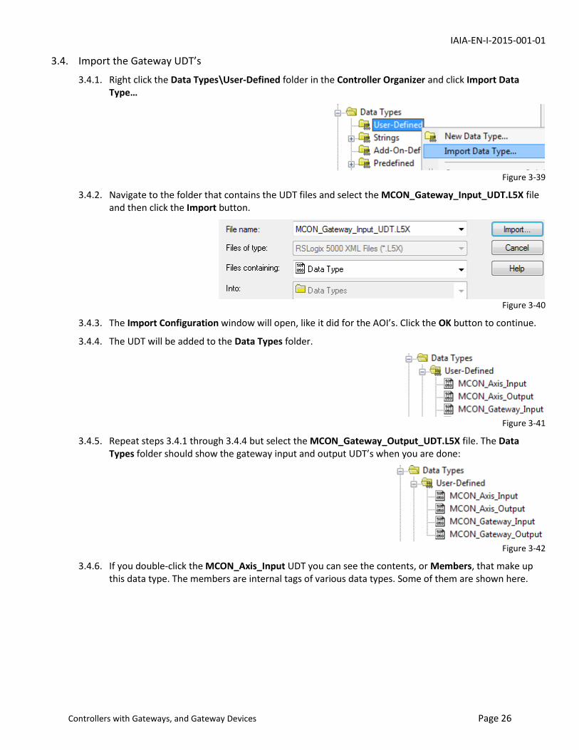
3.4.2. Navigate to the folder that contains the UDT files and select the MCON_Gateway_Input_UDT.L5X file and then click the Import button.
Figure 3-40
3.4.3. The Import Configuration window will open, like it did for the AOI’s. Click the OK button to continue.
3.4.4. The UDT will be added to the Data Types folder.
Figure 3-41
3.4.5. Repeat steps 3.4.1 through 3.4.4 but select the MCON_Gateway_Output_UDT.L5X file. The Data Types folder should show the gateway input and output UDT’s when you are done:
Figure 3-42
3.4.6. If you double-click the MCON_Axis_Input UDT you can see the contents, or Members, that make up this data type. The members are internal tags of various data types. Some of them are shown here.

IAIA-EN-I-2015-001-01
Controllers with Gateways, and Gateway Devices Page 27
Figure 3-43
3.5. Create Tags to Use the UDT’s and AOI’s
3.5.1. Create input and output tags for the Gateway inputs and outputs. The data types will be MCON_Gateway_Input and MCON_Gateway_Output, respectively. These tags are used in Synchronous Copy File (CPS) instructions to transfer data from and to the controller. MCON examples are shown here.
Figure 3-44
The Destination tag of an instruction determines its Length. UDT MCON_Inputs_GW is a single tag so Length = 1 on the first CPS above. The processor copies data starting at MCON:I:Data[0], until the tag is filled, which takes 8 integer words (0 – 7).
Destination MCON_O:Data[0] is an array of integer words and source MCON_Outputs_GW contains 8 integer words of data, so Length = 8 for the second CPS above.
3.5.2. Create input and output tags that uniquely identify each axis of the MCON. For the Data Types, select the MCON_Axis_Input and MCON_Axis_Output UDT’s that were imported with the AOI’s. You can create a tag for each axis or use an array of tags.
Each axis uses 8 integer words of the “raw” data arrays from and to the controller. The example below shows instructions that copy data from 3 axes of the controller to 3 UDT’s. Each UDT requires 8 integer words from the raw data. The Gateway uses words 0 to 7, axis 0 uses words 8 to 15, axis 1 uses words 16 to 23, etc. This figure shows the MCON axis data being used in an array of UDT’s.
Figure 3-45
Below are the corresponding output instructions for the 3 axes shown above.

IAIA-EN-I-2015-001-01
Controllers with Gateways, and Gateway Devices Page 28
Figure 3-46
3.5.3. The next figure shows an example that uses individual axis tags instead of an array.
Figure 3-47
3.5.4. The members of a UDT can be used individually or the entire contents of the tag can be used by an AOI. A period (.) is used as a delimiter to specify a member of a UDT. In the next figure, MCON_Inputs_Axis[0] member Actual_ Position is copied to a tag that is read by a Human Machine Interface (HMI).
Figure 3-48
3.5.5. AOI’s provide convenient methods to program the controller functions. They are inserted in ladder logic like any other instruction; they are located at the bottom of the list in the Add Ladder Element popup window. Click the + symbol to expand Add-On and select the AOI that you want.
Figure 3-49
3.5.6. The Status AOI provides word and bit data from the controller. The AOI logic simply reads data from the generic Ethernet module and writes it to tags that you create. The next figure shows a Status AOI for this MCON example.
Tag MCON_Status_Axis[0] is created to provide the AOI with a memory location to store & manipulate its internal data; its data type is MCON_Status. The tag names in black, on the left side of the AOI, are members of this AOI. You create the tag names to the right of them to store the data that the status AOI provides; these tags are used in your program rungs. The Map_Axis_Inputs field is the MCON input

IAIA-EN-I-2015-001-01
Controllers with Gateways, and Gateway Devices Page 29
UDT for this axis, created earlier; this is where the AOI gets its data.
Figure 3-50
3.5.7. The destination tags in this example are word arrays with 8 elements or bits of SINT words. Each array provides 8 words and the subscript corresponds to the axis number. Each bit of a SINT corresponds to the axis number. This makes it easy to copy code from one routine to another and do a search & replace to change the tags.
3.5.8. This status AOI is optional since its internal logic simply transfers data directly from the input UDT (MCON_Status_Axis[0]) to its destination tags. You can use the members of the input UDT directly and eliminate the status AOI if you want. For example, you can use MCON_Status_Axis[0]).Ready for your program instructions instead of Status_Ready.0; they perform the same function.
Figure 3-51

IAIA-EN-I-2015-001-01
Controllers with Gateways, and Gateway Devices Page 30
3.5.9. The Operations AOI provides the basic control operation (outputs) for the controller, such as turning the servo on and off, homing the actuator, jogging or inching, etc. It reads tags that you create and transfers their status to the generic Ethernet module via the MCON_Axis_Out[0]UDT.
Figure 3-52
Like the Status AOI, this AOI is optional. You can program the MCON_Axis_Out[0] members directly instead of using the AOI, if you want. For example, MCON_Axis_Out[0].Servo_On can be used directly instead of the AOI and Servo_On.0.
Figure 3-53
3.5.10. The Moves AOI receives data from the ladder program and the generic Ethernet module, and performs one of 3 move types: absolute, incremental, or push. See the Programming Information section for more about move types.
Figure 3-54
IAIA-EN-I-2015-001-01
Programming Information Page 31
Some word values to & from the controller have implied decimal places. For example Target_Position has 2 decimal places in the MCON. To command the actuator to 50 mm you must send it 5000.
The decimal places for the target speed depend on the units chosen in the Gateway Parameter Configuration Tool earlier. They will either be in mm/second or 0.1 mm/second.
Values can be hard-coded in the AOI’s; if you always want the acceleration and deceleration to be 0.10G you can enter 10 in the field instead of the Accel_Decel[0]tag shown above.
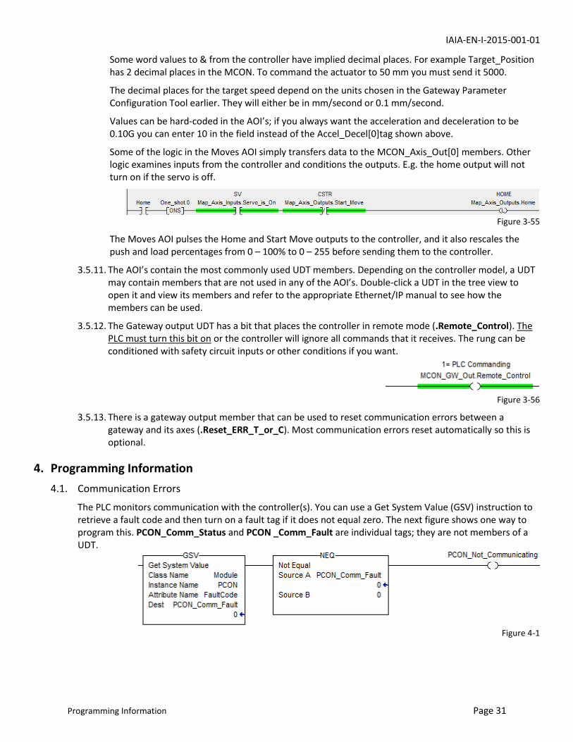
Some of the logic in the Moves AOI simply transfers data to the MCON_Axis_Out[0] members. Other logic examines inputs from the controller and conditions the outputs. E.g. the home output will not turn on if the servo is off.
Figure 3-55
The Moves AOI pulses the Home and Start Move outputs to the controller, and it also rescales the push and load percentages from 0 – 100% to 0 – 255 before sending them to the controller.
3.5.11. The AOI’s contain the most commonly used UDT members. Depending on the controller model, a UDT may contain members that are not used in any of the AOI’s. Double-click a UDT in the tree view to open it and view its members and refer to the appropriate Ethernet/IP manual to see how the members can be used.
3.5.12. The Gateway output UDT has a bit that places the controller in remote mode (.Remote_Control). The PLC must turn this bit on or the controller will ignore all commands that it receives. The rung can be conditioned with safety circuit inputs or other conditions if you want.
Figure 3-56
3.5.13. There is a gateway output member that can be used to reset communication errors between a gateway and its axes (.Reset_ERR_T_or_C). Most communication errors reset automatically so this is optional.
4. Programming Information
4.1. Communication Errors
The PLC monitors communication with the controller(s). You can use a Get System Value (GSV) instruction to retrieve a fault code and then turn on a fault tag if it does not equal zero. The next figure shows one way to program this. PCON_Comm_Status and PCON _Comm_Fault are individual tags; they are not members of a UDT.
Figure 4-1

IAIA-EN-I-2015-001-01
Programming Information Page 32
4.2. Using the AOI’s and UDT’s
4.2.1. CPS instructions for the input UDT’s should be located before the ladder logic that uses the input data and the CPS that writes to the outputs should be located after the logic. The general rule is: read the inputs, execute the logic, and then write the outputs.
4.2.2. Alarm codes are read in decimal but the IAI manuals list them in hexadecimal so you must convert them.
4.2.3. An alarm code of 163 (0A3 hexadecimal) means the controller received an out-of-range value in one of the move data.
These values must always be greater than zero: speed, acceleration, deceleration, and position band.
Target position can be a negative number but only if an incremental move is selected, or you have a rotary actuator that isn’t in index mode.
To find the valid range of a motion value, log onto the controller with the Robo Cylinder software. Open the position edit window and click on a cell in the column you want to know about. The valid range will be displayed at the bottom of the window.
CON-type controller speeds are in units of 0.01 mm/sec. Speeds for multiple-axis controllers and gateways are in units of 0.1 or 1 mm/sec, as selected by the Parameter Configuration Tool (Setting, Specialty Parameter in the menu).
4.2.4. If a start move bit (CSTR or DSTR) is held on, the controller will not turn on the position complete bit (PEND).
4.2.5. You don’t need to load the position and other move values prior to turning on the start move bit. They can be sent to the controller in the same scan.
4.2.6. The pause bit (STP) stops the actuator while the bit is on. The actuator resumes its motion when the bit is turned off.
4.2.7. To cancel a move in progress, turn on the pause and reset bits.
4.2.8. A move command will replace a move in progress. If the actuator is at 50 mm, moving to 70 mm, and you command it to 30 mm, it will immediately abort the previous command and move to 30 mm. In this example it will stop at the commanded deceleration rate and move at the commanded acceleration rate & speed in the opposite direction.
4.2.9. Position band determines when the controller turns on the position complete bit. The actuator does not stop when it enters this band. Widening the band just turns on the position complete bit earlier.
For example if the target position is 50 mm and position band is 5 mm, position complete will turn on at 45 mm when moving in a positive direction, or 55 mm when moving in a negative direction. The actuator will continue to the 50 mm target position.
This feature can be useful if you need to know when the actuator is close enough to the target position to start another axis or to perform some other function on the machine, to reduce cycle time.
4.2.10. The Servo_On bit is not momentary; it must be held on to keep the servo turned on.
4.2.11. Move types
a. Absolute moves command the actuator to a specific point along its stroke such as 45.67 mm.
b. Incremental moves command the actuator to move a specific distance from its actual position. If the actuator is at 50 mm and is given an incremental move of -20 mm it will move to 30 mm.
c. Push moves limit the motor current and allow the actuator to push against an object and stall out without causing an overload condition, emulating the operation of an air cylinder. There are two
IAIA-EN-I-2015-001-01
Programming Information Page 33
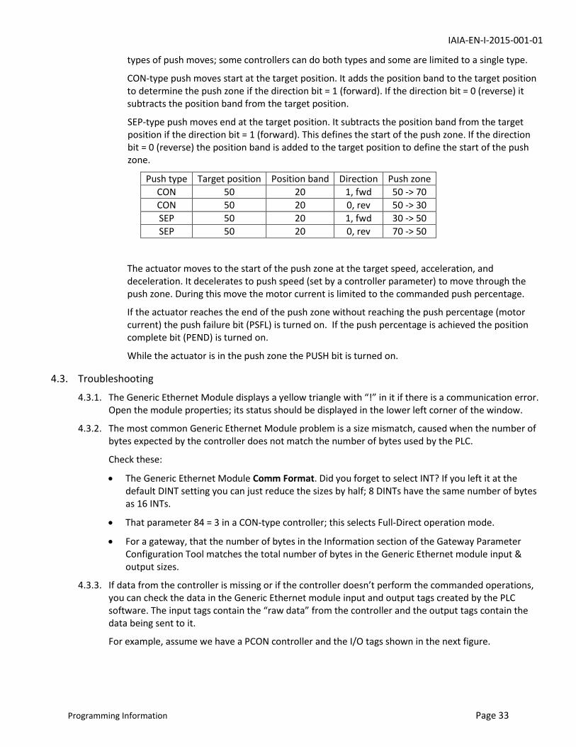
types of push moves; some controllers can do both types and some are limited to a single type.
CON-type push moves start at the target position. It adds the position band to the target position to determine the push zone if the direction bit = 1 (forward). If the direction bit = 0 (reverse) it subtracts the position band from the target position.
SEP-type push moves end at the target position. It subtracts the position band from the target position if the direction bit = 1 (forward). This defines the start of the push zone. If the direction bit = 0 (reverse) the position band is added to the target position to define the start of the push zone.
Push type Target position Position band Direction Push zone
CON 50 20 1, fwd 50 -> 70
CON 50 20 0, rev 50 -> 30
SEP 50 20 1, fwd 30 -> 50
SEP 50 20 0, rev 70 -> 50
The actuator moves to the start of the push zone at the target speed, acceleration, and deceleration. It decelerates to push speed (set by a controller parameter) to move through the push zone. During this move the motor current is limited to the commanded push percentage.
If the actuator reaches the end of the push zone without reaching the push percentage (motor current) the push failure bit (PSFL) is turned on. If the push percentage is achieved the position complete bit (PEND) is turned on.
While the actuator is in the push zone the PUSH bit is turned on.
4.3. Troubleshooting
4.3.1. The Generic Ethernet Module displays a yellow triangle with “!” in it if there is a communication error. Open the module properties; its status should be displayed in the lower left corner of the window.
4.3.2. The most common Generic Ethernet Module problem is a size mismatch, caused when the number of bytes expected by the controller does not match the number of bytes used by the PLC.
Check these:
The Generic Ethernet Module Comm Format. Did you forget to select INT? If you left it at the default DINT setting you can just reduce the sizes by half; 8 DINTs have the same number of bytes as 16 INTs.
That parameter 84 = 3 in a CON-type controller; this selects Full-Direct operation mode.
For a gateway, that the number of bytes in the Information section of the Gateway Parameter Configuration Tool matches the total number of bytes in the Generic Ethernet module input & output sizes.
4.3.3. If data from the controller is missing or if the controller doesn’t perform the commanded operations, you can check the data in the Generic Ethernet module input and output tags created by the PLC software. The input tags contain the “raw data” from the controller and the output tags contain the data being sent to it.
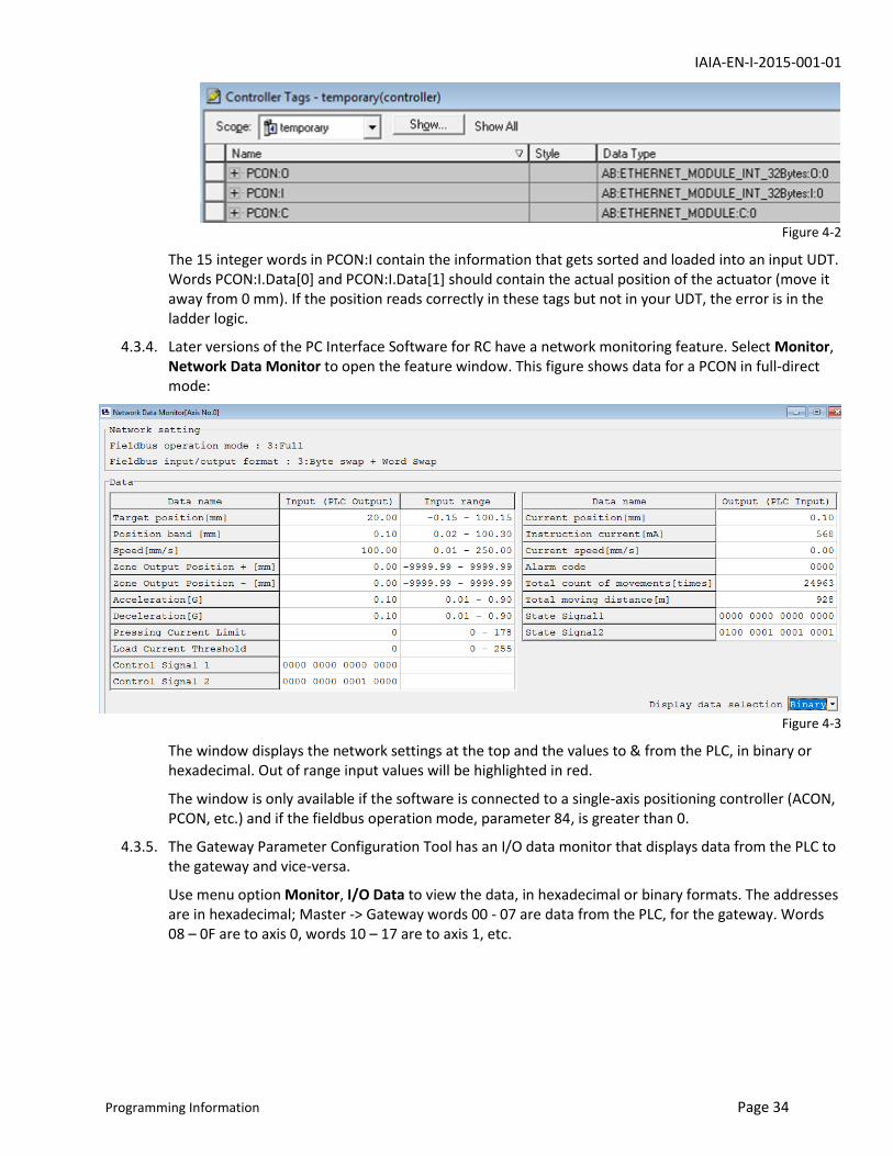
For example, assume we have a PCON controller and the I/O tags shown in the next figure.
IAIA-EN-I-2015-001-01
Programming Information Page 34
Figure 4-2
The 15 integer words in PCON:I contain the information that gets sorted and loaded into an input UDT. Words PCON:I.Data[0] and PCON:I.Data[1] should contain the actual position of the actuator (move it away from 0 mm). If the position reads correctly in these tags but not in your UDT, the error is in the ladder logic.
4.3.4. Later versions of the PC Interface Software for RC have a network monitoring feature. Select Monitor, Network Data Monitor to open the feature window. This figure shows data for a PCON in full-direct mode:
Figure 4-3
The window displays the network settings at the top and the values to & from the PLC, in binary or hexadecimal. Out of range input values will be highlighted in red.
The window is only available if the software is connected to a single-axis positioning controller (ACON, PCON, etc.) and if the fieldbus operation mode, parameter 84, is greater than 0.
4.3.5. The Gateway Parameter Configuration Tool has an I/O data monitor that displays data from the PLC to the gateway and vice-versa.
Use menu option Monitor, I/O Data to view the data, in hexadecimal or binary formats. The addresses are in hexadecimal; Master -> Gateway words 00 - 07 are data from the PLC, for the gateway. Words 08 – 0F are to axis 0, words 10 – 17 are to axis 1, etc.

IAIA-EN-I-2015-001-01
Programming Information Page 35
Figure 4-4