Embed Size (px)
Citation preview

Engineered Products for Robotic ProductivityPinnacle Park • 1031 Goodworth Drive • Apex, NC 27539 USA • Tel: +1.919.772.0115 • Fax: +1.919.772.8259 • www.ati-ia.com • Email: [email protected]
Manual
EtherCAT F/T Interface
Document #: 9620-05-EtherCAT

Manual, EtherCAT F/T Interface Document #9620-05-EtherCAT-03
Pinnacle Park • 1031 Goodworth Drive • Apex, NC 27539 USA • Tel: +1.919.772.0115 • Fax: +1.919.772.8259 • www.ati-ia.com • Email: [email protected] 2
ForewordInformation contained in this document is the property of ATI Industrial Automation, Inc. and shall not be reproduced in whole or in part without prior written approval of ATI Industrial Automation, Inc. The information herein is subject to change without notice and should not be construed as a commitment of ATI Industrial Automation, Inc. This manual is periodically revised to reflect and incorporate changes made to the F/T system.
ATI Industrial Automation, Inc. assumes no responsibility for any errors or omissions in this document.
Copyright © by ATI Industrial Automation, Inc., Apex, North Carolina USA. All Rights Reserved. Published in the USA.
In consideration that ATI Industrial Automation, Inc. (ATI) products are intended for use with robotic and/or automated machines, ATI does not recommend the use of its products for applications wherein failure or malfunction of an ATI component or system threatens life or makes injury probable. Anyone who uses or incorporates ATI components within any potentially life-threatening system must obtain ATI’s prior consent based upon assurance to ATI that a malfunction of ATI’s component does not pose direct or indirect threat of injury or death, and (even if such consent is given) shall indemnify ATI from any claim, loss, liability, and related expenses arising from any injury or death resulting from use of ATI components.
All trademarks belong to their respective owners.
Windows™ is a registered trademark of Microsoft Corporation.
Note
Please read the manual before calling customer service. Before calling, have the following information available:
1. Serial number (e.g., FT01234)
2. Transducer model (e.g., Nano17, Gamma, Theta, etc.)
3. Calibration (e.g., US-15-50, SI-65-6, etc.)
4. Accurate and complete description of the question or problem
5. Computer and software information. Operating system, PC type, drivers, application software, and other relevant information about your configuration.
If possible, be near the F/T system when calling.
How to Reach Us
Sale, Service and Information about ATI products:
ATI Industrial Automation 1031 Goodworth Drive Apex, NC 27539 USA www.ati-ia.com Tel: +1.919.772.0115 Fax: +1.919.772.8259 E-mail: [email protected]
Technical support and questions:Application Engineering Tel: +1.919.772.0115, Option 2, Option 2 Fax: +1.919.772.8259 E-mail: [email protected]

Manual, EtherCAT F/T Interface Document #9620-05-EtherCAT-03
Pinnacle Park • 1031 Goodworth Drive • Apex, NC 27539 USA • Tel: +1.919.772.0115 • Fax: +1.919.772.8259 • www.ati-ia.com • Email: [email protected] 3
Table of Contents1. Safety ......................................................................................................................................... 6
1.1 ExplanationofNotifications ......................................................................................................... 6
1.2 General Safety Guidelines ............................................................................................................ 6
1.3 Safety Precautions ........................................................................................................................ 6
2. Product Overview ..................................................................................................................... 72.1 LED Functions ............................................................................................................................... 7
2.1.1 EtherCAT Link/Activity LED ................................................................................................ 7
2.1.2 Run LED ............................................................................................................................. 8
2.1.3 Sensor status LED ............................................................................................................. 8
3. Installation ................................................................................................................................ 93.1 Providing Power to the EtherCAT Sensor ................................................................................... 9
3.1.1 Providing Power Using PoE ............................................................................................... 9
3.1.2 Providing Power Using Extenal Power ............................................................................. 10
3.2 EtherCAT Connector 4-Pin M12 ................................................................................................. 10
3.3 Optional Power Connector 3-Pin M8 ......................................................................................... 11
3.4 Optional Earth Ground Connection ........................................................................................... 11
4. Operation ................................................................................................................................ 124.1 Sample Rate ................................................................................................................................. 12
4.2 Filtering ........................................................................................................................................ 12
4.3 Threshold Monitoring ................................................................................................................. 12
4.4 Tool Transformation .................................................................................................................... 12
5. EtherCAT Bus Interface ......................................................................................................... 145.1 PDO Interface ............................................................................................................................... 14
5.2 EtherCAT Dictionary Objects (SDO Data) ................................................................................ 145.2.1 Object 0x2020: Tool Transformation ................................................................................. 14
5.2.2 Object 0x2040: Calibration ............................................................................................... 15
5.2.3 Object 0x2060: Monitor Condition .................................................................................... 17
5.2.4 Object 0x2080: Diagnostic Readings ............................................................................... 17
5.2.5 Object 0x2090: Version .................................................................................................... 18
5.2.6 Object 0x6000: Reading Data .......................................................................................... 18
5.2.7 Object 0x6010: Status Code ............................................................................................ 19
5.2.8 Object 0x6020: Sample Counter ...................................................................................... 20
5.2.9 Object 0x7010: Control Codes ......................................................................................... 20
6. Troubleshooting ..................................................................................................................... 216.1 Errors with Force and Torque Readings ................................................................................... 21
Manual, EtherCAT F/T Interface Document #9620-05-EtherCAT-03
Pinnacle Park • 1031 Goodworth Drive • Apex, NC 27539 USA • Tel: +1.919.772.0115 • Fax: +1.919.772.8259 • www.ati-ia.com • Email: [email protected] 4
7. Specifications ......................................................................................................................... 227.1 Storage and Operating Conditions ............................................................................................ 22
7.2 ElectricalSpecifications ............................................................................................................. 22
7.3 Weights and Dimensions ............................................................................................................ 22
8. Drawings ................................................................................................................................. 239. Terms and Conditions of Sale ............................................................................................... 25

Manual, EtherCAT F/T Interface Document #9620-05-EtherCAT-03
Pinnacle Park • 1031 Goodworth Drive • Apex, NC 27539 USA • Tel: +1.919.772.0115 • Fax: +1.919.772.8259 • www.ati-ia.com • Email: [email protected] 5
Glossary of TermsTerm Definition
CoE CANopen over EtherCAT, the preferred embedded protocol for configuring EtherCAT devices. Used within SDO to encode the configuration data.
DINT A data type representing an unsigned integer with 32 bits.
EtherCAT An industrial automation fieldbus.
FoE File access over EtherCAT, the preferred embedded protocol for uploading new firmware to EtherCAT devices.
F/T Force/Torque.
F/T Transducer Converts force and torque into an electrical signal.
MAP The Mounting Adapter Plate (MAP) is the transducer plate that attaches to the fixed surface or robot arm.
PDO Process Data Object, a protocol for reading and writing real-time process information cyclically.
PoE Power-over-Ethernet, is a method of delivering electrical power to a PoE-compatible Ethernet device through the Ethernet cable. This simplifies installation of the Ethernet device since a separate power supply is not needed. The EtherCAT F/T system is PoE compatible.
SDO Service Data Object, a protocol for reading and writing configuration information acyclically.
STG Strain Gage
TAP Tool Adapter Plate (TAP) is the transducer surface that attaches to the load to be measured.
Transducer Transducer is the component that converts the sensed load into electrical signals.
UDINT A data type representing an unsigned integer with 32 bits.
UINT A data type representing an unsigned integer with 16 bits.
USINT A data type representing an unsigned integer with 8 bits.

Manual, EtherCAT F/T Interface Document #9620-05-EtherCAT-03
Pinnacle Park • 1031 Goodworth Drive • Apex, NC 27539 USA • Tel: +1.919.772.0115 • Fax: +1.919.772.8259 • www.ati-ia.com • Email: [email protected] 6
1. SafetyThe safety section describes general safety guidelines to be followed with this product, explanation of the notification found in this manual, and safety precaution that apply to the product. More specific notification are imbedded within the sections of the manual where they apply.
1.1 ExplanationofNotificationsThe notifications included here are specific to the product(s) covered by this manual. It is expected that the user heed all notifications from the robot manufacturer and/or the manufacturers of other components used in the installation.
DANGER: Notification of information or instructions that if not followed will result in death or serious injury. The notification provides information about the nature of the hazardous situation, the consequences of not avoiding the hazard, and the method for avoiding the situation.
WARNING: Notification of information or instructions that if not followed could result in death or serious injury. The notification provides information about the nature of the hazardous situation, the consequences of not avoiding the hazard, and the method for avoiding the situation.
CAUTION: Notification of information or instructions that if not followed could result in moderate injury or will cause damage to equipment. The notification provides information about the nature of the hazardous situation, the consequences of not avoiding the hazard, and the method for avoiding the situation.
NOTICE: Notification of specific information or instructions about maintaining, operating, installation, or setup of the product that if not followed could result in damage to equipment. The notification can emphasize but is not limited to specific grease types, good operating practices, or maintenance tips.
1.2 General Safety GuidelinesThe customer should verify that the transducer selected is rated for maximum loads and moments expected during operation. Refer to F/T Transducer Manual (9620-05-Transducer Section—Installation and Operation Manual) found in EtherCAT F/T Installation and Operation Manual (9610-05-1022) or contact ATI Industrial Automation for assistance. Particular attention should be paid to dynamic loads caused by robot acceleration and deceleration. These forces can be many times the value of static forces in high acceleration or deceleration situations.
1.3 Safety PrecautionsCAUTION: Do not remove any fasteners or disassemble transducers without a removable mounting adapter plate. These include Nano, Mini, IP-rated, and some Omega transducers. This will cause irreparable damage to the transducer and void the warranty. Leave all fasteners in place and do not disassemble the transducer.
CAUTION: Do not probe any openings in the transducer. This will damage the instrumentation.
CAUTION: Do not exert excessive force on the transducer. The transducer is a sensitive instrument and can be damaged by applying force exceeding the single-axis overload values of the transducer and cause irreparable damage. Small Nano and Mini transducers can easily be overloaded during installation. Refer to the F/T Transducer manual (9620-05-Transducer Section) for specific transducer overload values.

Manual, EtherCAT F/T Interface Document #9620-05-EtherCAT-03
Pinnacle Park • 1031 Goodworth Drive • Apex, NC 27539 USA • Tel: +1.919.772.0115 • Fax: +1.919.772.8259 • www.ati-ia.com • Email: [email protected] 7
2. Product OverviewThe EtherCAT F/T sensor system measures six components of force and torque (Fx, Fy, Fz, Tx, Ty, Tz) and seamlessly streams data to devices that use EtherCAT fieldbus. Integrated signal conditioning, data acquisition, and a 1-port EtherCAT interface are all contained in a small rugged enclosure. The EtherCAT F/T also supports PoE (Power-over-Ethernet) and only requires one 4-pin, M12 connector for EtherCAT and power. No additional interface box is needed.
Power to the Transducer can be supplied from PoE through the 4-Pin M12 connector or using the external DC power connector, see Figure 2.1. ATI sensors with EtherCAT interface provide the following features:
• Resolved force and torque data with an update rate of 1 kHz.
• Adjustable Digital low-pass filters
• Up to 16 different calibrations (measurement ranges) can be stored and selected using the EtherCAT interface, refer to Section 5.2.2—Object 0x2040: Calibration.
• Tool transformation programable over EtherCAT, refer to Section 5.2.1—Object 0x2020: Tool Transformation and Section 4.4—Tool Transformation for more information.
• LED indicator for Run, EtherCAT Link, and Transducer Status. Refer to Section 2.1—LED Functions for more information.
Figure 2.1—EtherCAT Sensor
3-Pin M8 Connectorfor External DC Power
4-Pin M12 ConnectorFor EtherCAT
Run LED
EtherCAT Link LED Sensor Status LED
Ground Terminal
EtherCAT F/T Sensor(9105-ECAT-DELTA-IP65 Shown)
2.1 LED FunctionsThe EtherCAT F/T provides LEDs for EtherCAT Link, Run, and Sensor Status.
2.1.1 EtherCAT Link/Activity LEDOne green LED signals activity on the EtherCAT port.
LED State Link Activity ConditionOff No No Port closed
Green Yes No Port openFlashing Green Yes Yes Port open

Manual, EtherCAT F/T Interface Document #9620-05-EtherCAT-03
Pinnacle Park • 1031 Goodworth Drive • Apex, NC 27539 USA • Tel: +1.919.772.0115 • Fax: +1.919.772.8259 • www.ati-ia.com • Email: [email protected] 8
2.1.2 Run LEDOne green LED signals the status of the EtherCAT sensor interface in the following way.
LED State DescriptionOFF Device is in state INIT
Flashing Green Device is in state pre-operationalGreen Device is in state operational
2.1.3 Sensor status LEDOne red LED signals the status of the Sensor in the following way.
LED State DescriptionOFF No errors; the status byte is zero
Red The status byte is non-zero; a diagnostic error occurred or a monitoring threshold is breached

Manual, EtherCAT F/T Interface Document #9620-05-EtherCAT-03
Pinnacle Park • 1031 Goodworth Drive • Apex, NC 27539 USA • Tel: +1.919.772.0115 • Fax: +1.919.772.8259 • www.ati-ia.com • Email: [email protected] 9
3. InstallationThe following section provides information for installing the EtherCAT F/T Sensor into an application. The installation of the transducer to the robot or other device is covered in the (9620-05-Transducer Section-Installation and Operation Manual).
3.1 Providing Power to the EtherCAT SensorThe EtherCAT F/T sensor accepts power through PoE (Power over Ethernet) or from a DC power source with an output voltage range of 20V to 48V.
3.1.1 Providing Power Using PoEThe EtherCAT F/T’s PoE input is compatible with the IEEE 802.3af (Power-over-Ethernet) specification and uses Mode A to receive power. Mode B requires eight Ethernet conductors and is not supported.
The EtherCAT F/T system requires a customer supplied PoE injector similar to a TP-Link® model TL-POE150S, which provides PoE on a RJ45 receptacles. Refer to Figure 3.1.
1. Plug in the PoE injectors external AC power supply.2. Connect the PoE injector to its external AC power supply.3. Connect the PoE injector to your Ethernet network.4. Connect the EtherCAT cable RJ45 connector to the RJ45 connector on the PoE injector and to
the M12 connector on the EtherCAT sensor.
NOTICE: Refer to 9620-05-Transducer Section - Installation and Operation manual for proper cable routing and bending radius information.
Figure 3.1—EtherCAT PoE Cable Connections
EtherCAT Sensor(9105-ECAT-Delta-IP65 Shown)
Ground Cable(Optional)EtherCAT Cable 4-Pin M12 to RJ45
(Customer Supplied)(Available from ATI - 9105-C-ES-RJ45M-2 Shown)
Compatible PoE Injector(Customer Supplied)
EtherCAT Cable(Customer Supplied)
Connection to EtherCAT Master
Ring Terminal Ground Connection(Optional)
4-Pin M12 EtherCAT Connector

Manual, EtherCAT F/T Interface Document #9620-05-EtherCAT-03
Pinnacle Park • 1031 Goodworth Drive • Apex, NC 27539 USA • Tel: +1.919.772.0115 • Fax: +1.919.772.8259 • www.ati-ia.com • Email: [email protected] 10
3.1.2 Providing Power Using Extenal PowerThe EtherCAT Sensor can also be powered by 20V to 48V DC power input to the 3-Pin M8 external power connector.
1. Connect the EtherCAT cable RJ45 connector to a network connection and to the M12 connector on the EtherCAT sensor.
2. Connect the external power cable to the 3-Pin M8 connector on the EtherCAT Sensor.
NOTICE: Refer to 9620-05-Transducer Section - Installation and Operation manual for proper cable routing and bending radius information.
Figure 3.2—EtherCAT External Power Cable Connections
EtherCAT Sensor(9105-ECAT-Delta-IP65 Shown)
Ground Cable (Optional)
EtherCAT Cable 4-Pin M12 to RJ45(Customer Supplied)(Available from ATI - 9105-C-ES-RJ45M-2 Shown)
Connection to EtherCAT Master
Optional Power Cable(Customer Supplied)
Ring Terminal Ground Connection(Optional)
4-Pin M12 EtherCAT Connector
3.2 EtherCAT Connector 4-Pin M12The 4-Pin M12 connector provides the EtherCAT connection.
Table 3.1—4-Pin M12 EtherCAT ConnectorPin Signal1 TX+2 RX+3 TX-4 RX-
Shell connector block housing
Figure 3.3—EtherCAT Connector

Manual, EtherCAT F/T Interface Document #9620-05-EtherCAT-03
Pinnacle Park • 1031 Goodworth Drive • Apex, NC 27539 USA • Tel: +1.919.772.0115 • Fax: +1.919.772.8259 • www.ati-ia.com • Email: [email protected] 11
3.3 Optional Power Connector 3-Pin M8A 3-Pin M8 connector is provided on the EtherCAT sensor to support an external power source if PoE is not being used.
Table 3.2—3-Pin M8 External Power ConnectorPin Signal Description1 V+ (20V to 48VDC)3 GND4 Not Connected
Figure 3.4—External Power Connector and Optional Earth ground Connection
3.4 Optional Earth Ground ConnectionAn optional earth ground connection is provided on the EtherCAT Sensor. Typically the sensor is grounded through its connection to the robot or other device. If there is not a good ground connection through the robot or other device and noise issues interfere with the sensor readings, the optional earth ground connection can be used to improve the ground connection.

Manual, EtherCAT F/T Interface Document #9620-05-EtherCAT-03
Pinnacle Park • 1031 Goodworth Drive • Apex, NC 27539 USA • Tel: +1.919.772.0115 • Fax: +1.919.772.8259 • www.ati-ia.com • Email: [email protected] 12
4. OperationThe following section provides information required when using software to operate the EtherCAT Sensor. Communicating with the EtherCAT sensor requires knowledge of EtherCAT standards and operation.
4.1 Sample RateThe firmware samples internally at 3000 Hz.
4.2 FilteringThe “Filter Selection” field in Section 5.2.9—Object 0x7010: Control Codes controls the coefficient used in the internal IIR filter. The cutoff frequency is dependent on the internal sample rate, which is defined in Section 4.1—Sample Rate. The relative cutoff frequencies for different values of this coefficient are:
Table 4.1—FilteringCoefficient Cutoff Frequency (Percent of Internal Sample Rate) Frequency0 No filter N/A1 11.97% 360 Hz2 4.66% 140 Hz3 2.17% 64 Hz4 1.04% 32 Hz5 0.51% 16 Hz6 0.26% 8 Hz7 0.12% 4 Hz8 0.07% 2 Hz
4.3 Threshold MonitoringThe EtherCAT FT system allows the user to configure thresholds. To activate a threshold, first write the appropriate values from Section 5.2.3—Object 0x2060: Monitor Condition, then set the bit corresponding to that threshold in the “Monitor Condition Enable Bitmap” in Section 5.2.9—Object 0x7010: Control Codes.The software currently supports one monitor condition.
4.4 Tool TransformationTo activate a tool transformation, first write the appropriate transform coefficients from Section 5.2.1—Object 0x2020: Tool Transformation, then set the “Tool Transform Index Selection” bits in Section 5.2.9—Object 0x7010: Control Codes to activate that condition. The software supports one tool transformation.The tool transformation allows you to enter a series of tool transformations in order to measure the forces and torques acting at a point other than the origin of the sensor. The tool transformations are applied in the order you enter them, so you can determine, for example, if rotations occur before displacements by entering a tool transformation with only rotations before the rotation with displacements. If you specify both rotations and displacements within a particular tool transformation, displacements are performed first, in the order DX, DY, DZ, then rotations are performed, in the order RX, RY, RZ.• Displacement DX, DY, and DZ: The displacement along each axis is measured in the distance
component of the calibration’s torque units, so if your sensor was calibrated to use Newton-meters as the torque unit, the displacement is measured in meters.
• Rotations RX, RY, and RZ: The rotation about each axis, in radians.
Displacement allows the customer to move the sensing reference frame origin along the X, Y, and Z axes. Displacement should be calculated and values should be entered before rotation. Displacement is measured in units which are set as either Nm or in-lbs.

Manual, EtherCAT F/T Interface Document #9620-05-EtherCAT-03
Pinnacle Park • 1031 Goodworth Drive • Apex, NC 27539 USA • Tel: +1.919.772.0115 • Fax: +1.919.772.8259 • www.ati-ia.com • Email: [email protected] 13
Figure 4.1—Displacement of Sensing Reference Frame Origin
Z+Sensing Reference Frame Origin(Factory Set)
Sensing Reference Frame Origin(Customer Applied)
Origin movement along X Axis
Origin movement along Y Axis
Origin movement along Z Axis
X+ Y+
X-Y-
Z-
Tool Side of Transducer
Robot Side of Transducer
Rotation allows the customer to rotate the axes while maintaining the frame origin. Figure 4.2 shows the direction of rotation about the axis. Rotation is measured in radians.
When a value is entered for RX, RY, or RZ the following will result:
• RX value will rotate Y and Z about X in the direction shown (see Figure 4.2.
• RY value will rotate X and Z about Y in the direction shown.
• RZ value will rotate X and Y about Z in the direction shown.
In a tool transformation, the order of the rotations matters. The X-rotation occurs first, followed by rotation about Y (in its new orientation), then Z. Therefore, you MUST express your rotations in this order.
Figure 4.2—Rotating Reference Frame
Z+
X+ Y+
X-Y-
Z-
X+ This example showsa rotation of 1.571 radiansof the X axis.
Y+ Axisafter X Rotation
Z+ Axisafter X Rotation
Sensing Reference Frame Origin(Customer Applied)
Sensing Reference Frame Origin(Factory Set)
Tool Side of Transducer
Robot Side of Transducer

Manual, EtherCAT F/T Interface Document #9620-05-EtherCAT-03
Pinnacle Park • 1031 Goodworth Drive • Apex, NC 27539 USA • Tel: +1.919.772.0115 • Fax: +1.919.772.8259 • www.ati-ia.com • Email: [email protected] 14
5. EtherCAT Bus InterfaceThe EtherCAT bus interface allows a user to:
• Determine which calibration is active
• Select a calibration to be active
• Read the active calibration information matrix, serial number, etc.
• Read the firmware revision
• Read force/torque data
• Read strain gage data and status information.
• Configure tool transformation.
• Set monitor conditions
• Set low pass filter cutoff frequency.
• Bias transducer.
5.1 PDO InterfaceThe PDO interface is used to exchange data in real-time with the F/T sensor.
a. a. TxPDO Map / Output Data The TxPDO combines Object 0x6000: Reading Data, Object 0x6010: Status Code, and Object 0x6020: Sample Counter.
b. b. RxPDO Map / Input Data The RxPDO map consists of Object 0x7010: Control Codes.
5.2 EtherCAT Dictionary Objects (SDO Data) The SDO data is used to configure the sensor, read manufacturing, and calibration information. This section documents dictionary objects that are specific to the EtherCAT F/T sensor application; it does not list objects which are a required part of the EtherCAT standard.
5.2.1 Object 0x2020: Tool TransformationThis writable object contains the following 32-bit signed integer fields:
Table 5.1—Tool TransformationSubindex Name Description
0x01 Rx The rotation about the X axis, in units of 0.1 degrees, e.g. an Rx value of 900 = 90 degrees.
0x02 Ry The rotation about the Y axis, in units of 0.1 degrees.0x03 Rz The rotation about the Z axis, in units of 0.1 degrees.
0x04 DxThe displacement along the x axis, in units of 0.01 calibration length units. E.g. if the distance component of the torque is meters, a Dx value of 100 = 1 meter.
0x05 Dy The displacement along the y axis, in units of 0.01 calibration length units.
0x06 Dz The displacement along the z axis, in units of 0.01 calibration length units.

Manual, EtherCAT F/T Interface Document #9620-05-EtherCAT-03
Pinnacle Park • 1031 Goodworth Drive • Apex, NC 27539 USA • Tel: +1.919.772.0115 • Fax: +1.919.772.8259 • www.ati-ia.com • Email: [email protected] 15
5.2.2 Object 0x2040: CalibrationThis read-only object contains information about the currently active calibration selected by the “Calibration Selection” field in Section 5.2.9—Object 0x7010: Control Codes. It contains the following fields:
Table 5.2—CalibrationSubindex Name Type Description
0x01 FT Serial STRING(8) The FT Serial Number, e.g. “FT01234.”
0x02 Calibration Part Number STRING(30) The calibration part number e.g. “SI-120-95.”
0x03 Calibration Family STRING(8) Always reads “ECAT”
0x04 Calibration Time STRING(30) The date the sensor was calibrated
0x05 Matrix FxG0
DINT
These 36 elements contain the scaled “working” matrix used for this calibration. This will not necessarily match the calibration matrix in the calibration file, because the calibration matrix has to be scaled to suitably large integers before it can be used by the sensor.
0x06 Matrix FxG1
0x07 Matrix FxG2
0x08 Matrix FxG3
0x09 Matrix FxG4
0x0a Matrix FxG5
0x0b Matrix FyG0
0x0c Matrix FyG1
0x0d Matrix FyG2
0x0e Matrix FyG3
0x0f Matrix FyG4
0x10 Matrix FyG5
0x11 Matrix FzG0
0x12 Matrix FzG1
0x13 Matrix FzG2
0x14 Matrix FzG3
0x15 Matrix FzG4
0x16 Matrix FzG5
0x17 Matrix TxG0
0x18 Matrix TxG1
0x19 Matrix TxG2
0x1a Matrix TxG3
0x1b Matrix TxG4
0x1c Matrix TxG5
0x1d Matrix TyG0
0x1e Matrix TyG1
0x1f Matrix TyG2
0x20 Matrix TyG3
0x21 Matrix TyG4
0x22 Matrix TyG5
0x23 Matrix TzG0
0x24 Matrix TyG1
0x25 Matrix TyG2
0x26 Matrix TyG3
0x27 Matrix TyG4
0x28 Matrix TyG5

Manual, EtherCAT F/T Interface Document #9620-05-EtherCAT-03
Pinnacle Park • 1031 Goodworth Drive • Apex, NC 27539 USA • Tel: +1.919.772.0115 • Fax: +1.919.772.8259 • www.ati-ia.com • Email: [email protected] 16
Table 5.2—CalibrationSubindex Name Type Description
0x29 Force Units USINT
Value Unit
1 Lbf
2 N
3 Klbf
4 kN
5 Kg
0x2a Torque Units USINT
Value Unit
1 Lbf-in
2 Lbf-ft
3 N-m
4 N-mm
5 Kg-cm
6 kN-m
0x2b Max Fx Counts
DINT The maximum rated value for this axis, in counts.1
0x2c Max Fy Counts
0x2d Max Fz Counts
0x2e Max Tx Counts
0x2f Max Ty Counts
0x30 Max Tz Counts
0x31 Counts Per Force DINT The calibration counts per force unit.
0x32 Counts Per Torque DINT The calibration counts per torque unit.
0x33 Gain G0
UINT16 The code used to program the gain potentiometer
0x34 Gain G1
0x35 Gain G2
0x36 Gain G3
0x37 Gain G4
0x38 Gain G5
0x39 Offset G0
UINT16 The code used to program the offset DAC.
0x3a Offset G1
0x3b Offset G2
0x3c Offset G3
0x3d Offset G4
0x3e Offset G5

Manual, EtherCAT F/T Interface Document #9620-05-EtherCAT-03
Pinnacle Park • 1031 Goodworth Drive • Apex, NC 27539 USA • Tel: +1.919.772.0115 • Fax: +1.919.772.8259 • www.ati-ia.com • Email: [email protected] 17
5.2.3 Object 0x2060: Monitor ConditionThis user-writable object allows the user to configure an axis, a threshold value, and direction to continuously evaluate against the current F/T data. When an enabled condition becomes true, the monitor output becomes active and stays active until reset via setting the “Reset Monitor Condition” bit in Section 5.2.9—Object 0x7010: Control Codes, which is also mapped into the TxPDO data.The following fields are available in the monitor condition:
Table 5.3—Monitor ConditionSubindex Name Type Description
0x01 Threshold Value DINT The threshold value to compare against, in counts.
0x02 Axis USINT
Value Axis0x03 Fx
1 Fy2 Fz3 Tx4 Ty5 Tz
0x03 CompareGreaterThan BOOL
If TRUE, the monitor condition is true when the selected axis is greater than the selected threshold value. If FALSE, the monitor condition is true when the selected axis is less than the selected threshold value.
5.2.4 Object 0x2080: Diagnostic ReadingsThis read-only object provides access to diagnostic values. These values may be useful when troubleshooting the system. The following fields are available in the Diagnostic Readings object:
Table 5.4—Diagnostic ReadingsSubindex Name Type Description Limits Sampling Rate
0x01 6V Supply Sense UINT16 The 6V supply
ADC reading.2568 to 3970 counts
½ strain gage sampling rate.1
0x02 Thermistor UINT16 The thermistor ADC reading.
None, information only.
½ strain gage sample rate. 1
0x03 VBridge Volts INT16
The excitation voltage ADC reading.
17050 to 17750 counts.
Strain gage sampling rate.1
0x04 VBridge Current INT16
The excitation current ADC reading.
500 to 6554 counts.
Strain gage sampling rate.1
Note:1. See Section 4.1—Sample Rate for strain gage sampling rate.

Manual, EtherCAT F/T Interface Document #9620-05-EtherCAT-03
Pinnacle Park • 1031 Goodworth Drive • Apex, NC 27539 USA • Tel: +1.919.772.0115 • Fax: +1.919.772.8259 • www.ati-ia.com • Email: [email protected] 18
5.2.5 Object 0x2090: VersionThis read-only object provides firmware version information.The following fields are available in the version object:
Table 5.5—VersionSubindex Name Type Description
0x01 Major UINT16 Major Version0x02 Minor UINT16 Minor Version0x03 Revision UINT16 Revision
5.2.6 Object 0x6000: Reading DataThis read-only object represents the current force/torque or gage data. It is mapped into the TxPDO input data. The following fields are present in the reading data:
Table 5.6—Reading DataSubindex Name Type Description
0x01 Fx/Gage0
DINT
If the “Gage Data” bit in Section 5.2.9—Object 0x7010: Control Codes is set, these fields contain the 16-bit gage data. If the “Gage Data” bit is cleared, these fields contain the 32-bit F/T result data, in counts.
0x02 Fy/Gage10x03 Fz/Gage20x04 Tx/Gage30x05 Ty/Gage40x06 Tz/Gage5

Manual, EtherCAT F/T Interface Document #9620-05-EtherCAT-03
Pinnacle Park • 1031 Goodworth Drive • Apex, NC 27539 USA • Tel: +1.919.772.0115 • Fax: +1.919.772.8259 • www.ati-ia.com • Email: [email protected] 19
5.2.7 Object 0x6010: Status CodeThis object contains a single DINT value (at subindex 0), with the following bitmap:
Table 5.7—Status CodeBit
Number Description Indicates Error?
0
Monitor Condition Tripped: This bit becomes active when an active monitor condition becomes true, and remains set until cleared with the “Reset Monitor Conditions” bit in Section 5.2.9—Object 0x7010: Control Codes.
No
1
Supply Out of Range: This bit becomes active if the supply sense reading in Section 5.2.4—Object 0x2080: Diagnostic Readings is out of the expected range. This bit remains set until power cycle. It may indicate a system fault.
Yes
2 Reserved
3
VBridge Volts Out of Range: This bit is set if the excitation voltage in Section 5.2.4—Object 0x2080: Diagnostic Readings is out of the expected range. This bit remains set until power cycle. It may indicate a system fault.
Yes
4
VBridge Current Out of Range: This bit is set if the excitation current in Section 5.2.4—Object 0x2080: Diagnostic Readings is out of the expected range. This bit remains set until power cycle. It may indicate a system fault.
Yes.
5 DPOT Fault. This bit is set if there is an error reading back the value written to a DPOT. It remains set until power cycle. Yes.
6 EEPROM Fault. This bit is set if there is an error reading back the value written to EEPROM. It remains set until power cycle. Yes.
7
DAC Fault. This bit is set if there is an error detected communicating with the DAC. The DAC used (LTC2600) does not support a read-back operation, but it does support daisy-chaining, so the firmware detects a failure by prepending a known value to any commands, and looking for an echo of that known value on the SPI input after sending the command. It remains set until power cycle.
Yes.
6-27 Reserved
28 Simulated Error. This bit mirrors the “Simulated Error Control” bit in Section 5.2.9—Object 0x7010: Control Codes.
No, but can be used to test user
error handling if treated as
such.
29 Calibration checksum error. This bit is set if the active calibration did not have a valid checksum when read from EEPROM. Yes.
30
Saturation. This bit is set whenever a strain gage sample is saturated, and stays high for 32 samples after the last saturated sample, to allow time for the saturated sample’s effect on the filtered data to abate.
Yes.
31 Error: This bit is set whenever any status code bit that indicates an error is set. Yes

Manual, EtherCAT F/T Interface Document #9620-05-EtherCAT-03
Pinnacle Park • 1031 Goodworth Drive • Apex, NC 27539 USA • Tel: +1.919.772.0115 • Fax: +1.919.772.8259 • www.ati-ia.com • Email: [email protected] 20
5.2.8 Object 0x6020: Sample CounterThis object contains a single 32-bit unsigned integer at subindex 0 that increments each time an F/T sample (one complete set of gage data) is read.
5.2.9 Object 0x7010: Control CodesThis object is mapped into the RxPDO for real-time control of the F/T system. It contains the following fields:
Table 5.8—Control CodesSubindex Name Type Description
0x01 Control 1 DINT
Bit Function0 1 = Set bias against current load.
0 = Use last set bias.1 1 = Select gage output
0 = Select F/T output.2 1 = Set test error
0 = clear test error3 1 = Clear monitor condition status.
0 = Leave monitor condition status as-is.4-7 Filter selection8-11 Calibration Selection
12-31 Reserved
0x02 Control 2 DINT
Bit Function0-15 Monitor condition enable bitmap16-19 Tool transform index selection.1
20-30 Reserved31 Simulated Error Control
Note:1. After changing the tool transform index, it is recommended you do not update the control
codes for a period of 500 milliseconds to allow the sensor to fully apply the transformation.
Manual, EtherCAT F/T Interface Document #9620-05-EtherCAT-03
Pinnacle Park • 1031 Goodworth Drive • Apex, NC 27539 USA • Tel: +1.919.772.0115 • Fax: +1.919.772.8259 • www.ati-ia.com • Email: [email protected] 21
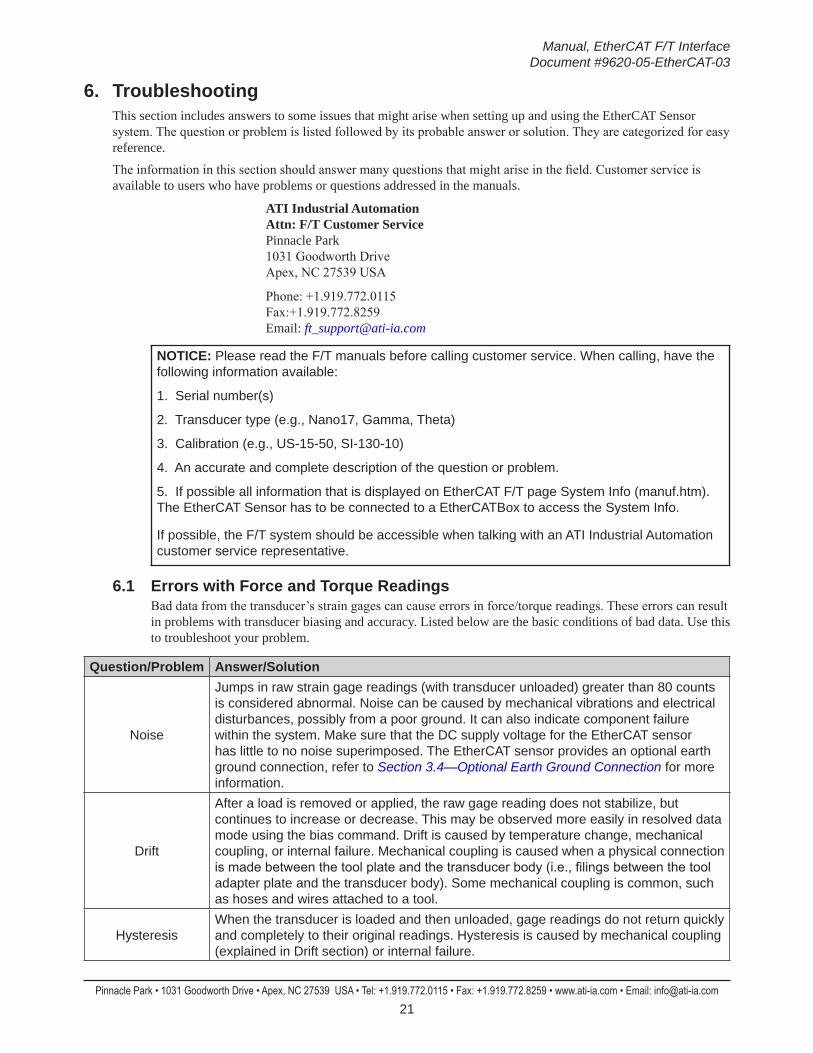
6. TroubleshootingThis section includes answers to some issues that might arise when setting up and using the EtherCAT Sensor system. The question or problem is listed followed by its probable answer or solution. They are categorized for easy reference.
The information in this section should answer many questions that might arise in the field. Customer service is available to users who have problems or questions addressed in the manuals.
ATI Industrial Automation Attn: F/T Customer Service Pinnacle Park 1031 Goodworth Drive Apex, NC 27539 USA
Phone: +1.919.772.0115 Fax:+1.919.772.8259 Email: [email protected]
NOTICE: Please read the F/T manuals before calling customer service. When calling, have the following information available:
1. Serial number(s)
2. Transducer type (e.g., Nano17, Gamma, Theta)
3. Calibration (e.g., US-15-50, SI-130-10)
4. An accurate and complete description of the question or problem.
5. If possible all information that is displayed on EtherCAT F/T page System Info (manuf.htm). The EtherCAT Sensor has to be connected to a EtherCATBox to access the System Info.
If possible, the F/T system should be accessible when talking with an ATI Industrial Automation customer service representative.
6.1 Errors with Force and Torque ReadingsBad data from the transducer’s strain gages can cause errors in force/torque readings. These errors can result in problems with transducer biasing and accuracy. Listed below are the basic conditions of bad data. Use this to troubleshoot your problem.
Question/Problem Answer/Solution
Noise
Jumps in raw strain gage readings (with transducer unloaded) greater than 80 counts is considered abnormal. Noise can be caused by mechanical vibrations and electrical disturbances, possibly from a poor ground. It can also indicate component failure within the system. Make sure that the DC supply voltage for the EtherCAT sensor has little to no noise superimposed. The EtherCAT sensor provides an optional earth ground connection, refer to Section 3.4—Optional Earth Ground Connection for more information.
Drift
After a load is removed or applied, the raw gage reading does not stabilize, but continues to increase or decrease. This may be observed more easily in resolved data mode using the bias command. Drift is caused by temperature change, mechanical coupling, or internal failure. Mechanical coupling is caused when a physical connection is made between the tool plate and the transducer body (i.e., filings between the tool adapter plate and the transducer body). Some mechanical coupling is common, such as hoses and wires attached to a tool.
HysteresisWhen the transducer is loaded and then unloaded, gage readings do not return quickly and completely to their original readings. Hysteresis is caused by mechanical coupling (explained in Drift section) or internal failure.
Manual, EtherCAT F/T Interface Document #9620-05-EtherCAT-03
Pinnacle Park • 1031 Goodworth Drive • Apex, NC 27539 USA • Tel: +1.919.772.0115 • Fax: +1.919.772.8259 • www.ati-ia.com • Email: [email protected] 22
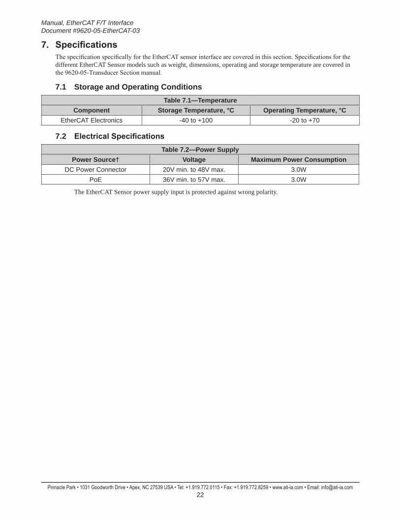
7. SpecificationsThe specification specifically for the EtherCAT sensor interface are covered in this section. Specifications for the different EtherCAT Sensor models such as weight, dimensions, operating and storage temperature are covered in the 9620-05-Transducer Section manual.
7.1 Storage and Operating ConditionsTable 7.1—Temperature
Component Storage Temperature, °C Operating Temperature, °CEtherCAT Electronics -40 to +100 -20 to +70
7.2 ElectricalSpecificationsTable 7.2—Power Supply
Power Source† Voltage Maximum Power Consumption DC Power Connector 20V min. to 48V max. 3.0W
PoE 36V min. to 57V max. 3.0W
The EtherCAT Sensor power supply input is protected against wrong polarity.

Manual, EtherCAT F/T Interface Document #9620-05-EtherCAT-03
Pinnacle Park • 1031 Goodworth Drive • Apex, NC 27539 USA • Tel: +1.919.772.0115 • Fax: +1.919.772.8259 • www.ati-ia.com • Email: [email protected] 23
8. Drawings
3rd
AN
GLE
PRO
JEC
TION
68.
5
4X T
ap M
6X1.
0 7
.6E
qual
ly S
pace
dC
usto
mer
Inte
rface
64.
678±
0.02
5 4
9.79
6±0.
025
27.
280±
0.02
5
2X
6 S
lip F
it 6
.35
Cus
tom
er In
terfa
ce
2X
6 S
lip F
it Th
ruC
usto
mer
Inte
rface
84.
2 4X
6
.8 T
hru
For M
6 S
HC
SE
qual
ly S
pace
dC
usto
mer
Inte
rface
Opt
iona
l Mou
ntin
gS
ide
Pat
tern
B.C
. 11
5
84.
290±
0.02
5
47.
250±
0.02
5
15.
750±
0.02
5
28.
750±
0.02
5
B.C
.63
45°
D
C P
ower
-X
+X
+Y-Y
Eth
erC
AT
(Opt
iona
l PoE
)
6.7
44.
5
52.
2
Tool
Ada
pter
Pla
te
Mou
ntin
g A
dapt
erP
late
Sen
sing
Ref
eren
ceFr
ame
Orig
in
Eth
erC
AT
LED
Indi
cato
rs
-Z+Z
Rin
g Te
rmin
al(F
or O
ptio
nal
Ear
th G
roun
d C
onne
ctio
n)
B.C
.50
6
Slip
Fit
6.3
5C
usto
mer
Inte
rface
25±
0.02
5
10
3.6
12
6
16 H
7 6.
3C
ham
fer 1
x 4
5C
usto
mer
Inte
rface
4X T
ap M
6X1.
0 8
.5E
qual
ly S
pace
dC
usto
mer
Inte
rface 4
5° M
embr
ane
Ven
t
Sen
sing
Ref
eren
ceFr
ame
Orig
in
+Y-Y
+X -X
Not
es:
Mat
eria
l: S
tain
less
Ste
el a
nd A
lum
inum
1.S
ensi
ng R
efer
ence
Fra
me
Orig
in a
t Sur
face
Cen
ter o
f Too
l Ada
pter
.2.
Do
not d
isas
sem
ble
trans
duce
r. D
oing
so
coul
d da
mag
e tra
nsdu
cer a
nd w
ill v
oid
war
rant
y.3.
For b
est a
ccur
acy,
tran
sduc
er m
ust b
e m
ount
ed to
a s
urfa
ce ri
gid
enou
gh to
sup
port
load
s 4.
with
out d
efle
ctio
n.C
able
s m
ust b
e co
nnec
ted
to tr
ansd
ucer
to m
aint
ain
prop
er s
eal.
5.
MO
UN
TIN
G S
IDE
SID
E V
IEW
TOO
L S
IDE
Rev.
Des
crip
tion
Initi
ator
Dat
e
01In
itial
Dra
win
gLC
S4/
16/2
015
B4:
51
2RE
VISI
ON
NO
TES:
UN
LESS
OTH
ERW
ISE
SPEC
IFIE
D.
DO
NO
T SC
ALE
DRA
WIN
G.
ALL
DIM
ENSI
ON
S A
RE IN
M
ILLIM
ETER
S.
DRA
WN
BY:
CHE
CKE
D B
Y:
L. S
trahl
er 4
/16/
15
P. F
usco
4/1
7/15
TITLE SC
ALE
SIZE
DRA
WIN
G N
UMBE
R
PRO
JEC
T #
SHEE
T
O
F 92
30-0
5-14
6914
0328
-501
PRO
PERT
Y O
F A
TI IN
DUS
TRIA
L A
UTO
MA
TION
, IN
C. N
OT
TO B
E RE
PRO
DUC
ED IN
AN
Y M
AN
NER
EXC
EPT
ON
ORD
ER O
R W
ITH P
RIO
R W
RITT
EN A
UTHO
RIZA
TION
OF
ATI.
1031
Goo
dwor
th Dr
ive, A
pex,
NC 27
539,
USA
Tel: +
1.919
.772.0
115
Em
ail: in
fo@ati
-ia.co
mFa
x: +1
.919.7
72.82
59
www
.ati-ia
.com
ISO
9001
Reg
ister
ed C
ompa
ny
A. S
trotz
er 4
/21/
15
9105
-EC
AT-D
elta
-IP65
Cus
tom
er D
raw
ing

Manual, EtherCAT F/T Interface Document #9620-05-EtherCAT-03
Pinnacle Park • 1031 Goodworth Drive • Apex, NC 27539 USA • Tel: +1.919.772.0115 • Fax: +1.919.772.8259 • www.ati-ia.com • Email: [email protected] 24
3rd
AN
GLE
PRO
JEC
TION
DC
Pow
er C
onne
ctor
3-P
in M
ale
M8
D-C
oded
ISO
ME
TRIC
VIE
W
Eth
erC
AT
Con
nect
or4-
Pin
Fem
ale
M12
D-C
oded
Pin
No.
Sig
nal
1V
+3
GN
D4
N/C
Pin
No.
Sig
nal
1TX
+2
RX
+3
TX-
4R
X-
She
llC
onne
ctor
Blo
ck H
ousi
ng
B4:
52
2RE
VISI
ON
NO
TES:
UN
LESS
OTH
ERW
ISE
SPEC
IFIE
D.
DO
NO
T SC
ALE
DRA
WIN
G.
ALL
DIM
ENSI
ON
S A
RE IN
M
ILLIM
ETER
S.
DRA
WN
BY:
CHE
CKE
D B
Y:
L. S
trahl
er 4
/16/
15
P. F
usco
4/1
7/15
TITLE SC
ALE
SIZE
DRA
WIN
G N
UMBE
R
PRO
JEC
T #
SHEE
T
O
F 92
30-0
5-14
6914
0328
-501
PRO
PERT
Y O
F A
TI IN
DUS
TRIA
L A
UTO
MA
TION
, IN
C. N
OT
TO B
E RE
PRO
DUC
ED IN
AN
Y M
AN
NER
EXC
EPT
ON
ORD
ER O
R W
ITH P
RIO
R W
RITT
EN A
UTHO
RIZA
TION
OF
ATI.
1031
Goo
dwor
th Dr
ive, A
pex,
NC 27
539,
USA
Tel: +
1.919
.772.0
115
Em
ail: in
fo@ati
-ia.co
mFa
x: +1
.919.7
72.82
59
www
.ati-ia
.com
ISO
9001
Reg
ister
ed C
ompa
ny
A. S
trotz
er 4
/21/
15
9105
-EC
AT-D
elta
-IP65
Cus
tom
er D
raw
ing

Manual, EtherCAT F/T Interface Document #9620-05-EtherCAT-03
Pinnacle Park • 1031 Goodworth Drive • Apex, NC 27539 USA • Tel: +1.919.772.0115 • Fax: +1.919.772.8259 • www.ati-ia.com • Email: [email protected] 25
9. Terms and Conditions of SaleThe following Terms and Conditions are a supplement to and include a portion of ATI’s Standard Terms and Conditions, which are on file at ATI and available upon request.
ATI warrants to Purchaser that force torque sensor products purchased hereunder will be free from defects in material and workmanship under normal use for a period of one year from the date of shipment. This warranty does not cover components subject to wear and tear under normal usage or those requiring periodic replacement. ATI will have no liability under this warranty unless: (a) ATI is given written notice of the claimed defect and a description thereof with thirty (30) days after Purchaser discovers the defect and in any event, not later than the last day of the warranty period and (b) the defective item is received by ATI not later than (10) days after the last day of the warranty period. ATI’s entire liability and Purchaser’s sole remedy under this warranty is limited to repair or replacement, at ATI’s election, of the defective part or item or, at ATI’s election, refund of the price paid for the item. The foregoing warranty does not apply to any defect or failure resulting from improper installation, operation, maintenance, or repair by anyone other than ATI.
ATI will in no event be liable for incidental, consequential, or special damages of any kind, even if TI has been advised of the possibility of such damages. ATI’s aggregate liability will in no event exceed the amount paid by the purchaser for the item which is the subject of claim or dispute. ATI will have no liability of any kind for failure of any equipment or other items not supplied by ATI.
No action against ATI, regardless of form, arising out of or in any way connected with products or services supplied hereunder, may be brought more than one year after the cause of action accrued.
No representation or agreement varying or extending the warranty and limitation of remedy provisions contained herein is authorized by ATI, and may not be relied upon as having been authorized by ATI, unless in writing and signed by an executive officer of ATI.
Unless otherwise agreed in writing by ATI, all designs, drawings, data, inventions, software, and other technology made or developed by ATI in the course of providing products and services hereunder, and all rights therein under any patent, copyright, or other law protecting intellectual property, shall be and remain ATI’s property. The sale of products or services hereunder does not convey any expressed or implied license under any patent, copyright, or other intellectual property right owned or controlled by ATI, whether relating to the products sold or any other matter, except for the license expressly granted below.
In the course of supplying products and services hereunder, ATI may provide or disclose to Purchaser confidential and proprietary information of ATI relating to the design, operation, or other aspects of ATI’s products. As between ATI and Purchaser, ownership of such information, including without limitation any computer software provided to Purchaser by ATI, shall remain in ATI and such information is licensed to Purchaser only for Purchaser’s use in operating the products supplied by ATI hereunder in Purchaser’s internal business operations.
Without ATI’s prior written permission, Purchaser will not use such information for any other purpose of provide or otherwise make such information available to any third party. Purchaser agrees to take all reasonable precautions to prevent any unauthorized use or disclosure of such information.
Purchaser will not be liable hereunder with respect to disclosure or use of information which: (a) is in the public domain when received from ATI, (b) is thereafter published or otherwise enters the public domain through no fault of Purchaser, (c) is in Purchaser’s possession prior to receipt from ATI, (d) is lawfully obtained by Purchaser from a third party entitled to disclose it, or (f) is required to be disclosed by judicial order or other governmental authority, provided that, with respect to such to maintain the confidentiality of such information.