Embed Size (px)
Citation preview

The purpose of this guide is to assist new helicopter pilots to setup their radio. Many basics will be covered, as well as explanations of certain choices and how one aspect affects another. Experienced pilots may want to skim through this guide. It first covers the preliminary transmitter programming steps, then swash plate, tail rotor, and throttle / pitch / revolutionmixing curves. Finally, it briefly covers the available compensation mixers, and optional use of the 7th and 8th channels. (Not applicable to RD6000 owners.)
While some helicopter setup theory is covered, the instructions from the manufacturer of your particular helicopter override any suggestions offered here. In the case of doubt, please contact your helicopter manufacturer or Airtronics customer service.
If you are setting up an electric helicopter, ensure that your motor is disconnected from the speed control while making any adjustments. Do not have your engine running while making adjustments if you have a glow or gasoline model.
Preliminary Transmitter Setup
Power on your transmitter. It will not operate however, until it is placed into the Normal (“N”) flight mode, with the throttle stick at the lowest position. If those conditions are not met, you will see an IDUP! or THHi! warning message and hear beeping. The two switches at the far upper left and right sides of your transmitter control the flight modes. Both must be positioned toward you to enter the Normal flight mode.
Select a model memory to use for your helicopter. Navigate to ETC > MSL, then press the Inc+/Yes button to enter that menu. Now use the Inc+/Yes or Dec-/No buttons to scroll through your model memories. After selecting the desired model memory, press the End key to confirm.
Ensure that your model memory is set to “heli” mode. The upper left corner of your screen will say either “heli” or “aero.” If it lists “aero”, switch to helicopter mode by navigating to ETC > TYP, press the right arrow key, then the Inc+/Yes key to confirm the change. Finally press the End key to return to the previous menu.

Name your model memory. Navigate to ETC > NAM, then press the right-arrow button to enter that menu. Use the four arrow keys to change the current letter or scroll to other letters. Press the End key when finished.
Due to the involved nature of helicopter programming options, you will need to disable the Basic menu structure to access the complete list of features. Navigate to ETC > BASIC, then use the Inc+/Yes key to toggle that option to OFF.
The transmitter has flight mode switches installed in the traditional locations for airplane use. For helicopter's, you may want to swap the locations. This can be done by carefully removing the back housing, then removing the switches and swapping their positions. You can also send the radio to the service department for that modification.
Tip: If you use a flight simulator, it would be advisable to make sure the flight mode switches on your flight sim controller and on your Airtronics transmitter operate identically. This will ensure that any “muscle memory” you develop with the flight simulator will be correct when you fly the real thing.
The direction of your switches can be reversed electronically by navigating to ETC > SWR and use the Inc+/Yes key to toggle the option between NOR and REV.
Swash Plate Settings
A helicopter imparts control inputs to the main rotor head through the swash plate. There are two different methods used to give inputs to the swash plate: CCPM mixing, and mechanical mixing. With a CCPM setup, you have three servos working in unison to tilt, raise or lower the swash plate. Mechanical mixing uses three servos that work independently: one for left/right cyclic, one for fore/aft cyclic, and one for collective pitch.
Select the appropriate swash plate type. Navigate to ETC > SWH, and use the Inc+/Yes or Dec-/No keys to scroll through the available swash plate types. The diagram below indicates the correct CCPM mode to choose if you have a CCPM helicopter.
There is one exception for the swash plate type that we are aware of. The Thunder Tiger Mini Titan helicopter has a unique system that results in negative collective pitch being applied when the swash plate is raised. For that reason, if you have the Mini Titan you will need to use the CP3F option, and attach your front servo to the Ch1 “Elevator” slot, your rearleft servo to the Ch2 “Aileron” slot, and your rearright servo to the Ch6 “Pitch” slot.
While the diagram above lists the CCPM servos as “elevator” “aileron” and “pitch” they do not actually perform those functions because they work in unison. Regardless, when programming servospecific options in your radio, the servos will be identified that way.
If you have not already done so, make sure your rotor head linkages are setup correctly. Consult your helicopter's manual for details. For your convenience, a brief summary of typical rotorhead setup is listed below.
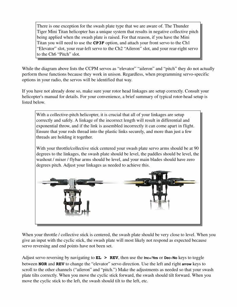
With a collectivepitch helicopter, it is crucial that all of your linkages are setup correctly and safely. A linkage of the incorrect length will result in differential and exponential throw, and if the link is assembled incorrectly it can come apart in flight. Ensure that your rods thread into the plastic links securely, and more than just a few threads are holding it together.
With your throttle/collective stick centered your swash plate servo arms should be at 90 degrees to the linkages, the swash plate should be level, the paddles should be level, the washout / mixer / flybar arms should be level, and your main blades should have zero degrees pitch. Adjust your linkages as needed to achieve this.
When your throttle / collective stick is centered, the swash plate should be very close to level. When you give an input with the cyclic stick, the swash plate will most likely not respond as expected because servo reversing and end points have not been set.
Adjust servo reversing by navigating to EL > REV, then use the Inc+/Yes or Dec-/No keys to toggle between NOR and REV to change the “elevator” servo direction. Use the left and right arrow keys to scroll to the other channels (“aileron” and “pitch.”) Make the adjustments as needed so that your swash plate tilts correctly. When you move the cyclic stick forward, the swash should tilt forward. When you move the cyclic stick to the left, the swash should tilt to the left, etc.

Adjust endpoints so that the swash plate is not overcontrolled or “binds.” Navigate to EL > EPA and make adjustments as needed. Move the cyclic stick forward or backward to adjust the forward or backward “elevator” endpoint. Use the right-arrow key to scroll to the “aileron” and “pitch” channels and repeat the process.
Note: When using CCPM, endpoint adjustments effect the function, not one particular servo.
Throttle and Pitch Curves
The throttle / collective stick on your transmitter controls two functions at the same time. As the name implies, it controls the amount of throttle applied, as well as the pitch of your main rotor blades. Fivepoint curves are available and allow you to custom tailor how your helicopter performs in each of the four flight modes. (N, 1, 2 and 3.)
Traditionally, the Normal “N” flight mode is set up to perform somewhat like a fixedpitch helicopter, with a low stick position you have zero throttle and zero degrees pitch, and with a high stick position you have full throttle, and 912 degrees of pitch. Flight modes 1 and 2 are traditionally setup for aerobatic flight, with varying amounts of throttle being applied at all positions, and your pitch varying from negative to positive. Flight mode 3 is generally used for practicing auto rotations or to cut throttle if you anticipate an imminent crash. Throttle is set to zero or idle for all stick positions, and pitch varies from negative to positive.
Consult your helicopter manual regarding suggested starting values for throttle and pitch curves. If no suggestions are listed, you can start with some basic throttle and pitch curves. See the diagram below.
Set the throttle curve for each of your four flight modes. Navigate to TH > CVPH, then P3, P2, P1, PL. The lowest point is PL, and the highest point in PH. The flight mode you are modifying is listed in the lowerleft section of your screen, under “FMode.” Use the F-Mode button to scroll through your four flight modes and set your various curves.
Repeat the same procedure for your pitch curves. Navigate to PF > CVPH, then P3, P2, P1, PL. The lowest point is PL, and the highest point in PH.

Revolution Mixing
Revolution mixing applies rudder input based upon your throttle / collective stick position. This helps to compensate for changes in torque being applied to the main rotor, which will make the helicopter spin. Today's gyros do a very good job of keeping the tail steady, so there is rarely a need to use this feature. If you have a headinghold gyro, revolution mixing must be disabled for it to function properly. Even if you plan to use revolution mixing, it is best to disable it during the initial setup of your model. Navigate to RU > RV.H, then RV.M, and RV.L. The lowest point is RV.L, and the highest point in RV.H. The flight mode you are modifying is listed in the lowerleft section of your screen, under “FMode.” Use the F-Mode button and up / down arrow keys to scroll through your four flight modes and zero all values for each flight mode and all three points.
Tail and Remote Gain Settings
Proper setup of your rudder linkage is essential for proper control and to ensure your gyro is able to perform to the best of abilities. With your rudder stick centered, the rudder servo arm should be at 90 degrees to the linkage, and the pitch lever that the linkage connects to should be at 90 degrees for most helicopters. Consult your helicopter's manual to verify this.
Many gyros have an additional servo lead that plugs into the 5th channel to control the gain and headinghold/rate modes of the gyro with your transmitter. Each flight mode has two settings, controlled by the twoposition “Gyro” switch. If your gyro has the remote gain feature, navigate to G > GYR. The flight mode you are modifying is listed in the lowerleft section of your screen, under “FMode.” Use the F-Mode button to scroll through your four flight modes and set your various gain settings. Now toggle your “Gyro” switch to the other position and repeat the process.
Rate vs. HeadingHold Gyros
A “rate” gyro is a simple and lowcost gyro that senses the approximate amount that your tail drifts, and responds with an estimated control input to counteract the drift. It does not lock the position of your tail, and will allow it to weather vane.
A “headinghold” gyro is more advanced and does a much better job of keeping the tail steady. A simple way to think of how it works is to imagine that it notices a drift, calculates how much it drifted, then applies enough control input (if possible) to return the tail to the commanded heading. Your tail will not weather vane, so you must coordinate your turns with both cyclic and rudder inputs.

Gain Values
Regardless of your gyro type, you must set an appropriate gain value. The gain value tells the gyro how much it needs to amplify the compensation commands. Too low of a gain value will let the tail drift easily, and too high of a gain valve will make the gyro overcompensate which results in a tail that “wags.” A good starting point is 50%, then adjust it as necessary after your test flights.
Any change that effects the speed or efficiency of the main or tail rotors can result in a need to change the gain value. Some of the factors include:
● Changes to your throttle or pitch curves● Changing the length or type of main or tail rotor blades● Forward flight, backward flight, or flight in a steady breeze (increases
efficiency because it brings lessturbulent air to the rotors.)● Pinion gear, main gear and motor● Tail drive gears / pulleys
Compensation Mixers, and Channels 7 / 8
Your remote control helicopter's setup is now complete. This section covers optional use of the two available compensation mixers. A CMix will mix one channel with another, allowing you to link them. Some of the reasons for the using the CMix include:
Reduce CCPM InteractionsCCPM interactions occur when an unintended swash plate movement results from a control input. For example, when applying a full collectivepitch command, your swash plate may also tilt forward slightly which would add an unintended forward cyclic effect. This is the result of imperfect linkage geometry, and the fact that no two servos are completely alike.You can mix Pitch to Aileron and/or Pitch to Elevator to counteract this effect.
Help Maintain a Constant HeadSpeed Without Using a GovernorAny cyclic control input will place a higher load to your main rotor. This increased load will reduce the head speed, and in more demanding maneuvers this change can be significant. By mixing Aileron to Throttle and Elevator to Throttle, you can help compensate the increased load. This should only be done after properly adjusting your throttle and pitch curves to achieve a nearly constant head speed throughout your pitch range.The RaptorTechnique* website has a great tutorial on how to set this up:http://www.raptortechnique.com/throttlemix.htm
Link a Channel to Your 7th or 8th Channel.This just links one channel to another. You choose a upper and lower percentage, and that will effect how much the two channels correlate. This will give you indirect proportional control over your 7th and 8th channels if so desired.
*RaptorTechnique.com is not affiliated with Airtronics or Global Hobby Distributors.

For more information on how to use the compensation mixers, consult your Airtronics manual.
The 7th and 8th channels can also be directly controlled by using the AUX1 and AUX2 twoposition switches on the front of the transmitter. Some common uses include controlling a governor, onboard glow heater, lights, or retracts.
For more information on this and other Airtronics products,please visit our web site at http://www.airtronics.net
For Airtronics support in the USA and North America,please visit our web forum at http://globalservices.globalhobby.com
or send an email to [email protected]
For Airtronics support via mail, phone or fax, please use the following:
Global Services18480 Bandilier Circle
Fountain Valley, CA 92708Phone: (714) 9630329 / Fax: (714) 9646236
All Contents Copyright © 2008, Global Hobby DistributorsVersion 1, October 2008 – All Rights Reserved
Contents courtesy of Farrell Farahbod – Airtronics Technical Support