Embed Size (px)
Citation preview

Enterprise Tablet
Integrator Guide
ET5X
MN-002776-01


ET5XINTEGRATOR GUIDE
MN-002776-01Rev. A
May 2016

ii ET5X Integrator Guide
© 2016 Symbol Technologies LLC, a subsidiary of Zebra Technologies Corporation. All rights reserved.
Zebra and the stylized Zebra head are trademarks of ZIH Corp., registered in many jurisdictions worldwide. All other trademarks are the property of their respective owners.

iii
Revision HistoryChanges to the original guide are listed below:
Change Date Description
Rev A 5/2016 Initial release.

iv ET5X Integrator Guide

TABLE OF CONTENTS
Revision History.................................................................................................................................... iii
About This GuideIntroduction ........................................................................................................................................... ix
Documentation Set ......................................................................................................................... ixConfigurations....................................................................................................................................... ixChapter Descriptions ............................................................................................................................ xNotational Conventions......................................................................................................................... xRelated Documents and Software ........................................................................................................ xiService Information............................................................................................................................... xi
Chapter 1: Getting StartedIntroduction .......................................................................................................................................... 1-1Unpacking ............................................................................................................................................ 1-1Getting Started ..................................................................................................................................... 1-1
Installing a micro SIM Card (ET55 Only) ....................................................................................... 1-1Resetting the ET5X .............................................................................................................................. 1-9
Chapter 2: AccessoriesIntroduction .......................................................................................................................................... 2-1Charge Only Cradle ............................................................................................................................. 2-4
Installing the Insert ......................................................................................................................... 2-5Communication and Charging Cradle .................................................................................................. 2-6
Installing the Insert ......................................................................................................................... 2-7Rugged Communication and Charging Cradle .................................................................................... 2-8Rugged Frame ..................................................................................................................................... 2-10Expansion Back ................................................................................................................................... 2-13
Installation ...................................................................................................................................... 2-13Programming the SE4710/SE4750 Expansion Backs ................................................................... 2-15HID Keyboard Emulation Bar Code ............................................................................................... 2-15Replacement Hand Strap ............................................................................................................... 2-15

vi ET5X Integrator Guide
Chapter 3: SoftwareIntroduction .......................................................................................................................................... 3-1Factory Reset ...................................................................................................................................... 3-1System Updates .................................................................................................................................. 3-1
Creating Installation USB Thumb Drive ......................................................................................... 3-2Setup Using Communication Dock ................................................................................................ 3-3Setup Using a USB Hub ................................................................................................................ 3-4Updating the Operating System ..................................................................................................... 3-4
Checking Versions ............................................................................................................................... 3-5Check ULPMC Version .................................................................................................................. 3-5Check BIOS Version ...................................................................................................................... 3-6Check Operating System Version .................................................................................................. 3-7
Downgrade to Previous Operating System Version ............................................................................ 3-7Downgrading ULPMC via EFI Shell ............................................................................................... 3-7Downgrade Operating System ....................................................................................................... 3-8Determining Modem Type .............................................................................................................. 3-9
Data Capture Application Development ............................................................................................... 3-9Application Installation ......................................................................................................................... 3-9
Install from the Internet .................................................................................................................. 3-9Install from a network ..................................................................................................................... 3-9
Chapter 4: Maintenance and TroubleshootingIntroduction .......................................................................................................................................... 4-1Maintaining the ET5X .......................................................................................................................... 4-1Battery Safety Guidelines .................................................................................................................... 4-1Cleaning ............................................................................................................................................... 4-2
Materials Required ......................................................................................................................... 4-2Cleaning the ET5X ......................................................................................................................... 4-2
Housing .................................................................................................................................... 4-2Display ..................................................................................................................................... 4-3Power Connector ..................................................................................................................... 4-3
Cleaning Cradle Connectors .......................................................................................................... 4-3Cleaning Expansion Back Connectors ........................................................................................... 4-3Cleaning Frequency ....................................................................................................................... 4-4
Troubleshooting ................................................................................................................................... 4-5ET5X .............................................................................................................................................. 4-5Charge Only Cradle ....................................................................................................................... 4-6Communication and Charging Cradles .......................................................................................... 4-6Expansion Backs ........................................................................................................................... 4-7
Appendix A: SpecificationsTechnical Specifications ...................................................................................................................... A-1
ET5X .............................................................................................................................................. A-1SE4710 Expansion Back Decode Range ............................................................................................ A-4SE4750 Expansion Back Decode Range ............................................................................................ A-5
SE4750 SR Decode Ranges ......................................................................................................... A-5SE4750 MR Decode Ranges ......................................................................................................... A-6
Accessory Specifications ..................................................................................................................... A-7

Table of Contents vii
Charge Only Cradle ....................................................................................................................... A-7Communication and Charging Cradle ............................................................................................ A-7Rugged Communication and Charging Cradle .............................................................................. A-8Expansion Backs ........................................................................................................................... A-8

viii ET5X Integrator Guide
ABOUT THIS GUIDE
IntroductionThis guide provides information about configuring and setting up the ET5X and accessories.
Documentation SetThe documentation set for the ET5X is divided into guides that provide information for specific user needs.
• ET5X Quick Reference Guide - describes how to get the ET5X tablet up and running.
• ET5X User Guide - describes how to use the ET5X tablet.
• ET5X Integrator Guide - describes how to setup, the ET5X and accessories.
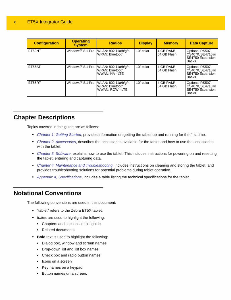
ConfigurationsThis guide covers the following configurations:
NOTE Screens and windows pictured in this guide are samples and can differ from actual screens.
Configuration OperatingSystem Radios Display Memory Data Capture
ET50NE Windows® 8.1 Pro WLAN: 802.11a/b/g/nWPAN: Bluetooth
8” color 4 GB RAM/64 GB Flash
Optional RS507, CS4070, SE4710 or SE4750 Expansion Backs
ET55AE Windows® 8.1 Pro WLAN: 802.11a/b/g/nWPAN: BluetoothWWAN: NA - LTE
8” color 4 GB RAM/64 GB Flash
Optional RS507, CS4070, SE4710 or SE4750 Expansion Backs
ET55RE Windows® 8.1 Pro WLAN: 802.11a/b/g/nWPAN: BluetoothWWAN: ROW - LTE
8” color 4 GB RAM/64 GB Flash
Optional RS507, CS4070, SE4710 or SE4750 Expansion Backs
x ET5X Integrator Guide
Chapter DescriptionsTopics covered in this guide are as follows:
• Chapter 1, Getting Started, provides information on getting the tablet up and running for the first time.
• Chapter 2, Accessories, describes the accessories available for the tablet and how to use the accessories with the tablet.
• Chapter 3, Software, explains how to use the tablet. This includes instructions for powering on and resetting the tablet, entering and capturing data.
• Chapter 4, Maintenance and Troubleshooting, includes instructions on cleaning and storing the tablet, and provides troubleshooting solutions for potential problems during tablet operation.
• Appendix A, Specifications, includes a table listing the technical specifications for the tablet.
Notational ConventionsThe following conventions are used in this document:
• “tablet” refers to the Zebra ET5X tablet.
• Italics are used to highlight the following:• Chapters and sections in this guide• Related documents
• Bold text is used to highlight the following:• Dialog box, window and screen names• Drop-down list and list box names• Check box and radio button names• Icons on a screen• Key names on a keypad• Button names on a screen.
ET50NT Windows® 8.1 Pro WLAN: 802.11a/b/g/nWPAN: Bluetooth
10” color 4 GB RAM/64 GB Flash
Optional RS507, CS4070, SE4710 or SE4750 Expansion Backs
ET55AT Windows® 8.1 Pro WLAN: 802.11a/b/g/nWPAN: BluetoothWWAN: NA - LTE
10” color 4 GB RAM/64 GB Flash
Optional RS507, CS4070, SE4710 or SE4750 Expansion Backs
ET55RT Windows® 8.1 Pro WLAN: 802.11a/b/g/nWPAN: BluetoothWWAN: ROW - LTE
10” color 4 GB RAM/64 GB Flash
Optional RS507, CS4070, SE4710 or SE4750 Expansion Backs
Configuration OperatingSystem Radios Display Memory Data Capture

About This Guide xi
• Bullets (•) indicate:• Action items• Lists of alternatives• Lists of required steps that are not necessarily sequential.
• Sequential lists (e.g., those that describe step-by-step procedures) appear as numbered lists.
Related Documents and SoftwareThe following documents provide more information about the ET5X tablets.
• ET5X Quick Reference Guide, p/n MN001844Axx
• ET5X User Guide, p/n MN001843Axx
For the latest version of this guide and all guides, go to: http://www.zebra.com/support.
Service InformationIf you have a problem with your equipment, contact Zebra Global Customer Support for your region. Contact information is available at: http://www.zebra.com/support.
When contacting support, please have the following information available:
• Serial number of the unit
• Model number or product name
• Software type and version number.
Zebra responds to calls by email, telephone or fax within the time limits set forth in support agreements.
If your problem cannot be solved by Zebra Customer Support, you may need to return your equipment for servicing and will be given specific directions. Zebra is not responsible for any damages incurred during shipment if the approved shipping container is not used. Shipping the units improperly can possibly void the warranty.
If you purchased your Zebra business product from a Zebra business partner, contact that business partner for support.

xii ET5X Integrator Guide

CHAPTER 1 GETTING STARTED
IntroductionThis chapter explains how to set the device up for the first time.
UnpackingCarefully remove all protective material from around the ET5X and save the shipping container for later storage and shipping.
Verify that you received all equipment listed below:
• Table with lithium-ion battery
• Quick Reference Guide.
Inspect the equipment for damage. If you are missing any equipment or if you find any damaged equipment, contact the Zebra Support Center immediately. See page xi for contact information.
Getting StartedIn order to start using the ET5X for the first time:
• install the micro SIM Card (ET55 only)
• install microSD card (optional)
• start the ET5X
• configure the ET5X.
Installing a micro SIM Card (ET55 Only)
CAUTION Do not use nano to micro SIM card adapters.

1 - 2 ET5X Integrator Guide
To install a micro SIM card:
1. Press the Power button to turn off the ET55.
2. Lift the notched corner of the battery cover.
Figure 1-1 Removing the Battery Cover
3. Carefully lift the battery cover off the ET55.
4. On the 8” version, push the two locking tabs up, then pull up on the tab to remove battery.
On the 10” version, push the two locking tabs up (1), then, using index fingers, lift the battery up (2).
Figure 1-2 Removing the Battery - 8”
Pull Tab
8” Version
Locking Tabs

Getting Started 1 - 3
Figure 1-3 Removing the Battery - 10”
5. Insert the micro SIM card with contacts facing down.
Figure 1-4 Insert SIM Card
6. Push the SIM card in and ensure that it locks into place.
7. Replace the battery.
On the 10” version, ensure that the two battery latches engage.
2.LIFT UP
2.LIFT UP
1.RELEASE LOCKING
1.RELEASE LOCKING 10” Version
Locking Tabs
8” Version 10” Version
1 - 4 ET5X Integrator Guide
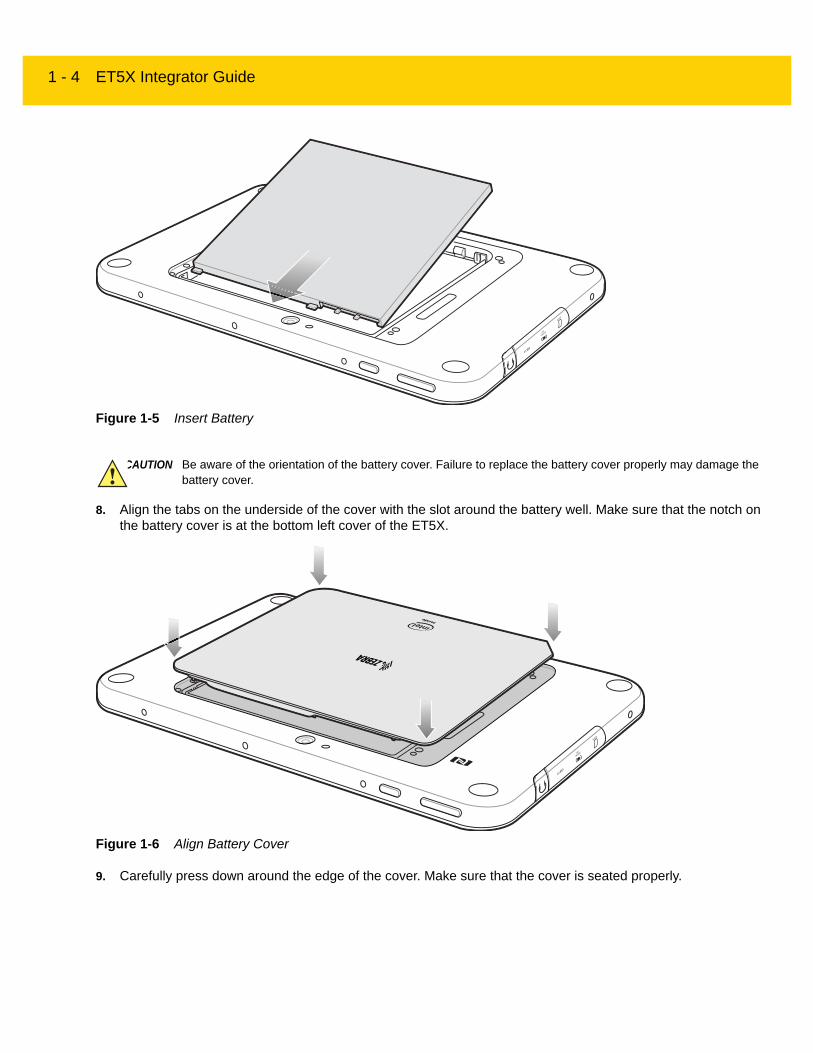
Figure 1-5 Insert Battery
8. Align the tabs on the underside of the cover with the slot around the battery well. Make sure that the notch on the battery cover is at the bottom left cover of the ET5X.
Figure 1-6 Align Battery Cover
9. Carefully press down around the edge of the cover. Make sure that the cover is seated properly.
CAUTION Be aware of the orientation of the battery cover. Failure to replace the battery cover properly may damage the battery cover.

Getting Started 1 - 5
Figure 1-7 Press Down on Battery Cover
10. Press Power button to turn on the ET55.
Use the Communication and Charging Cradle, Rugged Communication and Charging Cradle or Charge Only Cradle to charge the ET5X.
Figure 1-8 ET5X Cradles
1. If using the Communication and Charging Cradle, open the bottom access door and hold it to the back of the tablet.
2. Align the ET5X with the alignment pins on the cradle.
3. Insert the ET5X into the cradle. Note that the Communication and Charging Cradles contains a locking mechanism that locks the ET5X to the cradle.
NOTE The Charge Only Cradle (CRD-ET5X-1SCG1) and the Communication and Charge Cradle (CRD-ET5X-1SCOM1) come with two inserts; tall insert and short insert. Install the tall insert when using an ET5X without a Rugged Frame or Expansion Pack. Install the small insert when using an ET5X with an Expansion Pack and without a Rugged Frame. Do not install either insert when using the ET5X with the Rugged Frame.
The Rugged Communication and Charge Cradle (CRD-ET5X-1SCOM1R) does not come with inserts. Use with ET5X and Rugged Frame with IO Adapter.
Communication CradleCharge Only Cradle
Short Insert
Rugged Communication Cradle
Tall Insert

1 - 6 ET5X Integrator Guide
Figure 1-9 Insert ET5X into Charge Only Cradle
Figure 1-10 Insert ET5X with Rugged Frame into Communication and Charging Cradle

Getting Started 1 - 7
Figure 1-11 Insert ET5X with Rugged Frame and IO Adapter into Rugged Communication and Charging Cradle
4. The ET5X Charging LED indicates charging.
5. To remove the ET5X from the Charge Only Cradle, hold the cradle down with one hand and lift the ET5X.
1 - 8 ET5X Integrator Guide
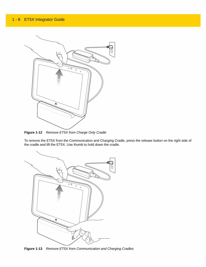
Figure 1-12 Remove ET5X from Charge Only Cradle
To remove the ET5X from the Communication and Charging Cradle, press the release button on the right side of the cradle and lift the ET5X. Use thumb to hold down the cradle.
Figure 1-13 Remove ET5X from Communication and Charging Cradles

Getting Started 1 - 9
The main battery usually fully charges in less than three hours. If an Expansion Back is attached, the main battery fully changes in less than 4.5 hours.
Resetting the ET5X
Resetting the ET5X returns Windows to original factory settings.
To reset the ET5X:
1. Swipe-in from the right edge of the display.
2. Touch Settings > Change PC settings > Update and recovery > Recovery.
3. Under Remove everything and reinstall Windows, touch Get started.
4. Read the warning and touch Next.
Table 1-1 Charging Indicator
LED Indication
Off ET5X is not in the cradle. ET5X is not seated properly. Cradle is not powered.
Orange ET5X is charging.
Green Charging complete.Note: When the battery is initially inserted in the ET5X, the amber LED flashes once if the battery power is low or the battery is not fully inserted.
Red Error in charging; check placement of the ET5X.
CAUTION Resetting the ET5X erases all data from the ET5X, including your account configuration, applications, music, pictures and files. Make sure that you back up all the required data before you proceed.

1 - 10 ET5X Integrator Guide

CHAPTER 2 ACCESSORIES
IntroductionThe ET5X accessories provide a variety of product support capabilities. Table 2-1 lists the accessories available.
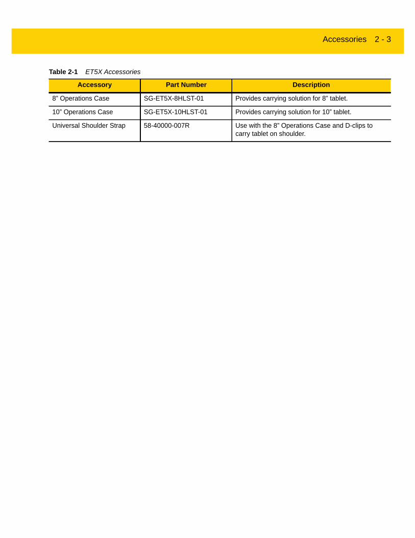
Table 2-1 ET5X Accessories
Accessory Part Number Description
Cradles
Charge Only Cradle CRD-ET5X-1SCG1 Charges the ET5X main battery. Requires power supply PWR-WGA12V60W-1WW.
Communication and Charging Cradle
CRD-ET5X-1SCOM1 Charges the ET5X main battery. Requires power supply PWR-WGA12V60W-1WW.
Rugged Communication and Charging Cradle
CRD-ET5X-1SCOM1R Charges the ET5X main battery. Supports ET5X with rugged frame and rugged IO Adapter. Requires power supply PWR-WGA12V60W-1WW.
Chargers
Power Supply PWR-WGA12V60W-1WW Provides power to the Charge Only Cradle and the Communication and Charging Cradles.
Miscellaneous
Replacement 8” Internal Battery
BTRY-ET5X-8IN1-01 Replacement battery for 8” tablet.
Replacement 10” Internal Battery
BTRY-ET5X-10IN1-01 Replacement battery for 10” tablet.
Replacement 8” Battery Cover
KT-ET5X-8BTDR1-01 Replacement battery cover for 8” tablet.
Replacement 10” Battery Cover
KT-ET5X-10BTDR1-01 Replacement battery cover for 10” tablet.

2 - 2 ET5X Integrator Guide
8” Rugged Frame with IO Adapter
SG-ET5X-8RCSE1-02 Add extra protection for the 8” tablet and IO Adapter for connection to the Rugged Communication and Charging Cradle.
10” Rugged Frame with IO Adapter
SG-ET5X-10RCSE1-01 Add extra protection for the 10” tablet and IO Adapter for connection to the Rugged Communication and Charging Cradle.
Replacement Rugged IO Connector
SG-ET5X-RGIO1-01 Replacement rugged IO connector for the Rugged Frames.
8” SE4750 Expansion Back ZBK-ET5X-8SCN5-01 Provides data capture using the SE4750 scan engine, rotating hand strap and slot for optional Power Pack.
8” SE4710 Expansion Back ZBK-ET5X-8SCN1-01 Provides data capture using the SE4710 scan engine, rotating hand strap and slot for optional Power Pack.
8” Expansion Back ZBK-ET5X-8RH1-01 Provides rotating hand strap and slot for optional Power Pack.
10” SE4750 Expansion Back ZBK-ET5X-10SCN5-01 Provides data capture using the SE4750 scan engine, rotating hand strap and slot for optional Power Pack.
10” SE4710 Expansion Back ZBK-ET5X-10SCN1-01 Provides data capture using the SE4710 scan engine, rotating hand strap and slot for optional Power Pack.
10” Expansion Back ZBK-ET5X-10RH1-01 Provides rotating hand strap and slot for optional Power Pack.
Power Pack BTRY-ET5X-PRPK1-01 Provides additional power for charging the ET5X battery using an Expansion Back.
Active Stylus KT-ET5X-ASTY1-01 Provides easy writing, drawing, and navigation and accuracy with the thin tip and hovering capabilities.
Replacement Expansion Back Hand Strap
SG-ET5X-RHTP1-01 Replacement hands strap for Expansion Backs.
Coiled Stylus Tether SG-ET5X-SLTETR-01 Secures a stylus to the hand strap on the Expansion Backs.
10” Screen Protector KT-ET5X-10SCRN1-01 Provides additional screen protection for 10” tablet (5-pack).
8” Screen Protector KT-ET5X-8SCRN1-01 Provides additional screen protection for 8” tablet (5-pack).
10” Screen Protector (Rugged Frame)
KT-ET5X-8SCRN1-01 Provides additional screen protection for 10” tablet with Rugged Frame (5-pack).
8” Screen Protector (Rugged Frame)
KT-ET5X-10SCRN1-02 Provides additional screen protection for 8” tablet with Rugged Frame (5-pack).
Table 2-1 ET5X Accessories
Accessory Part Number Description
Accessories 2 - 3
8” Operations Case SG-ET5X-8HLST-01 Provides carrying solution for 8” tablet.
10” Operations Case SG-ET5X-10HLST-01 Provides carrying solution for 10” tablet.
Universal Shoulder Strap 58-40000-007R Use with the 8” Operations Case and D-clips to carry tablet on shoulder.
Table 2-1 ET5X Accessories
Accessory Part Number Description

2 - 4 ET5X Integrator Guide
Charge Only Cradle
This section describes how to use a Charge Only Cradle with the ET5X. The Charge Only Cradle ships with an insert that must be installed when inserting an ET5X without the protective boot installed.
The Charge Only Cradle:
• Provides power for operating the ET5X.
• Charges the ET5X’s battery.
Figure 2-1 Charge Only Cradle - Front View
Figure 2-2 Charge Only Cradle - Rear View
The ET5X’s charge LED shows the status of the battery charging in the ET5X. See Table 1-1 on page 1-9 for charging status indications.
The battery charges in less than three hours. If an Expansion Back is attached with Power Pack, the main battery fully charges in less than 4.5 hours and the Power Pack charges in less than 3.5 hours.
CAUTION Ensure that you follow the guidelines for battery safety described in Battery Safety Guidelines on page 4-1.
Charging PinsGuide Pins Insert
Power Input
Accessories 2 - 5
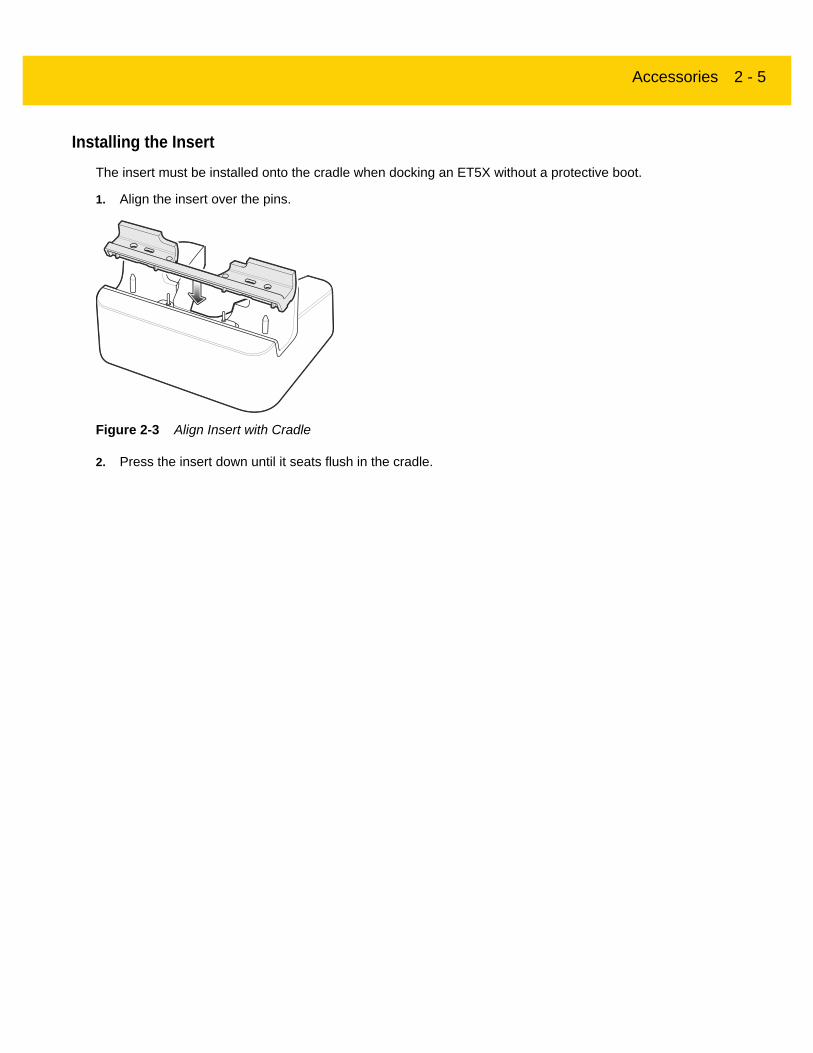
Installing the InsertThe insert must be installed onto the cradle when docking an ET5X without a protective boot.
1. Align the insert over the pins.
Figure 2-3 Align Insert with Cradle
2. Press the insert down until it seats flush in the cradle.

2 - 6 ET5X Integrator Guide
Communication and Charging Cradle
This section describes how to use a Communication and Charing Cradle with the ET5X.
The Communication and Charging cradle:
• Provides power for operating the ET5X.
• Provides ports for connecting USB devices to the tablet, video output and connection to a LAN.
Figure 2-4 Communication and Charging Cradle - Front View
Figure 2-5 Communication and Charging Cradle - Rear View
The ET5X’s amber charge LED shows the status of the battery charging in the ET5X. See Table 1-1 on page 1-9 for charging status indications.
CAUTION Ensure that you follow the guidelines for battery safety described in Battery Safety Guidelines on page 4-1.
Release Button
Locking Latches
Docking Connector
Charging Pins
Guide Pins Insert
USB 3.0 Ports LAN (RJ45) PortPower Input HDMI Port

Accessories 2 - 7
The battery charges in less than three hours. If an Expansion Back is attached with Power Pack, the main battery fully charges in less than 4.5 hours and the Power Pack charges in less than 3.5 hours.
Figure 2-6 Communication and Charging Cradle - Setup
Installing the InsertThe insert must be installed onto the cradle when docking an ET5X without a protective boot.
1. Align the insert over the pins.
Figure 2-7 Align Insert with Cradle
2. Press the insert down until it seats flush in the cradle.

2 - 8 ET5X Integrator Guide
Rugged Communication and Charging Cradle
This section describes how to use a Rugged Communication and Charing Cradle with the ET5X.
The Rugged Communication and Charging cradle:
• Provides power for operating the ET5X.
• Provides ports for connecting USB devices to the tablet, video output and connection to a LAN.
Figure 2-8 Rugged Communication and Charging Cradle - Front View
Figure 2-9 Rugged Communication and Charging Cradle - Rear View
The ET5X’s amber charge LED shows the status of the battery charging in the ET5X. See Table 1-1 on page 1-9 for charging status indications.
CAUTION Ensure that you follow the guidelines for battery safety described in Battery Safety Guidelines on page 4-1.
Release Button
Locking Latches
Rugged Docking Connector
Charging Pins
Guide Pins
USB 3.0 Ports LAN (RJ45) PortPower Input HDMI Port
Accessories 2 - 9
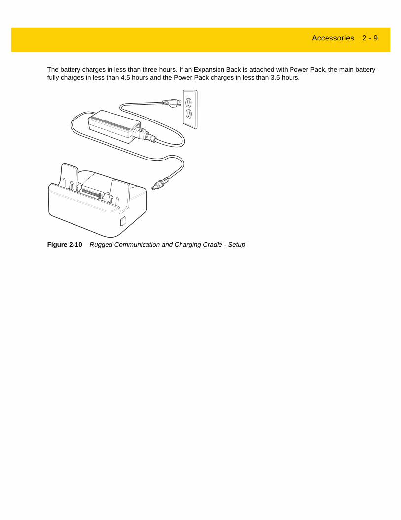
The battery charges in less than three hours. If an Expansion Back is attached with Power Pack, the main battery fully charges in less than 4.5 hours and the Power Pack charges in less than 3.5 hours.
Figure 2-10 Rugged Communication and Charging Cradle - Setup

2 - 10 ET5X Integrator Guide
Rugged FrameThe Rugged Frame (8 inch and 10 inch) adds additional protection to the ET5X. Use the Rugged I/O Adapter when docking the ET5X into the Rugged Communications and Charging Cradle.
1. Open the access cover.
Figure 2-11 Open Access Door
2. If installing the Rugged IO Adapter, pull the access cover away from the ET5X until it separates from the ET5X.
Figure 2-12 Remove Access Door
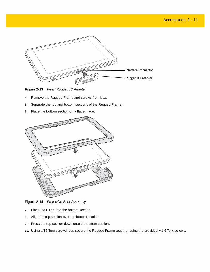
3. Insert the Rugged IO Adapter onto the tablet.
Accessories 2 - 11
Figure 2-13 Insert Rugged IO Adapter
4. Remove the Rugged Frame and screws from box.
5. Separate the top and bottom sections of the Rugged Frame.
6. Place the bottom section on a flat surface.
Figure 2-14 Protective Boot Assembly
7. Place the ET5X into the bottom section.
8. Align the top section over the bottom section.
9. Press the top section down onto the bottom section.
10. Using a T6 Torx screwdriver, secure the Rugged Frame together using the provided M1.6 Torx screws.
Rugged IO Adapter
Interface Connector

2 - 12 ET5X Integrator Guide
Figure 2-15 Secure 8” Rugged Frame
Figure 2-16 Secure 10” Rugged Frame
11. Torque the screws to 12 N-cm.

Accessories 2 - 13
Expansion BackThe Expansion Backs provide data capture and or Power Pack slot for the ET5X.
InstallationTo install an Expansion back:
1. Remove battery cover and store in safe place.
Figure 2-17 Remove Battery Cover
2. On 8” version only, remove rubber gasket.
Figure 2-18 Remove Rubber Gasket
Rubber Gasket

2 - 14 ET5X Integrator Guide
Figure 2-19 Align Expansion Back with 8” Configuration
3. Align expansion back with device. Ensure that the power pack slot cover is aligned with the bottom of the device and the interface connector on expansion back aligns with interface connector on device.
Figure 2-20 Align Expansion Back with 8” Configuration
Interface Connector
Power Pack Slot Cover
Interface Connector
Power Pack Slot Cover

Accessories 2 - 15
Figure 2-21 Secure Screws
4. Using a T6 Torx screwdriver, secure expansion back to device using four screws. Torque to 14 n-cm.
Programming the SE4710/SE4750 Expansion Backs
Program the imager in the Expansion Backs using the Zebra 123Scan2 application. Download the Zebra 123Scan2 application from the Support Central web site.
HID Keyboard Emulation Bar CodeBy default, the Expansion Back imager is set to HID mode. If the scanner is not working scan the bar code below to place the scanner in HID mode.
Figure 2-22 HID Keyboard Emulation Bar Code
Replacement Hand StrapTo replace the hand strap:
1. If the Power Pack is installed, remove the Power Pack.
2. Rotate the disk so that the strap end without the eyelet is aligned with the Power Pack opening.
3. Open both ends of the hand strap.
Screws (4)
NOTE The Expansion Backs use decoder PL3307.
2 - 16 ET5X Integrator Guide
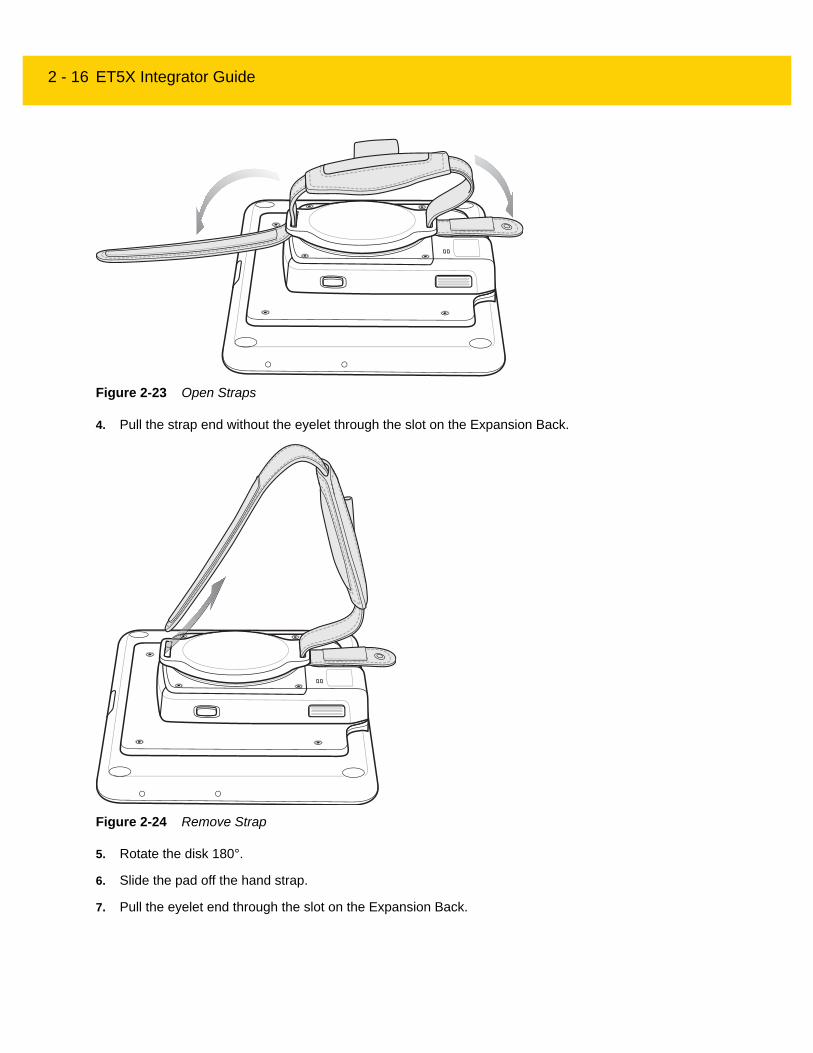
Figure 2-23 Open Straps
4. Pull the strap end without the eyelet through the slot on the Expansion Back.
Figure 2-24 Remove Strap
5. Rotate the disk 180°.
6. Slide the pad off the hand strap.
7. Pull the eyelet end through the slot on the Expansion Back.

Accessories 2 - 17
Figure 2-25 Pull Eyelet End
8. Remove pad from new replacement hand strap.
9. Rotate the disk so that one of the slots is aligned with the Power Pack opening.
10. Feed the new hand strap through the slot at the Power Pack opening.
Figure 2-26 Feed New Strap
11. Slide pad onto hand strap with the stylus holder facing up.
EyeletHook
Material
Hook Material
Power Pack Opening
Hand Strap Disk
Disk Slot
Disk Slot

2 - 18 ET5X Integrator Guide
12. Fold the eyelet end of the strap up and press hook and loop material together.
Figure 2-27 Secure Eyelet End
13. Rotate disk 180° so that the empty slot is aligned with the Power Pack opening.
14. Feed strap through the slot.
Figure 2-28 Feed Strap
15. Fold the end of the strap up and press hook and loop material together.
Stylus Holder
Pad

Accessories 2 - 19
Figure 2-29 Secure Strap

2 - 20 ET5X Integrator Guide

CHAPTER 3 SOFTWARE
IntroductionThis chapter provides instructions on how to reset and update the tablet, and to install applications.
Factory ResetRestores Windows to original factory settings without deleting any of your personal files, apps installed from Windows Store, or personalization settings.
To restore the ET5X:
1. Swipe-in from the right edge of the display to access Charms.
2. Touch Settings > Change PC settings > Update and recovery > Recovery.
3. Under Refresh your PC without affecting your files, touch Get started.
4. Read the warning and touch Next.
System UpdatesSystem Update packages can contain either partial or complete updates for the operating system. Zebra distributes the System Update packages on the Support Central web site.
1. Download the system update package:
NOTE Apps installed from the Windows Store are automatically reinstalled after the refresh is complete. Apps installed from sources other than the Windows Store are removed and have to be manually installed. A list of apps removed during this process is created on the desktop after the process is complete.
After refreshing the ET5X, apps installed from the Window Store are automatically reinstalled using a mobile broadband or Wi-Fi internet connection. To minimize data consumption over your broadband connection and prevent excessive charges from your carrier, it is highly recommended that you turn off the mobile broadband connection and reinstall the apps using a Wi-Fi connection. For more information on turning off the mobile broadband connection, see Mobile broadband Setting.
3 - 2 ET5X Integrator Guide
a. Go to the Support Central web site, http://www.zebra.com/support.
b. Download the appropriate System Update package to a host computer.
2. Extract the zip file to a folder on the host computer.
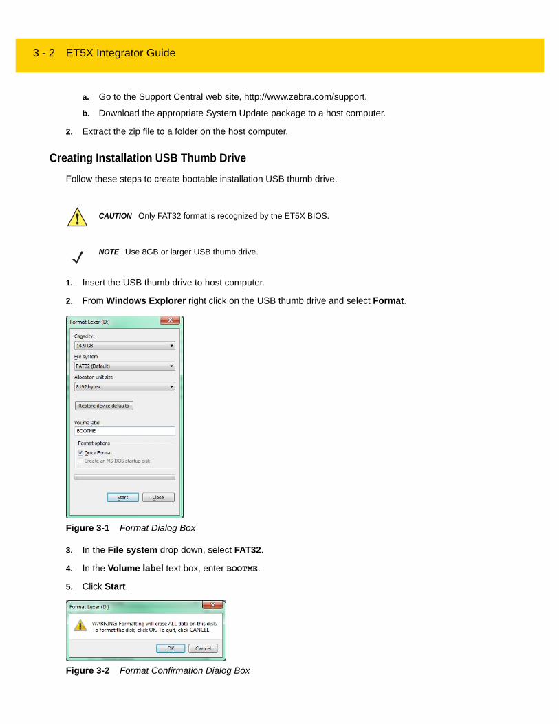
Creating Installation USB Thumb DriveFollow these steps to create bootable installation USB thumb drive.
1. Insert the USB thumb drive to host computer.
2. From Windows Explorer right click on the USB thumb drive and select Format.
Figure 3-1 Format Dialog Box
3. In the File system drop down, select FAT32.
4. In the Volume label text box, enter BOOTME.
5. Click Start.
Figure 3-2 Format Confirmation Dialog Box
CAUTION Only FAT32 format is recognized by the ET5X BIOS.
NOTE Use 8GB or larger USB thumb drive.
Software 3 - 3
6. Click OK.
Figure 3-3 Format Complete Dialog Box
7. Click OK.
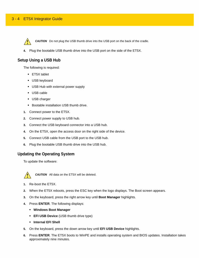
8. Using Windows Explorer, copy the contents from the System Update package onto the thumb drive.
Figure 3-4 Copy Boot Files to Thumb Drive
9. Ensure that all the files copied successfully.
10. On the host computer, unmount the thumb drive.
Setup Using Communication DockThe following is required:
• ET5X tablet
• USB keyboard
• Communication Dock with power supply.
• Bootable installation USB thumb drive.
1. Connect power to the Communication Dock.
2. Insert the ET5X into the Communication Dock.
3. Plug the USB keyboard connector into a USB port on the back of the dock.
CAUTION Carefully follow the host computer’s instructions to unmount the thumb drive and disconnect the drive correctly to avoid losing information.
3 - 4 ET5X Integrator Guide
4. Plug the bootable USB thumb drive into the USB port on the side of the ET5X.
Setup Using a USB HubThe following is required:
• ET5X tablet
• USB keyboard
• USB Hub with external power supply
• USB cable
• USB charger
• Bootable installation USB thumb drive.
1. Connect power to the ET5X.
2. Connect power supply to USB hub.
3. Connect the USB keyboard connector into a USB hub.
4. On the ET5X, open the access door on the right side of the device.
5. Connect USB cable from the USB port to the USB hub.
6. Plug the bootable USB thumb drive into the USB hub.
Updating the Operating SystemTo update the software:
1. Re-boot the ET5X.
2. When the ET5X reboots, press the ESC key when the logo displays. The Boot screen appears.
3. On the keyboard, press the right arrow key until Boot Manager highlights.
4. Press ENTER. The following displays:
• Windows Boot Manager
• EFI USB Device (USB thumb drive type)
• Internal EFI Shell
5. On the keyboard, press the down arrow key until EFI USB Device highlights.
6. Press ENTER. The ET5X boots to WinPE and installs operating system and BIOS updates. Installation takes approximately nine minutes.
CAUTION Do not plug the USB thumb drive into the USB port on the back of the cradle.
CAUTION All data on the ET5X will be deleted.
Software 3 - 5
When complete, the device boots and the Windows setup screen appears.
7. Enter all the information to create a profile.
The Windows Home screen appears.
8. Open Windows Desktop.
9. In the Taskbar, touch the Devices and Printers icon.
10. Select Eject drive.
11. After the message Safe To Remove Hardware appears, remove the thumb drive from the tablet.
12. Swipe from the right.
13. Touch Settings.
14. Touch Power > Restart.
Checking VersionsUse the following to check the versions for:
• ULPMC
• BIOS
• Operating system.
Check ULPMC VersionTo check the current ULPMC version:
1. Setup tablet with USB hub or cradle. See Setup Using Communication Dock on page 3-3 or Setup Using a USB Hub on page 3-4.
2. Reboot the ET5X.
3. When the logo appears, press ESC key on keyboard.
4. Use the keyboard arrow keys too select SCU.
5. Press Enter key. The BIOS screen appears.
3 - 6 ET5X Integrator Guide
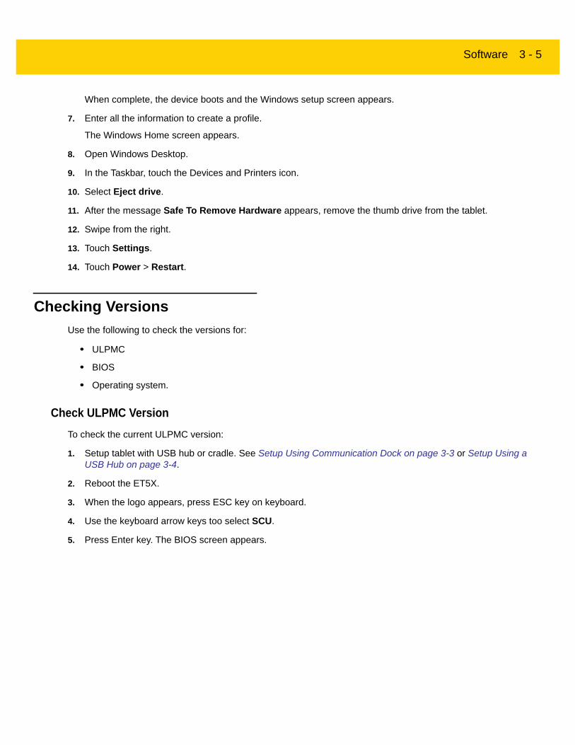
Figure 3-5 BIOS Screen
6. Check ULPMC FW field. Displays the version number:
e.g. ULPMC FW 64 (3) = ULPMC_64_03.
7. Press ESC key to exit the BIOS screen.
Check BIOS VersionTo check the current version of the BIOS:
1. On the Windows screen, swipe from the right.
2. Select Search.
3. In the Search text box, type cmd and select Command Prompt.
4. In the Command window, type msinfo32.
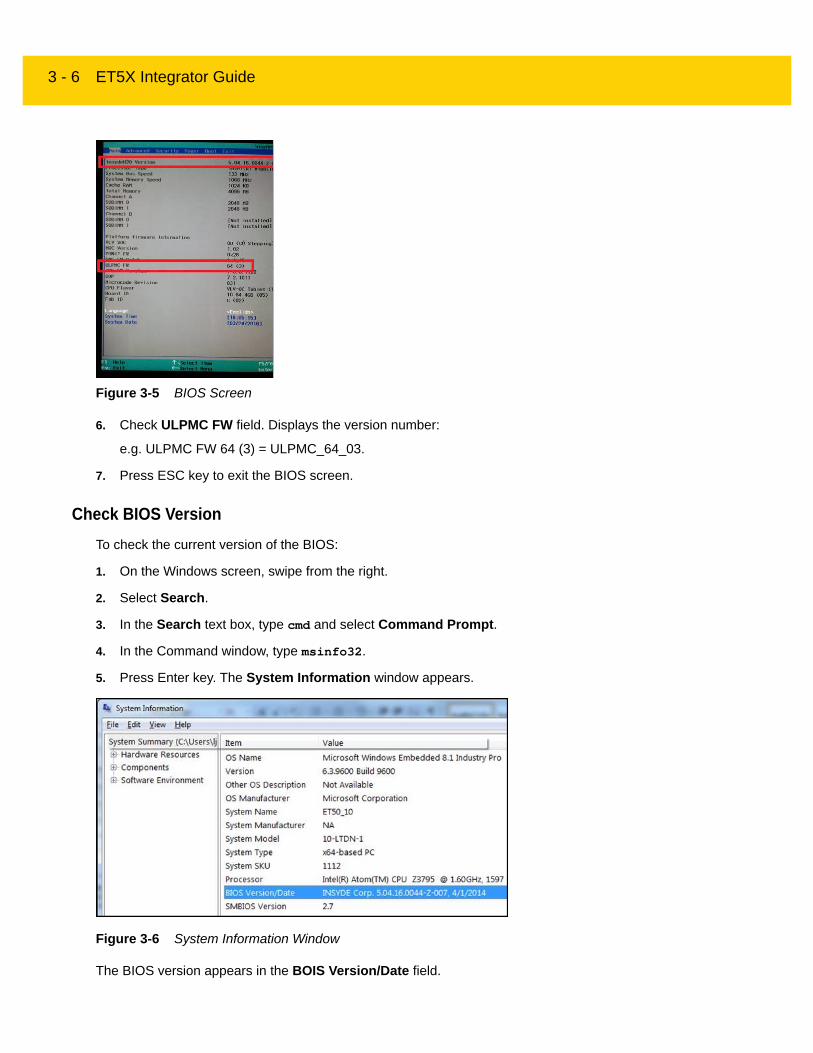
5. Press Enter key. The System Information window appears.
Figure 3-6 System Information Window
The BIOS version appears in the BOIS Version/Date field.

Software 3 - 7
Check Operating System VersionTo check the current operating system version:
1. On the Windows screen, swipe from the right.
2. Touch Search icon.
3. In the Search text box, type cmd.
4. Select Command Prompt.
5. In the Command Prompt window, type: reg query HKLM\Software\ReleaseInfo.
Figure 3-7 Release Information
The release version appears on the screen: WIN8-ZEBRA-R1.0-010-x64.
Downgrade to Previous Operating System Version
Downgrading to previous versions of operating system is a two step process. First, downgrade the ULPMC firmware. See Downgrading ULPMC via EFI Shell on page 3-7. Second, load the desired target operating system version.
If you wish to downgrade from WIN8-ZEBRA-R1.0-0010-x64 to WIN8-ZEBRA-R1.0-007-x64, first flash the ULPMC for WIN8-ZEBRA-R1.0-007 (ULPMC_64_03) before loading WIN8-ZEBRA-R1.0-007-x64.
Downgrading ULPMC via EFI Shell
• For flashing though EFI-Shell, prepare a USB thumb drive with the desired target release as per instructions in Creating Installation USB Thumb Drive on page 3-2.
• Locate the correct ULPMC version for the target release. Goto the Zebra Support Central web site.
1. Plug the installation USB thumb drive into the USB hub or USB port on the side of the tablet.
CAUTION Failure to follow these steps might result into image corruption.
Automatic downgrade of ULPMC is not possible.
NOTE Loading the ULPMC file is only required during the downgrade process. For example, downgrading from WIN8-ZEBRA-R1.0-0010-x64 to WIN8-ZEBRA-R1.0-007-x64.

3 - 8 ET5X Integrator Guide
2. Reboot the device.
3. When the logo appears, press ESC button on the keyboard. Device boots into BIOS.
4. On the keyboard, press the right arrow key until Boot Manager highlights.
5. Press ENTER. The following displays:
• Windows Boot Manager
• EFI USB Device (USB thumb drive type)
• Internal EFI Shell
6. On the keyboard, press the down arrow key until Internal EFI Shell highlights.
7. Press Enter.
8. Type fs1: and press Enter.
9. For Sierra Wireless modem, type ULPMC_FW_UPDATE_64_signed.efi /f Aava_ULPMC_XX_XX_XX.txt /sm.
For Huawai modem, type ULPMC_FW_UPDATE_64_signed.efi /f Aava_ULPMC_XX_XX_XX.txt.
(Where XX_XX_XX is the current firmware version with 64-bit BIOS use).
For example: ULPMC_FW_UPDATE_64_signed.efi /f Aava_ULPMC_64_03_ZE.txt
10. Press Enter.
11. Check that firmware update is completed successfully.
Downgrade Operating SystemTo downgrade the software:
1. Re-boot the ET5X.
2. When the ET5X reboots, press the ESC key when the logo displays. The Boot screen appears.
3. On the keyboard, press the right arrow key until Boot Manager highlights.
4. Press ENTER. The following displays:
• Windows Boot Manager
• EFI USB Device (USB thumb drive type)
• Internal EFI Shell
5. On the keyboard, press the down arrow key until EFI USB Device highlights.
6. Press ENTER. The ET5X boots to WinPE and installs operating system and BIOS updates. Installation takes approximately nine minutes.
NOTE To determine modem type see Determining Modem Type on page 3-9.
CAUTION All data on the ET5X will be deleted.
Software 3 - 9
When complete, the device boots and the Windows setup screen appears.
7. Enter all the information to create a profile.
The Windows Home screen appears.
8. Open Windows Desktop.
9. In the Taskbar, touch the Devices and Printers icon.
10. Select Eject drive.
11. After the message Safe To Remove Hardware appears, remove the thumb drive from the tablet.
12. Swipe from the right.
13. Touch Settings.
14. Touch Power > Restart.
Determining Modem TypeTo determine the type of modem in the ET5X:
1. On the Windows screen, swipe from the right.
2. Touch Settings.
3. Touch Change PC settings.
4. Touch Network.
5. Under Mobile broadband touch the modem name. The manufacturer and model appear under Properties.
Data Capture Application DevelopmentFor scanner resources, go to the Zebra Barcode Scanner Drivers and Utilities web page, https://www.zebra.com/us/en/products/software/scanning-systems/scanner-drivers-and-utilities.html.
Application InstallationInstall programs from the Internet, or a network.
Install from the InternetMake sure you trust the publisher of the app and the website that's offering it.
In your web browser, tap or click the link to the app. To install it now, tap or click Open or Run, and then follow the instructions on your screen. To install the app later, tap or click Save or Save as to download it.
Install from a networkAsk your network administrator for help installing applications from company network.

3 - 10 ET5X Integrator Guide
CHAPTER 4 MAINTENANCE AND TROUBLESHOOTING
IntroductionThis chapter includes instructions on cleaning and storing the ET5X, battery maintenance and provides troubleshooting solutions for potential problems during ET5X operations.
Maintaining the ET5XFor trouble-free service, observe the following tips when using the ET5X:
• Protect the ET5X from temperature extremes.
• Do not store or use the ET5X in any location that is extremely dusty, damp, or wet.
• Use a soft lens cloth to clean the scan exit window of the ET5X. If the surface of the ET5X screen becomes soiled, clean it with a soft cloth moistened with a diluted window-cleaning solution. Do not use bleach or ammonia.
• Take care not to scratch the screen of the ET5X.
• The display of the ET5X contains glass. Take care not to drop the ET5X or subject it to strong impact.
Battery Safety Guidelines• The area in which the ET5X units are charged should be clear of debris and combustible materials or
chemicals. Particular care should be taken where the device is charged in a non-commercial environment.
• Do not use incompatible batteries and chargers. If you have any questions about the compatibility of a battery or a charger, contact Zebra Support. See Service Information on page xi for contact information.
• Do not crush, puncture, or place a high degree of pressure on the battery.
• Follow battery usage, storage, and charging guidelines found in the ET5X Quick Reference Guide.
• Improper battery use may result in a fire, explosion, or other hazard.
• To charge the mobile device battery, the battery and charger temperatures must be between +32°F and +104°F (0°C and +40°C)

4 - 2 ET5X Integrator Guide
• Do not disassemble or open, crush, bend or deform, puncture, or shred.
• Severe impact from dropping any battery-operated device on a hard surface could cause the battery to overheat.
• Do not short circuit a battery or allow metallic or conductive objects to contact the battery terminals.
• Do not modify or remanufacture, attempt to insert foreign objects into the battery, immerse or expose to water or other liquids, or expose to fire, explosion, or other hazard.
• Do not leave or store the equipment in or near areas that might get very hot, such as in a parked vehicle or near a radiator or other heat source. Do not place battery into a microwave oven or dryer.
• Battery usage by children should be supervised.
• Please follow local regulations to promptly dispose of used re-chargeable batteries.
• Do not dispose of batteries in fire.
• Seek medical advice immediately if a battery has been swallowed.
• In the event of a battery leak, do not allow the liquid to come in contact with the skin or eyes. If contact has been made, wash the affected area with large amounts of water and seek medical advice.
• If you suspect damage to your equipment or battery, call Customer Support to arrange for inspection. See Service Information on page xi for contact information.
Cleaning
Materials Required• Alcohol wipes
• Lens tissue
• Cotton tipped applicators
• Isopropyl alcohol
• Can of compressed air with a tube.
Cleaning the ET5X
Housing
Using the alcohol wipes, wipe the housing.
CAUTION Always wear eye protection.
Read warning label on compressed air and alcohol product before using.
If you have to use any other solution for medical reasons please contact Zebra for more information.
WARNING! Avoid exposing this product to contact with hot oil or other flammable liquids. If such exposure occurs, unplug the device and clean the product immediately in accordance with these guidelines.

Maintenance and Troubleshooting 4 - 3
Display
The display can be wiped down with the alcohol wipes, but care should be taken not to allow any pooling of liquid around the edges of the display. Immediately dried the display with a soft, non-abrasive cloth to prevent streaking.
Power Connector
1. Remove the main battery from ET5X.
2. Dip the cotton portion of the cotton tipped applicator in isopropyl alcohol.
3. Repeat at least three times.
4. Use the cotton tipped applicator dipped in alcohol to remove any grease and dirt near the connector area.
5. Use a dry cotton tipped applicator and repeat steps 3 through 6.
6. Spray compressed air on the connector area by pointing the tube/nozzle about ½ inch away from the surface.
7. Inspect the area for any grease or dirt, repeat if required.
Cleaning Cradle ConnectorsUse this procedure to clean the connectors on a cradle:
1. Remove power from the cradle.
2. Dip the cotton portion of the cotton tipped applicator in isopropyl alcohol.
3. Rub the cotton portion of the cotton tipped applicator along the pins of the connector. Slowly move the applicator back-and-forth from one side of the connector to the other. Do not let any cotton residue on the connector.
4. All sides of the connector should also be rubbed with the cotton tipped applicator.
5. Spray compressed air in the connector area by pointing the tube/nozzle about ½ inch away from the surface.
6. Ensure that there is no lint left by the cotton tipped applicator, remove lint if found.
7. If grease and other dirt can be found on other areas of the cradle, use lint free cloth and alcohol to remove.
8. Allow at least 10 to 30 minutes (depending on ambient temperature and humidity) for the alcohol to air dry before applying power to cradle.
If the temperature is low and humidity is high, longer drying time is required. Warm temperature and dry humidity requires less drying time.
Cleaning Expansion Back ConnectorsUse this procedure to clean the connectors on an Expansion Back:
1. Remove the Expansion Back from the ET5X.
CAUTION Do not point nozzle at yourself and others, ensure the nozzle or tube is away from your face.
CAUTION Do not point nozzle at yourself and others, ensure the nozzle or tube is pointed away from your face.

4 - 4 ET5X Integrator Guide
2. Dip the cotton portion of the cotton tipped applicator in isopropyl alcohol.
3. Rub the cotton portion of the cotton tipped applicator along the pins of the connector. Slowly move the applicator back-and-forth from one side of the connector to the other. Do not let any cotton residue on the connector.
4. Spray compressed air in the connector area by pointing the tube/nozzle about ½ inch away from the surface.
5. Ensure that there is no lint left by the cotton tipped applicator, remove lint if found.
6. If grease and other dirt can be found on other areas of the Expansion Back, use lint free cloth and alcohol to remove.
7. Allow at least 10 to 30 minutes (depending on ambient temperature and humidity) for the alcohol to air dry before installing the Expansion Back.
If the temperature is low and humidity is high, longer drying time is required. Warm temperature and dry humidity requires less drying time.
Cleaning FrequencyThe cleaning frequency is up to the customer’s discretion due to the varied environments in which the ET5X units are used. They may be cleaned as frequently as required. However when used in dirty environments it may be advisable to periodically clean the scanner exit window to ensure optimum scanning performance.
CAUTION Do not point nozzle at yourself and others, ensure the nozzle or tube is pointed away from your face.
Maintenance and Troubleshooting 4 - 5
Troubleshooting
ET5X
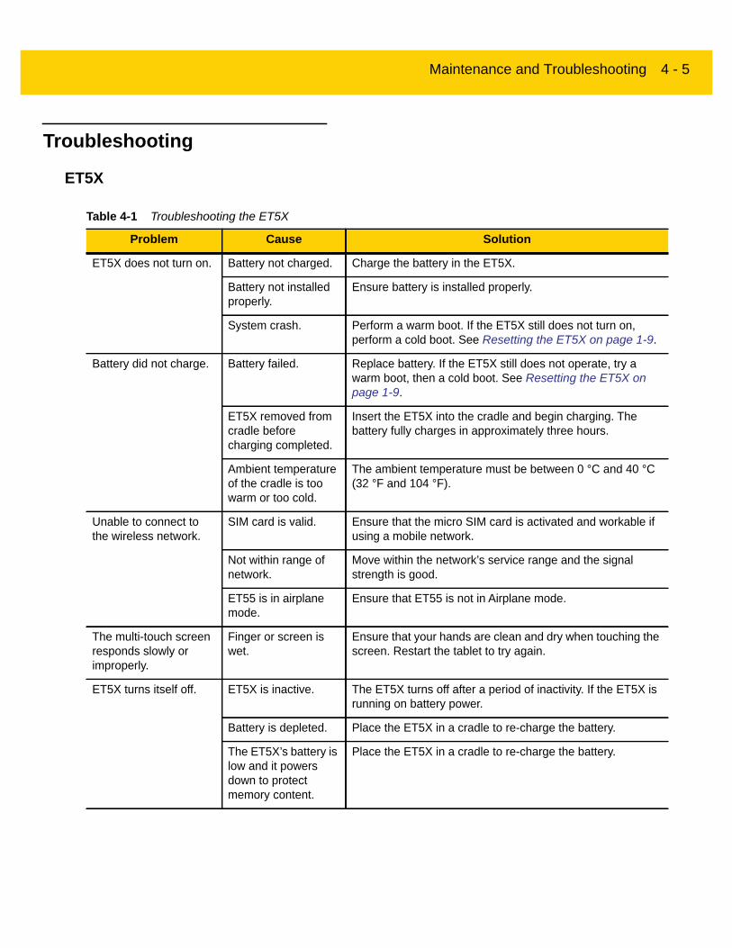
Table 4-1 Troubleshooting the ET5X
Problem Cause Solution
ET5X does not turn on. Battery not charged. Charge the battery in the ET5X.
Battery not installed properly.
Ensure battery is installed properly.
System crash. Perform a warm boot. If the ET5X still does not turn on, perform a cold boot. See Resetting the ET5X on page 1-9.
Battery did not charge. Battery failed. Replace battery. If the ET5X still does not operate, try a warm boot, then a cold boot. See Resetting the ET5X on page 1-9.
ET5X removed from cradle before charging completed.
Insert the ET5X into the cradle and begin charging. The battery fully charges in approximately three hours.
Ambient temperature of the cradle is too warm or too cold.
The ambient temperature must be between 0 °C and 40 °C (32 °F and 104 °F).
Unable to connect to the wireless network.
SIM card is valid. Ensure that the micro SIM card is activated and workable if using a mobile network.
Not within range of network.
Move within the network’s service range and the signal strength is good.
ET55 is in airplane mode.
Ensure that ET55 is not in Airplane mode.
The multi-touch screen responds slowly or improperly.
Finger or screen is wet.
Ensure that your hands are clean and dry when touching the screen. Restart the tablet to try again.
ET5X turns itself off. ET5X is inactive. The ET5X turns off after a period of inactivity. If the ET5X is running on battery power.
Battery is depleted. Place the ET5X in a cradle to re-charge the battery.
The ET5X’s battery is low and it powers down to protect memory content.
Place the ET5X in a cradle to re-charge the battery.

4 - 6 ET5X Integrator Guide
Charge Only Cradle
Communication and Charging Cradles
Table 4-2 Troubleshooting the Charge only Cradle
Symptom Possible Cause Solution
ET5X battery is not charging.
ET5X was removed from cradle or cradle was unplugged from AC power.
Ensure cradle is receiving power. Ensure ET5X is seated correctly. Confirm main battery is charging. The battery fully charges in approximately three hours.
Battery is faulty. Verify that other batteries charge properly. If so, replace the faulty battery.
The ET5X is not fully seated in the cradle.
Remove and re-insert the ET5X into the cradle, ensuring it is firmly seated.
Ambient temperature of the cradle is too warm or too cold.
Move the cradle to an area where the ambient temperature is between 0 °C and 40 °C (32 °F and 104 °F).
Table 4-3 Troubleshooting the Communication and Charging Cradles
Symptom Possible Cause Solution
ET5X battery is not charging.
ET5X was removed from cradle or cradle was unplugged from AC power.
Ensure cradle is receiving power. Ensure ET5X is seated correctly. Confirm main battery is charging. The battery fully charges in approximately three hours.
Battery is faulty. Verify that other batteries charge properly. If so, replace the faulty battery.
The ET5X is not fully seated in the cradle.
Remove and re-insert the ET5X into the cradle, ensuring it is firmly seated.
Ambient temperature of the cradle is too warm or too cold.
Move the cradle to an area where the ambient temperature is between 0 °C and 40 °C (32 °F and 104 °F).
During communication, no data transmits, or transmitted data was incomplete.
ET5X removed from cradle during communications.
Replace ET5X in cradle and retransmit.
Incorrect cable configuration.
Ensure that the correct cable configuration.

Maintenance and Troubleshooting 4 - 7
Expansion Backs
ET5X does not lock into cradle.
Access cover closed. Open ET5X access cover and re-insert ET5X onto cradle.
ET5X with Rugged Frame and IO Adapter does not mate with Communication and Charging Cradle.
Use Rugged Communication and Charging Cradle.
Table 4-3 Troubleshooting the Communication and Charging Cradles (Continued)
Symptom Possible Cause Solution
Table 4-4 Troubleshooting the Expansion Backs
Symptom Possible Cause Solution
Aiming laser does not display when pressing trigger.
On 8” tablet, did not remove rubber gasket during installation.
See system administrator to re-install Expansion Back.
ET5X is in suspend mode.
Press power button to wake the tablet.
Battery is low. If the scanner stops emitting a laser beam upon a trigger press, check the battery level. When the battery is low, the scanner shuts off before the ET5X low battery condition notification. Note: If the scanner is still not reading symbols, contact system administrator.
Laser comes on, but scanner does not decode the bar code.
ET5X is not programmed for the bar code.
Ensure the ET5X is programmed to read the type of bar code being scanned.
Unreadable bar code. Check the symbol to ensure it is not defaced. Try scanning another bar code of the same type.
Distance between exit window and bar code is incorrect.
Move the ET5X within proper scanning range.
Scanning application is not loaded.
Load a scanning application. See the system administrator.

4 - 8 ET5X Integrator Guide

APPENDIX A SPECIFICATIONS
Technical SpecificationsThe following tables summarize the ET5X’s intended operating environment and general technical hardware specifications.
ET5XThe following table summarizes the ET5X’s intended operating environment.
Table A-1 Technical Specifications
Item Description
Physical and Environmental Characteristics
Dimensions 8” Configuration:228 mm W x 150 mm H x 12.5 mm D (9.0 in. L x 5.9 in. W x 0.5 in. H)10” Configuration:(269 mm W x 181 mm H x 12.5 mm D)10.6 in. L x 7.1 in. W x 0.5 in. H
Weight 8” Configuration:555 g (1.2 lbs)10” Configuration:750 g (1.55 lbs)
Display 8” Configuration:8.3 in (diagonal) 1920 x 1200 WUVGA with backlight10” Configuration:10.1 in (diagonal) 1920 x 1200 WUVGA with backlight
Touch panel Capacitive 10 point multi-touch
Keypad Options Virtual, Bluetooth or USB

A - 2 ET5X Integrator Guide
Expansion Integrated connector to easily add accessories.
Connectivity Docking connector: USB 3.0, HDMI, charging; rugged connector for use with rugged dock Interfaces: full-size USB2.0 connector, audio jack 3.5mm, USB (for charging)
Notification LED flash; bar code decode; camera LED indicator
Audio Stereo speakers and dual microphones (one front and one rear-facing)
Battery 8” Configuration:5,900 mAh rechargeable Smart Li-Ion; user replaceable10” Configuration:8,700 mAh rechargeable Smart Li-Ion; user replaceable
Performance Characteristics
CPU Intel quad core 2.4 GHz 64 bit
Operating System
Windows 8.1 with Connected Standby (Windows 10 ready)
Memory 4GB LPDDR3 RAM; 64 GB eMMC Flash (128 GB optional); User accessible microSDXC card slot (standard supports up to 2 TB)
Data Capture
Front Camera 2 MP 1080p full HD optimized for video collaboration and low lighting conditions
Rear Camera Bar code scanning and image capture: 8MP auto-focus camera with user controllable LED flash, illumination and aiming; captures 1D and 2D bar codes, photographs, video, signatures and documents.
Video 1080p (Full HD, 1920 x 1080), Frame rate = 30fps
Scanning Optional RS507 Hands-free ImagerOptional CS4070 ScannerOptional SE4710 8” Expansion BackOptional SE4750 8” Expansion BackOptional SE4710 10” Expansion BackOptional SE4750 10” Expansion Back
User Environment
Operating Temperature
32 °F to 122 °F (0 °C to 50 °C)
Storage Temperature
-4 °F to 140 °F (-20 °C to 60 °C)
Battery Charging Temperature
32 °F to 104 °F (0 °C to +40 °C)
Table A-1 Technical Specifications (Continued)
Item Description

Specifications A - 3
Humidity 10% to 90% RH (non condensing)
Drop Specification
Standard: 1 m (3.28 ft.) drop to concrete without rugged frameWith optional rugged frame: 1.8 m (5.9 ft.) to concrete per MIL STD 810G
Vibration Operational: random vibration 10-1000 Hz 1.9g RMS, 1 hour duration per axis.Non-operational: random vibration 10-1000Hz, 4.1 g RMS
Environmental Sealing
IP65
ESD +/-8kVdc air discharge+/-4kVdc direct discharge+/-4kVdc indirect discharge
WWAN Wireless Data Communications
Global LTE with HSPA+North America multi-carrier LTE with both Verizon (EVDO) and AT&T (HSPA+) 3G fallback
WLAN Wireless Data Communications
WLAN radio 802.11a/b/g/n/k/r. Dual band 2x2 MIMO for transmit and receive.
Output Power 100mW U.S. and International
Data Rate 802.11a: up to 54Mb per second802.11b: up to 11Mb per second802.11g: up to 54Mb per second802.11n: up to 72.2Mb per second
Frequency Range
All country dependent: 802.11a - 5 GHz; 802.11b – 2.4 GHz; 802.11g – 2.4 GHz; 802.11n – 2.4 GHz / 5 GHz
Antenna Internal diversity antenna
WLAN Security WPA2 Enterprise, 802.1x; EAP-TLS; TTLS (CHAP, MS-CHAP, MS-CHAPv2, PAP or MD5); PEAP (TLS, MSCHAPv2, EAP-GTC); LEAP, EAP-FAST (TLS, MS-CHAPv2, EAP-GTC), WPA2/AES, CCX v4, FIPS 140-2 compliant and IPv6
WPAN Wireless Data Communications
Bluetooth Class 2, Bluetooth v4.0 (Bluetooth® Smart)
Near Field Communication
P2P: ISO 18092• Reader/Writer: ISO 14443 –A-B, MIFARE, FeliCa®, ISO 15693, NFC Forum Tag Types 1 to 4• Card emulation: ISO 14443 –A-B-B’, MIFARE, FeliCa RF• Distance up to 3 cm
Sensors
Gyroscope Maintains orientation based on principles of conservation of angular momentum
Table A-1 Technical Specifications (Continued)
Item Description

A - 4 ET5X Integrator Guide
SE4710 Expansion Back Decode Range
Motion Sensor 3-axis accelerometer that enables motion-sensing applications for dynamic screen orientation and power management.
Ambient Light Sensor
Automatically adjusts display brightness, keypad and display backlight.
Electronic Compass
Independent — does not depend on GPS
Proximity Sensor Shuts down the display when placed in a case.
Peripherals and Accessories
Cradles Charge Only CradleCommunication and Charging Cradle
Printers Supports extensive line of Zebra approved printers
Printers Supports extensive line of Zebra approved printers
Rugged Frame Provides additional protection for the tablet.
Table A-1 Technical Specifications (Continued)
Item Description
Table A-2 SE4710 Decode Ranges
Bar Code Type Near Distance Far Distance
Typical Typical
4 milCode 39
3.3 in / 8.4 cm 8.8 in / 22.4 cm
5 milCode 128
2.8 in / 7.1 cm 8.2 in / 20.8 cm
5 milCode 39
2.0 in / 5.08 cm 13.5 in / 34.3 cm
5milPDF417
3.1 in / 7.9 cm 8.4 in / 21.3 cm
10 milData Matrix
2.9 in / 7.4 cm 10.1 in / 25.7 cm
*Limited by width of bar code in field of view.
Note: Photographic quality bar code at 15° tilt pitch angle under 30 fcd ambient illumination.

Specifications A - 5
SE4750 Expansion Back Decode Range
SE4750 SR Decode Ranges
100% UPCA 1.8 in / 4.6 cm* 26.0 in / 66.0 cm
20.0milCode 39
2.0 in / 5.08 cm* 30.0 in / 76.2 cm
20 milQR Code
3.2 in / 8.1 cm 15.8 in / 40.1 cm
Table A-2 SE4710 Decode Ranges (Continued)
Bar Code Type Near Distance Far Distance
Typical Typical
*Limited by width of bar code in field of view.
Note: Photographic quality bar code at 15° tilt pitch angle under 30 fcd ambient illumination.
Table A-3 SE4750 SR Decode Distances
Bar Code Type Near Distance (in, typical)
Far Distance (in, typical)
3 mil Code 39 2.8 6.2
5 mil Code 128 2.3 8.7
5 mil PDF417 3.0 8.1
6.67mil PDF417 2.2 10.6
10 mil Data Matrix 2.4 10.6
100% UPCA 1.6* 23.0
15 mil Code 128 2.4* 25.2
20.0 mil Code 39 1.6* 36.3
* Limited by width of bar code in field of view.Note: Photographic quality bar code at 18o tilt pitch angle under 30 fcd ambient illumination.

A - 6 ET5X Integrator Guide
SE4750 MR Decode Ranges
Table A-4 SE4750 MR Decode Distances
Bar Code Type Near Distance (in, typical)
Far Distance (in, typical)
5 mil Code 128 7.4 16.0
5 mil PDF417 8.1 13.1
7.5 mil Data Matrix 8.3 12.8
10 mil Data Matrix 7.0 17.0
13 mil UPCA 2.3* 38.0
15 mil Code 128 4.0* 40.0
20 mil Code 39 2.1* 54.0
100 mil Code 39 11.0 172.0
160 mil Data Matrix 11.5 138.0
* Limited by width of bar code in field of view.Note: Photographic quality bar code at 18o tilt pitch angle under 30 fcd ambient illumination.

Specifications A - 7
Accessory Specifications
Charge Only Cradle
Communication and Charging Cradle
Table A-5 Charge Only Cradle Technical Specifications
Feature Description
Dimensions Height: 7.9 cm (3.1 in.)Width: 14.2 cm (5.6 in.)Depth: 11.9 cm (4.7 in.)
Weight 550 g (19.4 oz)
Input Voltage 12 VDC
Power Consumption 60 watts
Operating Temperature 0°C to 40°C (32°F to 104°F)
Humidity 10% to 90% non-condensing
Electrostatic Discharge (ESD) +/- 8 kV air+/- 4 kV contact
Table A-6 Communication and Charging Cradle Technical Specifications
Feature Description
Dimensions Height: 7.9 cm (3.1 in.)Width: 14.2 cm (5.6 in.)Depth: 11.9 cm (4.7 in.)
Weight 550 g (19.4 oz)
Input Voltage 12 VDC
Power Consumption 60 watts
Operating Temperature 0°C to 40°C (32°F to 104°F)
Humidity 5% to 90% non-condensing
Electrostatic Discharge (ESD) +/- 8 kV air+/- 4 kV contact

A - 8 ET5X Integrator Guide
Rugged Communication and Charging Cradle
Expansion Backs
Table A-7 Rugged Communication and Charging Cradle Technical Specifications
Feature Description
Dimensions Height: 7.9 cm (3.1 in.)Width: 14.2 cm (5.6 in.)Depth: 11.9 cm (4.7 in.)
Weight 550 g (19.4 oz)
Input Voltage 12 VDC
Power Consumption 60 watts
Operating Temperature 0°C to 40°C (32°F to 104°F)
Humidity 5% to 90% non-condensing
Electrostatic Discharge (ESD) +/- 8 kV air+/- 4 kV contact
Table A-8 8” Expansion Back Technical Specifications
Feature Description
Dimensions Height: 137 mm (5.4 in.)Width: 157.5 mm (6.2 in.)Depth: 54 mm (2.1 in.)
Weight 246 g (8.7 oz)
Operating Temperature 0°C to 50°C (32°F to 122°F)
Storage Temperature -20°C to 60°C (-40°F to 158°F)
Humidity 5% to 95% non-condensing
Drop 1.2 m (4 ft) drop to plywood over concrete per MIL-STD 810G across operating temperatures with rugged frame.
Electrostatic Discharge (ESD) +/- 8 kV air+/- 4 kV contact

Specifications A - 9
Table A-9 8” SE4710 Expansion Back Technical Specifications
Feature Description
Dimensions Height: 137 mm (5.4 in.)Width: 157.5 mm (6.2 in.)Depth: 54 mm (2.1 in.)
Weight 273 g (9.6 oz)
Operating Temperature 0°C to 50°C (32°F to 122°F)
Storage Temperature -20°C to 60°C (-40°F to 158°F)
Humidity 5% to 95% non-condensing
Drop 1.2 m (4 ft) drop to plywood over concrete per MIL-STD 810G across operating temperatures with rugged frame.
Electrostatic Discharge (ESD) +/- 8 kV air+/- 4 kV contact
Table A-10 8” SE4750 Expansion Back Technical Specifications
Feature Description
Dimensions Height: 137 mm (5.4 in.)Width: 157.5 mm (6.2 in.)Depth: 54 mm (2.1 in.)
Weight 273 g (9.6 oz)
Operating Temperature 0°C to 50°C (32°F to 122°F)
Storage Temperature -20°C to 60°C (-40°F to 158°F)
Humidity 5% to 95% non-condensing
Drop 1.2 m (4 ft) drop to plywood over concrete per MIL-STD 810G across operating temperatures with rugged frame.
Electrostatic Discharge (ESD) +/- 8 kV air+/- 4 kV contact
Table A-11 10” Expansion Back Technical Specifications
Feature Description
Dimensions Height: 157.7 mm (6.2 in.)Width: 184 mm (7.2 in.)Depth: 54 mm (2.1 in.)
Weight 307 g (10.8 oz)

A - 10 ET5X Integrator Guide
Operating Temperature 0°C to 50°C (32°F to 122°F)
Storage Temperature -20°C to 60°C (-40°F to 158°F)
Humidity 5% to 95% non-condensing
Drop 1.2 m (4 ft) drop to plywood over concrete per MIL-STD 810G across operating temperatures with rugged frame.
Electrostatic Discharge (ESD) +/- 8 kV air+/- 4 kV contact
Table A-12 10” SE4710 Expansion Back Technical Specifications
Feature Description
Dimensions Height: 157.7 mm (6.2 in.)Width: 184 mm (7.2 in.)Depth: 54 mm (2.1 in.)
Weight 336.5 g (11.9 oz)
Operating Temperature 0°C to 50°C (32°F to 122°F)
Storage Temperature -20°C to 60°C (-40°F to 158°F)
Humidity 5% to 95% non-condensing
Drop 1.2 m (4 ft) drop to plywood over concrete per MIL-STD 810G across operating temperatures with rugged frame.
Electrostatic Discharge (ESD) +/- 8 kV air+/- 4 kV contact
Table A-13 10” SE4750 Expansion Back Technical Specifications
Feature Description
Dimensions Height: 157.7 mm (6.2 in.)Width: 184 mm (7.2 in.)Depth: 54 mm (2.1 in.)
Weight 336.5 g (11.9 oz)
Operating Temperature 0°C to 50°C (32°F to 122°F)
Storage Temperature -20°C to 60°C (-40°F to 158°F)
Humidity 5% to 95% non-condensing
Table A-11 10” Expansion Back Technical Specifications (Continued)
Feature Description
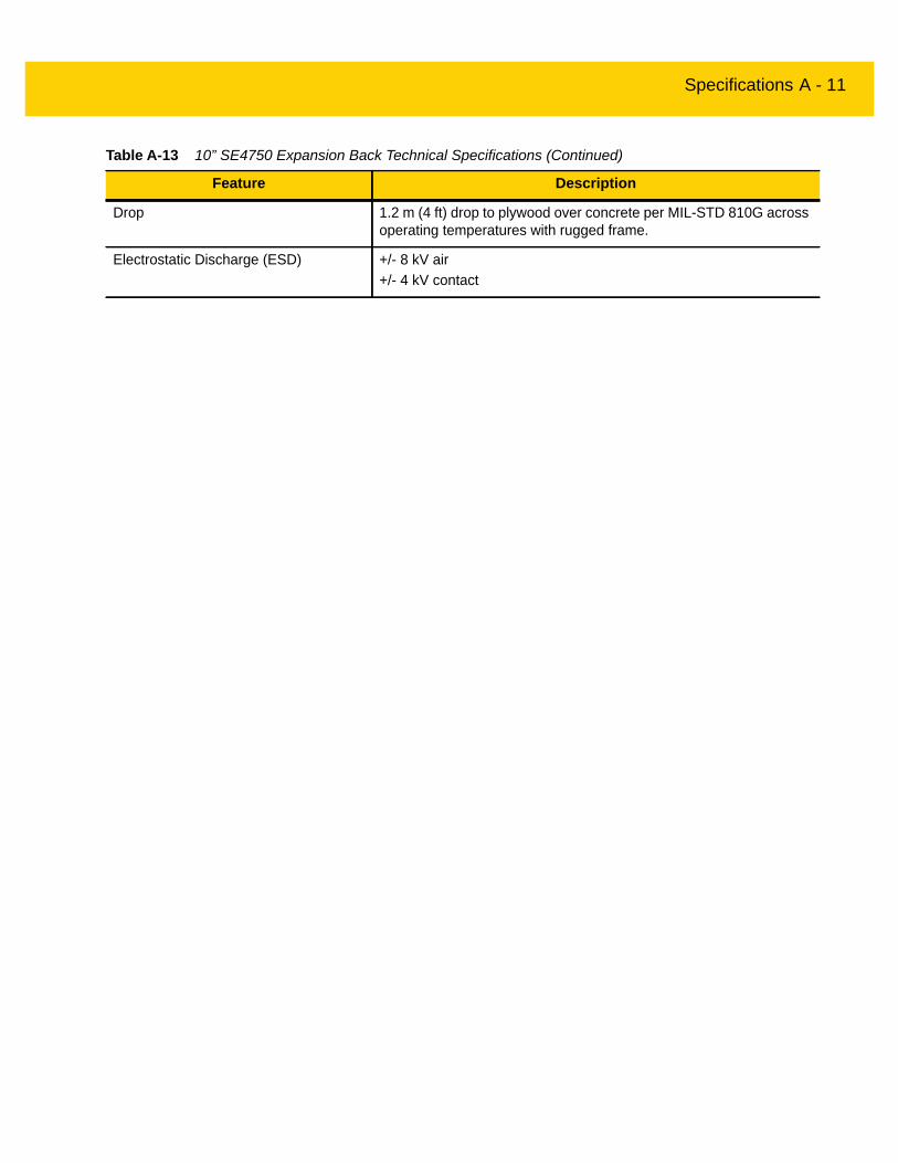
Specifications A - 11
Drop 1.2 m (4 ft) drop to plywood over concrete per MIL-STD 810G across operating temperatures with rugged frame.
Electrostatic Discharge (ESD) +/- 8 kV air+/- 4 kV contact
Table A-13 10” SE4750 Expansion Back Technical Specifications (Continued)
Feature Description

A - 12 ET5X Integrator Guide
INDEX
Numerics
Aaccessories
four slot charge only cradle . . . . . . . . . . . . . .2-6, 2-8single slot serial/USB cradle . . . . . . . . . . . . . . . . 2-4specifications . . . . . . . . . . . . . . . . . . . . . . . . . . . A-7
Bbattery charging temperature . . . . . . . . . . . . . . . . . . A-2bullets . . . . . . . . . . . . . . . . . . . . . . . . . . . . . . . . . . . . . .xi
Ccleaning . . . . . . . . . . . . . . . . . . . . . . . . . . . . . . . . . . . 4-1configuration . . . . . . . . . . . . . . . . . . . . . . . . . . . . . . . 1-1configurations . . . . . . . . . . . . . . . . . . . . . . . . . . . . . . . .ixconventions
notational . . . . . . . . . . . . . . . . . . . . . . . . . . . . . . . . xCPU . . . . . . . . . . . . . . . . . . . . . . . . . . . . . . . . . . . . . . A-2cradles
four slot charge only . . . . . . . . . . . . . . . . . . .2-6, 2-8single slot . . . . . . . . . . . . . . . . . . . . . . . . . . . . . . 2-4
Ddata capture . . . . . . . . . . . . . . . . . . . . . . . . . . . . . . . . . .ixdecode distances . . . . . . . . . . . . . . . . . . . . . . . . A-5, A-6decode ranges . . . . . . . . . . . . . . . . . . . . . . . . . . . . . . A-4dimensions . . . . . . . . . . . . . . . . . . . . . . . . . . . . . . . . A-1display . . . . . . . . . . . . . . . . . . . . . . . . . . . . . . . . . . ix, A-1drop specification . . . . . . . . . . . . . . . . . . . . . . . . . . . . A-3
Ffour slot charge only cradle . . . . . . . . . . . . . . . . . 2-6, 2-8
Ggetting started . . . . . . . . . . . . . . . . . . . . . . . . . . . . . . 1-1
Hhumidity . . . . . . . . . . . . . . . . . . . . . . . . . . . . . . . . . . . A-3
Iinformation, service . . . . . . . . . . . . . . . . . . . . . . . . . . . .xi
Llithium-ion battery . . . . . . . . . . . . . . . . . . . . . . . . . . . 1-1
Mmain battery
installing . . . . . . . . . . . . . . . . . . . . . . . . . . . . . . . 1-1maintenance . . . . . . . . . . . . . . . . . . . . . . . . . . . . . . . 4-1memory . . . . . . . . . . . . . . . . . . . . . . . . . . . . . . . . . ix, A-2
Ooperating environment, tablet . . . . . . . . . . . . . . . . . . A-1operating system . . . . . . . . . . . . . . . . . . . . . . . . . . ix, A-2operating temperature . . . . . . . . . . . . . . . . . . . . . . . . A-2
Pparts of the tablet
front view . . . . . . . . . . . . . . . . . . . . . . . . . . . . . . 1-1

Index - 2 ET5X Integrator Guide
Rradios . . . . . . . . . . . . . . . . . . . . . . . . . . . . . . . . . . . . . . .ixrelated documents . . . . . . . . . . . . . . . . . . . . . . . . . . . . .xirelated software . . . . . . . . . . . . . . . . . . . . . . . . . . . . . . .xi
Ssingle slot serial/USB cradle . . . . . . . . . . . . . . . . . . . 2-4specifications . . . . . . . . . . . . . . . . . . . . . . . . . . . . . . . A-1starting the tablet . . . . . . . . . . . . . . . . . . . . . . . . . . . . 1-1storage temperature . . . . . . . . . . . . . . . . . . . . . . . . . A-2
Ttablet configuration . . . . . . . . . . . . . . . . . . . . . . . . . . 1-1technical specifications
accessories . . . . . . . . . . . . . . . . . . . . . . . . . . . . . A-7technical specifications, tablet . . . . . . . . . . . . . . . . . . A-1troubleshooting . . . . . . . . . . . . . . . . . . . . . . . . . . . . . 4-5
Uunpacking . . . . . . . . . . . . . . . . . . . . . . . . . . . . . . . . . 1-1
Wweight . . . . . . . . . . . . . . . . . . . . . . . . . . . . . . . . . . . . A-1WLAN 802.11a/b/g/n . . . . . . . . . . . . . . . . . . . . . . . . .ix, xWPAN Bluetooth . . . . . . . . . . . . . . . . . . . . . . . . . . . .ix, x

Index - 3

Index - 4 ET5X Integrator Guide


MN-002776-01 Revision A - May 2016
Zebra Technologies Corporation, Inc.3 Overlook PointLincolnshire, IL 60069, U.S.A.http://www.zebra.com
Zebra and the stylized Zebra head are trademarks of ZIH Corp., registered in many jurisdictions worldwide. All other trademarks are the property of their respective owners.
© Symbol Technologies LLC, a subsidiary of Zebra Technologies Corporation. All rights reserved.