Embed Size (px)
Citation preview

Description This series of fixed-negative-voltage monolithic integrated-circuit voltage regulators is designed to complement Series MIK7800 in a wide range of applications. These applications include on-card regulation for elimination of noise and distribution problems associated with single point regulation. Each of these regulators can deliver up to 1.5 amperes of output current. The internal current limiting and thermal shutdown features of these regulators make them essentially immune to overload. In addition to use as fixed-voltage regulators, these devices can be used with external components to obtain adjustable output voltages and current and also as the power pass element in precision regulators.
Features • 3-Terminal Regulators • Output Current Up to 1.5 A • No External Components • Internal Thermal Overload Protection • High Power Dissipation Capability • Internal Short-Circuit Current Limiting • Output Transistor Safe Area Compensation
Package information
Package TO-220
(top view)
Typical application data 1.5 A regulator When using a negative regulator, bypass capacitors are a must on both the input and output. Recommended values are 2 µF on the input and 1 µF on the output. It is considered good practice to include a 0.1 µF capacitor on the output to improve the transient response (Fig. 1). These capacitors may mylar, ceramic, or tantalum, provided that they have good high frequency characteristics.
MIK7900$VIN$Vout
2µF 0.1 Fµ1 Fµ
32
1
Figure 1. Negative Regulator
Absolute maximum ratings over operating temperature range (unless otherwise noted)
Parameter Maximum
Units
MIK7924 -40 Input voltage All others -35
V
Continuous total dissipation at 25 °C free-air temperature 2 Continuous total dissipation at (or bellow) 25 °C case temperature 15
W
Operating free-air, case, or virtual junctions temperature range 0 to 150 Storage temperature range -65 to 150 Lead temperature 3.2 mm (1/8 inch) from case for 10 seconds 260
°C
Recommended operating conditions
Parameter Min Max Units MIK7905 -7 -25 MIK7906 -8 -25 MIK7908 -10.5 -25 MIK7912 -14.5 -30 MIK7915 -17.5 -30 MIK7918 -21 -33
Input voltage VI
MIK7924 -27 -38
V
Output current, IO 1.5 A Operating virtual junction temperature, TJ 0 125 °C
Page 1 of 5
1.5 A Negative Voltage Regulator
7 9 x xE T -

Device Selection Guide
Device Output Voltage MIK7905 -5V MIK7906 -6V MIK7908 -8V MIK7912 -12V MIK7915 -15V MIK7918 -18V MIK7924 -24V
Electrical characteristics MIK7905 Electrical characteristics at specified virtual junction temperature, VI= -10V, IO = 500mA (unless otherwise noted)
MIK7905 Parameter Test Conditions* Min Typ Max
Units
25°C -4.8 -5 -5.2 Output voltage** IO= 5mA to 1A, VI= -7V to -20V, P≤15W
0°C to 125°C -4.75 -5 -5.25
V
VI= -7V to -25V 12.5 50 Input regulation VI= -8V to -12V
25°C 4 15
mV
Ripple rejection VI= -8V to -18V, f= 120Hz
0°C to 125°C 54 60 dB
IO= 5mA to 1.5A 15 100 Output regulation IO= 250mA to 750mA
25°C 5 50
mV
Temperature coefficient of output voltage IO= 5mA 0°C to 125°C -0.4 mV/°C Output noise voltage f= 10 Hz to 100 KHz 25°C 125 µV Dropout voltage IO= 1A 25°C 1.1 V Bias current 25°C 1.5 2
VI= -7V to -25V 0.15 0.5 Bias current change IO= 5mA to 1A
0°C to 125°C 0.08 0.5
mA
Peak output current 25°C 2.1 A
Electrical characteristics MIK7906 Electrical characteristics at specified virtual junction temperature, VI= -11V, IO = 500mA (unless otherwise noted)
MIK7906 Parameter Test Conditions* Min Typ Max
Units
25°C -5.75 -6 -6.25 Output voltage** IO= 5mA to 1A, VI= -8V to -21V, P≤15W
0°C to 125°C -5.7 -6 -6.3
V
VI= -8V to -25V 12.5 120 Input regulation VI= -9V to -13V
25°C 4 60
mV
Ripple rejection VI= -9V to -19V, f= 120Hz
0°C to 125°C 54 60 dB
IO= 5mA to 1.5A 15 120 Output regulation IO= 250mA to 750mA
25°C 5 60
mV
Temperature coefficient of output voltage IO= 5mA 0°C to 125°C -0.4 mV/°C Output noise voltage f= 10 Hz to 100 KHz 25°C 150 µV Dropout voltage IO= 1A 25°C 1.1 V Bias current 25°C 1.5 2
VI= -8V to -25V 0.15 1.3 Bias current change IO= 5mA to 1A
0°C to 125°C 0.08 0.5
mA
Peak output current 25°C 2.1 A * Pulse testing techniques are used to maintain the junction temperature as close to the ambient temperature as possible. Thermal
effects must be taken into account separately. ** This specification applies only for dc power dissipation permitted by absolute maximum ratings.
Page 2 of 5
1.5 A Negative Voltage Regulator
7 9 x xE T -

Electrical characteristics MIK7908 Electrical characteristics at specified virtual junction temperature, VI= -14V, IO = 500mA (unless otherwise noted)
MIK7908 Parameter Test Conditions* Min Typ Max
Units
25°C -7.7 -8 -8.3 Output voltage** IO= 5mA to 1A, VI= -10.5V to -23V, P≤15W
0°C to 125°C -7.6 -8 -8.4
V
VI= -10.5V to -25V 12.5 160 Input regulation VI= -11V to -17V
25°C 4 80
mV
Ripple rejection VI= -11.5V to -21.5V, f= 120Hz
0°C to 125°C 54 60 dB
IO= 5mA to 1.5A 15 160 Output regulation IO= 250mA to 750mA
25°C 5 80
mV
Temperature coefficient of output voltage IO= 5mA 0°C to 125°C -0.6 mV/°C Output noise voltage f= 10Hz to 100 KHz 25°C 200 µV Dropout voltage IO= 1A 25°C 1.1 V Bias current 25°C 1.5 2
VI= -10.5V to -25V 0.15 1 Bias current change IO= 5mA to 1A
0°C to 125°C 0.08 0.5
mA
Peak output current 25°C 2.1 A
Electrical characteristics MIK7912 Electrical characteristics at specified virtual junction temperature, VI= -19V, IO = 500mA (unless otherwise noted)
MIK7912 Parameter Test Conditions* Min Typ Max
Units
25°C -11.5 -12 -12.5 Output voltage** IO= 5mA to 1A, VI= -14.5V to -27V, P≤15W
0°C to 125°C -11.4 -12 -12.6
V
VI= -14.5V to -30V 5 80 Input regulation VI= -16V to -22V
25°C 3 30
mV
Ripple rejection VI= -15V to -25V, f= 120Hz
0°C to 125°C 54 60 dB
IO= 5mA to 1.5A 15 200 Output regulation IO= 250mA to 750mA
25°C 5 75
mV
Temperature coefficient of output voltage IO= 5mA 0°C to 125°C -0.8 mV/°C Output noise voltage f= 10 Hz to 100 KHz 25°C 300 µV Dropout voltage IO= 1A 25°C 1.1 V Bias current 25°C 2 3
VI= -14.5V to -30V 0.04 0.5 Bias current change IO= 5mA to 1A
0°C to 125°C 0.06 0.5
mA
Peak output current 25°C 2.1 A * Pulse testing techniques are used to maintain the junction temperature as close to the ambient temperature as possible. Thermal
effects must be taken into account separately. ** This specification applies only for dc power dissipation permitted by absolute maximum ratings.
Page 3 of 5
1.5 A Negative Voltage Regulator
7 9 x xE T -
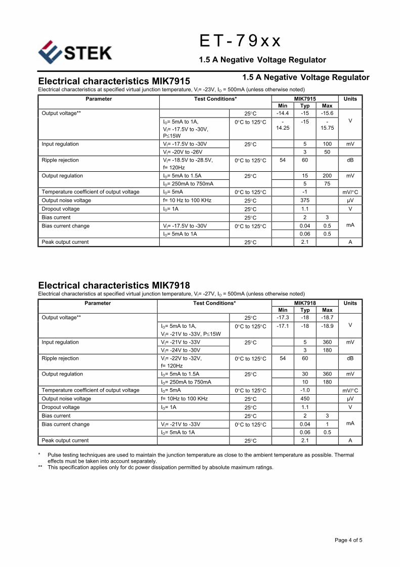
Electrical characteristics MIK7915 Electrical characteristics at specified virtual junction temperature, VI= -23V, IO = 500mA (unless otherwise noted)
MIK7915 Parameter Test Conditions* Min Typ Max
Units
25°C -14.4 -15 -15.6 Output voltage** IO= 5mA to 1A, VI= -17.5V to -30V, P≤15W
0°C to 125°C -14.25
-15 -15.75
V
VI= -17.5V to -30V 5 100 mV Input regulation VI= -20V to -26V
25°C 3 50
Ripple rejection VI= -18.5V to -28.5V, f= 120Hz
0°C to 125°C 54 60 dB
IO= 5mA to 1.5A 15 200 Output regulation IO= 250mA to 750mA
25°C 5 75
mV
Temperature coefficient of output voltage IO= 5mA 0°C to 125°C -1 mV/°C Output noise voltage f= 10 Hz to 100 KHz 25°C 375 µV Dropout voltage IO= 1A 25°C 1.1 V Bias current 25°C 2 3
VI= -17.5V to -30V 0.04 0.5 Bias current change IO= 5mA to 1A
0°C to 125°C 0.06 0.5
mA
Peak output current 25°C 2.1 A
Electrical characteristics MIK7918 Electrical characteristics at specified virtual junction temperature, VI= -27V, IO = 500mA (unless otherwise noted)
MIK7918 Parameter Test Conditions* Min Typ Max
Units
25°C -17.3 -18 -18.7 Output voltage** IO= 5mA to 1A, VI= -21V to -33V, P≤15W
0°C to 125°C -17.1 -18 -18.9
V
VI= -21V to -33V 5 360 Input regulation VI= -24V to -30V
25°C 3 180
mV
Ripple rejection VI= -22V to -32V, f= 120Hz
0°C to 125°C 54 60 dB
IO= 5mA to 1.5A 30 360 mV Output regulation IO= 250mA to 750mA
25°C 10 180
Temperature coefficient of output voltage IO= 5mA 0°C to 125°C -1.0 mV/°C Output noise voltage f= 10Hz to 100 KHz 25°C 450 µV Dropout voltage IO= 1A 25°C 1.1 V Bias current 25°C 2 3
VI= -21V to -33V 0.04 1 Bias current change IO= 5mA to 1A
0°C to 125°C 0.06 0.5
mA
Peak output current 25°C 2.1 A * Pulse testing techniques are used to maintain the junction temperature as close to the ambient temperature as possible. Thermal
effects must be taken into account separately. ** This specification applies only for dc power dissipation permitted by absolute maximum ratings.
Page 4 of 5
1.5 A Negative Voltage Regulator
1.5 A Negative Voltage Regulator
7 9 x xE T -

Electrical characteristics MIK7924 Electrical characteristics at specified virtual junction temperature, VI= -33V, IO = 500mA (unless otherwise noted)
MIK7924 Parameter Test Conditions* Min Typ Max
Units
25°C -23 -24 -25 Output voltage** IO= 5mA to 1A, VI= -27V to -38V, P≤15W
0°C to 125°C -22.8 -24 -25.2
V
VI= -27V to -38V 5 480 Input regulation VI= -30V to -36V
25°C 3 240
mV
Ripple rejection VI= -28V to -38V, f= 120Hz
0°C to 125°C 54 60 dB
IO= 5mA to 1.5A 85 480 Output regulation IO= 250mA to 750mA
25°C 25 240
mV
Temperature coefficient of output voltage IO= 5mA 0°C to 125°C -1 mV/°C Output noise voltage f= 10Hz to 100 KHz 25°C 600 µV Dropout voltage IO= 1A 25°C 1.1 V Bias current 25°C 2 3
VI= -27V to -38V 0.04 1 Bias current change IO= 5mA to 1A
0°C to 125°C 0.06 0.5
mA
Peak output current 25°C 2.1 A * Pulse testing techniques are used to maintain the junction temperature as close to the ambient temperature as possible. Thermal
effects must be taken into account separately. ** This specification applies only for dc power dissipation permitted by absolute maximum ratings.
Page 5 of 5
1.5 A Negative Voltage Regulator
7 9 x xE T -