Embed Size (px)
Citation preview
Journal of Engineering Science and Technology Review 7 (5) (2014) 9-11
Special Issue on Simulation of Manufacturing Technologies
Conference Article
ANSYS Simulation of Residual Strains in Butt-welded Joints
A. Atroshenko1, A. Vairis2, V. Bichkov1 and R. Nikiforov1,*
1Ufa State Aviation Technical University, Ufa, Russian Federation 2Dpt. of Mechanical Engineering, Technological Educational Institute of Crete, Heraklion 71004, Greece.
Received 11 September 2014; Accepted 29 September 2014
___________________________________________________________________________________________ Abstract
The effect of thermal-strain cycle on residual strains in thin-walled circular seams of cylindrical shells using TIG butt welds was studied. Estimates were calculated using numerical modelling. The structure was made of corrosion-resistant austenitic steels.
Keywords: TIG welding, residual strains, finite element method (FEM), concentrated and distributed heat sources __________________________________________________________________________________________
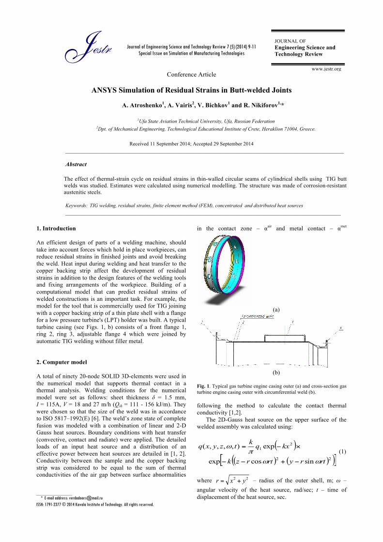
1. Introduction An efficient design of parts of a welding machine, should take into account forces which hold in place workpieces, can reduce residual strains in finished joints and avoid breaking the weld. Heat input during welding and heat transfer to the copper backing strip affect the development of residual strains in addition to the design features of the welding tools and fixing arrangements of the workpiece. Building of a computational model that can predict residual strains of welded constructions is an important task. For example, the model for the tool that is commercially used for TIG joining with a copper backing strip of a thin plate shell with a flange for a low pressure turbine's (LPT) holder was built. A typical turbine casing (see Figs. 1, b) consists of a front flange 1, ring 2, ring 3, adjustable flange 4 which were joined by automatic TIG welding without filler metal.
2. Computer model
A total of ninety 20-node SOLID 3D-elements were used in the numerical model that supports thermal contact in a thermal analysis. Welding conditions for the numerical model were set as follows: sheet thickness δ = 1.5 mm, I = 115A, V = 18 and 27 m/h (Qih = 111 - 156 kJ/m). They were chosen so that the size of the weld was in accordance to ISО 5817–1992(E) [6]. The weld’s zone state of complete fusion was modeled with a combination of linear and 2-D Gauss heat sources. Boundary conditions with heat transfer (convective, contact and radiate) were applied. The detailed loads of an input heat source and a distribution of an effective power between heat sources are detailed in [1, 2]. Conductivity between the sample and the copper backing strip was considered to be equal to the sum of thermal conductivities of the air gap between surface abnormalities
in the contact zone – αair and metal contact – αmet
(a)
(b)
Fig. 1. Typical gas turbine engine casing outer (a) and cross-section gas turbine engine casing outer with circumferential weld (b). following the method to calculate the contact thermal conductivity [1,2].
The 2D-Gauss heat source on the upper surface of the welded assembly was calculated using:
( )( ) ( )( )[ ]22
21
sincosexp
exp),,,,(
rtryrtrzk
kxqktzyxq
ωωπ
ω
−+−−
×−= (1)
where 22 yxr += – radius of the outer shell, m; ω – angular velocity of the heat source, rad/sec; t – time of displacement of the heat source, sec.
Jestr JOURNAL OF Engineering Science and Technology Review
www.jestr.org
______________ * E-mail address: [email protected] ISSN: 1791-2377 © 2014 Kavala Institute of Technology. All rights reserved.

A. Atroshenko, A. Vairis, V. Bichkov and R. Nikiforov / Journal of Engineering Science and Technology Review 7 (5) (2014) 9 - 11
10
A linear heat source has been set as the heat flow through the plane symmetry with the equation:
( )( ) ( )( )[ ]22
22
sincosexp
exp4
),,,,(
rtryrtrzk
kxahqtzyxq
ωω
ω
−+−−
×−= (2)
In this qef = q1 + q2, where qef – effective power heating of welding arc, W.
The numerical calculation of thermal deformation was based on the deformation theory of non-isothermal flow applied with the parametric design language APDL. Residual stresses in welded joints of stainless steels do not usually exceed yield strength, and do not go beyond the boundary of the Bauschinger effect [5]. The model used for plasticity accounted for the bilinear kinematic hardening (BKIN) [6], and the deformation of the part satisfied the von Mises yield criteria [5]. Thermal analysis and the scheme based of parts of welded assembly in the machinery for welding shown in Fig. 2.
(a)
(b)
Fig. 2. Temperature fields from the moving heat sources (a) and the welding drawing of the outer casing of the gas turbine engine (b).
In ANSYS / Multiphysics the base surface A the node movement was restricted for the surface of the 3D model of the x-axis, and surface B - while keeping the nodes on the corresponding surfaces of axes OZ and OY. For the locked and the fixed but adjustable flange 4 and base A respectively there was axial movement restriction applied and decompressed concentric sectors, while was carried by a pneumatic drive. Contact forces on elements were calculated using standard equations for calculating welding tooling elements [4].
3. Discussions
After calculations the required axial force on the plunger to lock welded parts was found to be Fpr = 6.4 kN, and the
required total decompressed radial force on all sectors was Fs = 18.1 kN.
(a)
(b)
Fig. 3. Radial displacement for 3D-model on y axis for welding with Qih
= 156 kJ / m, (a) and Qih = 111 kJ / m (b)
The radial displacements in the 3D-model along OY
circumferential weld ring 2 and the front flange 1 which correspond to the circumferentially welded assembly are shown in Fig. 3.
As can be seen in Fig. 3 for a maximum input heat during welding of Qih = 156 kJ / m the radial shrinkage Δrs was 0,277 mm and at Qih = 111kJ / m the shrinkage was Δrs= 0.247 mm. Thus the circumferential shrinkage of the thin shells is essentially independent of the welding conditions and, consequently, parameters of the geometry of the weld. Transverse shrinkage for welding parameters with Qih = 156 kJ / m and 111 kJ / m was found to be Δtr = 0.0229 and 0.0225 mm, respectively.
Construction of concentric sectors will affect the distribution of residual strains and will be essential, depending on the area of contact with the inner wall of the shell. The residual strains were calculated for the following modifications for securing the welded assembly (see Fig. 4): a) when the width of the zone of contact with the copper backing strip sidewall was 6 mm, radial decompressed force sectors had Fs = 18.1 kN, an axial force Fpr = 6.4 kN; b) the width of the zone of contact with the copper backing strip sidewall was 22 mm, radial decompressed force sectors Fs = 18.1 kN, axial force Fpr = 12.8 kN; c) the width of the zone of contact with the copper backing strip sidewall was 22 mm, radial decompressed force sectors Fs = 18.1 kN, axial force Fpr = 6.4 kN. Numerical analysis results were for the welding parameters - I = 115A, V = 10 m / h, l = 3 mm, Qih = 156 kJ / m.
From the numerical modeling of the welded assembly transverse shrinkage for the different fixing arrangements shown in Fig. 4 was as follows: a) Δtr = 0.247 mm; b) Δtr = 0.476 mm and c) Δtr = 0.183 mm, respectively. Increasing the width of the contact zone from 6 mm to 22 mm resulted in a more intense heat transfer in the copper backing strip and reduced shrinkage from 0.247 to 0.183 mm. At the same time the welded assembly transverse shrinkage was almost independent of heat input and increased from 0.247 to 0.476 mm only by doubling the axial force in modification (b)

A. Atroshenko, A. Vairis, V. Bichkov and R. Nikiforov / Journal of Engineering Science and Technology Review 7 (5) (2014) 9 - 11
11
(a)
(b)
(c)
Fig. 4. Different modifications for fixing the welded assembly in the machinery for welding
4. Conclusions
1. A thermal deformation model has been applied to a real case to predict the residual strain of thin-walled welded structures and shells with tight tolerances in order to identify changes in geometric dimensions and optimize the structure by choosing the most efficient arrangement for fixing the welded assembly, its build, the size of the expanding force concentric sectors and the axial preload of the welded assembly at the preparatory stage for welding.
2. Modeling residual strains of the impact of the thermal-welding cycle during TIG-welding of outer casing for a gas turbine engine showed that the magnitude of both the radial and transverse shrinkage of welds thin shells does not depend on heat input when welding in the range 111 - 156 kJ / m.
3. A significant impact on the welded assembly transverse shrinkage is exerted by a force in the axial direction in the machine for welding, which increases from 6.4 to 12.8 kN as the welded assembly transverse shrinkage changes from 0,247 to 0,476 mm respectively.
______________________________
References [1] Edfors, O., M. Sandell , J.J.Van de Beek, D. Landström, and F.
Sjöberg, An Introduction to Orthogonal Frequency Division Multiplexing, Luleå, Sweden: Luleå Tekniska Universitet, 1996.
[2] Taub, H., D. L. Schilling, and G. Saha, Taub’s Principles of Communication Systems, Tata McGraw Hill, 2010.
[3] Slar, B., Digital Communications: Fundamentals and Applications, Prentice-Hall, 2nd Edition, 2001.
[4] Bahai, A.R. S., B. R. Saltzberg, and M. Ergen, Multicarrier Digital Communications: Theory and Applications of OFDM. Springer, New York, 2004.
[5] Nee, R. V., and R. Prasad, OFDM Wireless Multimedia Communications. Norwood, MA, Artech House, 2000.
[6] R. Prasad, OFDM for Wireless Communications Systems. Artech House, 2004.
[7] Bingham, J. A. C., “Multi Carrier Modulation for Data Transmission. An idea whose time has come”, IEEE Communications Magazine, vol.28, no.5, pp. 5-14, May, 1990.
[8] ETS 300 744 - Digital Video Broadcasting (DVB); Framing structure, channel coding and modulation for Digital Terrestrial Television, (DVB-T).
[9] онов, К., Цифрово радио и телевизионно разпръскване, Диодс, София, 2011.
[10] Sadinov, S., P. Daneva, and P. Kogias, “OFDM (Orthogonal Frequency Division Multiplexing) Transmission Simulation”, International Scientific Conference Unitech 2013, Gabrovo, vol. II, pp. 121 - 126, 22 – 23 November, 2013.
[11] Pathak, N., “OFDM (Orthogonal Frequency Division Multiplexing) SIMULATION USING MATLAB”, IJERT, Vol. 1, Issue 6, pp. 1-6, August - 2012.
[12] Ghorpade, S. S., and S. V. Sankpal, “Behaviour of OFDM system using MATLAB simulation”, International Journal of Advanced Computer Research, vol. 3, pp. 67 - 71, June 2013.