Embed Size (px)
Citation preview

[umal Mekanikal, Jilid I, 1996
ESTIMATION OF SHIP MANOEUVRINGCHARACTERISTICS IN THE CONCEPTUAL DESIGN STAGE
Mohd. Rarnzan Mainal PEng MIEM MSNAME
Department of ThennoFluid
Faculty of Mechanical Engineering
Universiti Teknologi Malaysia
and
Mohd. Salim Kamil PEng MIEM
Royal Malaysian Navy
Ministry of Defence, Malaysia
ABSTRACT
In relation to the problems of tile maritime safety, the diversification in ship
types or the growth in ship sizes has enhanced the significance of
manoeuvrability as one of the fundamental performances ofships. Namely
it has become very important to predict the ship manoeuvrability at the stage
of the initial ship design process. This paper presents a mathematical model
for estimating the ship manoeuvring performance to cope with the
increasing demands for conceptual design stage evaluation ofsafety in ship
operation. The mathematical model developed can be extendedfurther to be
made applicable to various other problems such as low speed manoeuvres,
lateral shifting stopping manoeuvres.
1.0 INTRODUCTION
Manoeuvring characteristics of ships are complex phenomena which include course
keeping and turning ability. There are no simple criteria to rate the qualities of ships with
respect to these characteristics. The associated flow phenomena are complex and often
coupled to other phenomena. Course keeping in waves, for instance, is often connected to
44
[urnal Mekanikal, Jilid I, 1996
rolling motion stability. Further complications are introduced by the environment (shallow
water, bank effects, other traffic), the actual operating conditions of the ship and human
aspects.
Manoeuvring characteristics-have often been neglected during the conceptual design
phase. Recently, an increased awareness of the importance of manoeuvrability for the
safety of the ship and environment can be observed. Accidents such as with 'Herald of
Free Enterprise', in which manoeuvrability played some role, have certainly contributed to
this increased interest [14]. Recognition of the importance of knowledge on the
manoeuvring characteristics has for instance led to International Maritime Organisation
(IMO) requirements for posting 'data on the characteristics at the navigating bridge of ships.
In addition, it is expected that IMO will issue criteria for ship manoeuvrability in the near
future.
Ship operators are very familiar with bridge simulators. These simulators are very
sofisticated electronic gadgetry that allow the ship's crew to be trained at shore base on any
particular class of vessel. The bridge is simulated either in day or night time operation.,
including all the instrumentation that is usual on the ship's bridge. The bridge simulator
usually requires full scale trials to be conducted to provide manoeuvring information,
which is then fed into a computer model of that particular ship. Thus the modification of
the simulator to take allowance of a new ship type can be extremely expensive and equally
time consuming. This type of simulator is of little use to a ship designer in the early stages
of the design spiral. The designer should have a much simpler tool that allows immediate
investigation of the characteristics of the new ship design.
With this fairly simple objective, a computer aided tool has been produced that
requires only the use of a micro computer of moderate processing power. In essence this
computer aided design tool is capable of helping the designer to investigate the effect that
modifications to the ship design will have on the handling characteristics of the ship.
2.0 EQUATIONS OF MOTION
In this analysis, the ship is considered to be a rigid body, with only three degrees of
freedom, that is, surge, sway and yaw, The ship motions in the other three degrees of
freedom, roll, pitch and heave, are neglected -md not considered in this treatment. It is
convenient to describe the motions in terms of a Eulerian system of axes coincident with
45

lurnal Mekanikal, Jilid 1, 1996
amidship. This co-ordinate system is illustrated in Fig. 1 together with the basic
nomenclature used. Thus, this gives rise to the equations of motion:
Y =m(v + ur + xar)
N =Izr + mxa(v + ru)
Eqn. 1
Eqn. 2
Egn . 3
In the above equation, the terms on the right hand side describe the inertial
responses and those on the left hand side are the hydrodynamic forces and moments acting
on the ship due to the motions which are usually expressed as perturbations about a steady
ahead speed . These forces and moments are then assumed to be directly proportional to
these perturbation quantities. Details of this procedure and its limitations are given in
References [2] and [7].
0r===:===-------------------:i~
Fig. I Co-ordinate Axes System Adopted for Mathematical Modelling
46

[urnal Mekanikal, ]iLid 1, 1996
Neglecting the non-dimensional terms, Eqn. 1 to Eqn. 3 may be expressed as:
Eqn.4
Eqn.5
Eqn. 6
In all the terms in the above equations, the subscript notation refers to partial
differentials with respect to that variables. For example
X. =ax and Y _ ayu au Y-av
Expressing Eqn. 1 to Eqn. 3 in terms of the perturbation quantities and discarding
all but linear terms in order to maintain consistency with Eqns. 4, 5 and 6, the following
forms of linearised equations of motion are obtained:
(Xu - mju + XuLlu =0
(Yv - m)v + Y yV + (Yt - mXG)r + (Yr - muo)r == 0
Eqn. 7
Eqn. 8
Eqn.9
No consideration has been given in the above treatment to the forces and moments
created by rudder deflection. It is usual to assume that the rudder will give rise to a side
force and moment which are directly proportional to the rudder angle. Following the
addition of the rudder terms, Eqns. 7, 8 and 9 are more conveniently expressed in a
dimensionless form, by dividing them with .!. pU6L2 and .!. pU6L3 respectively. This2 2
results in the usual form, the linearised equations of motion used in steering and
manoeuvring
(Y'v - m' )v' + Y' y v' + (Y' r - m' x' G )r' + (Y' r - m' )r' + YB'0 =0 Eqn. 10
The dimensionless quantities in the above equations are given in Ref. (1).
47

TUrnJJI Mekanikal, Tilid 1, 1996
Although Eqns . 10 and I I expressed the linear equations of motion as pair of
simultaneous first order differential equations, where the constant coefficients are
dimensionless acceleration and velocity derivatives, it is possible to express these equations
in an alternative form. It was first shown by Nomoto [3] that these equations can be
written as a pair of decoupled second order equations as follows:
Eqn .12
Eqn.13
The terms in the above equations, and their algebraic relationships with the
acceleration and velocity derivatives are given in Appendix.
It is common practice in the analysis of trial manoeuvres, both at full scale and
with free running models, to use a more simple expression than that given in Eqns. 12 and
13. Nomoto first proposed an equation given as follows :
T' r' + r' =K' 0
3.0 MANOEUVRING CRITERIA
3.1 Turning Ability
Eqn. 14
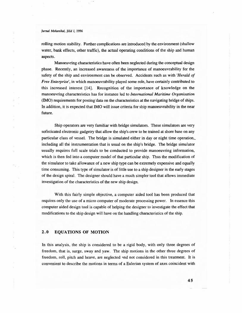
When the turning ability of a ship is mentioned, it is usually described in the context of its
turning circle as shown in Fig. 2. Measurements of the advance, transfer and diameter are
quoted as a means of quantifying the ship's inherent turning stability. However, most
ships, whether stable or unstable, tum with a circle diameter between two to three times the
length of the ship, so that the terminal turning behaviour is not a useful means of assessing
the manoeuvrability of a ship.
Before considering the turning circle, the initial turning ability of the ship will be
examined, after the application of the rudder while following a straight course. In this
way, the linear equations developed in the previous section may be used, since the
deviations from the initial steady state are still small.
48
Jurnal Mekanikal, Jilid 1, 1996
A suitable definition of turning ability can be taken as the heading angle turned
through from an initial straight course, per unit rudder angle applied, after the ship has
travelled one ship length. This situation is shown in Fig. 3 where the heading response to a
rudder movement of angle d in a time t'r, following which the rudder remains constant.
The heading response can be obtained by solving the first part of Eqns. 12 and 13 for this
rudder time history, together with zero rate and heading angle initial conditions, as follows
'l'it ) =K'[t' -(T'] +T 2 -T'3)+t'r/2
+ (T']-T'3)T'f (et'r/TI _1)e-t'/TI(T'] - T' 2 )t' r
_ (T'2 -T'3)T'~(et'r/T2_1)e-t'IT2](T'] - T' 2 )t' r
Eqn.15
Fig. 2 Turning Path of a Ship
49

[urnal Mekanikal, Jilid I, 1996
':P,o
tarr! K'o
T + O.St'r
Fig . 3 Turning Ability of a Ship
Similarly, by solving Eqns. 12 and 13 for the same rudder input,
Eqn . 16
Study of Eqns. IS and 16 confirms that both solutions tend to a similar asymptote
if:Eqn. 17
If the time for the rudder movement tends to zero, and non-dimensionalised time is
set to t =1, (which is equivalent to moving one ship length), then Eqns, 6 and 7 become:
'\lI (t ) =K' lt' - (1- (T' + T' - T' ) + (T'l - T'3)T'f T' e-t'IT\(5 I 2 3 (T'l - T' 2 )t' r \
_ (T' 2 - T' 3)T'~ T' e-I'/T'2]
(T' \ - T' 2 )t' r 2
50

I;mllll Melamilail, lilid I, 1996
and
Eqn. 18
Non-bin [2] first introduced the idea of a turning index and used Eqn. 18 to denote
what he termed the 'P' number. This is the heading change per unit rudder angle for one
ship length travelled, described in terms of the Nomoto indices K' and T. Norrbin
suggested a tentative value of P > 0.3 for vessels smaller than the tanker. A value of P =0.3 is equivalent to a 10° heading change in one ship length, when the rudder is placed
hard over in excess of 30°. Equation 9 may be expanded into the form
and when T is large this reduces to
K'P=:
2T'
3.2 Dynamic Stability
Eqn. 19
Eqn.20
For a linear dynamic system to be stable it is necessary for the roots of the characteristic
equations to be negative. In most ship manoeuvring problems, these roots are usually real
so that this requirement is satisfied if the time constants are positive. The condition for
stability therefore reduces to :
Y'v (N' r - m' x' G ) - N' v (Y' r - m' ) > 0
and may also be expressed as
N' -m'x' N'r G>_y
Y'r-m' v ;
Eqn.2l
Eqn.22
51

[urnal Mekanikal, Jilid I, 1996
This latter inequality is useful in defining the requirement for dynamic stability. It
simply indicates that the centre of pressure in pure yaw should be ahead of the centre
pressure in pure sway if the ship is to be dynamically stable .
4.0 ESTIMATION OF DERIVATIVES
At the present time , the most reliable method of determining the numerical values of the
velocity and acceleration derivatives is by means of captive model testing, using either a
planar motion mechanism or a rotating arm. However, this is an expensive and time
consuming process and it would be a great advantage if the derivatives could be established
empirically after analysis of experimental results obtained on planar motion and rotating
arm devices.
In an attempt to clarify the situation, Clarke [1] performed a multiple regression
analysis of all available data. His results are summarised in the following expressions for
velocity and acceleration derivatives:
_yo
-1t-(-~--'-)-=-i =1+ 0.40CBB / T
-Y'-1t(-~--'j-=-2 =0.5 + 2.2B / L - 0.08B / T
-N'----'-v"'""2 = 0.5 + 2.4T / L
1t(~)
-N\ =0.25 + 0.039B / T - 0.56B / L
1t(~)
Eqn.23
Eqn.24
Eqn.25
Eqn .26
Eqn.27
52

lumal Mekanikal, ]ilid l, 1996
- Y' r2 =0.67B / L - 0.OO33(B / T)2
n(~)
-N'v2
= l.lB / L - 0.041B / T
n(~)
-N\ = 1/12 + 0.017CBB/ T - 0.33B/ L
n(f)
4. 1 Estimation of Rudder Derivatives
Eqn.28
Eqn.29
Eqn.30
The side force Y created by the rudder is calculated on the basis that the rudder acts like a
low aspect ratio wing, so that
2Y = 0.5pc ACL Eqn.31
where c is the water speed past the rudder, A is the rudder area and CL is the lift
coefficient. If this side force is non-dimensionalised in the usual manner by the factor
0.5pu2L 2 then
Eqn.32
from which
and since the rudder is approximately half the ship length aft of amidships,
N'o = 0.5Y'o
Eqn.33
Eqn.34
53

[urnal Mekanikal , [ilid 1, 1996
Although the lift curve slope of the rudder (a~oLJand the velocity ratio (c/u)2 are
variables which are different for every ship, their product has been assumed constant
throughout this studies.
S.O ESTIMATION OF TURNING CHARACTERISTICS
While the turning circle does not give a complete measure of the ship's manoeuvring
performance, it has the advantage of having practical use to the ship's officers, is often
important as a contractual requirement to the shipbuilder, and can be checked by
measurement during trials.
In conformity with general practice, the turning circle characteristics discussed here
have been non-dimensionalised using ship length. The terms used and the geometry of the
circles are all defined in Fig. 3. In this study, the regression equations developed by Lyster
and Kriights [9] 'are used to estimate the steady turning diameter , tactical diameter , advance,
transfer and the steady speed in the turn for any rudder angle. Following are the required
equations for twin screw vessels:
STO =0.727 _ 197 CB + 4.65 B + 41.0 Trim + 188.!..L 101 L L s
SpCh VA AB- 218--(NR -I) + 3.20- + 25.56-LT ~ LT
TO = 0.140 + 1.0 STOL L
Ad.= 1.10 + 0.514 TDL L
Tr TO- =- 0.357 + 0.531-L L
VT = 0.543 + 0.028 TDVA L
Eqn. 35
Eqn. 36
Eqn.37
Eqn.38
Eqn.39
S4

[urnal Mekanikal, filid 1, 1996
6.0 DESCRIPTION OF THE COMPUTER MODEL
A manoeuvring performance prediction tool for offshore supply vessels was created
incorporating suitably adaptations of currently accepted practice. The resulting tool allows
the user to determine the required size of rudder for a given vessel in order to provide
adequate manoeuvring performance such as dynamic stability and the characteristics of the
turning circle. The program in common with all computer programs may be broken down
into a number of easily understood algorithms as shown in Fig. 4. The program requires
only the following input values:
a. ship parameters L, B, T and CB
b. initial ship speed
c. centre of gravity of vessel
d. depth of water
e. number of screws
f. radius of gyration of vessel
The program will calculate the velocity and acceleration derivatives and also
evaluate the minimum rudder area according to Det Norske Veritas Rule [8] so that the
rudder derivatives can be estimated. The program will proceed to evaluate the time
constants and later check whether the vessel in question is stable or not (as defined by Eqn,
22).
From here, the user will have two choices, either to proceed with the unstable
vessel or change the rudder area until a stable vessel is obtained and proceed to estimate
the turning circle diameter.
A sample output of the computer program is given in Fig. 5.
7.0 CONCLUSION
In this paper, a design tool is developed that enables a designer to explore the effects on
the manoeuvring characteristics of a ship at an early stage of the design spiral. The
designer will only need basic information of the ship form to run the computer program.
55

[urnal Me}(J/nilall, Jilid 1, 1996
This will help the designer to produce relevant data that will ultimately become necessary
for regulatory bodies.
Against the background that there is no accepted method of describing and
quantifying what is meant by the manoeuvrability of ships, this study has attempted to
examine the consequences of simple criteria for manoeuvrability. However, it must be
stressed that the method outlined in this study are based on linear equations of motion and
are only valid for small departures from a steady course. It is well known that the correct
mathematical modelling of ship manoeuvring behaviour requires complex non-linear
equations. However, increasing the number of terms in the equations requires that many
more coefficients will be needed to create a model for a particular ship. Defining these
coefficients empirically at an early stage of a ship design is virtually impossible at present,
without recourse to model testing.
NOMENCLATURE
AB submerged bow profile area Sp span of rudder
B beam of ship SID steady turning diameter
CB block coefficient T draught
Ch chord of rudder u speed of ship
D depth of ship VA velocity of approach
Iz mass moment of inertia VT velocity of steady turn
L length of ship XG centre of gravity
m mass of vessel 8 rudder angle
NR number of rudders p density of water
56

[urnal Mekanikal, Jilid I, 1996
UIIIIl ....AIII PAUMnUSl"ITIAl SPl[D
((HTRl or '.AUITV"u... l[~ Dr SCR[WI
OlPTN or WAT[R
£UAlUAT£ fUANIIIG oTACTICAL DIAMUlA .ADUANC[. TAANSHA,HlADY IP[[D IN TUA"
Fig. 4 Computer Flowchart of the Manoeuvring Characteristics
57

[urnal Mekanikal, lilid I, 1996
INPUT VERIfiCATION
LENGTH(m)
BEAM(m)
MEAN DRAFT (m)
BLOCK COEffiCIENT
CENfRE OF GRAVITY (m from midship)
INITIAL VESSEL SPEED (knot)
RADIUS OF GYRATION (m)
WATER DEYrn TO VESSEL DRAUGHTRATIO (m)
NUMBEROF PROPEU.ERS
'" 54.00
12.00
4.20
0.68
0.037
12.20
0.25 x L
1000.0
= 2
LINEAR MANOEUVRING DERIVATIVES
NONDlMENSIONAL MASS MPRIME 0.02293
NONDJMENSIONALMASS MOMENT ISUB'ZZ 0.00143
SWAYVELOCITYDERJVATIVE YSUBV -0.03378
SWAY ACCELERATIOND£RIVATI'IE Y SUB VOOT -0.02013
YAW.VELOCnY DERIVAllVE N SUB V -0.01305
VAW ACCELERATIONDERlVATIVE N SUB VOOT -0.00242
SWAYVELOCITYDERIVATIVE YSUBR 0.00456
SWAYACCEl...ERAll0NDERNATIVE Y SUB ROOT -0.00232
YAW VELOCITYDERNATIVE N SUBR -0.00450
YAWACCELERATIONDERN ATIVE N SUB ROOT -0.00082
SWAY RUDOEROERIVATIVE Y SUB DELTA 0.00527
YAW RUDDEROERIVATIVE N SUB DELTA -0.00263
COMMENTARY VESSEL IS NOT COURSE STABLE
EVALUATION OF TURNING ABILITY AND STABILITY
TIME CONSTANTS AND GAINS FOR NOMOTO'S EQUATION
DOMINANTSHIPTIMECONSTANT T1 PRIME 3.85727
SHIP TiME CONSTANT 1'2 PRIME 0.38040
NUMERATOR TIME CONSTANf T3PRIME 0.82829
NUMERATOR TIMECONSTANT T4PRIME 0.27031
1ST ORDER EQN. TIME CONSTANT T PRIME 3.40937
RUDDER GAIN FACfOR K PRIME 2.67267
RUDDER GAIN FACTOR K SUB V PRIME 1.29812
RUDDER AREA (m"2) ARUD 5.12000
CLARKE'S nJRNING INDEX
LINEAR OYN. STAB. CRITERION c
0.39196
-0.09506
500...,....----------------..,
:[iii05 400ECOCiClc-2::;f- 300>."0
COCD
U5
2000.0 10.0 20.0 30.0 40.0
Rudder Angle (degree)
Effects of Rudder Deflection on Steady Turning Diameter
Fig. 5 Sample Output From the Computer Program
58
[urnal Mekunikal, Jilid I, 1996
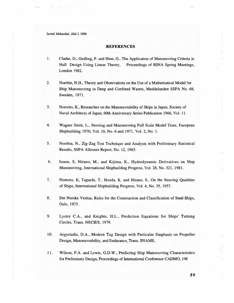
REFERENCES
1. Clarke, D., Gedling, P. and Hine, G., The Application of Manoeuvring Criteria in
Hull Design Using Linear Theory, Proceedings of RINA Spring Meetings,
London 1982.
2. Norrbin, N.H., Theory and Observations on the Use of a Mathematical Model for
Ship Manoeuvring in Deep and Confined Waters, Meddelanden SSPA No. 68,
Sweden, 1971.
3. Nomoto, K., Researches on the Manoeuvrability of Ships in Japan, Society of
Naval Architects of Japan, 60th Anniversary Series Publication 1966, Vol. 11.
4. Wagner Smitt, L., Steering and Manoeuvring Full Scale Model Tests, European
Shipbuilding 1970, Vol. 16, No.6 and 1971, Vol. 2, No. 1.
5. Norrbin, N., Zig-Zag Test Technique and Analysis with Preliminary Statistical
Results, SSPA Allmann Report, No. 12, 1965.
6. Inuoe, S, Hirano, M., and Kijima, K., Hydrodynamic Derivatives on Ship
Manoeuvring, International Shipbuilding Progress, Vol. 28, No. 321, 1981.
7. Nomoto, K, Taguchi, T., Honda, K. and Hirano, S., On the Steering Qualities
of Ships, International Shipbuilding Progress, Vol. 4, No. 35, 1957.
8. Det Norske Veritas, Rules for the Construction and Classification of Steel Ships,
Oslo, 1975.
9. Lyster C.A., and Knights, H.L., Prediction Equations for Ships' Turning
Circles, Trans. NECIES, 1979.
10. Argyriadis, D.A., Modem Tug Design with Particular Emphasis on Propeller
Design, Manoeuvrability, and Endurance, Trans. SNAME,
11. Wilson, P.A. and Lewis, G.D.W., Predicting Ship Manoeuvring Characteristics
for Preliminary Design, Proceedings of International Conference CADMO, 198
59
[urnal Mekilnikill, Jilid I, 1996
12. Inoue, S., Hirano, M., Kijima, K. and Takashima, J., A Practical Calculation
Method of Ship Manoeuvring Motion, International Shipbuilding Progress, Vol.
28, No.325, 1981.
13. Balestrieri, R. and Biancardi, C.G., Computational Hydrodynamics and Ship
Manoeuvring Characteristics, Proceedings of International Conference CADMO,
1988.
14. Dand, I. W., Hydrodynamic Aspects of the Sinking of the Ferry 'Herald of Free
Enterprise', Trans. RINA, 1988.
15. Ogawa, A. and Kasai, H., On the Mathematical Model of Manoeuvring Motion
of Ships, International Shipbuilding Progress, Vol. 25, 1978.
60