Embed Size (px)
Citation preview

Appendix I
Estimated Site Life
NYSDEC OHMS Document No. 201469232-00007

081911807 Appendix I-rev Feb 2013.doc Page 1 of 3
Calculation Sheet
Imagine the result
Client: CWM Chemical Services, LLC Project Location: Model City, New York Project: RMU-2 Design Calculations Project No.: B0023725.2011 Subject: Appendix I: Estimated Site Life Prepared By: BMS Date: February 2013 Reviewed By: BMS Date: February 2013 Checked By: PHB U Date: February 2013 OBJECTIVE: Determine the estimated site life for RMU-2. REFERENCES: 1. RMU-2 Permit Drawing No. 6 entitled "Top of Waste Grades", ARCADIS, February 2013. 2. RMU-2 Permit Drawing No. 5 entitled "Top of Operations Layer Grades", ARCADIS, February 2013. 3. Terramodel v10.52, Trimble Navigation Limited. 4. RMU-2 Engineering Report, ARCADIS February 2013. 5. Engineering Report for Residuals Management Unit 1, Earth Tech. ASSUMPTIONS: 1. Average incoming waste to the facility is a maximum of 500,000 tons/year (as specified by CWM). 2. The volume of select fill placed for access roads and around vertical risers throughout the cell areas
is estimated to be 96,700 in-place cubic yards (cy). This volume was determined based on information presented in Reference 5 and assuming a similar ratio (0.024) of select fill to total airspace.
3. Approximate RMU-2 total airspace from top of operations layer to bottom of final cover is 4,030,700
cy based on References 1, 2 and 3. 4. Bulking of the placed waste material is expected. A portion of the bulking will be a direct result from
the inclusion of stabilizing agents to the fraction of waste requiring use of these items. For the following calculation it has been assumed that approximately 25% of the incoming waste will need stabilization. Stabilized waste is assumed to contain 20%, by volume, stabilizing agents. The total waste bulking percentage is expected to be offset by the total percentage of the compaction of the waste due to construction/operation equipment (Reference 5).
5. Assumed unit weights:
Composite in-place waste material (stabilized and non-stabilized) and select fill = 111.1 lb/ft3
NYSDEC OHMS Document No. 201469232-00007

081911807 Appendix I-rev Feb 2013.doc Page 2 of 3
Calculation Sheet
Imagine the result
(Reference 5)
Average in-place soil = 100 lb/ft3 (Reference 5)
Stabilized waste material = 115 lb/ft3 (Reference 5) CALCULATIONS: 1. Net Volume Available in RMU-2 for Waste Placement (Volumes Rounded to Nearest 100 cy) Total Airspace (Assumption 3) = 4,030,700 cy Volume of Select Fill for Access Roads and Around Vertical Risers (Assumption 2) = 96,700 cy Total Net Volume Available for Waste Material (Including Stabilizing Agents) = 3,934,000 cy Volume Occupied by Stabilizing Agents (3,934,000 cy x 0.25 x 0.20, Assumption 4) = 196,700 cy Net Volume Available for Incoming Waste Materials = 3,737,300 cy 2. Unit Weight of In-Place Waste With the inclusion of stabilizing agents and select fill material into the landfill volume, the actual unit weight of the material in the landfill is greater than the unit weight of the incoming waste material. Assuming the average unit weight of in-place waste and select fill used for access roads, vertical risers, and daily cover is 111.1 lb/ft, the following mass balance may be written:
VSF*SF + VAW*AW = V* where,
VSF = volume of select fill within RMU-2 used for access roads and vertical risers, = 96,700 cy SF = in-place unit weight of select fill = 100 lb/ft VAW = total net volume available within RMU-2 for waste material = 3,934,000 cy AW = average in-place unit weight of waste (unknown) V = total airspace within RMU-2 = 4,030,700 cy = in-place composite unit weight of waste and select fill = 111.1 lb/ft
Thus, AW = [(111.1 lb/ft3)(4,030,700 cy) – (96,700 cy)(100 lb/ft3)]/ 3,934,000 cy
Average In-Place Unit Weight of Waste (Including Stabilizing Agents and Excluding Select Fill) = 111.37 lb/ft3
Since the average in-place unit weight of waste includes both waste material and stabilizing agents, the following expression may be written to determine the in-place unit weight of the waste material alone:
AW = 0.75 W +0.25SW
where,
AW = average in-place unit weight of stabilized and unstabilized waste (from above) = 111.37 lb/ft3
W = unit weight of waste material (unknown)
NYSDEC OHMS Document No. 201469232-00007

081911807 Appendix I-rev Feb 2013.doc Page 3 of 3
Calculation Sheet
Imagine the result
SW = unit weight of stabilized waste material = 115 lb/ft3 Thus,
W =[111.37 lb/ft3 - (0.25)(115 lb/ft3)]/0.75
In-Place Unit Weight of Waste = 110.16 lb/ft3 = 1.487 tons/cy 3. Estimated RMU-2 Site Life The site life of RMU-2 is estimated using the total net volume available within RMU-2 for incoming waste material, the above-calculated in-place unit weight of waste, and a maximum annual inflow of waste to the facility of 500,000 tons (Assumption 1):
L = Vw/Qw where,
L = site life (unknown) Vw = volume available within RMU-2 for incoming waste material = 3,737,300 cy Qw = maximum annual volumetric inflow of waste to RMU-2 = (500,000 tons/yr)/w = 336,247cy/yr
Thus,
L = (3,737,300 cy)/(336,247 cy/yr) Estimated RMU-2 Site Life = 11.1 years (Minimum)
SUMMARY: Based on a total airspace of 4,030,700 cy and a maximum annual waste inflow of 500,000 tons/year, the site life of RMU-2 is estimated to be approximately 11.1 years. With annual waste inflow less than the assumed maximum, a longer site life will result.
NYSDEC OHMS Document No. 201469232-00007

Appendix J
Fac Pond Transfer Line Calculations
NYSDEC OHMS Document No. 201469232-00007

Appendix J-1
Fac Pond Transfer Line Pipe Crush Analysis at Road Crossings
NYSDEC OHMS Document No. 201469232-00007

0221211807 revised November 2013.doc Page 1 of 4
Calculation Sheet
Imagine the result
Client: CWM Chemical Services, LLC Project Location: Model City, New York Project: RMU-2 Design Calculations Project No.: B0023725.2011 Subject: Appendix J-1: Fac Pond Transfer Line Pipe Crush Analysis at Road Crossings Prepared By: BMS Date: November 2013 Reviewed By: PHB Date: November 2013 Checked By: JM U Date: November 2013 OBJECTIVE: Determine the minimum required wall thickness for the proposed ductile iron sleeve pipes to be used to protect the high-density polyethylene (HDPE) fac pond transfer line at road crossings. REFERENCES: 1. Fac Pond 5 Permit Drawings, ARCADIS, February 2013 (revised November 2013).
2. “Truck Loads on Pipe Buried at Shallow Depths,” Ductile Iron Pipe Research Association (DIPRA),
January 2009 (attached).
3. National Engineering Handbook, U.S. Department of Agriculture, Natural Resources Conservation Service, Chapter 52 – Structural Design of Flexible Conduits, pp. 52-8, 52-11, and 52-12 (attached).
4. “Design of Ductile Iron Pipe,” DIPRA, October 2006 (attached). ASSUMPTIONS: 1. The proposed fac pond transfer pipeline consists of two double-contained HDPE pipes in parallel (6-
inch-diameter DR 11 carrier pipe inside of 10-inch-diameter DR 11 containment pipe). Where the HDPE pipes cross site roads, they will be sleeved inside of ductile iron pipes. Thus, this analysis focuses on the ability of the ductile iron pipe to withstand the stresses due to truck traffic and burial at road crossings. All other reaches of the pipeline where sleeve pipes are not identified are assumed to not be subject to and will be protected from vehicle loading by surface grading and/or road edge markers.
2. A nominal 12-inch-diameter ductile iron casing pipe will be used to protect the HDPE pipeline from stresses due to truck traffic at all road crossing locations. This allows the pipe to be installed with less cover. The ductile iron pipe has an actual outer diameter of 13.20 inches (Reference 4) and allows the 10-inch-diameter HDPE containment pipe to be installed inside of the casing pipe with some interstitial space between the inner diameter of the ductile iron pipe and the outer diameter of the HDPE pipe. To reduce the height of the road crossing to the extent possible, a minimum of 9 inches of cover is proposed over the top of the ductile iron pipe.
3. References 2 and 4 are used to model the performance of ductile iron pipe at roadway crossings.
These references are specific to ductile iron pipe and truck loadings at shallow burial depths. The procedure contained in these references checks both bending stress and ring deflection. Per Reference 4, the maximum design ring bending stress is 48,000 psi and the maximum ring deflection for pipes with flexible linings is 5.0 percent.
NYSDEC OHMS Document No. 201469232-00007

0221211807 revised November 2013.doc Page 2 of 4
Calculation Sheet
Imagine the result
4. Vehicle traffic is assumed to consist of a semi-truck with a maximum single axle load of 40,000 pounds (lbs) (based on American Association of State Highway and Transportation Officials HS-25 loading). Thus, each set of dual wheels is assumed to carry a maximum load of 20,000 lbs. The static wheel load of 20,000 lbs is multiplied by an impact factor of 2.0 to account for dynamic effects due to the truck traveling at speed over an uneven road surface. It is noted that Reference 3 suggests a value of 1.3 for pipes with cover thicknesses of 12 inches of less so the 2.0 value is somewhat conservative.
5. The bedding material and remaining backfill are conservatively assumed to have a unit weight of 130
pounds per cubic foot (pcf). CALCULATIONS: The design of the ductile iron pipes used to protect the HDPE pipes at road crossings is evaluated using ductile iron-specific methods as published by DIPRA. Reference 4 is a DIPRA guidance document for determining the minimum wall thickness for ductile iron pipes subject to internal pressure, burial, and truck loading. Reference 2 is a DIPRA guidance document that is used to evaluate the effect of truck loading on ductile iron pipes buried at shallow (less than 2.5 feet) depths. The ductile iron sleeve pipes are designed to withstand the applied loading due to burial and assuming the occurrence of surface loads consisting of loaded semi-trucks conforming to the HS-25 configuration. According to Reference 4, the minimum wall thickness is based on the larger of the two calculated thicknesses for containing internal pressures and for withstanding external loads. In this application, the sleeve pipe is not pressurized so the minimum wall thickness is based on withstanding external loads only. For ductile iron pipes buried at shallow depths and subject to truck loads, Reference 2 is used to calculate the pressure at the top of the pipe due to truck loads at the ground surface as follows:
where, Pt = truck load at top of pipe in pounds per square inch (psi) R = reduction factor due to only part of the pipe being subjected to full intensity of
truck load = 1 (Table 2, Reference 4) F = wheel impact factor = 2.0 (Assumption 4) C = surface load factor (see equation below for value) P = wheel load in pounds = ½ of HS-25 axle load = 20,000 lbs b = effective pipe length = 36 inches (value to assume per Reference 2) D = outside diameter of ductile iron pipe = 13.20 inches (Table 3, Reference 4)
The surface load factor, C, is based on the integration of the Bousinnesq stress distribution formula and accounts for the vertical distance between the ground surface (point of wheel load application) and the top of the pipe as well as the horizontal distance between the point of wheel load application and the top of the pipe. Because the wheel load is assumed to eventually pass over the top of the pipe, the surface load factor is calculated for the instant in time when the wheel is directly over the top of the pipe. depth of the top of pipe Reference 2 gives the following equation for the calculation of the surface load factor:
NYSDEC OHMS Document No. 201469232-00007

0221211807 revised November 2013.doc Page 3 of 4
Calculation Sheet
Imagine the result
where, H = depth of cover over top of pipe (ft) = 0.75 feet (Assumption 2) A = outside radius of pipe (ft) = 0.55 feet
Using the above formula, the surface load factor, C, is found to be 0.6922. Thus the truck load at the top of the pipe, Pt, equals 58.3 psi. The indicated cover depth of 0.75 feet (minimum) produces an earth load, Pe, of approximately 98 pounds per square feet (0.75 feet x 130 pcf) or approximately 0.7 psi. Thus, the total trench load, Pv, equals 59.0 psi. By trial and error, a net wall thickness of 0.36 inches is found to be the minimum for the ductile iron casing pipe using the following equation from Reference 4:
where,
Pv(max) = max trench load based on max design ring bending stress of 48,000 psi f = design max bending stress = 48,000 psi D = outside diameter (in) = 13.20 inches t = net wall thickness (in) = 0.36 inches (found by trial and error) Kb = bending moment coefficient (Table 1, Reference 4, assuming Type 2 laying condition) = 0.210 Kx = deflection coefficient (Table 1, Reference 4, assuming Type 2 laying condition) = 0.105 E = modulus of elasticity for ductile iron = 24,000,000 psi (Reference 4) E’ = modulus of soil reaction (Table 1, Reference 4, assuming Type 2 laying condition) = 300 psi
Using the above formula, Pv(max) is found to equal 60.2 psi, which exceeds the total calculated trench load of 59.0 psi. As recommended in Reference 4, an additional 0.08 inches is added to the net wall thickness to yield a minimum manufacturing thickness of 0.44 inches. This 0.08 inch “service allowance” is intended to provide an additional safety factor for unknowns. Finally, the minimum manufacturing thickness of 0.44 inches is used to verify that the maximum ring deflection is less than the 5 percent maximum value recommended by DIPRA. Reference 4 gives the following formula for verifying that the maximum ring deflection value is not exceeded:
where, Pv(5% Defl) = max trench load corresponding to 5 percent deflection D = outside diameter (in) = 13.20 inches t1 = min manufacturing thickness (in) = 0.44 inches Kx = deflection coefficient (Table 1, Reference 4, assuming Type 2 laying condition) = 0.105 E = modulus of elasticity for ductile iron = 24,000,000 psi (Reference 4)
NYSDEC OHMS Document No. 201469232-00007

0221211807 revised November 2013.doc Page 4 of 4
Calculation Sheet
Imagine the result
E’ = modulus of soil reaction (Table 1, Reference 4, assuming Type 2 laying condition) = 300 psi
Using the above formula, Pv(5% Defl) is found to equal 321 psi, which exceeds the total calculated trench load of 59.0 psi. Thus, the pipe is not predicted to experience deflection greater than the maximum recommended value of 5 percent. SUMMARY: The ductile iron sleeve pipes used to protect the HDPE pipes at road crossings require a net wall thickness of 0.36 inches. With the inclusion of DIPRA-recommended service allowance and casting tolerance of 0.08 and 0.06 inches, respectively, the minimum wall thickness for the ductile iron pipe is 0.50 inches.
NYSDEC OHMS Document No. 201469232-00007

Attachment 1
References
NYSDEC OHMS Document No. 201469232-00007

NYSDEC OHMS Document No. 201469232-00007

NYSDEC OHMS Document No. 201469232-00007

NYSDEC OHMS Document No. 201469232-00007

NYSDEC OHMS Document No. 201469232-00007

NYSDEC OHMS Document No. 201469232-00007

NYSDEC OHMS Document No. 201469232-00007

NYSDEC OHMS Document No. 201469232-00007

NYSDEC OHMS Document No. 201469232-00007

NYSDEC OHMS Document No. 201469232-00007

NYSDEC OHMS Document No. 201469232-00007

NYSDEC OHMS Document No. 201469232-00007

NYSDEC OHMS Document No. 201469232-00007

NYSDEC OHMS Document No. 201469232-00007

NYSDEC OHMS Document No. 201469232-00007
NYSDEC OHMS Document No. 201469232-00007

NYSDEC OHMS Document No. 201469232-00007

NYSDEC OHMS Document No. 201469232-00007

NYSDEC OHMS Document No. 201469232-00007

Appendix J-2
Fac Pond Transfer Line Hydraulic Analysis
NYSDEC OHMS Document No. 201469232-00007

0331211807- J-2 Fac Pond Tansfer Line Calcs - revised November 2013.doc Page 1 of 4
Calculation Sheet
Imagine the result
Client: CWM Chemical Services, LLC Project Location: Model City, New York Project: RMU-2 Design Calculations Project No.: B0023725.2011 Subject: Appendix J-2 : Fac Pond Transfer Line Hydraulic Analysis Prepared By: PTO/NWF/BMS Date: November 2013 Checked By: BMS Date: November 2013
Reviewed By: BMS Date: November 2013 TASK: Model the hydraulics of the proposed high-density polyethylene (HDPE) pipeline between Fac Ponds 1 and 2 and Fac Pond 5. Identify a continuous-duty submersible pump that could potentially be used in the fac ponds and estimate the in-service flowrate that could be achieved when transferring impounded liquid from one pond to the other and when discharging from Fac Pond 5 to the Niagara River outfall. REFERENCES: 1. “Leachate Level Compliance Plan for Residuals Management Unit 1, Cells 1 through 14 – Final
Sequence Phase 3” prepared by ARCADIS, dated August 2011 (Revised November 2011). 2. WaterCAD for Windows, Version 5.0, pressure network analysis software, Haestad Methods, Inc.
3. Fac Pond 5 Permit Drawings, ARCADIS, February 2013 (revised November 2013).
4. Literature from Performance Pipe (attached).
5. Flygt Pumps Literature from Xylem, Inc. (attached). ASSUMPTIONS:
1. The existing Fac Ponds 1 and 2 will be maintained and a new Fac Pond 5 will be constructed to
provide on-site storage and qualification of treated leachate prior to discharge to the Niagara River. A new buried double-contained HDPE transfer pipeline is proposed to allow for the transfer of impounded liquid between the two fac ponds and to allow the discharge of impounded liquid in either fac pond to the Niagara River outfall.
2. Continuous-duty submersible pumps will be installed in each fac pond to dewater the pond (one pump per pond). For maintenance and repair reasons, the same pump model will likely be used in both ponds. The pumps will be mounted on floating platforms so that the pumps can be accessed for repairs regardless of pond liquid levels. Because the pumps will rise and fall with liquid elevations and may move laterally to some extent, 6-inch-diameter flex hose will be used to connect the pumps to the HDPE fac pond transfer pipeline on the fac pond perimeter berms.
3. To discharge impounded water off site to the Niagara River outfall, a connection from the proposed
fac pond transfer line to existing subsurface piping will be made immediately north of Fac Ponds 1 and 2 as shown in Reference 3. By aligning the appropriate valves in the proposed valve house, flow can be diverted from the transfer pipeline, through above-grade filters, and into the existing
NYSDEC OHMS Document No. 201469232-00007
0331211807- J-2 Fac Pond Tansfer Line Calcs - revised November 2013.doc Page 2 of 4
Calculation Sheet
Imagine the result
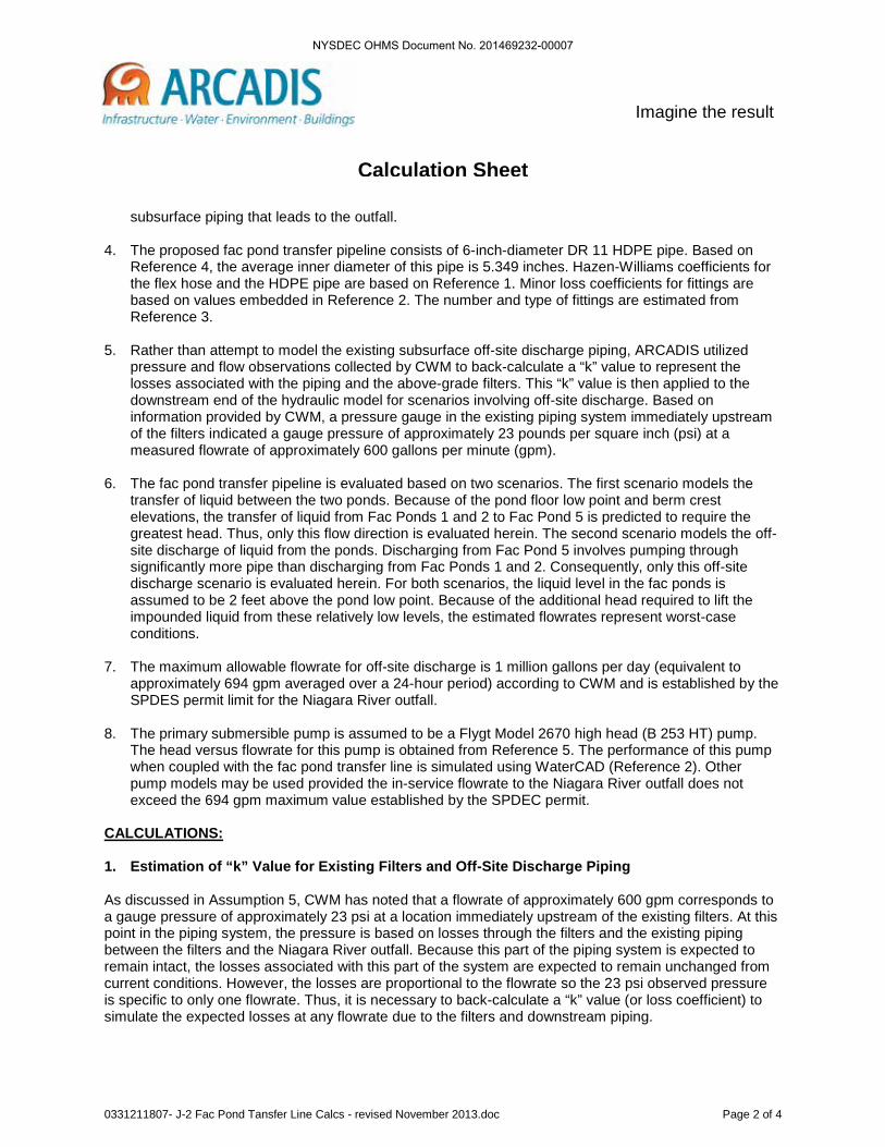
subsurface piping that leads to the outfall.
4. The proposed fac pond transfer pipeline consists of 6-inch-diameter DR 11 HDPE pipe. Based on Reference 4, the average inner diameter of this pipe is 5.349 inches. Hazen-Williams coefficients for the flex hose and the HDPE pipe are based on Reference 1. Minor loss coefficients for fittings are based on values embedded in Reference 2. The number and type of fittings are estimated from Reference 3.
5. Rather than attempt to model the existing subsurface off-site discharge piping, ARCADIS utilized
pressure and flow observations collected by CWM to back-calculate a “k” value to represent the losses associated with the piping and the above-grade filters. This “k” value is then applied to the downstream end of the hydraulic model for scenarios involving off-site discharge. Based on information provided by CWM, a pressure gauge in the existing piping system immediately upstream of the filters indicated a gauge pressure of approximately 23 pounds per square inch (psi) at a measured flowrate of approximately 600 gallons per minute (gpm).
6. The fac pond transfer pipeline is evaluated based on two scenarios. The first scenario models the transfer of liquid between the two ponds. Because of the pond floor low point and berm crest elevations, the transfer of liquid from Fac Ponds 1 and 2 to Fac Pond 5 is predicted to require the greatest head. Thus, only this flow direction is evaluated herein. The second scenario models the off-site discharge of liquid from the ponds. Discharging from Fac Pond 5 involves pumping through significantly more pipe than discharging from Fac Ponds 1 and 2. Consequently, only this off-site discharge scenario is evaluated herein. For both scenarios, the liquid level in the fac ponds is assumed to be 2 feet above the pond low point. Because of the additional head required to lift the impounded liquid from these relatively low levels, the estimated flowrates represent worst-case conditions.
7. The maximum allowable flowrate for off-site discharge is 1 million gallons per day (equivalent to
approximately 694 gpm averaged over a 24-hour period) according to CWM and is established by the SPDES permit limit for the Niagara River outfall.
8. The primary submersible pump is assumed to be a Flygt Model 2670 high head (B 253 HT) pump.
The head versus flowrate for this pump is obtained from Reference 5. The performance of this pump when coupled with the fac pond transfer line is simulated using WaterCAD (Reference 2). Other pump models may be used provided the in-service flowrate to the Niagara River outfall does not exceed the 694 gpm maximum value established by the SPDEC permit.
CALCULATIONS: 1. Estimation of “k” Value for Existing Filters and Off-Site Discharge Piping As discussed in Assumption 5, CWM has noted that a flowrate of approximately 600 gpm corresponds to a gauge pressure of approximately 23 psi at a location immediately upstream of the existing filters. At this point in the piping system, the pressure is based on losses through the filters and the existing piping between the filters and the Niagara River outfall. Because this part of the piping system is expected to remain intact, the losses associated with this part of the system are expected to remain unchanged from current conditions. However, the losses are proportional to the flowrate so the 23 psi observed pressure is specific to only one flowrate. Thus, it is necessary to back-calculate a “k” value (or loss coefficient) to simulate the expected losses at any flowrate due to the filters and downstream piping.
NYSDEC OHMS Document No. 201469232-00007

0331211807- J-2 Fac Pond Tansfer Line Calcs - revised November 2013.doc Page 3 of 4
Calculation Sheet
Imagine the result
Applying the energy equation between the point in the existing piping system corresponding to the pressure gauge location (point 1) and the Niagara River water surface at the pipe outfall (point 2) results in the following expression:
where,
V1 = flow velocity at point 1 = 8.6 ft/s (based on assumed 6-inch-diameter pipe) P1 = gauge pressure in piping system at point 1 = 23 psi (Assumption 5) z1 = elevation of point 1 = 320 ft (approximately) V2 = flow velocity at point 2 = 0 ft/s (flow velocity of jet is negligible at river surface) P2 = gauge pressure at point 2 = 0 psi (atmospheric pressure at river surface) z2 = elevation of point 2 = 245 ft (river surface approximately equal to average Lake Ontario water surface elevation) hL = headloss in system between points 1 and 2 = unknown
Substituting the above values and solving for the headloss results in approximately 129 feet of headloss. Note that this value includes not only friction and minor losses in the discharge piping but also the pressure drop caused by the filters.
With the headloss known for the 600 gpm flowrate, a loss coefficient, k, can be calculated to represent the headloss in the existing discharge piping and filters for any flowrate as follows:
where,
hL = headloss in system between points 1 and 2 at 600 gpm flow = 129 ft (determined above) V = flow velocity as used in hydraulic model (based on 6-inch-diameter HDPE pipe) = 8.6 ft/s k = loss coefficient accounting for energy loss due to pipe friction and minor losses in fittings and filters = unknown
Substituting the above values and solving for the loss coefficient results in a value of 113. Note that because the loss coefficient will be used in the WaterCAD model of the proposed transfer pipeline and because that model includes only the proposed 6-inch-diameter DR 11 HDPE pipe, the loss coefficient must be calculated using a flow velocity that would occur if the discharge piping had an identical pipe diameter (5.349 inches). 2. Fac Pond Transfer Line Hydraulic Model and Estimated Flowrates
WaterCAD is used to model the hydraulics of the proposed fac pond transfer line for both scenarios described in Assumption 6. A summary of the WaterCAD output for flow for each scenario is presented in Table 1 assuming use of a Flygt model 2670 high head pump model (Assumption 8). This pump model was selected to simulate in-service flowrates using a typical submersible pump. Consequently, it is not a requirement to use only this pump model and other manufacturers and models may be substituted provided they meet CWM’s operational requirements and do not exceed the maximum off-site discharge limit of 694 gpm.
NYSDEC OHMS Document No. 201469232-00007

0331211807- J-2 Fac Pond Tansfer Line Calcs - revised November 2013.doc Page 4 of 4
Calculation Sheet
Imagine the result
Table 1 – Estimated Flows for Fac Pond Transfer Pipeline
Scenario Description Potential Pump Model
Predicted Flowrate with Identified
Pump (gpm) Pump Head
(ft)
Fac Ponds 1 and 2 to Fac Pond 5 Flygt 2670 High Head
(B 253 HT)
483 130
Fac Pond 5 to Niagara River Outfall 496 127
Detailed WaterCAD output for both pumping scenarios is provided in Attachment 1. Also included in Attachment 1 are plots of the system and pump curves for each scenario. The point of pump operation for a given scenario is represented by the intersection of the system and pump curves. SUMMARY: The hydraulics of the proposed fac pond transfer pipeline were evaluated assuming the use of a Flygt model 2670 high head pump. Other pump manufacturers and models may also be used at CWM’s discretion.
NYSDEC OHMS Document No. 201469232-00007

Attachment 1
WaterCAD Output
NYSDEC OHMS Document No. 201469232-00007

Scenario: Base
Title: Fac Pond Transfer Linefac pond transfer line - fac ponds 1-2 to 5 rev no...11/05/13 03:36:25 PM
Blasland Bouck & Lee© Haestad Methods, Inc. 37 Brookside Road Waterbury, CT 06708 USA +1-203-755-1666
Project Engineer: Blasland Bouck & LeeWaterCAD v5.0 [5.0037]
Page 1 of 1
P-1
0
P-9
P-6
P-8
P-7
P-1
3
FAC POND 1/2 TO FAC POND 5
FAC POND TRANSFER CALCS
Flygt 2670 (B 253 HT)
Leak Detect MH - SE Corner SLF 12
Cam-lock Fitting
Free Discharge Top of Fac Pond 5 Berm
HP at SLF 12
Fac Pond 1/2
Leak Detect MH - SW Corner SLF 12
NYSDEC OHMS Document No. 201469232-00007

Graph
Title: Fac Pond Transfer Linefac pond transfer line - fac ponds 1-2 to 5 rev no...11/05/13 03:34:06 PM
Blasland Bouck & Lee© Haestad Methods, Inc. 37 Brookside Road Waterbury, CT 06708 USA +1-203-755-1666
Project Engineer: Blasland Bouck & LeeWaterCAD v5.0 [5.0037]
Page 1 of 1
Flygt 2670 (B 253 HT) (Relative Speed Factor = 1.00)System Head Curve
Discharge(gpm)
(ft)
He
ad
0.0
50.0
100.0
150.0
200.0
250.0
300.0
0.0 100.0 200.0 300.0 400.0 500.0 600.0 700.0 800.0 900.0
Pump Head CurveSystem Head Curve
NYSDEC OHMS Document No. 201469232-00007

Project Inventory
Title: Fac Pond Transfer Linefac pond transfer line - fac ponds 1-2 to 5 rev no...11/05/13 03:35:44 PM
Blasland Bouck & Lee© Haestad Methods, Inc. 37 Brookside Road Waterbury, CT 06708 USA +1-203-755-1666
Project Engineer: Blasland Bouck & LeeWaterCAD v5.0 [5.0037]
Page 1 of 1
Title:Project Engineer:Project Date:Comments:
Fac Pond Transfer LineBlasland Bouck & Lee08/23/11
Scenario Summary
Scenario BasePhysical Alternative Base-PhysicalActive Topology Alternative Base-Active TopologyDemand Alternative Base-Average DailyInitial Settings Alternative Base-Initial SettingsOperational Alternative Base-OperationalLogical Control Set Alternat <All Logical Controls>Age Alternative Base-Age AlternativeConstituent Alternative Base-ConstituentTrace Alternative Base-Trace AlternativeFire Flow Alternative Base-Fire FlowCapital Cost Alternative Base-Capital CostEnergy Cost Alternative Base-Energy CostUser Data Alternative Base-User Data
Liquid Characteristics
Liquid Water at 20C(68F) Specific Gravity 1.00Kinematic Viscosity 1.0804e-5 ft²/s
Network Inventory
Pressure Pipes 6 Number of Tanks 0Number of Reservoirs 2 - Constant Area: 0Number of Pressure Junctio 4 - Variable Area: 0Number of Pumps 1 Number of Valves 0- Constant Power: 0 - FCV's: 0- One Point (Design Point): 0 - PBV's: 0- Standard (3 Point): 1 - PRV's: 0- Standard Extended: 0 - PSV's: 0- Custom Extended: 0 - TCV's: 0- Multiple Point: 0 - GPV's: 0Number of Spot Elevations 0
Pressure Pipes Inventory
5.3 in 3,786.00 ft 24.0 in 1.00 ft6.0 in 100.00 ftTotal Length 3,887.00 ft
NYSDEC OHMS Document No. 201469232-00007

Detailed Report for Pressure Junction: Cam-lock Fitting
Title: Fac Pond Transfer Linefac pond transfer line - fac ponds 1-2 to 5 rev no...11/05/13 03:31:02 PM
Blasland Bouck & Lee© Haestad Methods, Inc. 37 Brookside Road Waterbury, CT 06708 USA +1-203-755-1666
Project Engineer: Blasland Bouck & LeeWaterCAD v5.0 [5.0037]
Page 1
Scenario Summary
Scenario BasePhysical Alternative Base-PhysicalActive Topology Alternative Base-Active TopologyDemand Alternative Base-Average DailyInitial Settings Alternative Base-Initial SettingsOperational Alternative Base-OperationalLogical Control Set Alternative <All Logical Controls>Age Alternative Base-Age AlternativeConstituent Alternative Base-ConstituentTrace Alternative Base-Trace AlternativeFire Flow Alternative Base-Fire FlowCapital Cost Alternative Base-Capital CostEnergy Cost Alternative Base-Energy CostUser Data Alternative Base-User Data
Global Adjustments Summary
Demand <None> Roughness <None>
Geometric Summary
X 9,769.97 ft Elevation 322.22 ftY 10,228.59 ft Zone Zone-1
Demand Summary
Type Base Flow(gpm)
Pattern
Demand 0.00 Fixed
User Data
SCADA ID Sampling Point falseHydrant Location false Existing false
Calculated Results Summary
Time(hr)
CalculatedHydraulic Grade
(ft)
Pressure(psi)
PressureHead
(ft)
Demand(Calculated)
(gpm)
0.00 432.41 47.68 110.19 0.00
NYSDEC OHMS Document No. 201469232-00007

Detailed Report for Reservoir: Fac Pond 1/2
Title: Fac Pond Transfer Linefac pond transfer line - fac ponds 1-2 to 5 rev no...11/05/13 03:31:02 PM
Blasland Bouck & Lee© Haestad Methods, Inc. 37 Brookside Road Waterbury, CT 06708 USA +1-203-755-1666
Project Engineer: Blasland Bouck & LeeWaterCAD v5.0 [5.0037]
Page 2
Scenario Summary
Scenario BasePhysical Alternative Base-PhysicalActive Topology Alternative Base-Active TopologyDemand Alternative Base-Average DailyInitial Settings Alternative Base-Initial SettingsOperational Alternative Base-OperationalLogical Control Set Alternative <All Logical Controls>Age Alternative Base-Age AlternativeConstituent Alternative Base-ConstituentTrace Alternative Base-Trace AlternativeFire Flow Alternative Base-Fire FlowCapital Cost Alternative Base-Capital CostEnergy Cost Alternative Base-Energy CostUser Data Alternative Base-User Data
Global Adjustments Summary
Demand <None> Roughness <None>
Geometric Summary
X 9,772.80 ft Elevation 304.18 ftY 10,167.69 ft Zone Zone-1
User Data
Date Installed Date RetiredInspection Date ConditionClearwell Storage false Existing false
Calculated Results Summary
Time(hr)
CalculatedHydraulic Grade
(ft)
Inflow(gpm)
Outflow(gpm)
0.00 304.18 -482.92 482.92
NYSDEC OHMS Document No. 201469232-00007

Detailed Report for Pump: Flygt 2670 (B 253 HT)
Title: Fac Pond Transfer Linefac pond transfer line - fac ponds 1-2 to 5 rev no...11/05/13 03:31:02 PM
Blasland Bouck & Lee© Haestad Methods, Inc. 37 Brookside Road Waterbury, CT 06708 USA +1-203-755-1666
Project Engineer: Blasland Bouck & LeeWaterCAD v5.0 [5.0037]
Page 3
Scenario Summary
Scenario BasePhysical Alternative Base-PhysicalActive Topology Alternative Base-Active TopologyDemand Alternative Base-Average DailyInitial Settings Alternative Base-Initial SettingsOperational Alternative Base-OperationalLogical Control Set Alternative <All Logical Controls>Age Alternative Base-Age AlternativeConstituent Alternative Base-ConstituentTrace Alternative Base-Trace AlternativeFire Flow Alternative Base-Fire FlowCapital Cost Alternative Base-Capital CostEnergy Cost Alternative Base-Energy CostUser Data Alternative Base-User Data
Global Adjustments Summary
Demand <None> Roughness <None>
Geometric Summary
X 9,772.44 ft Upstream Pipe P-6Y 10,192.30 ft Downstream Pipe P-9Elevation 304.18 ft
Pump Definition Summary
Pump Type Standard (3 Point)Shutoff Head 240.00 ft Shutoff Discharge 0.00 gpmDesign Head 140.00 ft Design Discharge 450.00 gpmMaximum Operating Head 30.00 ft Maximum Operating Discharge 800.00 gpm
Initial Status
Initial Pump Status On Initial Relative Speed Factor 1.00
User Data
Date Installed Date RetiredInspection Date SCADA IDRated Power 0 Hp ConditionManufacturer ModelSerial Number Metered falseExisting false
Calculated Results Summary
Time(hr)
ControlStatus
IntakePumpGrade
(ft)
DischargePumpGrade
(ft)
Discharge(gpm)
PumpHead
(ft)
RelativeSpeed
CalculatedWaterPower(Hp)
0.00 On 304.18 434.65 482.92 130.47 1.00 15.91
NYSDEC OHMS Document No. 201469232-00007

Detailed Report for Pump: Flygt 2670 (B 253 HT)
Title: Fac Pond Transfer Linefac pond transfer line - fac ponds 1-2 to 5 rev no...11/05/13 03:31:02 PM
Blasland Bouck & Lee© Haestad Methods, Inc. 37 Brookside Road Waterbury, CT 06708 USA +1-203-755-1666
Project Engineer: Blasland Bouck & LeeWaterCAD v5.0 [5.0037]
Page 4
Flygt 2670 (B 253 HT) (Relative Speed Factor = 1.00)Pump Head Curve
Discharge(gpm)
(ft)
He
ad
0.0
50.0
100.0
150.0
200.0
250.0
0.0 100.0 200.0 300.0 400.0 500.0 600.0 700.0 800.0 900.0
NYSDEC OHMS Document No. 201469232-00007

Detailed Report for Reservoir: Free Discharge Top of Fac Pond 5 Berm
Title: Fac Pond Transfer Linefac pond transfer line - fac ponds 1-2 to 5 rev no...11/05/13 03:31:03 PM
Blasland Bouck & Lee© Haestad Methods, Inc. 37 Brookside Road Waterbury, CT 06708 USA +1-203-755-1666
Project Engineer: Blasland Bouck & LeeWaterCAD v5.0 [5.0037]
Page 5
Scenario Summary
Scenario BasePhysical Alternative Base-PhysicalActive Topology Alternative Base-Active TopologyDemand Alternative Base-Average DailyInitial Settings Alternative Base-Initial SettingsOperational Alternative Base-OperationalLogical Control Set Alternative <All Logical Controls>Age Alternative Base-Age AlternativeConstituent Alternative Base-ConstituentTrace Alternative Base-Trace AlternativeFire Flow Alternative Base-Fire FlowCapital Cost Alternative Base-Capital CostEnergy Cost Alternative Base-Energy CostUser Data Alternative Base-User Data
Global Adjustments Summary
Demand <None> Roughness <None>
Geometric Summary
X 9,767.20 ft Elevation 335.00 ftY 10,398.87 ft Zone Zone-1
User Data
Date Installed Date RetiredInspection Date ConditionClearwell Storage false Existing false
Calculated Results Summary
Time(hr)
CalculatedHydraulic Grade
(ft)
Inflow(gpm)
Outflow(gpm)
0.00 335.00 482.92 -482.92
NYSDEC OHMS Document No. 201469232-00007

Detailed Report for Pressure Junction: HP at SLF 12
Title: Fac Pond Transfer Linefac pond transfer line - fac ponds 1-2 to 5 rev no...11/05/13 03:31:03 PM
Blasland Bouck & Lee© Haestad Methods, Inc. 37 Brookside Road Waterbury, CT 06708 USA +1-203-755-1666
Project Engineer: Blasland Bouck & LeeWaterCAD v5.0 [5.0037]
Page 6
Scenario Summary
Scenario BasePhysical Alternative Base-PhysicalActive Topology Alternative Base-Active TopologyDemand Alternative Base-Average DailyInitial Settings Alternative Base-Initial SettingsOperational Alternative Base-OperationalLogical Control Set Alternative <All Logical Controls>Age Alternative Base-Age AlternativeConstituent Alternative Base-ConstituentTrace Alternative Base-Trace AlternativeFire Flow Alternative Base-Fire FlowCapital Cost Alternative Base-Capital CostEnergy Cost Alternative Base-Energy CostUser Data Alternative Base-User Data
Global Adjustments Summary
Demand <None> Roughness <None>
Geometric Summary
X 9,768.24 ft Elevation 321.80 ftY 10,310.17 ft Zone Zone-1
Demand Summary
Type Base Flow(gpm)
Pattern
Demand 0.00 Fixed
User Data
SCADA ID Sampling Point falseHydrant Location false Existing false
Calculated Results Summary
Time(hr)
CalculatedHydraulic Grade
(ft)
Pressure(psi)
PressureHead
(ft)
Demand(Calculated)
(gpm)
0.00 373.04 22.17 51.24 0.00
NYSDEC OHMS Document No. 201469232-00007

Detailed Report for Pressure Junction: Leak Detect MH - SE Corner SLF 12
Title: Fac Pond Transfer Linefac pond transfer line - fac ponds 1-2 to 5 rev no...11/05/13 03:31:03 PM
Blasland Bouck & Lee© Haestad Methods, Inc. 37 Brookside Road Waterbury, CT 06708 USA +1-203-755-1666
Project Engineer: Blasland Bouck & LeeWaterCAD v5.0 [5.0037]
Page 7
Scenario Summary
Scenario BasePhysical Alternative Base-PhysicalActive Topology Alternative Base-Active TopologyDemand Alternative Base-Average DailyInitial Settings Alternative Base-Initial SettingsOperational Alternative Base-OperationalLogical Control Set Alternative <All Logical Controls>Age Alternative Base-Age AlternativeConstituent Alternative Base-ConstituentTrace Alternative Base-Trace AlternativeFire Flow Alternative Base-Fire FlowCapital Cost Alternative Base-Capital CostEnergy Cost Alternative Base-Energy CostUser Data Alternative Base-User Data
Global Adjustments Summary
Demand <None> Roughness <None>
Geometric Summary
X 9,767.80 ft Elevation 313.40 ftY 10,351.83 ft Zone Zone-1
Demand Summary
Type Base Flow(gpm)
Pattern
Demand 0.00 Fixed
User Data
SCADA ID Sampling Point falseHydrant Location false Existing false
Calculated Results Summary
Time(hr)
CalculatedHydraulic Grade
(ft)
Pressure(psi)
PressureHead
(ft)
Demand(Calculated)
(gpm)
0.00 357.73 19.18 44.33 0.00
NYSDEC OHMS Document No. 201469232-00007

Detailed Report for Pressure Junction: Leak Detect MH - SW Corner SLF 12
Title: Fac Pond Transfer Linefac pond transfer line - fac ponds 1-2 to 5 rev no...11/05/13 03:31:03 PM
Blasland Bouck & Lee© Haestad Methods, Inc. 37 Brookside Road Waterbury, CT 06708 USA +1-203-755-1666
Project Engineer: Blasland Bouck & LeeWaterCAD v5.0 [5.0037]
Page 8
Scenario Summary
Scenario BasePhysical Alternative Base-PhysicalActive Topology Alternative Base-Active TopologyDemand Alternative Base-Average DailyInitial Settings Alternative Base-Initial SettingsOperational Alternative Base-OperationalLogical Control Set Alternative <All Logical Controls>Age Alternative Base-Age AlternativeConstituent Alternative Base-ConstituentTrace Alternative Base-Trace AlternativeFire Flow Alternative Base-Fire FlowCapital Cost Alternative Base-Capital CostEnergy Cost Alternative Base-Energy CostUser Data Alternative Base-User Data
Global Adjustments Summary
Demand <None> Roughness <None>
Geometric Summary
X 9,769.09 ft Elevation 310.20 ftY 10,274.02 ft Zone Zone-1
Demand Summary
Type Base Flow(gpm)
Pattern
Demand 0.00 Fixed
User Data
SCADA ID Sampling Point falseHydrant Location false Existing false
Calculated Results Summary
Time(hr)
CalculatedHydraulic Grade
(ft)
Pressure(psi)
PressureHead
(ft)
Demand(Calculated)
(gpm)
0.00 397.95 37.97 87.75 0.00
NYSDEC OHMS Document No. 201469232-00007

Detailed Report for Pressure Pipe: P-6
Title: Fac Pond Transfer Linefac pond transfer line - fac ponds 1-2 to 5 rev no...11/05/13 03:31:03 PM
Blasland Bouck & Lee© Haestad Methods, Inc. 37 Brookside Road Waterbury, CT 06708 USA +1-203-755-1666
Project Engineer: Blasland Bouck & LeeWaterCAD v5.0 [5.0037]
Page 9
Scenario Summary
Scenario BasePhysical Alternative Base-PhysicalActive Topology Alternative Base-Active TopologyDemand Alternative Base-Average DailyInitial Settings Alternative Base-Initial SettingsOperational Alternative Base-OperationalLogical Control Set Alternative <All Logical Controls>Age Alternative Base-Age AlternativeConstituent Alternative Base-ConstituentTrace Alternative Base-Trace AlternativeFire Flow Alternative Base-Fire FlowCapital Cost Alternative Base-Capital CostEnergy Cost Alternative Base-Energy CostUser Data Alternative Base-User Data
Global Adjustments Summary
Demand <None> Roughness <None>
Pipe Characteristics
Material HDPE Hazen- Williams C 155.0Diameter 24.0 in Minor Loss Coefficient 0.00Check Valve? false Length 1.00 ftFrom Node Fac Pond 1/2 To Node Flygt 2670 (B 253 HT)
Elevations
From Elevation 304.18 ft To Elevation 304.18 ft
Initial Status
Initial Status Open
User Data
Date Installed Date RetiredInspection Date LiningPipe Class Exterior CoatingNominal Diameter 0.00 in ConditionSkeletonized false Metered falseExisting false
Calculated Results Summary
Time(hr)
ControlStatus
Discharge(gpm)
Velocity(ft/s)
Upstream StructureHydraulic Grade
(ft)
Downstream StructureHydraulic Grade
(ft)
CalculatedFriction
Headloss(ft)
CalculatedMinor
Headloss(ft)
PressurePipe
Headloss(ft)
HeadlossGradient(ft/1000ft)
0.00 Open 482.92 0.34 304.18 304.18 0.00 0.00 0.00 0.03
NYSDEC OHMS Document No. 201469232-00007

Detailed Report for Pressure Pipe: P-7
Title: Fac Pond Transfer Linefac pond transfer line - fac ponds 1-2 to 5 rev no...11/05/13 03:31:03 PM
Blasland Bouck & Lee© Haestad Methods, Inc. 37 Brookside Road Waterbury, CT 06708 USA +1-203-755-1666
Project Engineer: Blasland Bouck & LeeWaterCAD v5.0 [5.0037]
Page 10
Scenario Summary
Scenario BasePhysical Alternative Base-PhysicalActive Topology Alternative Base-Active TopologyDemand Alternative Base-Average DailyInitial Settings Alternative Base-Initial SettingsOperational Alternative Base-OperationalLogical Control Set Alternative <All Logical Controls>Age Alternative Base-Age AlternativeConstituent Alternative Base-ConstituentTrace Alternative Base-Trace AlternativeFire Flow Alternative Base-Fire FlowCapital Cost Alternative Base-Capital CostEnergy Cost Alternative Base-Energy CostUser Data Alternative Base-User Data
Global Adjustments Summary
Demand <None> Roughness <None>
Pipe Characteristics
Material HDPE Hazen- Williams C 155.0Diameter 5.3 in Minor Loss Coefficient 0.65Check Valve? false Length 1,004.00 ftFrom Node Leak Detect MH - SW Corner SLF 12 To Node HP at SLF 12
Elevations
From Elevation 310.20 ft To Elevation 321.80 ft
Initial Status
Initial Status Open
User Data
Date Installed Date RetiredInspection Date LiningPipe Class Exterior CoatingNominal Diameter 0.00 in ConditionSkeletonized false Metered falseExisting false
Calculated Results Summary
Time(hr)
ControlStatus
Discharge(gpm)
Velocity(ft/s)
Upstream StructureHydraulic Grade
(ft)
Downstream StructureHydraulic Grade
(ft)
CalculatedFriction
Headloss(ft)
CalculatedMinor
Headloss(ft)
PressurePipe
Headloss(ft)
HeadlossGradient(ft/1000ft)
0.00 Open 482.92 6.89 397.95 373.04 24.43 0.48 24.91 24.81
NYSDEC OHMS Document No. 201469232-00007

Detailed Report for Pressure Pipe: P-8
Title: Fac Pond Transfer Linefac pond transfer line - fac ponds 1-2 to 5 rev no...11/05/13 03:31:03 PM
Blasland Bouck & Lee© Haestad Methods, Inc. 37 Brookside Road Waterbury, CT 06708 USA +1-203-755-1666
Project Engineer: Blasland Bouck & LeeWaterCAD v5.0 [5.0037]
Page 11
Scenario Summary
Scenario BasePhysical Alternative Base-PhysicalActive Topology Alternative Base-Active TopologyDemand Alternative Base-Average DailyInitial Settings Alternative Base-Initial SettingsOperational Alternative Base-OperationalLogical Control Set Alternative <All Logical Controls>Age Alternative Base-Age AlternativeConstituent Alternative Base-ConstituentTrace Alternative Base-Trace AlternativeFire Flow Alternative Base-Fire FlowCapital Cost Alternative Base-Capital CostEnergy Cost Alternative Base-Energy CostUser Data Alternative Base-User Data
Global Adjustments Summary
Demand <None> Roughness <None>
Pipe Characteristics
Material HDPE Hazen- Williams C 155.0Diameter 5.3 in Minor Loss Coefficient 3.07Check Valve? false Length 1,323.00 ftFrom Node Leak Detect MH - SW Corner SLF 12 To Node Cam-lock Fitting
Elevations
From Elevation 310.20 ft To Elevation 322.22 ft
Initial Status
Initial Status Open
User Data
Date Installed Date RetiredInspection Date LiningPipe Class Exterior CoatingNominal Diameter 0.00 in ConditionSkeletonized false Metered falseExisting false
Calculated Results Summary
Time(hr)
ControlStatus
Discharge(gpm)
Velocity(ft/s)
Upstream StructureHydraulic Grade
(ft)
Downstream StructureHydraulic Grade
(ft)
CalculatedFriction
Headloss(ft)
CalculatedMinor
Headloss(ft)
PressurePipe
Headloss(ft)
HeadlossGradient(ft/1000ft)
0.00 Open -482.92 6.89 397.95 432.41 32.19 2.27 34.46 26.05
NYSDEC OHMS Document No. 201469232-00007

Detailed Report for Pressure Pipe: P-9
Title: Fac Pond Transfer Linefac pond transfer line - fac ponds 1-2 to 5 rev no...11/05/13 03:31:03 PM
Blasland Bouck & Lee© Haestad Methods, Inc. 37 Brookside Road Waterbury, CT 06708 USA +1-203-755-1666
Project Engineer: Blasland Bouck & LeeWaterCAD v5.0 [5.0037]
Page 12
Scenario Summary
Scenario BasePhysical Alternative Base-PhysicalActive Topology Alternative Base-Active TopologyDemand Alternative Base-Average DailyInitial Settings Alternative Base-Initial SettingsOperational Alternative Base-OperationalLogical Control Set Alternative <All Logical Controls>Age Alternative Base-Age AlternativeConstituent Alternative Base-ConstituentTrace Alternative Base-Trace AlternativeFire Flow Alternative Base-Fire FlowCapital Cost Alternative Base-Capital CostEnergy Cost Alternative Base-Energy CostUser Data Alternative Base-User Data
Global Adjustments Summary
Demand <None> Roughness <None>
Pipe Characteristics
Material flex hose Hazen- Williams C 120.0Diameter 6.0 in Minor Loss Coefficient 0.00Check Valve? false Length 100.00 ftFrom Node Flygt 2670 (B 253 HT) To Node Cam-lock Fitting
Elevations
From Elevation 304.18 ft To Elevation 322.22 ft
Initial Status
Initial Status Open
User Data
Date Installed Date RetiredInspection Date LiningPipe Class Exterior CoatingNominal Diameter 0.00 in ConditionSkeletonized false Metered falseExisting false
Calculated Results Summary
Time(hr)
ControlStatus
Discharge(gpm)
Velocity(ft/s)
Upstream StructureHydraulic Grade
(ft)
Downstream StructureHydraulic Grade
(ft)
CalculatedFriction
Headloss(ft)
CalculatedMinor
Headloss(ft)
PressurePipe
Headloss(ft)
HeadlossGradient(ft/1000ft)
0.00 Open 482.92 5.48 434.65 432.41 2.23 0.00 2.23 22.34
NYSDEC OHMS Document No. 201469232-00007

Detailed Report for Pressure Pipe: P-10
Title: Fac Pond Transfer Linefac pond transfer line - fac ponds 1-2 to 5 rev no...11/05/13 03:31:03 PM
Blasland Bouck & Lee© Haestad Methods, Inc. 37 Brookside Road Waterbury, CT 06708 USA +1-203-755-1666
Project Engineer: Blasland Bouck & LeeWaterCAD v5.0 [5.0037]
Page 13
Scenario Summary
Scenario BasePhysical Alternative Base-PhysicalActive Topology Alternative Base-Active TopologyDemand Alternative Base-Average DailyInitial Settings Alternative Base-Initial SettingsOperational Alternative Base-OperationalLogical Control Set Alternative <All Logical Controls>Age Alternative Base-Age AlternativeConstituent Alternative Base-ConstituentTrace Alternative Base-Trace AlternativeFire Flow Alternative Base-Fire FlowCapital Cost Alternative Base-Capital CostEnergy Cost Alternative Base-Energy CostUser Data Alternative Base-User Data
Global Adjustments Summary
Demand <None> Roughness <None>
Pipe Characteristics
Material HDPE Hazen- Williams C 155.0Diameter 5.3 in Minor Loss Coefficient 3.43Check Valve? false Length 830.00 ftFrom Node Leak Detect MH - SE Corner SLF 12 To NodeFree Discharge Top of Fac Pond 5 Berm
Elevations
From Elevation 313.40 ft To Elevation 335.00 ft
Initial Status
Initial Status Open
User Data
Date Installed Date RetiredInspection Date LiningPipe Class Exterior CoatingNominal Diameter 0.00 in ConditionSkeletonized false Metered falseExisting false
Calculated Results Summary
Time(hr)
ControlStatus
Discharge(gpm)
Velocity(ft/s)
Upstream StructureHydraulic Grade
(ft)
Downstream StructureHydraulic Grade
(ft)
CalculatedFriction
Headloss(ft)
CalculatedMinor
Headloss(ft)
PressurePipe
Headloss(ft)
HeadlossGradient(ft/1000ft)
0.00 Open 482.92 6.89 357.73 335.00 20.20 2.53 22.73 27.39
NYSDEC OHMS Document No. 201469232-00007

Detailed Report for Pressure Pipe: P-13
Title: Fac Pond Transfer Linefac pond transfer line - fac ponds 1-2 to 5 rev no...11/05/13 03:31:03 PM
Blasland Bouck & Lee© Haestad Methods, Inc. 37 Brookside Road Waterbury, CT 06708 USA +1-203-755-1666
Project Engineer: Blasland Bouck & LeeWaterCAD v5.0 [5.0037]
Page 14
Scenario Summary
Scenario BasePhysical Alternative Base-PhysicalActive Topology Alternative Base-Active TopologyDemand Alternative Base-Average DailyInitial Settings Alternative Base-Initial SettingsOperational Alternative Base-OperationalLogical Control Set Alternative <All Logical Controls>Age Alternative Base-Age AlternativeConstituent Alternative Base-ConstituentTrace Alternative Base-Trace AlternativeFire Flow Alternative Base-Fire FlowCapital Cost Alternative Base-Capital CostEnergy Cost Alternative Base-Energy CostUser Data Alternative Base-User Data
Global Adjustments Summary
Demand <None> Roughness <None>
Pipe Characteristics
Material HDPE Hazen- Williams C 155.0Diameter 5.3 in Minor Loss Coefficient 0.00Check Valve? false Length 629.00 ftFrom Node HP at SLF 12 To Node Leak Detect MH - SE Corner SLF 12
Elevations
From Elevation 321.80 ft To Elevation 313.40 ft
Initial Status
Initial Status Open
User Data
Date Installed Date RetiredInspection Date LiningPipe Class Exterior CoatingNominal Diameter 0.00 in ConditionSkeletonized false Metered falseExisting false
Calculated Results Summary
Time(hr)
ControlStatus
Discharge(gpm)
Velocity(ft/s)
Upstream StructureHydraulic Grade
(ft)
Downstream StructureHydraulic Grade
(ft)
CalculatedFriction
Headloss(ft)
CalculatedMinor
Headloss(ft)
PressurePipe
Headloss(ft)
HeadlossGradient(ft/1000ft)
0.00 Open 482.92 6.89 373.04 357.73 15.31 0.00 15.31 24.34
NYSDEC OHMS Document No. 201469232-00007

Scenario: Base
Title: Fac Pond Transfer Linefac pond transfer line - fac pond 5 to river.wcd01/24/12 04:53:42 PM
Blasland Bouck & Lee© Haestad Methods, Inc. 37 Brookside Road Waterbury, CT 06708 USA +1-203-755-1666
Project Engineer: Blasland Bouck & LeeWaterCAD v5.0 [5.0037]
Page 1 of 1
P-8
P-7
P-1
3
Exi
stin
g Fi
lters
/Off-
Site
Dis
char
ge P
ipin
g
P-1
7P
-16
P-1
0
OFF-SITE DISCHARGEFAC POND TRANSFER CALCS
RiserNia gara River
Flygt 2670 (B 253 HT)
Connection to F ilters
HP a t SLF 1 2
Leak De te ct MH - SE C orn er SL F 12
Leak De te ct MH - SW Corne r SLF 12
Fac Pond 5
NYSDEC OHMS Document No. 201469232-00007

Graph
Title: Fac Pond Transfer Linefac pond transfer line - fac pond 5 to river.wcd01/25/12 01:52:08 PM
Blasland Bouck & Lee© Haestad Methods, Inc. 37 Brookside Road Waterbury, CT 06708 USA +1-203-755-1666
Project Engineer: Blasland Bouck & LeeWaterCAD v5.0 [5.0037]
Page 1 of 1
Flygt 2670 (B 253 HT) (Relative Speed Factor = 1.00)System Head Curve
Discharge(gpm)
(ft)
He
ad
-100.0
-50.0
0.0
50.0
100.0
150.0
200.0
250.0
300.0
350.0
400.0
450.0
0.0 100.0 200.0 300.0 400.0 500.0 600.0 700.0 800.0 900.0
Pump Head CurveSystem Head Curve
NYSDEC OHMS Document No. 201469232-00007

Analysis ResultsScenario: Base
Steady State Analysis
Title: Fac Pond Transfer Linefac pond transfer line - fac pond 5 to river.wcd01/25/12 01:52:34 PM
Blasland Bouck & Lee© Haestad Methods, Inc. 37 Brookside Road Waterbury, CT 06708 USA +1-203-755-1666
Project Engineer: Blasland Bouck & LeeWaterCAD v5.0 [5.0037]
Page 1
Title:Project Engineer:Project Date:Comments:
Fac Pond Transfer LineBlasland Bouck & Lee08/23/11
Scenario Summary
Scenario BasePhysical Alternative Base-PhysicalActive Topology Alternative Base-Active TopologyDemand Alternative Base-Average DailyInitial Settings Alternative Base-Initial SettingsOperational Alternative Base-OperationalLogical Control Set Alternative <All Logical Controls>Age Alternative Base-Age AlternativeConstituent Alternative Base-ConstituentTrace Alternative Base-Trace AlternativeFire Flow Alternative Base-Fire FlowCapital Cost Alternative Base-Capital CostEnergy Cost Alternative Base-Energy CostUser Data Alternative Base-User Data
Liquid Characteristics
Liquid Water at 20C(68F) Specific Gravity 1.00Kinematic Viscosity 1.0804e-5 ft²/s
Network Inventory
Pressure Pipes 7 Number of Tanks 0Number of Reservoirs 2 - Constant Area: 0Number of Pressure Junctions 5 - Variable Area: 0Number of Pumps 1 Number of Valves 0- Constant Power: 0 - FCV's: 0- One Point (Design Point): 0 - PBV's: 0- Standard (3 Point): 1 - PRV's: 0- Standard Extended: 0 - PSV's: 0- Custom Extended: 0 - TCV's: 0- Multiple Point: 0 - GPV's: 0Number of Spot Elevations 0
Pressure Pipes Inventory
5.3 in 3,637.00 ft 6.0 in 150.00 ftTotal Length 3,787.00 ft
NYSDEC OHMS Document No. 201469232-00007

Analysis ResultsScenario: Base
Steady State Analysis
Title: Fac Pond Transfer Linefac pond transfer line - fac pond 5 to river.wcd01/25/12 01:52:35 PM
Blasland Bouck & Lee© Haestad Methods, Inc. 37 Brookside Road Waterbury, CT 06708 USA +1-203-755-1666
Project Engineer: Blasland Bouck & LeeWaterCAD v5.0 [5.0037]
Page 2
Pressure Junctions @ 0.00 hr
Label CalculatedHydraulic Grade
(ft)
Pressure(psi)
PressureHead
(ft)
Demand(Calculated)
(gpm)
Connection to Filters 333.11 5.67 13.11 0.00HP at SLF 12 393.66 31.09 71.86 0.00Leak Detect MH - SE Corner SLF 12409.76 41.69 96.36 0.00Leak Detect MH - SW Corner SLF 12367.45 24.77 57.25 0.00Riser 432.02 41.98 97.02 0.00
Pressure Pipes @ 0.00 hr
Label ControlStatus
Discharge(gpm)
Velocity(ft/s)
Upstream StructureHydraulic Grade
(ft)
Downstream StructureHydraulic Grade
(ft)
CalculatedFriction
Headloss(ft)
CalculatedMinor
Headloss(ft)
PressurePipe
Headloss(ft)
HeadlossGradient(ft/1000ft)
Existing Filters/Off-Site Discharge PipingOpen 496.28 7.09 333.11 245.00 -0.06 88.16 88.11 88,105.20P-7 Open 496.28 7.09 393.66 367.45 25.70 0.51 26.21 26.10P-8 Open 496.28 7.09 367.45 333.11 30.53 3.82 34.35 28.79P-10 Open 496.28 7.09 432.02 409.76 20.73 1.53 22.26 27.48P-13 Open 496.28 7.09 409.76 393.66 16.10 0.00 16.10 25.60P-16 Open 496.28 5.63 309.00 308.76 0.24 0.00 0.24 23.50P-17 Open 496.28 5.63 435.31 432.02 3.29 0.00 3.29 23.50
Reservoirs @ 0.00 hr
Label CalculatedHydraulic Grade
(ft)
Inflow(gpm)
Outflow(gpm)
Fac Pond 5 309.00 -496.28 496.28Niagara River 245.00 496.28 -496.28
Pumps @ 0.00 hr
Label ControlStatus
IntakePumpGrade
(ft)
DischargePumpGrade
(ft)
Discharge(gpm)
PumpHead
(ft)
RelativeSpeed
CalculatedWaterPower(Hp)
Flygt 2670 (B 253 HT)On 308.76 435.31 496.28 126.55 1.00 15.86
NYSDEC OHMS Document No. 201469232-00007

Detailed Report for Pressure Junction: Connection to Filters
Title: Fac Pond Transfer Linefac pond transfer line - fac pond 5 to river.wcd01/25/12 01:52:25 PM
Blasland Bouck & Lee© Haestad Methods, Inc. 37 Brookside Road Waterbury, CT 06708 USA +1-203-755-1666
Project Engineer: Blasland Bouck & LeeWaterCAD v5.0 [5.0037]
Page 1
Scenario Summary
Scenario BasePhysical Alternative Base-PhysicalActive Topology Alternative Base-Active TopologyDemand Alternative Base-Average DailyInitial Settings Alternative Base-Initial SettingsOperational Alternative Base-OperationalLogical Control Set Alternative <All Logical Controls>Age Alternative Base-Age AlternativeConstituent Alternative Base-ConstituentTrace Alternative Base-Trace AlternativeFire Flow Alternative Base-Fire FlowCapital Cost Alternative Base-Capital CostEnergy Cost Alternative Base-Energy CostUser Data Alternative Base-User Data
Global Adjustments Summary
Demand <None> Roughness <None>
Geometric Summary
X 10,004.83 ft Elevation 320.00 ftY 10,173.78 ft Zone Zone-1
Demand Summary
Type Base Flow(gpm)
Pattern
Demand 0.00 Fixed
User Data
SCADA ID Sampling Point falseHydrant Location false Existing false
Calculated Results Summary
Time(hr)
CalculatedHydraulic Grade
(ft)
Pressure(psi)
PressureHead
(ft)
Demand(Calculated)
(gpm)
0.00 333.11 5.67 13.11 0.00
NYSDEC OHMS Document No. 201469232-00007

Detailed Report for Pressure Pipe: Existing Filters/Off-Site Discharge Piping
Title: Fac Pond Transfer Linefac pond transfer line - fac pond 5 to river.wcd01/25/12 01:52:25 PM
Blasland Bouck & Lee© Haestad Methods, Inc. 37 Brookside Road Waterbury, CT 06708 USA +1-203-755-1666
Project Engineer: Blasland Bouck & LeeWaterCAD v5.0 [5.0037]
Page 2
Scenario Summary
Scenario BasePhysical Alternative Base-PhysicalActive Topology Alternative Base-Active TopologyDemand Alternative Base-Average DailyInitial Settings Alternative Base-Initial SettingsOperational Alternative Base-OperationalLogical Control Set Alternative <All Logical Controls>Age Alternative Base-Age AlternativeConstituent Alternative Base-ConstituentTrace Alternative Base-Trace AlternativeFire Flow Alternative Base-Fire FlowCapital Cost Alternative Base-Capital CostEnergy Cost Alternative Base-Energy CostUser Data Alternative Base-User Data
Global Adjustments Summary
Demand <None> Roughness <None>
Pipe Characteristics
Material HDPE Hazen- Williams C 155.0Diameter 5.3 in Minor Loss Coefficient 113.00Check Valve? false Length 1.00 ftFrom Node Connection to Filters To Node Niagara River
Elevations
From Elevation 320.00 ft To Elevation 245.00 ft
Initial Status
Initial Status Open
User Data
Date Installed Date RetiredInspection Date LiningPipe Class Exterior CoatingNominal Diameter 0.00 in ConditionSkeletonized false Metered falseExisting false
Calculated Results Summary
Time(hr)
ControlStatus
Discharge(gpm)
Velocity(ft/s)
Upstream StructureHydraulic Grade
(ft)
Downstream StructureHydraulic Grade
(ft)
CalculatedFriction
Headloss(ft)
CalculatedMinor
Headloss(ft)
PressurePipe
Headloss(ft)
HeadlossGradient(ft/1000ft)
0.00 Open 496.28 7.09 333.11 245.00 -0.06 88.16 88.11 88,105.20
NYSDEC OHMS Document No. 201469232-00007

Detailed Report for Reservoir: Fac Pond 5
Title: Fac Pond Transfer Linefac pond transfer line - fac pond 5 to river.wcd01/25/12 01:52:25 PM
Blasland Bouck & Lee© Haestad Methods, Inc. 37 Brookside Road Waterbury, CT 06708 USA +1-203-755-1666
Project Engineer: Blasland Bouck & LeeWaterCAD v5.0 [5.0037]
Page 3
Scenario Summary
Scenario BasePhysical Alternative Base-PhysicalActive Topology Alternative Base-Active TopologyDemand Alternative Base-Average DailyInitial Settings Alternative Base-Initial SettingsOperational Alternative Base-OperationalLogical Control Set Alternative <All Logical Controls>Age Alternative Base-Age AlternativeConstituent Alternative Base-ConstituentTrace Alternative Base-Trace AlternativeFire Flow Alternative Base-Fire FlowCapital Cost Alternative Base-Capital CostEnergy Cost Alternative Base-Energy CostUser Data Alternative Base-User Data
Global Adjustments Summary
Demand <None> Roughness <None>
Geometric Summary
X 9,780.48 ft Elevation 309.00 ftY 10,411.02 ft Zone Zone-1
User Data
Date Installed Date RetiredInspection Date ConditionClearwell Storage false Existing false
Calculated Results Summary
Time(hr)
CalculatedHydraulic Grade
(ft)
Inflow(gpm)
Outflow(gpm)
0.00 309.00 -496.28 496.28
NYSDEC OHMS Document No. 201469232-00007

Detailed Report for Pump: Flygt 2670 (B 253 HT)
Title: Fac Pond Transfer Linefac pond transfer line - fac pond 5 to river.wcd01/25/12 01:52:25 PM
Blasland Bouck & Lee© Haestad Methods, Inc. 37 Brookside Road Waterbury, CT 06708 USA +1-203-755-1666
Project Engineer: Blasland Bouck & LeeWaterCAD v5.0 [5.0037]
Page 4
Scenario Summary
Scenario BasePhysical Alternative Base-PhysicalActive Topology Alternative Base-Active TopologyDemand Alternative Base-Average DailyInitial Settings Alternative Base-Initial SettingsOperational Alternative Base-OperationalLogical Control Set Alternative <All Logical Controls>Age Alternative Base-Age AlternativeConstituent Alternative Base-ConstituentTrace Alternative Base-Trace AlternativeFire Flow Alternative Base-Fire FlowCapital Cost Alternative Base-Capital CostEnergy Cost Alternative Base-Energy CostUser Data Alternative Base-User Data
Global Adjustments Summary
Demand <None> Roughness <None>
Geometric Summary
X 9,781.04 ft Upstream Pipe P-16Y 10,384.75 ft Downstream Pipe P-17Elevation 309.00 ft
Pump Definition Summary
Pump Type Standard (3 Point)Shutoff Head 240.00 ft Shutoff Discharge 0.00 gpmDesign Head 140.00 ft Design Discharge 450.00 gpmMaximum Operating Head 30.00 ft Maximum Operating Discharge 800.00 gpm
Initial Status
Initial Pump Status On Initial Relative Speed Factor 1.00
User Data
Date Installed Date RetiredInspection Date SCADA IDRated Power 0 Hp ConditionManufacturer ModelSerial Number Metered falseExisting false
Calculated Results Summary
Time(hr)
ControlStatus
IntakePumpGrade
(ft)
DischargePumpGrade
(ft)
Discharge(gpm)
PumpHead
(ft)
RelativeSpeed
CalculatedWaterPower(Hp)
0.00 On 308.76 435.31 496.28 126.55 1.00 15.86
NYSDEC OHMS Document No. 201469232-00007

Detailed Report for Pump: Flygt 2670 (B 253 HT)
Title: Fac Pond Transfer Linefac pond transfer line - fac pond 5 to river.wcd01/25/12 01:52:25 PM
Blasland Bouck & Lee© Haestad Methods, Inc. 37 Brookside Road Waterbury, CT 06708 USA +1-203-755-1666
Project Engineer: Blasland Bouck & LeeWaterCAD v5.0 [5.0037]
Page 5
Flygt 2670 (B 253 HT) (Relative Speed Factor = 1.00)Pump Head Curve
Discharge(gpm)
(ft)
He
ad
0.0
50.0
100.0
150.0
200.0
250.0
0.0 100.0 200.0 300.0 400.0 500.0 600.0 700.0 800.0 900.0
NYSDEC OHMS Document No. 201469232-00007

Detailed Report for Pressure Junction: HP at SLF 12
Title: Fac Pond Transfer Linefac pond transfer line - fac pond 5 to river.wcd01/25/12 01:52:25 PM
Blasland Bouck & Lee© Haestad Methods, Inc. 37 Brookside Road Waterbury, CT 06708 USA +1-203-755-1666
Project Engineer: Blasland Bouck & LeeWaterCAD v5.0 [5.0037]
Page 6
Scenario Summary
Scenario BasePhysical Alternative Base-PhysicalActive Topology Alternative Base-Active TopologyDemand Alternative Base-Average DailyInitial Settings Alternative Base-Initial SettingsOperational Alternative Base-OperationalLogical Control Set Alternative <All Logical Controls>Age Alternative Base-Age AlternativeConstituent Alternative Base-ConstituentTrace Alternative Base-Trace AlternativeFire Flow Alternative Base-Fire FlowCapital Cost Alternative Base-Capital CostEnergy Cost Alternative Base-Energy CostUser Data Alternative Base-User Data
Global Adjustments Summary
Demand <None> Roughness <None>
Geometric Summary
X 9,781.21 ft Elevation 321.80 ftY 10,257.42 ft Zone Zone-1
Demand Summary
Type Base Flow(gpm)
Pattern
Demand 0.00 Fixed
User Data
SCADA ID Sampling Point falseHydrant Location false Existing false
Calculated Results Summary
Time(hr)
CalculatedHydraulic Grade
(ft)
Pressure(psi)
PressureHead
(ft)
Demand(Calculated)
(gpm)
0.00 393.66 31.09 71.86 0.00
NYSDEC OHMS Document No. 201469232-00007

Detailed Report for Pressure Junction: Leak Detect MH - SE Corner SLF 12
Title: Fac Pond Transfer Linefac pond transfer line - fac pond 5 to river.wcd01/25/12 01:52:25 PM
Blasland Bouck & Lee© Haestad Methods, Inc. 37 Brookside Road Waterbury, CT 06708 USA +1-203-755-1666
Project Engineer: Blasland Bouck & LeeWaterCAD v5.0 [5.0037]
Page 7
Scenario Summary
Scenario BasePhysical Alternative Base-PhysicalActive Topology Alternative Base-Active TopologyDemand Alternative Base-Average DailyInitial Settings Alternative Base-Initial SettingsOperational Alternative Base-OperationalLogical Control Set Alternative <All Logical Controls>Age Alternative Base-Age AlternativeConstituent Alternative Base-ConstituentTrace Alternative Base-Trace AlternativeFire Flow Alternative Base-Fire FlowCapital Cost Alternative Base-Capital CostEnergy Cost Alternative Base-Energy CostUser Data Alternative Base-User Data
Global Adjustments Summary
Demand <None> Roughness <None>
Geometric Summary
X 9,780.77 ft Elevation 313.40 ftY 10,299.08 ft Zone Zone-1
Demand Summary
Type Base Flow(gpm)
Pattern
Demand 0.00 Fixed
User Data
SCADA ID Sampling Point falseHydrant Location false Existing false
Calculated Results Summary
Time(hr)
CalculatedHydraulic Grade
(ft)
Pressure(psi)
PressureHead
(ft)
Demand(Calculated)
(gpm)
0.00 409.76 41.69 96.36 0.00
NYSDEC OHMS Document No. 201469232-00007

Detailed Report for Pressure Junction: Leak Detect MH - SW Corner SLF 12
Title: Fac Pond Transfer Linefac pond transfer line - fac pond 5 to river.wcd01/25/12 01:52:25 PM
Blasland Bouck & Lee© Haestad Methods, Inc. 37 Brookside Road Waterbury, CT 06708 USA +1-203-755-1666
Project Engineer: Blasland Bouck & LeeWaterCAD v5.0 [5.0037]
Page 8
Scenario Summary
Scenario BasePhysical Alternative Base-PhysicalActive Topology Alternative Base-Active TopologyDemand Alternative Base-Average DailyInitial Settings Alternative Base-Initial SettingsOperational Alternative Base-OperationalLogical Control Set Alternative <All Logical Controls>Age Alternative Base-Age AlternativeConstituent Alternative Base-ConstituentTrace Alternative Base-Trace AlternativeFire Flow Alternative Base-Fire FlowCapital Cost Alternative Base-Capital CostEnergy Cost Alternative Base-Energy CostUser Data Alternative Base-User Data
Global Adjustments Summary
Demand <None> Roughness <None>
Geometric Summary
X 9,782.05 ft Elevation 310.20 ftY 10,221.27 ft Zone Zone-1
Demand Summary
Type Base Flow(gpm)
Pattern
Demand 0.00 Fixed
User Data
SCADA ID Sampling Point falseHydrant Location false Existing false
Calculated Results Summary
Time(hr)
CalculatedHydraulic Grade
(ft)
Pressure(psi)
PressureHead
(ft)
Demand(Calculated)
(gpm)
0.00 367.45 24.77 57.25 0.00
NYSDEC OHMS Document No. 201469232-00007

Detailed Report for Reservoir: Niagara River
Title: Fac Pond Transfer Linefac pond transfer line - fac pond 5 to river.wcd01/25/12 01:52:25 PM
Blasland Bouck & Lee© Haestad Methods, Inc. 37 Brookside Road Waterbury, CT 06708 USA +1-203-755-1666
Project Engineer: Blasland Bouck & LeeWaterCAD v5.0 [5.0037]
Page 9
Scenario Summary
Scenario BasePhysical Alternative Base-PhysicalActive Topology Alternative Base-Active TopologyDemand Alternative Base-Average DailyInitial Settings Alternative Base-Initial SettingsOperational Alternative Base-OperationalLogical Control Set Alternative <All Logical Controls>Age Alternative Base-Age AlternativeConstituent Alternative Base-ConstituentTrace Alternative Base-Trace AlternativeFire Flow Alternative Base-Fire FlowCapital Cost Alternative Base-Capital CostEnergy Cost Alternative Base-Energy CostUser Data Alternative Base-User Data
Global Adjustments Summary
Demand <None> Roughness <None>
Geometric Summary
X 10,055.80 ft Elevation 245.00 ftY 10,346.31 ft Zone Zone-1
User Data
Date Installed Date RetiredInspection Date ConditionClearwell Storage false Existing false
Calculated Results Summary
Time(hr)
CalculatedHydraulic Grade
(ft)
Inflow(gpm)
Outflow(gpm)
0.00 245.00 496.28 -496.28
NYSDEC OHMS Document No. 201469232-00007

Detailed Report for Pressure Pipe: P-7
Title: Fac Pond Transfer Linefac pond transfer line - fac pond 5 to river.wcd01/25/12 01:52:25 PM
Blasland Bouck & Lee© Haestad Methods, Inc. 37 Brookside Road Waterbury, CT 06708 USA +1-203-755-1666
Project Engineer: Blasland Bouck & LeeWaterCAD v5.0 [5.0037]
Page 10
Scenario Summary
Scenario BasePhysical Alternative Base-PhysicalActive Topology Alternative Base-Active TopologyDemand Alternative Base-Average DailyInitial Settings Alternative Base-Initial SettingsOperational Alternative Base-OperationalLogical Control Set Alternative <All Logical Controls>Age Alternative Base-Age AlternativeConstituent Alternative Base-ConstituentTrace Alternative Base-Trace AlternativeFire Flow Alternative Base-Fire FlowCapital Cost Alternative Base-Capital CostEnergy Cost Alternative Base-Energy CostUser Data Alternative Base-User Data
Global Adjustments Summary
Demand <None> Roughness <None>
Pipe Characteristics
Material HDPE Hazen- Williams C 155.0Diameter 5.3 in Minor Loss Coefficient 0.65Check Valve? false Length 1,004.00 ftFrom Node HP at SLF 12 To Node Leak Detect MH - SW Corner SLF 12
Elevations
From Elevation 321.80 ft To Elevation 310.20 ft
Initial Status
Initial Status Open
User Data
Date Installed Date RetiredInspection Date LiningPipe Class Exterior CoatingNominal Diameter 0.00 in ConditionSkeletonized false Metered falseExisting false
Calculated Results Summary
Time(hr)
ControlStatus
Discharge(gpm)
Velocity(ft/s)
Upstream StructureHydraulic Grade
(ft)
Downstream StructureHydraulic Grade
(ft)
CalculatedFriction
Headloss(ft)
CalculatedMinor
Headloss(ft)
PressurePipe
Headloss(ft)
HeadlossGradient(ft/1000ft)
0.00 Open 496.28 7.09 393.66 367.45 25.70 0.51 26.21 26.10
NYSDEC OHMS Document No. 201469232-00007

Detailed Report for Pressure Pipe: P-8
Title: Fac Pond Transfer Linefac pond transfer line - fac pond 5 to river.wcd01/25/12 01:52:25 PM
Blasland Bouck & Lee© Haestad Methods, Inc. 37 Brookside Road Waterbury, CT 06708 USA +1-203-755-1666
Project Engineer: Blasland Bouck & LeeWaterCAD v5.0 [5.0037]
Page 11
Scenario Summary
Scenario BasePhysical Alternative Base-PhysicalActive Topology Alternative Base-Active TopologyDemand Alternative Base-Average DailyInitial Settings Alternative Base-Initial SettingsOperational Alternative Base-OperationalLogical Control Set Alternative <All Logical Controls>Age Alternative Base-Age AlternativeConstituent Alternative Base-ConstituentTrace Alternative Base-Trace AlternativeFire Flow Alternative Base-Fire FlowCapital Cost Alternative Base-Capital CostEnergy Cost Alternative Base-Energy CostUser Data Alternative Base-User Data
Global Adjustments Summary
Demand <None> Roughness <None>
Pipe Characteristics
Material HDPE Hazen- Williams C 155.0Diameter 5.3 in Minor Loss Coefficient 4.89Check Valve? false Length 1,193.00 ftFrom Node Leak Detect MH - SW Corner SLF 12 To Node Connection to Filters
Elevations
From Elevation 310.20 ft To Elevation 320.00 ft
Initial Status
Initial Status Open
User Data
Date Installed Date RetiredInspection Date LiningPipe Class Exterior CoatingNominal Diameter 0.00 in ConditionSkeletonized false Metered falseExisting false
Calculated Results Summary
Time(hr)
ControlStatus
Discharge(gpm)
Velocity(ft/s)
Upstream StructureHydraulic Grade
(ft)
Downstream StructureHydraulic Grade
(ft)
CalculatedFriction
Headloss(ft)
CalculatedMinor
Headloss(ft)
PressurePipe
Headloss(ft)
HeadlossGradient(ft/1000ft)
0.00 Open 496.28 7.09 367.45 333.11 30.53 3.82 34.35 28.79
NYSDEC OHMS Document No. 201469232-00007

Detailed Report for Pressure Pipe: P-10
Title: Fac Pond Transfer Linefac pond transfer line - fac pond 5 to river.wcd01/25/12 01:52:25 PM
Blasland Bouck & Lee© Haestad Methods, Inc. 37 Brookside Road Waterbury, CT 06708 USA +1-203-755-1666
Project Engineer: Blasland Bouck & LeeWaterCAD v5.0 [5.0037]
Page 12
Scenario Summary
Scenario BasePhysical Alternative Base-PhysicalActive Topology Alternative Base-Active TopologyDemand Alternative Base-Average DailyInitial Settings Alternative Base-Initial SettingsOperational Alternative Base-OperationalLogical Control Set Alternative <All Logical Controls>Age Alternative Base-Age AlternativeConstituent Alternative Base-ConstituentTrace Alternative Base-Trace AlternativeFire Flow Alternative Base-Fire FlowCapital Cost Alternative Base-Capital CostEnergy Cost Alternative Base-Energy CostUser Data Alternative Base-User Data
Global Adjustments Summary
Demand <None> Roughness <None>
Pipe Characteristics
Material HDPE Hazen- Williams C 155.0Diameter 5.3 in Minor Loss Coefficient 1.96Check Valve? false Length 810.00 ftFrom Node Riser To Node Leak Detect MH - SE Corner SLF 12
Elevations
From Elevation 335.00 ft To Elevation 313.40 ft
Initial Status
Initial Status Open
User Data
Date Installed Date RetiredInspection Date LiningPipe Class Exterior CoatingNominal Diameter 0.00 in ConditionSkeletonized false Metered falseExisting false
Calculated Results Summary
Time(hr)
ControlStatus
Discharge(gpm)
Velocity(ft/s)
Upstream StructureHydraulic Grade
(ft)
Downstream StructureHydraulic Grade
(ft)
CalculatedFriction
Headloss(ft)
CalculatedMinor
Headloss(ft)
PressurePipe
Headloss(ft)
HeadlossGradient(ft/1000ft)
0.00 Open 496.28 7.09 432.02 409.76 20.73 1.53 22.26 27.48
NYSDEC OHMS Document No. 201469232-00007

Detailed Report for Pressure Pipe: P-13
Title: Fac Pond Transfer Linefac pond transfer line - fac pond 5 to river.wcd01/25/12 01:52:25 PM
Blasland Bouck & Lee© Haestad Methods, Inc. 37 Brookside Road Waterbury, CT 06708 USA +1-203-755-1666
Project Engineer: Blasland Bouck & LeeWaterCAD v5.0 [5.0037]
Page 13
Scenario Summary
Scenario BasePhysical Alternative Base-PhysicalActive Topology Alternative Base-Active TopologyDemand Alternative Base-Average DailyInitial Settings Alternative Base-Initial SettingsOperational Alternative Base-OperationalLogical Control Set Alternative <All Logical Controls>Age Alternative Base-Age AlternativeConstituent Alternative Base-ConstituentTrace Alternative Base-Trace AlternativeFire Flow Alternative Base-Fire FlowCapital Cost Alternative Base-Capital CostEnergy Cost Alternative Base-Energy CostUser Data Alternative Base-User Data
Global Adjustments Summary
Demand <None> Roughness <None>
Pipe Characteristics
Material HDPE Hazen- Williams C 155.0Diameter 5.3 in Minor Loss Coefficient 0.00Check Valve? false Length 629.00 ftFrom Node Leak Detect MH - SE Corner SLF 12 To Node HP at SLF 12
Elevations
From Elevation 313.40 ft To Elevation 321.80 ft
Initial Status
Initial Status Open
User Data
Date Installed Date RetiredInspection Date LiningPipe Class Exterior CoatingNominal Diameter 0.00 in ConditionSkeletonized false Metered falseExisting false
Calculated Results Summary
Time(hr)
ControlStatus
Discharge(gpm)
Velocity(ft/s)
Upstream StructureHydraulic Grade
(ft)
Downstream StructureHydraulic Grade
(ft)
CalculatedFriction
Headloss(ft)
CalculatedMinor
Headloss(ft)
PressurePipe
Headloss(ft)
HeadlossGradient(ft/1000ft)
0.00 Open 496.28 7.09 409.76 393.66 16.10 0.00 16.10 25.60
NYSDEC OHMS Document No. 201469232-00007

Detailed Report for Pressure Pipe: P-16
Title: Fac Pond Transfer Linefac pond transfer line - fac pond 5 to river.wcd01/25/12 01:52:25 PM
Blasland Bouck & Lee© Haestad Methods, Inc. 37 Brookside Road Waterbury, CT 06708 USA +1-203-755-1666
Project Engineer: Blasland Bouck & LeeWaterCAD v5.0 [5.0037]
Page 14
Scenario Summary
Scenario BasePhysical Alternative Base-PhysicalActive Topology Alternative Base-Active TopologyDemand Alternative Base-Average DailyInitial Settings Alternative Base-Initial SettingsOperational Alternative Base-OperationalLogical Control Set Alternative <All Logical Controls>Age Alternative Base-Age AlternativeConstituent Alternative Base-ConstituentTrace Alternative Base-Trace AlternativeFire Flow Alternative Base-Fire FlowCapital Cost Alternative Base-Capital CostEnergy Cost Alternative Base-Energy CostUser Data Alternative Base-User Data
Global Adjustments Summary
Demand <None> Roughness <None>
Pipe Characteristics
Material flex hose Hazen- Williams C 120.0Diameter 6.0 in Minor Loss Coefficient 0.00Check Valve? false Length 10.00 ftFrom Node Fac Pond 5 To Node Flygt 2670 (B 253 HT)
Elevations
From Elevation 309.00 ft To Elevation 309.00 ft
Initial Status
Initial Status Open
User Data
Date Installed Date RetiredInspection Date LiningPipe Class Exterior CoatingNominal Diameter 0.00 in ConditionSkeletonized false Metered falseExisting false
Calculated Results Summary
Time(hr)
ControlStatus
Discharge(gpm)
Velocity(ft/s)
Upstream StructureHydraulic Grade
(ft)
Downstream StructureHydraulic Grade
(ft)
CalculatedFriction
Headloss(ft)
CalculatedMinor
Headloss(ft)
PressurePipe
Headloss(ft)
HeadlossGradient(ft/1000ft)
0.00 Open 496.28 5.63 309.00 308.76 0.24 0.00 0.24 23.50
NYSDEC OHMS Document No. 201469232-00007

Detailed Report for Pressure Pipe: P-17
Title: Fac Pond Transfer Linefac pond transfer line - fac pond 5 to river.wcd01/25/12 01:52:25 PM
Blasland Bouck & Lee© Haestad Methods, Inc. 37 Brookside Road Waterbury, CT 06708 USA +1-203-755-1666
Project Engineer: Blasland Bouck & LeeWaterCAD v5.0 [5.0037]
Page 15
Scenario Summary
Scenario BasePhysical Alternative Base-PhysicalActive Topology Alternative Base-Active TopologyDemand Alternative Base-Average DailyInitial Settings Alternative Base-Initial SettingsOperational Alternative Base-OperationalLogical Control Set Alternative <All Logical Controls>Age Alternative Base-Age AlternativeConstituent Alternative Base-ConstituentTrace Alternative Base-Trace AlternativeFire Flow Alternative Base-Fire FlowCapital Cost Alternative Base-Capital CostEnergy Cost Alternative Base-Energy CostUser Data Alternative Base-User Data
Global Adjustments Summary
Demand <None> Roughness <None>
Pipe Characteristics
Material flex hose Hazen- Williams C 120.0Diameter 6.0 in Minor Loss Coefficient 0.00Check Valve? false Length 140.00 ftFrom Node Flygt 2670 (B 253 HT) To Node Riser
Elevations
From Elevation 309.00 ft To Elevation 335.00 ft
Initial Status
Initial Status Open
User Data
Date Installed Date RetiredInspection Date LiningPipe Class Exterior CoatingNominal Diameter 0.00 in ConditionSkeletonized false Metered falseExisting false
Calculated Results Summary
Time(hr)
ControlStatus
Discharge(gpm)
Velocity(ft/s)
Upstream StructureHydraulic Grade
(ft)
Downstream StructureHydraulic Grade
(ft)
CalculatedFriction
Headloss(ft)
CalculatedMinor
Headloss(ft)
PressurePipe
Headloss(ft)
HeadlossGradient(ft/1000ft)
0.00 Open 496.28 5.63 435.31 432.02 3.29 0.00 3.29 23.50
NYSDEC OHMS Document No. 201469232-00007

Detailed Report for Pressure Junction: Riser
Title: Fac Pond Transfer Linefac pond transfer line - fac pond 5 to river.wcd01/25/12 01:52:25 PM
Blasland Bouck & Lee© Haestad Methods, Inc. 37 Brookside Road Waterbury, CT 06708 USA +1-203-755-1666
Project Engineer: Blasland Bouck & LeeWaterCAD v5.0 [5.0037]
Page 16
Scenario Summary
Scenario BasePhysical Alternative Base-PhysicalActive Topology Alternative Base-Active TopologyDemand Alternative Base-Average DailyInitial Settings Alternative Base-Initial SettingsOperational Alternative Base-OperationalLogical Control Set Alternative <All Logical Controls>Age Alternative Base-Age AlternativeConstituent Alternative Base-ConstituentTrace Alternative Base-Trace AlternativeFire Flow Alternative Base-Fire FlowCapital Cost Alternative Base-Capital CostEnergy Cost Alternative Base-Energy CostUser Data Alternative Base-User Data
Global Adjustments Summary
Demand <None> Roughness <None>
Geometric Summary
X 9,780.77 ft Elevation 335.00 ftY 10,349.89 ft Zone Zone-1
Demand Summary
Type Base Flow(gpm)
Pattern
Demand 0.00 Fixed
User Data
SCADA ID Sampling Point falseHydrant Location false Existing false
Calculated Results Summary
Time(hr)
CalculatedHydraulic Grade
(ft)
Pressure(psi)
PressureHead
(ft)
Demand(Calculated)
(gpm)
0.00 432.02 41.98 97.02 0.00
NYSDEC OHMS Document No. 201469232-00007

Attachment 2
References
NYSDEC OHMS Document No. 201469232-00007

Revised 04-07-2009IPS Size and Dimension Data PE4710 (PE3408)
DriscoPlex® Municipal & Industrial & Energy Series/IPS Pipe DataPressure Ratings are calculated using 0.63 design factor for HDS at 73°F as listed in PPI TR-4 for PE 4710 materials.Temperature, Chemical, and Environmental use considerations may require use of additional design factors.
IPS Pipe Size
Nominal OD (in)
Minimum Wall (in)
Average ID (in)
Weight (lbs/ft)
Minimum Wall (in)
Average ID (in)
Weight (lbs/ft)
Minimum Wall (in)
Average ID (in)
Weight (lbs/ft)
Minimum Wall (in)
Average ID (in)
Weight (lbs/ft)
IPS Pipe Size
1 1/4" 1.660 0.227 1.179 0.45 0.184 1.270 0.37 0.151 1.340 0.31 0.123 1.399 0.26 1 1/4"1 1/2" 1.900 0.260 1.349 0.59 0.211 1.453 0.49 0.173 1.533 0.41 0.141 1.601 0.34 1 1/2"
2" 2.375 0.325 1.686 0.92 0.264 1.815 0.77 0.216 1.917 0.64 0.176 2.002 0.53 2"3" 3.500 0.479 2.485 1.99 0.389 2.675 1.66 0.318 2.826 1.39 0.259 2.951 1.16 3"4" 4.500 0.616 3.194 3.29 0.500 3.440 2.75 0.409 3.633 2.31 0.333 3.794 1.92 4"6" 6 625 0 908 4 700 7 12 0 736 5 065 5 96 0 602 5 349 5 00 0 491 5 584 4 15 6"
DR 9.0 DR 11.0200 psi 160 psi
Rating DR 7.3250 psi
DR 13.5Pressure 317 psi
Bulletin: PP 152-4710April 2009Supersedes all previous publications
© 2001-2009 Chevron Phillips Chemical Company LP
6 6.625 0.908 4.700 7.12 0.736 5.065 5.96 0.602 5.349 5.00 0.491 5.584 4.15 68" 8.625 1.182 6.119 12.07 0.958 6.594 10.11 0.784 6.963 8.47 0.639 7.270 7.04 8"
10" 10.750 1.473 7.627 18.75 1.194 8.219 15.70 0.977 8.679 13.16 0.796 9.062 10.93 10"12" 12.750 1.747 9.046 26.38 1.417 9.746 22.08 1.159 10.293 18.51 0.944 10.749 15.38 12"14" 14.000 1.918 9.934 31.81 1.556 10.701 26.63 1.273 11.301 22.32 1.037 11.802 18.54 14"16" 16.000 2.192 11.353 41.55 1.778 12.231 34.78 1.455 12.915 29.15 1.185 13.488 24.22 16"18" 18.000 2.466 12.772 52.58 2.000 13.760 44.02 1.636 14.532 36.89 1.333 15.174 30.65 18"20" 20.000 2.740 14.191 64.91 2.222 15.289 54.34 1.818 16.146 45.54 1.481 16.860 37.84 20"22" 22.000 3.014 15.610 78.55 2.444 16.819 65.75 2.000 17.760 55.10 1.630 18.544 45.79 22"24" 24.000 3.288 17.029 93.48 2.667 18.346 78.25 2.182 19.374 65.58 1.778 20.231 54.49 24"26" 26.000 2.889 19.875 91.84 2.364 20.988 76.96 1.926 21.917 63.95 26"28" 28.000 3.111 21.405 106.51 2.545 22.605 89.26 2.074 23.603 74.17 28"30" 30.000 3.333 22.934 122.27 2.727 24.219 102.47 2.222 25.289 85.14 30"32" 32.000 2.909 25.833 116.58 2.370 26.976 96.87 32"34" 34.000 3.091 27.447 131.61 2.519 28.660 109.36 34"36" 36.000 3.273 29.061 147.55 2.667 30.346 122.60 36"42" 42.000 3.111 35.405 166.88 42"48" 48.000 48"54" 54.000 54"
Visit www.performancepipe.com for the most current literature.
Pipe weights are calculated in accordance with PPI TR-7. Average inside diameter is calculated using nomnal OD and Minimum wall plus 6% for use in estimating fluid flows. Actual ID will vary. When designing components to fit the pipe ID, refer to pipe dimension and tolerances in the applicable pipe manufacturing specification.
Bulletin: PP 152-4710April 2009Supersedes all previous publications
© 2001-2009 Chevron Phillips Chemical Company LPBulletin: PP 152-4710April 2009Supersedes all previous publications
© 2001-2009 Chevron Phillips Chemical Company LP
NYSDEC OHMS Document No. 201469232-00007

Portable pumps ideal f or applicat ions in which the water or liquidcontains concentrations of abrasiv es.
Head
253 193mm253 193mm
63.6% Ef f .
0
10
20
30
40
50
60
70
80
90
100
110
120
130
140
150
160
170
180
190
200
210
220
230
240
[f t]
0 100 200 300 400 500 600 700 [US g.p.m.]
Impeller
Frequency
Motor
Rated v oltage
-
Rated power
Rated speed
Number of poles
Rated current
460 V60 Hz
27 hp
2
3490 rpm
31 A
BS 2670 HT 3~ 253
Motor #
3~
Inlet diameterImpeller diameter 193 mmNumber of blades 3Throughlet diameter 7/8 inch
B2670.180 21-18-2BB-W 27hpStator v ariant
Phases
Starting current 207 A
Technical specification
Note: Picture might not correspond to the current configuration.
Power f actor
Ef f ic iency
1/1 Load3/4 Load1/2 Load
1/1 Load3/4 Load1/2 Load
0.920.890.83
90.0 %91.5 %91.5 %
103 mmCurve according to: ISO 9906 grade 2 annex 1 or 2
S - Portable Semi permanent, WetInstallation:
Configuration
Impeller material Hard-Iron ™
General
Outlet width 3 15/16 inch
Last updateCreated on
2012-01-25Created byProject IDProject
NYSDEC OHMS Document No. 201469232-00007

Appendix K
Trailer Parking Area/Ramps Structural Calculations
NYSDEC OHMS Document No. 201469232-00007

NYSDEC OHMS Document No. 201469232-00007

NYSDEC OHMS Document No. 201469232-00007

NYSDEC OHMS Document No. 201469232-00007

NYSDEC OHMS Document No. 201469232-00007

NYSDEC OHMS Document No. 201469232-00007

NYSDEC OHMS Document No. 201469232-00007

NYSDEC OHMS Document No. 201469232-00007

NYSDEC OHMS Document No. 201469232-00007

NYSDEC OHMS Document No. 201469232-00007

NYSDEC OHMS Document No. 201469232-00007
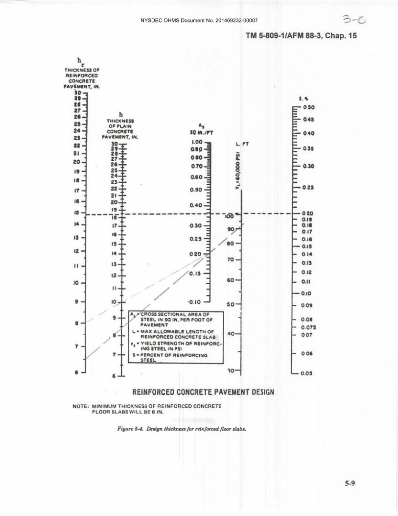
NYSDEC OHMS Document No. 201469232-00007

NYSDEC OHMS Document No. 201469232-00007

NYSDEC OHMS Document No. 201469232-00007

Appendix L
Facultative Pond Capacity Evaluation
NYSDEC OHMS Document No. 201469232-00007

November 2013
UnitCapacity (gallons)
Usable Capacity (gallons)
Fac Ponds 1 / 2 22,881,000 19,345,100Fac Pond 3 51,355,000 43,845,300 Fac Pond 8 43,414,000 38,834,500 Not Used Since 2004Upon Development of RMU-2Fac Ponds 1 / 2 22,881,000 19,345,100Fac Pond 5 24,700,000 21,900,000
Year
SPDES Discharge
Event (gallons)Total Leachate
Processed at AWTSRMU-1 Leachate
(gallons)
RMU-1 Open Area
(Acres)
RMU-1 Final Cover
Events (Acres)
1997 25,614,700 11,120,682 14,079,610 1998 23,986,400 13,889,894 5,924,828 1999 26,272,100 14,699,323 6,785,396 2000 19,046,000 16,646,143 7,490,388 32.61 6.992001 14,116,100 12,078,902 5,887,220 27.49 5.122002 22,271,300 13,405,497 9,282,814 24.47 3.022003 19,595,600 15,594,070 11,970,717 24.472004 19,478,400 18,415,616 16,096,321 24.472005 20,566,200 17,616,353 12,946,527 21.83 2.642006 30,433,600 14,500,137 9,606,283 21.832007 22,632,015 12,553,074 10,520,174 21.832008 15,066,861 14,347,001 11,878,570 21.832009 14,215,564 15,543,238 14,116,427 21.832010 12,846,231 16,194,812 14,666,777 21.832011 18,457,879 18,208,174 15,485,141 11.8 11.22012 14,784,068 10,250,679 8,107,938 11.8
Projected - Year
Projected Discharge
Event (gallons)Projected Total
Leachate Processed
Projected RMU-1 Leachate(gallons)
Projected RMU-1
Open Area(Acres)
Projected RMU-1
Final Cover Events (Acres)
Projected RMU-2
Leachate(gallons)
Projected RMU-2 Open
Area(Acres)
Projected RMU-2
Final Cover Events (Acres)
2013 12,872,899 8,789,333 6,592,000 7.30 4.52014 10,312,899 6,229,333 4,672,000 7.30 2015 12,898,136 8,814,570 2,336,000 - 7.3 4,274,927 6.7 -2016 16,294,354 12,210,788 1,041,925 - 8,116,167 12.7 -2017 15,776,897 11,693,331 653,832 - 8,116,167 12.7 -2018 20,657,763 16,574,197 349,331 - 12,081,317 18.9 -2019 20,465,624 16,382,058 205,227 - 12,081,317 18.9 -2020 20,534,725 16,451,159 257,053 - 12,081,317 18.9 -
RMU-2 CELL APPROXIMATE OPEN WASTE AREA
CELL # (ACRES)CUMULATIVE
ACRES20 5.79 6.718 5.42 12.719 5.35 18.917 5.42 24.616 7.07 30.915 8.2 37.3
Assumptions:1.) A conservative maximum volume of 640,000 gallons per open acre per year of landfill was used for projecting leachate generation rates for active landfill.2.) 4.5 acres of RMU-1 final cover will be installed in 2013 and the remaining cover installed in 2015 and 2016.3.) 75-percent of the wastewater processed at the AWTS is from an active landfill.4.) Cell construction is anticipated to start in 2014 with the first cell open at the beginning of 2015 (best case scenario).5.) Leachate generation rates for entirely capped/closed RMU-1 estimated based on the actual leachate generated from SFL-12 upon closure in 1995.6.) The installation of final cover for RMU-2 will not be performed until the fourth cell is needed.7.) Usable capacity Fac Ponds 1&2 and Fac Pond 5 are pond capacities with 2-foot of freeboard.
Conclusion: Fac Ponds 1&2 and Fac Pond 5 have sufficient capacity to store sitewide processed wastewater for development of RMU-2 through a minimum of the first three cells. It should be noted that this evaluation only assesses one SPDES discharge from the fac ponds per year. The SPDES permit allows for more than one discharge per year.
Fac Pond Capacity EvaluationElimination of Fac Ponds 3 & 8
Construction of Fac Pond 5
Objective: To verify that the capacity of existing Fac Ponds 1&2 and New Fac Pond 5 are sufficient for storage for development of RMU-2.
Data: SPDES Discharges from FAC Ponds, AWTS volume of wastewater processed, and RMU-1 Leachate Generation Rates
NYSDEC OHMS Document No. 201469232-00007