Embed Size (px)
Citation preview

ÍContents ❚ Menu ❚ IndexÎ
EST
NEW LIFT Know how
We lift you upwhere you belong.
ManualOnline

Introduction
ÍContents ❚ Menu ❚ IndexÎ
About this manual
Welcome to NEW LIFT, the innovative lift controller ma-nufacturer. Your decision to purchase one of our quality products opens up completely new electronic horizons.
Our product documentation provi-des an introduction to your new controller and detailed information on the facilities available to you.
Conventions employed
The manual is structured to enable you to familiarize yourself with the controller step by step in the sequence of the chapters, and to find answers to spe-cific questions with the help of the index.
Points of particular importance are marked as follows:
C A U T I O NInformation marked "CAUTION" relates to a risk of accident which could cause physical injury or damage to property.
THIS INFORMATION MUST BE READ.
N O T E
Information marked "NOTE" relates to working procedu-res and product characteristics. These points include comments on factual information, explanations of ter-minology, and tips on making procedures more straight-forward.
This Online Manual supports hypertext references to other locations in the book. You can easily select an link by
double-clicking the blue styled text.
Return again with keys „CTRL“ + „–“. Test it now:
1 Overview of the EST
Operation of the menu is also described in the sequence in
which the levels are encountered. The individual interme-diate menu items are not displayed, e.g.:
MAIN MENU > INFORMATION > ORIENTATION DRIVE
Menu items can be recognized by the use of CAPITAL LETTERS and the > menu arrow (see “1 Overview of the EST”).
The status of the controller can be read in the operator dis-play, which appears for example as follows:
Program versions
Our products are subject to continual improvement and furt-her development; specifications may therefore differ slight-ly from those described in the manual. The version of the program loaded can be displayed by the controller (see „4.4 The INFORMATION menu > INFO“), an important item of information which enables you to familiarize yours-elf with the possible settings.
Unless otherwise indicated, the technical specification of controllers corresponds to that applicable on the date of de-livery. We reserve the right to make technical modifications without express notice.
We would be glad to hear constructive suggestions with re-gard to our controllers and the documentation.
NEW LIFT wishes you the best of success with your new controller.
service
INsPEcTION

EST Manual, Edition 05–96 Contents–1
Content
1 Overview of the EST 1–11.1 An innovative decision 1–1
1.2 EST Product characteristics 1–1
1.2.1 Compact, safe, compatible 1–11.2.2 Easy operation 1–11.2.3 Drive programs 1–21.2.4 The heart of the controller 1–21.2.5 Data exchange made easy 1–2
1.3 Technical components 1–3
1.3.1 The motherboard 1–31.3.2 All the components at a glance 1–4
2 Fitting and installation 2–12.1 Scope of delivery 2–1
2.2 Shaft requirements Magnet copying 2–2
2.2.1 Mechanical shaft switches 2–22.2.2 Commissioning 2–22.2.3 Shaft copying, general 2–22.2.4 Deceleration distances 2–32.2.5 Lifts with closed-loop control 2–32.2.6 Shaft positioning (selection) 2–4
3 Operation 3–13.1 Operating personnel requirements 3–1
3.2 Basic concepts 3–1
3.3 Switching the controller on and off 3–2
3.4 Operator keypad and operator display 3–2
3.5 Use of the control menu 3–3
4 Configuration and control com-mands 4–1
4.1 Factory settings 4–1
4.2 Configuration requirements 4–1
4.3 Notes on the Reference Section 4–2
4.4 The INFORMATION menu 4–3
4.5 The CUSTOMER SERVICE menu 4–5
4.5.1 The SETTING sub-menu 4–6
4.6 The CONFIGURATION menu 4–12
4.6.1 The BASIS CONFIG sub-menu 4–13
4.7 Protection against unauthorised access 4–18
4.7.1 Principles 4–184.7.2 Possible passwords 4–184.7.3 Setting the PASSWORD 4–194.7.4 MENU LOCK 4–194.7.5 Access with the password activated 4–19
4.8 Configuration by means of the EST EDIT PC configuration program 4–20
4.8.1 New functions 4–204.8.2 Installing EST EDIT 4–204.8.3 Operation 4–20
������ ❚ Menu ❚ IndexÎ

Contents–2
5 Commissioning and drives 5–15.1 Preconditions for commissioning 5–1
5.2 Installation drives 5–1
5.3 Orientation drives 5–2
5.4 Normal drives 5–2
5.5 Test drives 5–3
5.5.1 Initiating test drives 5–35.5.2 Standard test drive 5–35.5.3 Lock doors 5–45.5.4 Testing TCM drive time monitoring 5–45.5.5 Testing the shaft final limit switches 5–45.5.6 Leaving the test drive menu 5–4
5.6 Short floors 5–5
5.6.1 Short floors at terminal landings KO/KU 5–55.6.2 Short floor at any floor 5–65.6.4 Configuring short floors 5–85.6.5 Measuring drive with short floor 5–85.6.6 The shaft table 5–9
5.7 Parking 5–10
5.7.1 During parking 5–105.7.2 Activating parking 5–115.7.3 Restarting the internal Park timer 5–115.7.4 Statistical parking floor 5–115.7.5 Time-triggered parking floor 5–11
6 Group mode 6–16.1 Principles of group mode 6–1
6.2 Group mode adjustment 6–1
6.2.1 Setting the call handover time 6–26.2.2 Setting the door time 6–26.2.3 Floor offset 6–3
6.3 The group operator display 6–3
6.4 Group faults 6–4
6.4.1 The group processor 6–4
7 Further functions 7–17.1 Adjusting the doors 7–1
7.1.1 Door times diagrams 7–17.1.2 Reversing time 7–27.1.3 Photocell extension 7–3
7.2 Direction reservation 7–4
7.3 Door test during inspection 7–5
7.4 Fireman service control, fire mode and eva-cuation 7–6
7.4.1 Setting in the menu 7–67.4.2 Fire mode control (evacuation) 7–77.4.3 Fireman service mode: Swiss standard
(TRA200, SIA 370/10) 7–77.4.4 Fireman service mode, Hong Kong
standard mode 7–8
7.5 Drive time control monitoring (TCM) 7–9
7.5.1 Configuring the TCM 7–107.5.2 Resetting the TCM 7–10
7.6 Anti-nuisance 7–10
7.7 Maintenance intervals 7–11
7.7.1 Activation of maintenance intervals 7–117.7.2 Deactivation of
maintenance intervals 7–117.7.3 Resetting flashing indicator, starting new inter-
val 7–11
8 Technical Data 8–18.1 ECONOMY CONTROLLER EST 8–1
8.1.1 Safety circuit voltage 8–18.1.2 Signal voltage 8–18.1.3 Electronics supply voltage 8–18.1.4 Man-machine interface 8–18.1.5 Basic design 8–18.1.6 Features 8–18.1.7 Options 8–28.1.7 Dimensions EST 8–28.1.9 Drive programs 8–2
������ ❚ Menu ❚ IndexÎ

Contents–3
9 Faults and troubleshooting 9–19.1 Basic concepts 9–1
9.2 The fault memory 9–1
9.2.1 Displaying the fault memory 9–19.2.2 Saving faults prior to switching off 9–29.2.3 Clearing the fault memory 9–2
9.3 Displayed fault information 9–2
9.3.1 Fault numbers 9–29.3.2 Program module 9–39.3.2 Date and time 9–39.3.3 Additional info 9–3
9.4 Detailed fault information 9–3
9.4.1 Operating system faults 9–39.4.2 Faults in call acquisition 9–49.4.4 Shaft selector and relevelling faults 9–69.4.5 Door and drive faults 9–7
9.5 Events 9–7
9.6 Systematic troubleshooting 9–8
9.6.1 Filling the troubleshooting line 9–89.6.2 Internal data 9–89.6.3 External data (ports) 9–9
9.7 Systematic troubleshooting of shaft selec-tor faults 9–9
9.7.1 Positioning signals 9–99.7.2 Displayed copy signals: 9–109.7.3 Internal positioning counter 9–10
10 Extended configuration for advan-ced users 10–1
10.1 Debug mode 10–1
10.1.1 Cold start 10–110.1.2 RES EVENTS 10–110.1.3 STOP EVENTS 10–110.1.4 EVENTS 10–110.1.5 Debug RAM display 10–110.1.6 Debug task info 10–110.1.7 EEPROM directory 10–210.1.8 EEPROM clear 10–210.1.9 Park drive 10–2
10.2 System start messages 10–3
10.3 Menu CONFIGURATION > BASIS CONFIG > SYS1 10–4
10.4 Menu CONFIGURATION > BASIS CONFIG > SYS2 10–4
10.5 Menu CONFIGURATION > BASIS CONFIG > SYS3 10–5
10.6 Menu CONFIGURATION > BASIS CONFIG > SYS5 10–5
10.7 Menu CONFIGURATION > BASIS CONFIG > SYS4, SYS6, SYS7 10–6
10.8 Menu CONFIGURATION > BASIS CONFIG > SERIAL 10–6
10.9 Menu CONFIGURATION > BASIS CONFIG > DOOR TYPE 10–7
10.10 Menu CONFIGURATION > BASIS CONFIG > SHORT FLOOR 10–8
10.11 Menu CONFIGURATION > BASIS CONFIG > FIREMAN SERVICE 10–8
10.12 Menu CONFIGURATION > BASIS CONFIG > FIREMAN FLOOR 10–9
10.13 Extended fault signals 10–10
10.13.1 Terminology 10–1010.13.2 Additional Error Messages for
II-a Positioning 10–10
10.14 Terminal Connections 10–11
10.14.1 Terminal Connections 230 V-signals X100 10–11
������ ❚ Menu ❚ IndexÎ

Contents–4
10.14.2 Terminal Connections 24 V-Signals X200 10–11
10.14.3 Terminal Connections 24 V-Signals X201 10–11
10.14.4 Terminal Connections 24 V-Signals X202 10–12
10.15 Connector Pin Assignment 10–14
10.15.1 Pin Assignment Drive Program Connector X210 25-way D-SUB 10–14
10.15.2 Connector RS-232 serialX701 9-way D-SUB 10–15
10.16 Seriel Cabels 10–15
10.16.1 Cabel EST <--> PC 10–1510.16.2 Cabel EST<--> EST Group (GST) 10–15
10.17 Expansions 10–16
10.17.1 Pin Assignment Expansion Connector EWG X401 16-way D-SUB 10–16
10.18 Pin Assignment Drive Program X710 (VVVF)25-way D-SUB 10–17
10.19 Legend 10–17
10.19.1 Components 10–1710.19.2 Fuses 10–1710.19.3 Overview 10–18
11 General installation instructions 11–1
11.1 EMC requirements on the installation of controllers 11–1
11.2 Components required 11–1
11.3 Control cabinet overview 11–2
11.3.1 ESTDesign type A: Hydraulics, Star/Delta,2 automatic car doors 11–2
11.3.2 EST Design type B: Hydraulics, Softswitch, else like Design type A 11–3
11.3.3 EST Design type C: Rope, Frequency regula-ted, 2 automatic car doors 11–4
11.4 Fitting the EST controller in the control ca-binet 11–5
11.5 Assembly of the hydraulic EST controller 11–9
11.6 Assembly of the traction EST controller 11–9
������ ❚ Menu ❚ IndexÎ

EST Manual, Edition 05–96 Page 1–1
-
h
e ly ith for
nd re -
-nd
1 Overview of the EST
1.1 An innovative decision
Switchgear in today´s elevator systems is inconceivable wi-thout the use of intelligent hardware and software. This teamwork between switchgear and the lift controller is deci-sive for the time required for installation and maintenance of lift systems.
NEW LIFT provides innovative control technology which can be adapted to the widely varying requirements of diffe-rent customers and countries. All controllers can be opera-ted from the local display, a laptop computer, or by remote diagnostics via a modem. We place great emphasis on the ease of installation and reliability of our products.
The technical concept of the controller is based on a combination of hard-ware and software com-ponents with clear advantages for long-term use.
■ RS 232 interface ena-bles the controller to be fully configured and accessed both lo-cally and by remote data communications; can be used as a group connection.
■ Ergonomic operator keypad ensures precise operation; operator guidance, status texts and information provided in plain text in the local language.
■ All labour-intensive connections, such as the shaft bus, EWG and trailing cable, are made on plug-in terminal blocks, thereby permitting rapid exchange in the event of repair.
■ Up to 16 landings with one-button control, or 11 landings with two-button control.
1.2 EST Product characteristics
The EST controller is designed for use with traction lifts, and with hydraulic lifts utilizing the adjustable fine levellingfacility.
The EST controller is suitable for speeds up to 2 m/s.
1.2.1 Compact, safe, compatible The preselection function, which conforms to EN-TRA-SIA-ÖNORM standards and which drives the drive motor contac-tors, is integrated into the mo-therboard. The control cabinet istherefore compact and clearly arranged. An additional plug-in
travel program board is required only for installations witclosed-loop control.
The controller is supplied with 10 V/ 1 A electronics voltagand 24 V/3 A signal voltage from an external power suppunit. Its standardized signals make the EST compatible wa number of KST subassemblies, resulting in advantageslogistics and compatibility.
1.2.2 Easy operation The Man-machine interface comprises the LCD screen afive control buttons. All controller states and messages adisplayed in plain text: the safety circuit, the controller status, copy signals, drive counter and drive direction, floor status, the next destination floor and the time.
System settings and inputs can be configured flexibly onsite. Help programs and help texts make commissioning amaintenance straightforward.
ÍContents ❚ Menu ❚ IndexÎ

Page 1–2 1 Overview of the EST
en-
to
has s
ci-
1.2.3 Drive programs The drive programs are set via the keyboard according to the drive type. An additional drive program board is only requi-red for special drives (regulated drive installations). All available drives can be controlled by means of this techno-logy.
1.2.4 The heart of the controller The central processing unit of the EST has a clock frequcy of 12 MHz and 2 Mbit of memory. To protect them against power failure, an EEPROM is also provided in which all system parameters are written.
The controller is designed for two door drives and 16 landings with one-button control, or 11 landings with direction-sensitive two-button collective con-trol.
1.2.5 Data exchange made easy A laptop computer, a PC or a modem can be connectedthe serial interface. Up to 4 EST controllers can be net-worked through a group processor. The group processor 5 interfaces through which the connected EST controllerand a monitor or modem are accessed.
The full range of configuration and remote diagnostics falities is then available to the user.
ÍContents ❚ Menu ❚ IndexÎ

EST Manual, Edition 05–96 Page 1–3
1.3 Technical components
1.3.1 The motherboard
3
4
5
6
7
8
9
10 11 12
14
13
No. Description
1 X100 Terminal safety circuit
2 X200 Power supply 230 V
3 Pre-selection
4 X201 Copying, inspektion, SHS
5 X202 Floor display
6 X203 Doors
7 X204 Car calls
8 X205 Shaft calls
9 X210 Socket for drive programs
10 IC-16 Configuration EEPROM
11 IC-15 EST program EPROM
12 X701 RS 232 serial connector for connection to PC, modem or GST group prozessor
13 24 V driver
14 X222 Extension
ÍContents ❚ Menu ❚ IndexÎ

Page 1–4 1 Overview of the EST
- :
1.3.2 All the components at a glance Together with the EST controller, NEW LIFT offers a proven peripheral program by means of which the controllercan be extended to form a tailor-made system if required
Assembley EST accessory Description Producer
A1 Controller board EST NEW LIFT
A2 Power supply 24 V / 3A, twistable PCLC243 FEAS
A3 Drive programs■ Controlled by frequency / voltage■ Behringer / ELRV
FPx NEW LIFT
A4 Inspection cabinet with or without terminals INSP NEW LIFT
A5 Auxiliary power supply units with battery manage-ment (charging and discharging) monitored by regula-tors for all standard capacities and 6, 12 and 24 volts
HSG NEW LIFT
A6 Safety circuit according to EN 81/TRA 200, which meets the requirements for advance-operation doors and relevelling
SHS NEW LIFT
A9 Module supports floor display, gong and departure arrows for the shaft
EWG NEW LIFT
Floor display for straightforward integration of deci-mal and binary inputs; with ASCII character set
EAZ NEW LIFT
Pre-assembled magnet sensor console, which simpli-fies shaft installation
KOPSET NEW LIFT
A10 autonomous group processor, which combines up to 4 ESTs to form a quattro group; GST includes an addi-tional port for external monitoring or modem
GST NEW LIFT
ÍContents ❚ Menu ❚ IndexÎ

EST Manual, Edition 05–96 Page 1–5
X100
A1
X210
X701
X202
X203
X204
DoorsShaft
EWG
X201
X205HSG
INSP
X200
KOPSET
A5
A9
Groupctrl GST
Car push-button
Driveprogram
A3
A10
A4
230 VPower supplyunit A2
EAZ
Auxiliarycontrol
SHSA6
Motordrive
ControllerA7
230 V
ÍContents ❚ Menu ❚ IndexÎ

EST Manual, Edition 05–96 Page 2–1
e d N
in-
re al he
l-
s e in n
2 Fitting and installation
2.1 Scope of delivery
The technical specification of the customer’s order forms the basis of the scope of delivery. The electrical data of the equipment to be connected must conform to the controller.
Before faults are assumed in the controller, ensure that sui-table electrical equipment has been selected.
N O T E
No liability shall be accepted, either for the equipment itself or for related control functions, if equipment which has not been approved by NEW LIFT is operated with the controller.
The scope of delivery includes:❚ Circuit diagrams describing the controller ❚ Delivery report ❚ Brief instructions
Notes on the circuit diagrams
Basic knowledge of electrical engineering and knowledgof the operation of lifts are required in order to understanthe circuit diagrams supplied. The diagrams conform to DIstandards.
Circuit boards are depicted as locks with the appropriateput and output terminals.
The safety switches to be fitted within the safety circuit adependent upon the type of lift and the applicable nationregulations; it is assumed that the customer is aware of trequisite provision of safety switches. Safety switches shown in the circuit diagram but not required for the instalation in question must be bridged at the terminals in thecontrol cabinet as appropriate.
Terminals which are not required remain free. Door drivewith final limit switches which are connected directly to thdoor controller are an exception: the terminals provided the inspection cabinet for this purpose must be bridged ithis case (see “Note to Sheet 1” on the circuit diagram).
ÍContents ❚ Menu ❚ IndexÎ

Page 2–2 2 Fitting and installation
nd ty ui-
m r-
ter-ot
to tch y : e
are ati-g
-sily
up to
2.2 Shaft requirements Magnet copying
This section provides an overview of the necessary shaft switches and shaft copies, the positions of the magnets in re-lation to the drive speed, and the distance between the shaft magnets and the landings.
2.2.1 Mechanical shaft switches Mechanical shaft switches are positive-action roller swit-ches operated by a switching cam. The switches themselves are always installed in a fixed position in the shaft following adjustment, whereas the actuators (switching cams) must be fitted to the mobile part of the lift system, specifically the lift car in the case of traction lifts and the yoke of the hydraulic piston in the case of hydraulic lifts.
Shaft switches include emergency limit switches, inspec-tion drive limit switches, and pre-limit switches. Emergency limit switches are used in all cases in traction lifts; inspec-tion and pre-limit switches are used in certain coun-tries on-ly, according to the applicable regulations governing lifts.
At speeds upwards of 1.2 m/s, mechanical pre-limit swit-ches are fitted together with closed-loop speed control as an additional safety feature. The system thereby monitors at the terminal landings whether deceleration is actually initiated (see circuit diagram for each installation).
2.2.2 Commissioning Operation of the deceleration control must be checked du-ring commissioning, and the sensitivity adjusted. Emergen-cy limit switches, pre-limit switches and inspection drive limit switches must remain actuated during the complete drive from the start of actuation by the switching cam until the buffer is reached, where appropriate.
2.2.3 Shaft copying, general Lift control systems always require signals to decelerate aalign the car. Type EST controllers use bistable proximiswitches for this purpose, i.e. one actuating magnet is reqred to energize and one to de-energize the switch.
F O R FA U L T -F RE E O P E R AT I O NThe distance between the switch and the ma-gnet must not be less than 8 mm or greater than 12 mm as the car passes.
Recommended distance 10 mm.
Offset switches (S33 and S34) are employed at the bottoand top in order to correct the direction and detect the teminal landings.
These switches also serve to initiate deceleration at the minal landings. Upwards and downwards switches are ntherefore required for the terminal landings.
When the magnet has been passed in the drive directionthe terminal landing in question, the associated offset swiremains switched on, and may be switched off again onlonce the terminal landing has been left again. (Exceptionshort floor at one of the terminal landings. In this case, thoffset switch must be interrupted once during levelling. Note the pulse plan of the controller supplied.)
Magnets for offset and door zones (for levelling or or finelevelling with the door open) must be bolted in place. At 1.2 m/s and above, additional mechanical roller switches employed for offset in order to ensure automatic deceleron at the terminal landings in the event of a magnet failinto switch.
The OFF/ON control state of each proximity switch is displayed on the display, and enables faults to be traced ea(see “9 Faults and troubleshooting”). Proximity switch checks can be read clearly only during inspection drive atto 0.8 m/s. At higher speeds, the LCD display is too slowprovide accurate information.
ÍContents ❚ Menu ❚ IndexÎ

EST Manual, Edition 05–96 Page 2–3
d be-h e
i-o
for e
2.2.4 Deceleration distances The deceleration distances are dependent upon several fac-tors, including the speed and load. The values given below can therefore serve only as guide values for the distance from the actuating magnets to the landing..
R E Q U I S I T E A C C U R A C YThe deceleration distances must be the same at each landing. In installations with closed-loop control, in particular, an accuracy of ±10 mm must be ensured..
2.2.5 Lifts with closed-loop control For lifts employing closed-loop control, it must be ensurethat the magnet actuates the level switch at least 50 mmfore the landing. This applies to the level switches in botdirections of drive, i.e. for the upwards proximity switch inthe UP direction and the downwards proximity switch in thDOWN direction.
Before the closed-loop control is commissioned, the proxmity switches must be fitted precisely in position in order tavoid faults during commissioning. The magnets must becorrected again once the control has been adjusted.
Lifts with closed-loop control:Phase controls (thyristor controllers) are employed here closed-loop control of lifts. A description of adjustment ofthe controller has to be lead through corresponding to thcontroller manufacturer´s instructions.
Sp
eed
[m
/sec
]
Tra
ctio
n l
ift
[m]
Tra
ctio
n l
ift
wit
hcl
ose
d-l
oo
p c
on
tro
ll[m
]
Hy
dra
uli
c li
ft[m
]
0,35 0.40 - 0.40
0,45 0.50 - 0.50
0,60 0.60 0.70 0.60
0,80 0.85 0.90 1.10
1,00 1.25 1.20 1.40
1,20 - 1.50 -
1,40 - 2.00 -
1,50 - 2.40 -
1,60 - 2.60 -
1,70 - 3.00 -
1,80 - 3.20 -
2,00 - 4.10 -
ÍContents ❚ Menu ❚ IndexÎ

Page 2–4 2 Fitting and installation
al-aft si-n
UP
ing
ui-
The following information must be available before the controller can be commissioned and adjusted:❚ Intended drive speed❚ 4- or 6-pole motor, i.e. synchronous 1000 or 1500 rpm❚ Pulse generator or tacho-generator on the motor❚ If pulse generator is supplied: number of pulses
The procedures necessary for setting these parameters can be found in the drive controller documentation.
2.2.6 Shaft positioning (selection) 5 (6) tracks are required in the lift shaft for positioning:
■ UP, DOWNUp/down pulses trigger start of initial deceleration for the next landing and provide position monitoring in con-junction with LEVELLING A/B
■ A, B LEVELLINGLevelling A/B positions (B only with installations with fine levelling)
■ KO, KUTop correction, bottom correction: initiation of decelera-tion at the terminal landings
The correction tracks must be bistable, i.e. the signal beco-mes active when correction is entered and remains active up to LEVEL, and becomes inactive when the correction track is left.
The copy program counts the flanks from the position sen-sors on each track. The signals are evaluated on the UP, DOWN and ALIGNED tracks. The KO track is evaluated at the same time during upward drive, and the KU track during downward drive.
The counters are initialized during orientation drive, syn-chronized (see “5.3 Orientation drives”), and stored when the system is switched off. The count is loaded automaticly when the system is switched on. The position in the shat any time can be calculated exactly by means of the potion counter in conjunction with the instantaneous directiocount.
Whereas the KO/KU/UP/DOWN track in the shaft may overlap, the aligned positions must be unambiguous (no or DOWN parallel to LEVELLING).
KO levelled and KU levelled are an exception. Unambi-guous positions can be calculated from the counts, includwith changes in direction in the shaft (e.g. during inspec-tion). Calculation in advance is also possible, and any reqsite short floor can therefore be achieved.
N O T E
The majority of copying faults can be attributed to ma-gnet or sensor bounce, or failure to switch. In order to simplify troubleshooting, a troubleshooting line can be called up in the operator display (see “9.6 Systematic troubleshooting”).
ÍContents ❚ Menu ❚ IndexÎ

EST Manual, Edition 05–96 Page 3–1
nt of on-e-
sary
un-
inst
3 Operation
3.1 Operating personnel requirements
The manual is intended for skilled personnel specially trai-ned in the installation, repair, maintenance, and in particular commissioning of lift systems installed in accordance with TRA or EN81.
C A U T I O NSafe installation and commissioning requires that personnel be familiar with the safety in-structions contained in this documentation and with the acci-dent prevention regulations appli-cable at the site of installation of the lift sy-stem, and that they be able apply these instructions and regulations.
3.2 Basic concepts The EST program system comprises: ❚ The read-only program code in the EPROM;
❚ A configuration in the EEPROM.
Whereas changes to the program necessitate replacemethe EPROM, the system can be adapted to different envirments (new door times, for example) on-site from the oprator keypad, or from a PC by means of remote data transmission. Settings can be changed as often as necesand stored in the EEPROM.
They remain stored, even in the event of a power failure, til they are overwritten as required.
In addition to the settings, the controller can be used for a range of functions and measu-res such as test functions whichsupport maintenance and ser-vice, or operational functions which may be required peri-odically, such as ORIENTA-TION DRIVE.
All settings and functions are called up from the main menu, and can be protected agaaccidental or unauthorized access (see “4.7 Protection against unauthorised access”).
ÍContents ❚ Menu ❚ IndexÎ

Page 3–2 3 Operation
-of
u is
s:
pe-d
3.3 Switching the controller on and off
C A U T I O NBefore switching on, ensure that the controller is con-nected properly .
When it is switched on, the controller performs a self-test. Check the two LED operating voltage displays during this test:
❚ 5 V: General operating display. Indicates that the compu-ter is operating.
❚ 24 V: Computer is operating and has enabled 24 V to the power supply.
The operating status is signalled in the display, e.g.:
3.4 Operator keypad and operator display
Open the front cover of this manual and refer to the information on the control menu, which provides an overview the control button functions.
When the controller has been switched on, the main menalways accessed by
ENTER (middle key).
A help text can be called up for each menu item as followPress the à and Ä keys simultaneously.
Open the back cover and refer to the information on the orator display, which will enable you to recognize the lift ancontroller states.
lock cont.close
tcm
131245
00 09:50
ÍContents ❚ Menu ❚ IndexÎ

EST Manual, Edition 05–96 Page 3–3
e
3.5 Use of the control menuAll settings of the EST controller are performed using the five control buttons described on the fold-out page.
Perform a setting as follows
> Select the setting
> Set the new value
> Save the new value as appropriate in the permanent EEPROM, so that it is retained in the event of a powerfailure.
Use of the menu using time and date as an example
Use of the control menu is described below in stages, using TIME and DATE as an example. This setting procedure is suitable for this purpose as it can easily be ascertained whe-ther all steps produce the desired result.
The time is displayed in the bottom left-hand corner of the operator display. It serves as a basis for a number of inter-nal, time-related functions, such as logging of malfunctions. The display is accurate to one minute. The date is not dis-played.
Proceed as follows:1. Locate the desired function in the menu overview of th
fold-out page, and ascertain its menu path.
2. Access to the main menu: Press the ENTER key.The main menu appears::
3. Switch to the INFORMATION menu level using the  key. The first item of the INFORMATION MENU (TCM RESET) appears:
4. Press the  key several times to reach the SET TIME function; press then the YES à key for configuration.
main menu
information
information
tcm reset
SET TIME
SET TIME
00:12:44
ÍContents ❚ Menu ❚ IndexÎ

Page 3–4 3 Operation
, but
ps
iar r re
5. Position the cursor using the Á/Â keys, and set the time by means of the Ã/Ä keys.
6. Complete the setting procedure using the ENTER key. The following prompt appears:
7. Select YES or NO using the Ã/Ä keys.
8. Terminate the setting procedure by means of the ENTER key:
❚ The setting is stored permanently by means of YES Ã;
❚ The setting procedure is aborted without saving by me-ans of NO Ä.
Setting the DATE
To set the date, proceed in the same way as steps 1 to 4use the  key to switch on to the SET DATE function.
This use of the menu is indicated in abbreviated form in each case in the manual:MAIN MENU > INFORMATION > SET DATE
To set and save the date, proceed in a similar way to ste5 to 8, “Setting the time”.
When you have completed these steps, you will be familwith basic operation of your controller. The procedure foconfiguring the controller is similar to the above proceduand is described in the next chapter.
SET TIME
SET ACTUAL TIME?
no
set date
set date
19.04.95
ÍContents ❚ Menu ❚ IndexÎ

EST Manual, Edition 05–96 Page 4–1
gu-at t-
n or e.
4 Configuration and control commands
4.1 Factory settings
The basic configuration is factory-set in accordance with the technical specification of the order. Changes are not normal-ly required in this menu.
Certain settings in this menu cannot be made from the op-erator keypad, such as “Situation of the doors”. These set-tings can however be made on-site from a laptop computer by means of the EST Editor program (see “4.8 Configuration by means of the EST EDIT PC configu-ration program”).
4.2 Configuration requirements
The basic controller settings are stored in the basic confiration. The controller automatically disables the car drive the beginning of the configuration dialog before these setings are changed.
A condition is however that the car has no drive jobs. If aattempt is made to access the configuration during a drivewith a drive job active, the drive is first allowed to complet
C A U T I O NYou are strongly advised to take the controller out of drive mode when the lift is stationary; this can be achieved, for example, by locking landing calls manually. The BASIS CONFIG dialog must not be started until all passengers have left the car.
The status of the installation is always safe when the controller has been taken out of nor-mal drive mode, i.e. when it is in AUXILIARY or INSPECTION mode.
N O T E
The configuration menu cannot be reached with the controller in EMERGENCY STOP PRIO rity (FIRE) mode.
ÍContents ❚ Menu ❚ IndexÎ

Page 4–2 4 Configuration and control commands
he is
g.
y e
.
s
.:
u
ee
4.3 Notes on the Reference Section
All items in all controller menus are described sequentially in this chapter in the order in which they are encountered when the menus are paged through. In order to use the refe-rences effectively, the user must be familiar with operation of the EST controller (see “3 Operation”).
The Reference Section contains information specific to the menu item stated previously: the start of each description is marked in bold together with the menu marker >, e.g.:
SERVICE > ADJUSTMENTS > START MONITOR
The Reference Section contains information specific to tmenu item stated previously: the start of each descriptionmarked in bold together with the menu marker >, e.g.:
> START MONITOR An explanation of the term is provided in capital letters, e.
MONITORING OF CAR MOVEMENT FOLLOWING THE START COMMAND
A comprehensive explanation or particular instruction mathen follow. “Setting range” and “Step interval” refer to thrange of values which may be entered, e.g.:
❚ Setting range: 5-10 sec❚ Step interval: 1 sec
If the setting range is numeric, the à key increases the valueby the step interval, and the Ä key reduces it by the same interval.
The setting range is indicated together with its units, e.gsec, m/s, etc. If no unit is given, the value refers to inci-dences, e.g. frequency of occurrence before a function itriggered.
The references refer to one or more related subjects, e.g
❚ Reference 1: > TCM RESET (referring to a related menitem, as in this case)
❚ Reference 2: Fault TA-136 Set starting time expired (s“Section”, “Description”)
ÍContents ❚ Menu ❚ IndexÎ

EST Manual, Edition 05–96 Page 4–3
e-
-n-).
n F/
e
4.4 The INFORMATION menu > TCM RESETRESET OF THE ACTIVATED DRIVE TIME MONITOR
The same effect is achieved by switching the main switch off and back on. TCM RESET is also possible in the TEST menu, for example following a TCM TEST.
The function is executed when any key is pressed.
Reference 1: “7.5 Drive time control monitoring (TCM)”Reference 2: > TCM TIME
> FAULT DISPLAYOUTPUT STORED FAULTS
The stored faults are listed in the operator display together with the time, date and floor.
Page through the list using the Á/Â keys. Return to the standard operator display using the ENTER key.
Reference: “9.3 Displayed fault information”
> STORE FAULTSSAVE THE FAULTS PREMATURELY IN THE EEPROM
The fault log is normally stored in the EEPROM at mid-night. This function should be used to secure the fault log immediately before the installation is switched off.
Press the YES Ã or NO Ä key.
Reference: “9.2.2 Saving faults prior to switching off”
> ORIENTATIONSTART ORIENTATION DRIVE
Orientation drive compares switching points (signals) in-stalled in the shaft with the controller configuration, and gnerates shaft information.
YES Ã starts orientation drive;NO Ä returns to the standard operator without effect.
Reference 1: “5.3 Orientation drives”Reference 2: “9 Faults and troubleshooting”Reference 3:> SHAFT TABLE
> LANDING CALL OFFDISABLE LANDING BUTTONS
This is one of several means of disabling the landing buttons. When this function is active, the corresponding “Lading call enable” terminal is inactive (see circuit diagram
The disabled status is indicated by an “x” in line 4, colum10 of the operator display. Switching the main switch OFON re-enables the landing calls.
If the controller is part of a group, this function removes thcar from the group.
YES Ã disables landing callsNO Ä enables landing calls
Reference: “6.1 Principles of group mode”
ÍContents ❚ Menu ❚ IndexÎ

Page 4–4 4 Configuration and control commands
> DOOR LOCKLOCK DOORS
This function is used, for example, during INFORMATION or adjustment work to prevent passengers from entering the car. The controller remains fully operational with the excep-tion of the doors.
C A U T I O NBefore activating this function, ensure that there are no passengers in the car.
If the doors are locked, the complete operator text is written in small characters as an indication. Switching OFF/ON cancels the door lock.
YES Ã locks the doors; NO Ä enables the doors again.
> SET TIMERESET SYSTEM CLOCK
The time which can be set in the controller has two functions:a) Indication that the computer is operational b) Forming the basis of time-dependent functions
The controller has a software-driven clock with date. The seconds count is generated in the controller processor. The clock cannot therefore continue to run when the controller is switched off. The instantaneous time is stored when the con-troller is switched off, and the clock begins to run again with this time when the controller is switched back on.
N O T E
The controller time must be reset again following a po-wer failure or deactivation.
Perform settings using the Ã/Â/Ä/Á keys; return to the normal operator display using the ENTER key.
Reference: “3.5 Use of the control menu”
> SET DATE
RESET DATE
Use the à key to increase and the Ä key to reduce the values. Leave the menu using the ENTER key.
Reference: “3.5 Use of the control menu”
set date
set date
19.11.95
ÍContents ❚ Menu ❚ IndexÎ

EST Manual, Edition 05–96 Page 4–5
lls dif-
l-pe-ill
rs he
> STATISTICSDISPLAY INTERNAL DRIVE STATISTICS
The controller keeps a statistical record of the drive frequen-cy in relation to the floors and the origin of the calls (car but-tons, landing buttons and park drive). These statistics form the basis of “statistical park drive”.
The statistical record is output in the form of a list showing each floor and the associated journeys.
The Á/Â keys can be used to page through the list. Return to the standard operator using the ENTER key.
Reference: “5.7 Parking”
> SHAFT TABLEDISPLAY POSITIONING INFORMATION
The shaft signals read in during orientation drive are stored and output in list form. This function is useful for troubles-hooting during initial installation, for example for checking whether all shaft signals have been read in (switched) in the correct sequence.
Use the Á/Â keys to page through the list. Return to the standard operator using the ENTER key.
Reference 1: “2.2.3 Shaft copying, general”Reference 2: “9.7 Systematic troubleshooting of shaft sel-ector faults”
> INFODISPLAYS INTERNAL PROGRAM INFORMATION
This display provides information on the current program version and the EEPROM of the specific system.
NEW LIFT therefore reserves the right to modify and not to document the content of this screen in future.
Press any key to return to the standard operator display.
4.5 The CUSTOMER SERVICE menu ■ ADJUSTMENT(see “4.5.1 The SETTING sub-menu”)
> AUTOTESTCALL UP AUTO TEST DRIVE MENU
Places the controller in a mode in which automatic car caare generated. These calls can be generated according toferent criteria.
The calls are generated continually until CALLS OFF is caled up in the test drive menu. The controller has normal orating status during the test calls, i.e. “normal” calls are stpossible from the car or landings.
> SERVICE INTERVALSET SERVICE INTERVAL
The service interval can be specified both in operating houand in drives. Select the desired interval type in line 3 of toperator display using the  RIGHT key.
Setting range:0 ... 1000 operating hoursStep interval:1 hour
Setting range:0 ... 65000 drivesStep interval:1000 drives
Use the à key to increase and the Ä key to reduce the valu-es. Leave the menu using the ENTER key.
Reference: “7.7 Maintenance intervals”
> COUNTER RESETCLEAR THE INTERNAL DRIVE COUNTER
Press the YES Ã or NO Ä key.
ÍContents ❚ Menu ❚ IndexÎ

Page 4–6 4 Configuration and control commands
o-
r
urt- the t
”
> FAULT RESETCLEAR THE INTERNAL FAULT MEMORY
N O T E
All stored faults that may be required for troubleshooting will be lost.
Press the YES Ã or NO Ä key.
> STATISTICS RESETCLEAR THE INTERNAL STATISTICS MEMORY
Press the YES Ã or NO Ä key.
Reference: “> STATISTICS”
> DEBUG DISPLAYLINE 2 OF THE OPERATOR DISPLAY BECOMES INFORMATION CHANNEL
The desired information channel can be selected using the Ã/Ä keys.
Use the Ã/Â/Ä/Á keys to perform settings. Use the ENTER key to return to the standard operator display.
Reference: “9.6 Systematic troubleshooting”
N O T E
The following special functions are not available during troubleshooting: ❚ Call to top floor (Ã key)❚ Call to bottom floor (Ä key)
4.5.1 The SETTING sub-menu
> SAFETY DEBOUNCEDELAYS STARTING WHEN THE SAFETY CIRCUIT IS CLOSED FOR THE FIRST TIME
This function prevents a bouncing lock from initiating a mtor stop shortly after starting.
Setting range: 0,0 ... 2,5 secStep interval: 0,1 sec
Use the à key to increase and the Ä key to reduce the values. Leave the menu using the ENTER key.
Reference: Fault TA-140, “Stopping fault caused by doocontact/lock”
> DOOR LOCK DELAYMAXIMUM DELAY FOR DOOR LOCK
If the car door contact is closed and the door lock fails toclose within the set time, the door is opened again and a fher closing cycle is started. The process is repeated untildoor has closed properly, or until the cam/lock fault counhas expired.
Setting range: 2,0 ... 4,0 secStep interval: 0,1 sec
Use the à key to increase and the Ä key to reduce the values. Leave the menu using the ENTER key.
Reference 1: > DOOR LOCK MAXReference 2: Fault TA-134, “Lock wait time expired” Reference 3: Fault TA-135, “Cam/lock fault count expired
ÍContents ❚ Menu ❚ IndexÎ

EST Manual, Edition 05–96 Page 4–7
n
> TCM TIMEDRIVE TIME MONITORING
If the controller fails to receive a positioning signal during a drive within the time set here, drive-time monitoring is acti-vated and the car is stopped, i.e. the next floor must be rea-ched within the time set here.
This status can be cancelled manually only by switching OFF/ON, or from the controller keyboard.
Setting range: 1 ... 45 secStep interval: 1 sec
Use the à key to increase and the Ä key to reduce the values. Leave the menu using the ENTER key.
Reference 1: > TCM RESETReference 2: “7.5 Drive time control monitoring (TCM)”Reference 3: Fault TA-137, “Set time expired”
> START MONITORCAR MOVEMENT MONITORING FOLLOWING THE
START COMMAND
Monitoring begins when the safety circuit is closed. If the car fails to leave the level position within the set time, the car is stopped (level switch switched off within the shaft range).
The shutdown is cancelled by means of the TCM RESET function or by switching OFF/ON.
Setting range: 5 ... 10 sec Step interval:1 sec
Use the à key to increase and the Ä key to reduce the values. Leave the menu using the ENTER key.
Reference 1: > TCM RESETReference 2: Fault TA-136, “Set starting time expired”
> CONTACTOR MONMONITORS THE CLOSED CIRCUIT OF THE DRIVE CONTACTORS (CONTACTORS STATIONARY)
If a failure occures, TCM releases. Only for export or wheconstructed according to EN81 (Plan group X100, terminal 113).
Switch the function ACTIVE using the à key, and OFF using the Ä key.
Reference 1: > TCM RESETReference 2: Fault TA-129, “Contactor monitoring fault inrest state”
> STAR/DELTASTAR/DELTA STARTING (VALVE PILOT CONTROL WITH SOFT STARTING)
;Can be set with hydraulic drives only.
Setting range: 0,02 ... 5,0 secStep interval: 0,02 sec
Use the à key to increase and the Ä key to reduce the values. Leave the menu using the ENTER key.
> MOTOR OFF DELAYMOTOR SWITCH OFF POINT DELAYED FOR HYDRAULIC LIFTS
;Can be set with hydraulic drives only.
Setting range: 0,02 ... 5,0 secStep interval: 0,02 sec
Use the à key to increase and the Ä key to reduce the values. Leave the menu using the ENTER key.
ÍContents ❚ Menu ❚ IndexÎ

Page 4–8 4 Configuration and control commands
at
if a
if a
> SPEED CHANGE DLYDRIVE CONTACTORS CHANGEOVER TIME
Delays the changeover from FAST to SLOW and back on traction lifts without closed-loop control.
Setting range: 0,02 ... 5,0 secStep interval: 0,02 sec
Use the à key to increase and the Ä key to reduce the values. Leave the menu using the ENTER key.
> CAM DELAYDELAYS DROP-OUT OF THE DOOR LOCK CAM BY THE SET TIME WHEN THE LEVEL OR DOOR ZONE SWITCH IS REACHED
; Is active and can be set with manual doors only.
Setting range: 0,0 ... 4,0 secStep interval: 0,1 sec
Use the à key to increase and the Ä key to reduce the values. Leave the menu using the ENTER key.
Reference: > MANUAL DOORS
> DOOR OPEN DELAYDELAYS OPENING OF THE CAR DOOR BY THE SET TIME WHEN THE LEVEL OR ZONE SWITCH IS REACHED
Setting range: 0,0 ... 4,0 secStep interval: 0,1 sec
Use the à key to increase and the Ä key to reduce the values. Leave the menu using the ENTER key.
> MIN WAIT CARMINIMUM WAIT TIME AT THE FLOOR
This time is evaluated as the starting delay when the carlands following a car call. Starting is thereby delayed by least this duration, even if a command is present.
When this time has elapsed, the car door begins to closelanding call is present.
Setting range: 0 ... 60 secStep interval: 1 sec
Use the à key to increase and the Ä key to reduce the values. Leave the menu using the ENTER key.
> MIN WAIT LANDINGMINIMUM WAIT TIME AT THE FLOOR
This time is evaluated as the starting delay when the carlands following a landing call. Starting is thereby delayedby at least this duration, even if a command is present.
When this time has elapsed, the car door begins to closelanding call is present.
Setting range: 0 ... 60 secStep interval: 1 sec
Use the à key to increase and the Ä key to reduce the values. Leave the menu using the ENTER key.
> LAND CALL ENABLELANDING BUTTON ENABLE DELAY FOLLOWING INSP, PRIO
Setting range: 0 ... 30 secStep interval: 1 sec
Use the à key to increase and the Ä key to reduce the values. Leave the menu using the ENTER key.
ÍContents ❚ Menu ❚ IndexÎ

EST Manual, Edition 05–96 Page 4–9
up ar ne
ge
> CAR CALL PRIODIRECTION PRIORITY WITH LANDING CALLS
Should the car loose its direction during landing, the drive direction of the calling push-button is assumed for the dura-tion set here. Callers can therefore issue their desired desti-nations on the car push-button losing the direction to another landing call.
This is an important time for group optimisation. It is mea-sured from the level time.
Recommended setting: one door OPEN/CLOSED cycle.Setting range: 0 ... 30 secStep interval: 1 sec
Use the à key to increase and the Ä key to reduce the values. Leave the menu using the ENTER key.
> FAULT SEND DELAYSHOULD THE CAR FAIL TO START WITHIN THIS TIME FOLLO-WING A COMMAND, A START FAULT IS SIGNALLED TO THE FAULT SIGNALLING OUTPUT
This fault is typically triggered by the failure of a door to close. The car is not shut down, i.e. the car is available again as soon as the fault is cleared.
The time begins running as soon as the command is issued, i.e. possibly with the door open. The function is therefore in-dependent of the START MONITOR setting.
With group configurations, the car is removed from the group at this point at the latest.
Setting range:1 ... 20 min Step interval:1 min
Use the à key to increase and the Ä key to reduce the values. Leave the menu using the ENTER key.
> CALL HANDOVERCALL HANDOVER IN GROUP CONFIGURATIONS
; Active only when group mode is set.
This time is started as soon as a call is issued by the groprocessor. If the time expires without the car starting, the cis taken out of the group and the group call passed on to oof the other lifts by the group processor. An error messais not generated.
Setting range: 0 ... 180 sec (40 sec recommended)Step interval: 1 sec
Use the à key to increase and the Ä key to reduce the values. Leave the menu using the ENTER key.
Reference 1: > FAULT SEND DELAYReference 2: > GROUP MODE
> ANTI NUISANCEPREVENTS UNNECESSARY DRIVE IN THE EVENT OF ABUSE OF THE CAR BUTTONS
; Possible only on installati-ons with photocell or manual door.
Recognition is achieved by comparison of the photocell breaks or manual door operati-ons with the number of car calls.
Setting range: Bottom landing to top landing:❚ Number of floors until the car command is cleared❚ Switches the function off
Use the à key to increase and the Ä key to reduce the values. Leave the menu using the ENTER key.
Reference: “7.6 Anti-nuisance”
ÍContents ❚ Menu ❚ IndexÎ

Page 4–10 4 Configuration and control commands
t .
ly e
> PARKINGACTIVATION OF THE PARKING/HOMING FACILITY
Press the YES Ã or NO Ä key.
Reference: “5.7 Parking”
> PARK TIMETIME UNTIL PARKING (HOMING) IS ACTIVATED
; Adjustment is possible only with PARKING activated.
Setting range: 1...15 minStep interval: 1 min
Use the à key to increase and the Ä key to reduce the values. Leave the menu using the ENTER key.
Reference: “5.7 Parking”
> PARKING FLOORSETS DESTINATION LANDING FOR PARKING
Setting range:0 ... top landing
Use the à key to increase and the Ä key to reduce the values. Leave the menu using the ENTER key.
Reference: “5.7 Parking”
> LIFT-OFF FLOORDETERMINES DRIVE DESTINATION OF LIFT OFF DRIVE
The lift OFF function can be initiated by means of the key-operated switch over shaft cable X400 through terminal X238 (active = 24 V GND). The function can also be acti-vated via the serial interface; the NEW LIFT KSTMON pro-gram is required in this instance.
Setting range: 0 ... terminal floor
Use the à key to increase and the Ä key to reduce the number of floors. Leave the menu using the ENTER key.
> CAR LIGHT OFFDEACTIVATION OF THE AUTOMATIC CAR LIGHT RELAY IN THE IN-SPECTION CABINET/ON TERMINAL X259
When the car doors have closed, thetime here begins to run. When the time has expired, the relay drops ouand the car light circuit is interrupted
The car light is switched back on:❚ When the door or manual door is opened❚ When a command is issued from the floor
Setting range: 0 ... 60 secStep interval:1 sec
Use the à key to increase and the Ä key to reduce the values. Leave the menu using the ENTER key.
> PHOTOCELL EXTENDSTEADYING OF DOOR REVERSING BEHAVIOUR DURING PAS-SENGER ENTRY
With photocell extend set, the photocell remains effectiveconstantly active when interrupted by several people. Thdoor is not reversed during this time.
Setting range: 0,0 ... 10 secStep interval: 0,1 sec
Use the à key to increase and the Ä key to reduce the values. Leave the menu using the ENTER key.
Reference: “7.1.3 Photocell extension”
ÍContents ❚ Menu ❚ IndexÎ

EST Manual, Edition 05–96 Page 4–11
n
re-
> DOOR TIMECONTROLS CALL HANDOVER TO THE GROUP
; Active only with the group configuration switched on.
If photocells, manual doors or door open buttons are active for longer than the time set here, landing calls are not trans-mitted to the EST controller.
Setting range:0 ... 300 sec (15 sec empfohlen)Step interval:1 sec
Use the à key to increase and the Ä key to reduce the values. Leave the menu using the ENTER key.
> DOORREVERSE MAXNUMBER OF PHOTOCELL INTERRUPTION BEFORE NUDGING COMMENCE
Setting range: 0 ... 20Step interval: 1
Use the à key to increase and the Ä key to reduce the values. Leave the menu using the ENTER key.
Reference: “7.1.3 Photocell extension”
> DOOR NUDGE.TIMEPOSITIVE DOOR CLOSING TIME
When this time has expired, the photocell function is de-activated, thereby initiating positive closing of the door
Setting range: 0 ... 300 secStep interval:1 sec
0: De-activates the positive closing function
> DOOR APPROACHPERMITS LANDING WITH THE DOOR OPEN BY ACTUATION OF THE SAFETY CIRCUIT BYPASS RELAY K113
; This function is executed only within valid door zones ithe shaft.
Press the YES Ã or NO Ä key.
Reference: Fault TA-141, “Relevelling fault time-out”
> DOOR PARK STATEDOORS OPEN OR CLOSED AT END OF DRIVE
Press the UP Ã or DOWN Ä key.
(Also applies to park landing.)
> DOOR CHANGE DELAYDELAYED DOOR CONTACTOR CHANGEOVER BETWEEN OPEN AND CLOSED, E.G. WITH INTERRUPTION OF PHOTOCELL DURING CLOSIN
Prevents a short-circuit with three-phase door drive, e.g.sulting from arcing.
Setting range: 0,0 ... 1,0 secStep interval: 0,1 sec
Use the à key to increase and the Ä key to reduce the values. Leave the menu using the ENTER key.
> REVERS TIMEDOOR OPEN HOLDING TIME FOLLOWING RE-OPENING OWING TO INTERRUPTION OF PHOTOCELL
Setting range: 1 ... 20 secStep interval: 1 sec
Use the à key to increase and the Ä key to reduce the values. Leave the menu using the ENTER key.
Reference: > PHOTOCELL EXTEND
ÍContents ❚ Menu ❚ IndexÎ

Page 4–12 4 Configuration and control commands
”
> DOOR OPEN TIMEA DOOR LIMIT SWITCH OPERATION IS SIMULATED WHEN THIS TIME HAS EXPIRED, AND THE MOTOR DE-ENERGISED.
Set values only on doors without limit switches; otherwise set to 99 sec.
Setting range: 1,0 ... 99,0 secStep interval: 0,1 sec
Use the à key to increase and the Ä key to reduce the values. Leave the menu using the ENTER key.
> OPEN HOLD TIMEWHEN THIS TIME HAS EXPIRED, THE DOOR BEGINS TO CLOSE IF THE BASIC SETTING IS CLOSED
Applies only when a drive command is present. If a com-mand is present, the door is closed as soon as the starting delay has elapsed.
Setting range: 2 ... 99 secStep interval: 1 sec
Use the à key to increase and the Ä key to reduce the values. Leave the menu using the ENTER key.
Reference: > MIN WAIT CAR
4.6 The CONFIGURATION menu
■ BASIS CONFIG
(see “4.6.1 The BASIS CONFIG sub-menu”)
> PASSWORDPROTECTION OF CONTROLLER AGAINST UNAUTHORISED ACCESS
Press the YES Ã or NO Ä key.
Reference 1: > MENU LOCKReference 2: “4.7 Protection against unauthorised access
> CALLSON/OFF SWITCHING OF PRE-PROGRAMMED CALLS
> MENU LOCKPROTECTION OF CONTROLLER AGAINST UNAUTHORISED ACCESS
Press the YES Ã or NO Ä key.
Reference: “4.7.4 MENU LOCK”
ÍContents ❚ Menu ❚ IndexÎ

EST Manual, Edition 05–96 Page 4–13
4.6.1 The BASIS CONFIG sub-menu
> DRIVE SYSTEMCONFIGURATION OF MOTOR TYPE
The following types are available:
Select the desired type using the Ã/Ä keys. Leave the menu using the ENTER key.
> DOOR TYPEDOOR TYPE CONFIGURATION
The following types are available:
Select the desired type using the Ã/Ä keys. Leave the menu using the ENTER key.
> MANUAL DOORSDOOR CONFIGURATION WHEN MANUAL SHAFT DOORS ARE FITTED
Press the YES Ã or NO Ä key.
Reference: > CAM DELAY
NO DRIVE2-SPEED TRACTIONLOHER DCLASCRSTGIEHLLEISTRITZOILDYNAMIC1-SPEED TRACTIONBERINGER ELRVLRV FEINNACHST.F.UMRICHT..LM.FSVGIEL-FEINNACHST.ZETADYN-1DV / 1DFMICOTROL-330 / 320 / 340DYNAVERT-LDYNATRON-S
PROGRAMMABLE, e.g. for special doorsMEILLER SPINDELKIEKERTWITTUR 3201WITTUR RC24SEMATIC LMDC2010SIEMENS AT10RIEDL RTKI.G.V.RATHGEBER PUFFERAS8081
ÍContents ❚ Menu ❚ IndexÎ

Page 4–14 4 Configuration and control commands
e. n.
> DOOR DECOUPLINGNUMBER OF FAILED COUPLING CYCLES OF A SPINDLE DOOR BEFORE THE INSTALLATION IS RESET; ALL CALLS ARE CLEA-RED, BUT THE CAR IS NOT SHUT DOWN
; Setting possible only when door type = PROGRAMMA-BLE. Value 3 is set automatically with other door types.
Setting range: 1 ... 100: Deactivate function
Use the à key to increase and the Ä key to reduce the values. Leave the menu using the ENTER key.
Reference:Fault TA-133, “Decoupling counter expired”
> DOOR LIMIT SW
DOOR CONFIGURATION: DOOR WITH LIMIT SWITCH
; Setting possible only with PROGRAMMABLE door type.
Press the YES Ã or NO Ä key.
> DOOR DEENERGIZEDDOOR CONFIGURATION: DOOR MOTOR DE-ENERGIZED IN REST STATE
; Setting possible only with PROGRAMMABLE door type.
Press the YES Ã or NO Ä key.
> CAR DOOR BUFFERON OLDER DOOR DESIGNS WITH MECHANICAL BUFFER
; Setting possible only with PROGRAMMABLE door type.
Press the YES Ã or NO Ä key.
> DEPARTURE ARROWDEPARTURE ARROWS ACTIVE (ILLUMINATED) WITH DOOR CLOSED
Press the YES Ã or NO Ä key.
> EMERG STOP FNCAR CALLS CLEARED FOLLOWING EMERGENCY STOP; AN EMERGENCY STOP IS GENERATED BY ALL SWITCHES IN THE SAFETY CIRCUIT UPSTREAM OF THE DOOR AND LOCK CONTACTS
Press the YES Ã or NO Ä key.
> EMERG STOP MAXNUMBER OF EMERGENCY STOPS BEFORE THE INSTALLATION IS SHUT DOWN; AN EMERGENCY STOP IS GENERATED BY ALL SWITCHES IN THE SAFETY CIRCUIT UPSTREAM OF THE DOOR AND LOCK CONTACTS
The emergency stops must be generated during one drivShutdown is cleared by means of the TCM RESET functio
Setting range: 1 ... 100: Function off
Use the à key to increase and the Ä key to reduce the values. Leave the menu using the ENTER key.
Reference 1: > TCM RESETReference 2: Fault TA-142, “Emergency stop fault countexpired”
ÍContents ❚ Menu ❚ IndexÎ

EST Manual, Edition 05–96 Page 4–15
s s
f
r
> DOOR INTERR MAXNUMBER OF DRIVE INTERRUPTIONS CAUSED BY LOCK/INTER-LOCK FAULTS DURING A DRIVE BEFORE THE INSTALLATION IS SHUT DOWN
The shutdown is cancelled by means of the TCM RESET function, or by switching the power supply OFF/ON.
Setting range: 1... 100: Function off
Use the à key to increase and the Ä key to reduce the values. Leave the menu using the ENTER key.
Reference 1: > TCM RESETReference 2: Fault TA-143, “Stopping fault count expired”
> DOOR LOCK MAXNUMBER OF DOOR LOCK FAULTS BEFORE CAR AND LANDING CALLS ARE CLEARED
All calls are cancelled, but the car is not shut down. Reasons for the car not being started are for example failure of lock or car door contact to close.
Setting range: 1 ... 100: Function off
Use the à key to increase and the Ä key to reduce the values. Leave the menu using the ENTER key.
Reference: Fault TA-135, “Max. number of door lock faults exceeded”
> GROUP MODEGROUP CONFIGURATION OF LIFTS
Setting range: 1 ... 2550: No group
Use the à key to increase and the Ä key to reduce the values. Leave the menu using the ENTER key.
Reference: “6 Group mode”
> FIREMAN SERVICECONFIGURATION OF FIREMAN SERVICE (FIRE MODE/FIREMAN MODE)
Setting range: 0 ... 255
Use the à key to increase and the Ä key to reduce the values. Leave the menu using the ENTER key.
Reference: “7.4 Fireman service control, fire mode and evacuation”
> FIREMAN FLOORDESTINATION OF FIRE MODE DRIVE
The fireman function can read in the destination floor by means of hardware or software. If the software function iused, the destination floor is taken from the setting in thimenu item.
The door information is coded in the floor by the addition othe following values to the floor:
In this example, the value 136 has been set for door B fodestination floor 8.
Setting range: 0 ... 255
Use the à key to increase and the Ä key to reduce the values. Leave the menu using the ENTER key.
Reference: > FIREMAN SERVICE
> SHORT FLOORSPECIFICATION OF SHORT FLOOR MODE
Use the à key to increase and the Ä key to reduce the values. Leave the menu using the ENTER key.
Reference: “5.6 Short floors”
+64 For door A
+128 For door B
+192 For doors A+B
ÍContents ❚ Menu ❚ IndexÎ

Page 4–16 4 Configuration and control commands
as
as
> FLY TIMELANDING TIME WITH SHORT FLOOR
; Adjustment possible only with SHORT FLOOR
Setting range: 0,02 ... 10,0 secStep interval: 0,02 sec
Use the à key to increase and the Ä key to reduce the values. Leave the menu using the ENTER key.
Reference: “2.2 Shaft requirements Magnet copying”
> ZONE TIMEDOOR ZONE DELAY ON, AFTER STARTING
Setting range: 0,0 ... 10,0 secStep interval: 0,1 sec
Use the à key to increase and the Ä key to reduce the values. Leave the menu using the ENTER key.
> RELEVELLINGFINE LEVELLING OF THE CAR (INCLUDING WITH DOOR OPEN)
;Can be set with hydraulic drives with active RELEVEL-LING only.
Enables exact levelling during relevelling of the exact aligned position.
Setting range: 0,02 ... 2,0 secStep interval: 0,02 sec
Use the à key to increase and the Ä key to reduce the values. Leave the menu using the ENTER key.
Reference: “2.2 Shaft requirements Magnet copying”
> RELEVEL STOPSTOP MOTOR AND VALVE OVERRUN TIME WITH DELAY FOLLOWING LEVELLING
;Can be set only if RELEVELLING is active.
Permits more accurate levelling when the level position hbeen reached.
Setting range: 0.02 ... 2.0 secStep interval: 0.02 sec
Use the à key to increase and the Ä key to reduce the values. Leave the menu using the ENTER key.
Reference:> RELEVELLING
> DOOR ZONE OFFDROP-OUT DELAY OF SAFETY CIRCUIT BYPASS RELAY FOLLOWING RELEVELLING
; Can be set only if RELEVELLING is active.
Permits more accurate levelling when the level position hbeen reached.
Setting range: 0,02 ... 2,0 secStep interval: 0,02 sec
Use the à key to increase and the Ä key to reduce the values. Leave the menu using the ENTER key.
Reference: > RELEVELLING
ÍContents ❚ Menu ❚ IndexÎ

EST Manual, Edition 05–96 Page 4–17
> LANGUAGEOPERATOR DISPLAY SETTING
Setting range:GERMAN, ENGLISH (other languages on demand)
Use the à key to increase and the Ä key to reduce the values. Leave the menu using the ENTER key.
> SERIALSETTING SERIAL INTERFACE
This setting is used for the special configuration, and is pre-set as standard
Setting range: 0 ... 255
Use the à key to increase and the Ä key to reduce the values. Leave the menu using the ENTER key.
Reference: “10.8 Menu CONFIGURATION > BASIS CONFIG > SERIAL”
> SYS1 > ... SYS3 ... > SYS7FACTORY-STANDARD SETTINGS
These settings are special configurations pre-set in the fac-tory.
Setting range: 0 ... 255
Use the à key to increase and the Ä key to reduce the values. Leave the menu using the ENTER key.
References: “10.3 Menu CONFIGURATION > BASIS CONFIG > SYS1” up to “10.7 Menu CONFIGURATION > BASIS CONFIG > SYS4, SYS6, SYS7”
ÍContents ❚ Menu ❚ IndexÎ

Page 4–18 4 Configuration and control commands
4.7 Protection against unauthorised access
4.7.1 Principles Access to the menu or the main menu levels can be protec-ted against unintentional or unauthorised access by entry of a four-digit numeric password.
When a password has been set, it is requested when the pro-tected main menu level is opened. This level cannot be ac-cessed if no password or an incorrect password is entered.
Once the protected level has been opened, it remains open until 00.00 (midnight) or until it is closed again by entry of the password.
The controller is supplied set to “0000”. Protection is not active in this case.
4.7.2 Possible passwords The password always consists of the first three digits, which can be selected freely, and the final digit, which spe-cifies the level(s) to be protected:
Examples of passwords:❚ 1237 consisting of password 123 and protection of all
levels;
❚ 8366 consisting of password 836 and protection of INFORMATION and SERVICE.
0 No protection
1 Protects CONFIGURATION
2 Protects SERVICE
3 Protects CONFIGURATION and SERVICE
4 Protects INFORMATION
5 Protects CONFIGURATION and INFORMATION
6 Protects INFORMATION and SERVICE
7 Protects CONFIGURATION, SERVICE and INFORMATION
8 No protection
9 Protects CONFIGURATION
ÍContents ❚ Menu ❚ IndexÎ

EST Manual, Edition 05–96 Page 4–19
Le-ible ns
a-
e
ng
4.7.3 Setting the PASSWORD
K E E P T H E P A S S W O R D I N A S A F E P L A C E
Once the password has been set, it may not be possible to access the CONFIGURATION level without entry of the password. The password cannot thereafter be changed or reset.
> Call up the following in turn in the main menu:CONFIGURATION > PASSWORD
The current password appears, e.g.:
0000 means: No password
>Write the desired password down.
> Using the Á/ keys, position the password over the re-quired digit. Then use the à key to increase and the Ä key to reduce the values.
> Repeat this procedure for all digits until the desired pass-word has been entered.
> Leave the menu using the ENTER key.
If the subsequent prompt, “RESET YES/NO” is acknow-ledged with the YES Ã key, the password is saved. Provi-ded the password is not equal to 0000, it becomes active immediately, and protects the selected level(s).
Keep the password in a safe place, but ensure that it is available to the authorized maintenance personnel.
4.7.4 MENU LOCK A password must be set before this function can be used.vels accessed by means of the password remain accessuntil 00.00. Protection can be restored in advance by meaof the MENU LOCK function.
> Call up the following in turn in the main menu:CONFIGURATION > MENU LOCK
> Press the YES Ã or NO Ä key. Then use the ENTER key to save the setting and leave the menu.
4.7.5 Access with the password activated If a level is protected by a password, the following informtion is displayed when the level is selected::
The figure “0000” must now be overwritten with the pre-viously set password. The cursor is initially located on thfirst digit.
> Use the à key to increase and the Ä key to reduce the values. Confirm the password and leave the menu usithe ENTER key.
password
0000
MENU LOCK
nein
INFORMATION
0000
ÍContents ❚ Menu ❚ IndexÎ

Page 4–20 4 Configuration and control commands
T
n or gh
ce
al
s
r-
pro-
4.8 Configuration by means of the EST EDIT PC configuration program
4.8.1 New functions The EST EDIT configuration program was written to enable you to configure your EST controller on a PC.
This has the following advantages:
■ Data files can be processed more clearly directly on the PC screen.
■ Configurations already present in the EST can be trans-ferred, processed and saved again.
■ Identical data files need only be generated once. They can then be used repeatedly.
■ Data files can be stored safely.
The editor is a DOS program which an be used on virtually any PC or laptop computer.
It is available directly from NEW LIFT on diskette, and may be copied freely by our customers as shareware. A serial data transmission cable is also required; customers may or-der this cable from NEW LIFT or fabricate it at any time themselves (see “10.16 Serial Cabels”).
4.8.2 Installing EST EDIT The EST Editor can either be started from the diskette or copied onto the hard disk:
> Switch to the DOS operating system level on the PC.
> Insert the EST Editor diskette.
> Change to the disk drive: C:>A:
> Start installation: A:>install A C
Starting the program from the hard disk> Start the editor from the hard disk by entering EST EDI
and pressing the Return key.
The editor does not initially require an ONLINE connectioto the controller. If you wish to transmit or receive data to from the EST, however, a serial link must be set up throuthe COM1 or COM2 interface.
The start help program uses COM2, the standard interfafor most PCs.
4.8.3 OperationThe EST Editor operation is broadly similar to the MS-DOS shell (refer to the Microsoft MS-DOS user manuand reference) or an SAA operator interface:
❚ Issue commands using the Alt key, the alphabetic keyA to Z, the cursor keys and the function keys
❚ Leave menus using the Esc key; call up important infomation with F1
The program can also be operated by means of a mouse,vided the mouse is installed under DOS.
ÍContents ❚ Menu ❚ IndexÎ

EST Manual, Edition 05–96 Page 5–1
5 Commissioning and drives
5.1 Preconditions for commissioning
F O R Y O U R O W N S A F E T Yand in order to avoid unnecessary troubleshoo-ting during commissioning, the following con-ditions must be met before the first drive is performed:
❚ Emergency limit switches fitted, adjusted, and operation tested
❚ Impact buffer fitted
❚ Operational test of inspection drive performed
❚ Operational test performed of all safety circuit switches
❚ Actuating magnets fitted in shaft in accordan-ce with pulse plan
❚ Counterweight balancing performed with 50% load
❚ Ensure that the cabin door blade passes throu-gh with sufficient clearance to the interlock de-feat mechanism
❚ The car door must be closed
❚ In the case of lifts driving at 1.2 m/s and faster and with closed-loop control, the additional mechanical final limit switches must also be fit-ted at the terminal landings in order to ensure monitoring of deceleration at the terminal lan-dings.
5.2 Installation drives The following points must be checked prior to first drive:
■ Rope lengths, undershoot and overshoot■ Stipulated switchgear room height in the shafthead■ Operational test of the safety switches on the car roof■ Adequate deceleration force of the brake■ Shaft access points closed and locked■ Safety catch and speed limiter■ Operational test of the inspection drive pushbutton
C A U T I O N❚ Operation of the deceleration monitor must be checked and tripping of the monitor set du-ring commissioning. Emergency limit switches, pre-limit switches and inspection limit switches must remain actuated for the complete drive from the beginning of actuation by the cam up to possible impact with the buffer.
❚ An increased risk of accident is always entailed during an installation drive. The local accident prevention regulations must be observed.
❚ Installation drives may be performed only with the inspection drive facilities fitted for the purpose on the car roof.
N O T E
After an inspection drive, normal operation is only pos-sible following the opening and closing of the safety cir-cuit (fitter steps down from car). If the car is levelled, normal operation is available immedeately.
ÍContents ❚ Menu ❚ IndexÎ

Page 5–2 5 Commissioning and drives
:
it-
l-n r m
5.3 Orientation drives
The orientation drive compares the fitted switching points (signals) in the shaft with the configuration of the control-ler, and generates the internal information table for posi-tioning. The car also measures and records the drive times between all floors.
Should a discrepancy be detected during orientation drive, a fault message is output. Discrepancies include missing or superfluous pulses. In the event of a fault, a question mark appears in column 1, line 4 of the operator display.
An orientation drive is normally required only once, when the controller is started for the very first time. A drive com-mand without a valid orientation drive automatically results in an orientation drive being started.
Proceed as follows to initiate orientation drive:
> In the main menu, call up the following functions in turnINFORMATION > ORIENTATION DRIVE
”ORIENTATION DRIVE” flashes on the operator displayduring orientation drive. If the controller subsequently swches automatically to normal mode, orientation drive hasbeen completed successfully.
Malfunctions arising during orientation drive are shown flashing.
N O T E
Orientation drive must be differentiated from correc-tion drive, which always has the next terminal floor as its destination, e.g. following fatal positioning errors.
If short floor is configured according to the shaft, a measuring drive is performed when the orientation drive has been completed (see “5.6.5 Measuring drive with short floor”).
Reference:“5.6.6 The shaft table”
5.4 Normal drives
An orientation drive must always be initiated by the controler as the first drive. Only when orientation drive has beecompleted properly and without malfunctions may furthenormal and test drives be initiated from the machine rooor the pushbuttons on the car and landing panels.
N O T E T O F I R S T D R I V E
The door should be prevented from opening during the first drive by switching off the door drive.
Reference 1: “5.5.3 Lock doors”Reference 2: 4.4 The INFORMATION menu > DOOR LOCK
ÍContents ❚ Menu ❚ IndexÎ

EST Manual, Edition 05–96 Page 5–3
lay
st
u
al
5.5 Test drives
Test drives are used for the performance of inspections by the licensing authorities, or for commissioning the lift.
In contrast to normal drives, for which call commands are issued from the landing or car panels, test drives are always initiated from the controller. Calls are issued from a test drive menu which is called up on the operator display.
The menu operates parallel to normal operation of the con-troller. When the menu is activated, test drives can also be performed concurrent with normal drives.
The following test drive types are possible:
■ DRIVE: Standard test drive sets car call in the target floor■ TCM: Test drive with activation of test time monitoring
(TCM) after approx. 3 seconds■ FINAL LIMIT SWITCH: Test drive to final limit
switches
In addition, the door(s) can be locked with all test drive types. Locking is cancelled automatically when the test drive menu is left.
The menu display encompasses columns 10 to 16 and lines 3 and 4. All other information on the operator display remains displayed.
The test drive menu appears directly in the operator dispand is started by means of the  key:
test=5 Signals destination floor 5DRIVE Signals “DRIVE” test type
The test drive menu flashes during the display to signal temode.
5.5.1 Initiating test drives The following inputs can be made whilst the test drive menis flashing:
> Select the test drive type using the Á/Â keys: DRIVE; TCM; LIMIT SW; DOOR; OFF> Enter the destination floor using the Ã/Ä keys> Initiate test drive using the ENTER key
The different test drive types are then displayed.
5.5.2 Standard test drive
Drives can be initiated from the machine room with this drive type. The drive is initiated as a car call and is identicto a normal drive.
test=5
DRIVE
test=5
DRIVE
ÍContents ❚ Menu ❚ IndexÎ

Page 5–4 5 Commissioning and drives
o-si-
t is i-
o-
Further test drives can be initiated whilst the drive is in pro-gress. These are stored, acknowledged and executed as car calls.
5.5.3 Lock doors
To lock out undesired passengers, the doors can be locked prior to execution of the test drive:
> Press the à key: lock doors> Press the Ä key: enable doors
Line 1 is then displayed small during the test drive to signal that the doors are locked.
Any test drive type desired can be selected concurrent with this function; the “LOCK DOORS” function remains active.
The doors are enabled again automatically when the test drive menu is left.
5.5.4 Testing TCM drive time monitoring
For this function, a drive destination is selected and initi-ated as for a standard test drive. The internal TCM time is overwritten with approx. 3 secs for this test. This results in a TCM monitoring error being triggered and the car being
shut down when the time has expired. When drive time mnitoring has been initiated (TCM flashes), resetting is posble immediately by pressing the ENTER key.
5.5.5 Testing the shaft final limit switches
The destination of this drive is the topmost or bottommosfloor. The controller executes a normal drive until the carin the level position, at which point it ignores the level postion and moves the car at slow speed to the final limit switch.
During final limit switch test drive:
> The à key sets the KO floor (topmost floor)> The Ä key sets the KU floor (bottommost floor)
During the final limit switch test drive, the ENTER key must be pressed as soon as the function is initiated and held down until the car has reached the final limit switch psition (dead man function).!
5.5.6 Leaving the test drive menu
The test drive menu can be left in test drive type OFF bypressing the ENTER key.
test=0
door
test=0
tcm
test=0
LIMIT SW
test=0
off
ÍContents ❚ Menu ❚ IndexÎ

EST Manual, Edition 05–96 Page 5–5
a-L r
e
5.6 Short floors
If the interval between two floors is too small to bring the car to a halt owing to the speed V2 and the required decel-eration distance, the landing magnet for the destination floor must be set back by the requisite distance.
This means for example that the DOWN landing magnet for floor 1 is located between floors 2 and 3, and that there is no longer a DOWN magnet between floors 2 and 1. In this case, the interval between 1 and 2 is a short floor.
FIG: SHORT FLOOR IN THE SHAFT
5.6.1 Short floors at terminal landings KO/KU For a short floor at the KU terminal landing, the landing mgnet for floor 1 would have to be placed below the LEVEposition of floor 0. This is of course impossible; a short floodrive must therefore be performed from floor 0 to floor 1 and vice-versa.
> In this case, the landing position for floor 0 (KU track) must be placed before floor 1.
The requirements for:❚ BISTABLE KU track and ❚ Unambiguity of the LEVEL positionmean that the KU track for the LEVEL [1] position must bbroken.
> In this case, three magnets, from the top downwards:NORTH - SOUTH - NORTH required for correction at thebottom:
FIG.: SHORT FLOOR AT KU
LEVEL 0 1 2 3
UP 1 2 3
DOWN 1 2
KU 0
Floor [0]Floor [1]
Floor [2]Short floor
UP
Floor [3]
DOWN
LEVEL 0 1 2
UP 2
DOWN 1
KU 0
Floor [0] Floor [1]
Short floor
UP
Floor [2]
DOWN
ÍContents ❚ Menu ❚ IndexÎ

Page 5–6 5 Commissioning and drives
to d
B I S T A B L E E X P L A N A T I O N
The proximity switch is switched on in the UP direction by the south pole of a magnet and switched off on the same track in the DOWN direction by the north pole of a second magnet.
This principle also applies to the top floor (KO short floor).
5.6.2 Short floor at any floor During short floor drives, the car starts with speed V1 and switches to speed V0 at the deceleration point V0 (applies only to installations with closed-loop control). In this case, the first UP position is assigned to floor 2.
FIG.: SHORT FLOOR AT ALL FLOORS
The deceleration point is determined by the time intervalthe LEVEL stop and will be stored as FLY TIME. Proceeas follows:
> Call up the following in turn from the main menu: CONFIGURATION > BASIS CONFIG > FLY TIME
> Use the à key to increase and the Ä key to decrease thetime values [msec]. Leave the menu using the ENTER key.
N O T E
No additional magnet track is required for switching off the intermediate speed V1.
LEVEL 0 1 2 3
UP 42 3
1 2
0
Floor [0] Floor [1] Floor [2]
3 short travels
UP
Floor [3]
DOWN
0
DOWN
KU
ÍContents ❚ Menu ❚ IndexÎ

EST Manual, Edition 05–96 Page 5–7
-r
in t
5.6.3 Automatic zone suppressionThis function is available only if the function “PRE-OPENING DOORS” has been selected (see “> DOOR APPROACH”). This function is illustrated by the following example:
A short floor drive is performed from floor 1 to floor 2. The UP landing magnets for floor 1 and 2 are therefore both ahead of floor 1.
FIG.: SUPPRESSED ZONE
During a drive from 0 to 2, floor 1 is therefore crossed during landing, in the process of which the door zone of floo1 is detected.
The zone up to floor 1 must be suppressed automaticallythis instance in order to prevent the door from opening afloor 1. A prerequisite for this is a zone gap between floor 1 andfloor 2, as shown in the diagram.
Suppressed zone
Resulting zone
LEVEL 0
Direction of drive
1
UP
Landing
2 3
1 2 3
Zone
ÍContents ❚ Menu ❚ IndexÎ

Page 5–8 5 Commissioning and drives
r n-t
n-
rt
. -
ati-
-
s
5.6.4 Configuring short floors To configure short floors, proceed as follows:
> Call up the following in turn from the main menu:CONFIGURATION > BASIS CONFIG > SHORT FLOOR
> Select one of the following settings::
“Shaft” is synonymous with “somewhere in the shaft, at least once”; KU = Bottom correction (bottommost floor)KO = Top correction (topmost floor)
> Use the à key to increase and the Ä key to reduce the values. Leave the menu using the ENTER key.
5.6.5 Measuring drive with short floor If a short floor is configured, the time behaviour of the caat speed V1 is automatically measured following the orietation drive. The car drives at speed V1 between the nextwo floors for this purpose (the car is accelerated after LEVEL and landed on the next possible floor).
Since the measured V2 times are available from the orietation drive, the time interval from starting at V1 to chan-geover to V0 can be calculated at a later stage for a shofloor.
This applies to any floor with the exception of KU and KOIf short floors are set for these floors, additional measurement drives are performed automatically.
If the drive system settings are re-adjusted, a new orienton drive must also be performed.
“MEASURING DRIVE” flashes on the operator display during the measuring drive(s).
The measuring drives are performed at V2 on installationwithout closed-loop control (without V1).
Basis config.
short floor
1
0 No short floor
1 Short floor(s) in the shaft
2 Short floor in KU
3 Short floor in the shaft + KU
4 Short floor in KO
5 Short floors in the shaft + KO
6 Short floors KU + KO
7 Short floors only
ÍContents ❚ Menu ❚ IndexÎ

EST Manual, Edition 05–96 Page 5–9
5.6.6 The shaft table The shaft table shows the information stored during orienta-tion drive, namely the UP/DOWN magnets and whether they are present between the LEVELLING magnets.
The exact positions are not saved, nor are the relationships between the UP/DOWN magnets to each other, which are essential for the positioning program.
To display the shaft table, pro-ceed as follows:
> Call up the following points in turn from the main menu::INFORMATION > SHAFT TABLE
Line 2 of the operator display indicates the shaft section.
Line 3 indicates the UP and KO magnets in this shaft sec-tion.
Line 4 indicates the DOWN and KU magnets in this shaft section.
> Press the Á/Â keys to move the shaft portion by one floor in each case. An overview is displayed of the mag-nets present in the shaft and the resul-ting conclusions.
Examples
1)
Line 2: Between floors 0 and 1Line 3: UP magnet for floor 1Line 4: KU magnet for floor 0
2)
Line 2: Between floors 1 and 2Line 3: UP magnet for floors 2 and 3Line 4: DOWN magnet for floor 1
shaft table
0 1
1
0
shaft table
1 2
2 3
1
ÍContents ❚ Menu ❚ IndexÎ

Page 5–10 5 Commissioning and drives
a
e this
-
o-ng
r-
ark
ive y n.
3)
Line 2: Between floors 2 and 3Line 3: No UP magnet, Short floorLine 4: No DOWN magnet, Short floor
4)
Line 2: Between floors 3 and 4Line 3: UP magnet for floor 5Line 4: DOWN magnets for floors 2 and 3
Conclusion:
Short floor between floors 2 and 3. Two UP magnets and one DOWN magnet between floors 1 and 2; no magnetsbetween floors 2 and 3 (short floor), and two DOWN ma-gnets and one UP magnet between floors 3 and 4.
5.7 Parking
The controller supports automatically activated parking toparking floor (normally downwards) in accordance with TRA 265.51 .
The PARKING FLOOR and the PARK TIME to activationof parking can be set in steps of 1 to 15 minutes.
If the parking floor is a landing which actually exists in thsystem and the settings described above are employed,is described as standard parking.
If the parking floor setting is greater than the topmost system floor, statistical parking is activated.
Time-driven parking can only be programmed in the factry. In this instance, the car drives to different preset parkifloors during preset times.
If the controller is configured in a group and statistical paking is preselectedt (see “5.7.4 Statistical parking floor”), the car drives to a parking floor determined by the groupcontroller on an hourly basis .
5.7.1 During parking The operator display indicates “PARK/HOMING” during parking. The door is actuated according to the set door pstate when the car lands on the parking floor.
Parking operations can be aborted at any time by new drcommands. The car drives to the new destination floor bthe shortest route, and the direction display is switched i
R E V E R S I N G S T O P
If the new command is in the opposite direction to the parking direction, the car lands on the next possible floor. The door remains closed and the car drives to the floor from which the call originated.
shaft table
2 3
shaft table
3 4
5
2 3
ÍContents ❚ Menu ❚ IndexÎ

EST Manual, Edition 05–96 Page 5–11
o:
he -
y
y
n-
d n
r. e
-
5.7.2 Activating parking A number of settings must be performed:
■ Switch on PARKING> Call up the following in turn from the main menu:SERVICE > ADJUSTMENTS > PARKING
> Set PARKING to ACTIVE using the à key. Leave the menu using the ENTER key.
and
■ PARKING FLOOR> Call up the following functions in turn from the main menu:SERVICE > ADJUSTMENTS > PARKING FLOOR
> Increase the floor value to floor “n” using the à key;reduce the floor value using the Ä key. Leave the menu using the ENTER key.
and
■ PARK TIME> Call up the following in turn from the main menu:SERVICE > ADJUSTMENTS > PARK TIME
> Using the Ã/Ä keys, set the time to parking in minutes. Leave the menu using the ENTER key.
5.7.3 Restarting the internal Park timer Follow the procedure below to reset the park timer to zer
■ Terminate drive
■ Switch the controller OFF/ON
■ Switch the priority controller OFF (auxiliary mode, in-spection mode, fireman service mode, fire mode)
Car relevelling movements do not restart the park timer. Tpark timer is held when the priority controller (auxiliary mode, inspection mode, fireman service mode, fire mode) isswitched on.
5.7.4 Statistical parking floor The controller records landing data in a statistics memorwith each landing. The parking floor can be established from these statistics. The car then selects as the parkingfloor the floor from which landing calls are most frequentlreceived.
The function becomes active when
■ the set PARKING FLOOR is greater than the highest floor in the system; floor 255 is a suitable value in this istance.
■ PARK/HOMING is active and the time, PARK TIME has expired.
The statistical selection of the parking floor can be switcheto parking on a specific programmed floor by selecting aexisting floor.
5.7.5 Time-triggered parking floor This menu setting can only be configured in the EST EditoThe function is of use only in conjunction with the real-timclock.
If parking/homing is ACTIVE and the PARK TIME has expired, the car drives to the set parking floor.
ÍContents ❚ Menu ❚ IndexÎ

Page 5–12 5 Commissioning and drives
-r
ec-of .
ly.
The parking floor driveled to is eithera) The parking floor determined by statistical evaluationb) The parking floor assigned for a specific timec) The single parking floor previously implemented
Parking/homing according to condition b) or c) is not per-formed if statistical parking floor is set.
For condition b), Time-triggered parking floor” to be effec-tive, it must be:
1. Programmed in the EST Editor
2. Switched on (> CONFIGURATION > BASIS CONFIG > SYS1 + 8)
If the time condition set for a specific parking floor is not fulfilled, the car drives to the “basic” parking floor (condition c). A specific time is defined for a specific parking flooas follows:
“Parking floor: Day(s), Hour(s)”
One or more days, for example the entire week, may selted for the day. Any interval or several intervals, in steps one hour, may selected for the hour; the limit is 24 hours
Examples:
08-10 hours, 12-14 hours, 17-22 hours
Up to five parking floors can be determined simultaneousThe EST Editor is used for programming.
ÍContents ❚ Menu ❚ IndexÎ

EST Manual, Edition 05–96 Page 6–1
he T e-
the
id
he l
g to-t
ion
t m-o-
p
ad-
6 Group mode
6.1 Principles of group mode
Group control is undertakten by the GST group processor. Each GST has a serial connection to the EST (interface X701). Calls from landing buttons are presented to all EST controllers in parallel, but are only transmitted from one EST to the GST. This EST has the designation MASTER (MST), all other ESTs are SLAVES (SLV). The promotion to master is selected by the GST on a random basis and can change depending on a situation, e.g. when the master EST is switched to inspection mode.
Each controller processes its car calls normally, but trans-mits its status continuously to the GST and receives selected landing calls from the GST.
The status of a EST comprises its car calls, its position in tshaft, its direction, and its status (inspection etc.). The GScompares the landing calls from all EST controllers, and dcides at the last possible moment which car is to receive call.
The group supports the parking floor of the car with the aof a simultaneous statistics function:
If PARK DRIVE is active in the main menuSERVICE > ADJUSTMENTS > PARK DRIVE
the PARKING FLOOR is set to 255, and the set PARK TIME (1 to 15 minutes) has expired, the group signals to tcar the floor from which landing calls are most frequentlyreceived. This function is performed independently for alcars.
Should a EST fail (fault, external event, etc.), the remaininESTs receive all calls, a new master will be assigned aumatically – no calls are lost. If group communication is lospermanently, each EST independently receives a proportof the landing calls after a brief interval, according to thepreset group mode.
6.2 Group mode adjustment
The group programs always become active when the seGROUP MODE is greater than 0. The group mode is a nuber between 0 and 255, in which three functions are encded:
A Response to landing call enable in the event of a groufault (e.g. communication), (fault: Rd-150)
B Issuing of landing call priority to the ESTs
The numbers of the selected functions A and B must be ded together to produce the setting.
ÍContents ❚ Menu ❚ IndexÎ
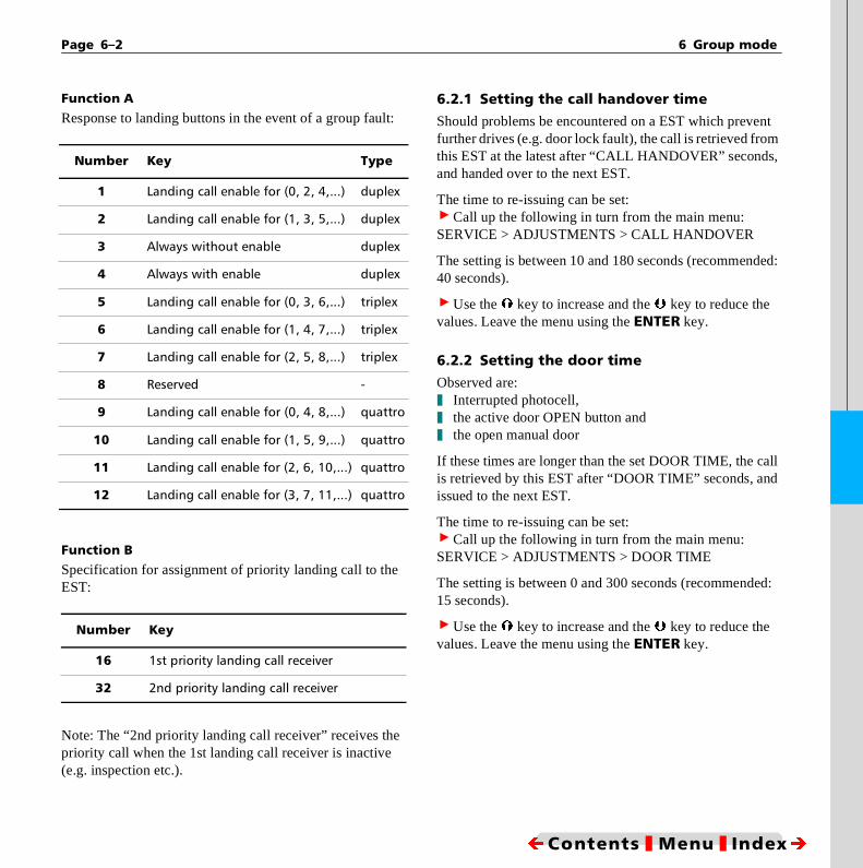
Page 6–2 6 Group mode
nt
,
ed:
all d
d:
Function A
Response to landing buttons in the event of a group fault:
Function B
Specification for assignment of priority landing call to the EST:
Note: The “2nd priority landing call receiver” receives the priority call when the 1st landing call receiver is inactive (e.g. inspection etc.).
6.2.1 Setting the call handover time Should problems be encountered on a EST which prevefurther drives (e.g. door lock fault), the call is retrieved fromthis EST at the latest after “CALL HANDOVER” secondsand handed over to the next EST.
The time to re-issuing can be set:> Call up the following in turn from the main menu:SERVICE > ADJUSTMENTS > CALL HANDOVER
The setting is between 10 and 180 seconds (recommend40 seconds).
> Use the à key to increase and the Ä key to reduce the values. Leave the menu using the ENTER key.
6.2.2 Setting the door time Observed are:❚ Interrupted photocell,❚ the active door OPEN button and❚ the open manual door
If these times are longer than the set DOOR TIME, the cis retrieved by this EST after “DOOR TIME” seconds, anissued to the next EST.
The time to re-issuing can be set:> Call up the following in turn from the main menu:SERVICE > ADJUSTMENTS > DOOR TIME
The setting is between 0 and 300 seconds (recommende15 seconds).
> Use the à key to increase and the Ä key to reduce the values. Leave the menu using the ENTER key.
Number Key Type
1 Landing call enable for (0, 2, 4,...) duplex
2 Landing call enable for (1, 3, 5,...) duplex
3 Always without enable duplex
4 Always with enable duplex
5 Landing call enable for (0, 3, 6,...) triplex
6 Landing call enable for (1, 4, 7,...) triplex
7 Landing call enable for (2, 5, 8,...) triplex
8 Reserved -
9 Landing call enable for (0, 4, 8,...) quattro
10 Landing call enable for (1, 5, 9,...) quattro
11 Landing call enable for (2, 6, 10,...) quattro
12 Landing call enable for (3, 7, 11,...) quattro
Number Key
16 1st priority landing call receiver
32 2nd priority landing call receiver
ÍContents ❚ Menu ❚ IndexÎ

EST Manual, Edition 05–96 Page 6–3
er
6.2.3 Floor offset ; This setting can be configured with the EST Editor only.
Shafts of different lengths can be combined to form a group configuration. The offset is the distance between the shorter shaft and floor [0] of the longer shaft.
Conditions
1. All shorter shafts must be complete sub-set of the longest shaft.
2. The offset of the shorter shaft to the longer shaft must not exceed 7 floors.
3. The shorter shaft must always be SLAVE in the group; this must be taken into account with the setting “1st pri-ority landing call receiver” (Group No. +16).
Normalization
The distance to the shorter shaft can be displayed in norma-lized form in the operator display of the affected EST.
EST begins counting with the offset instead of “0”.
Valid configuration example:
Unvalid configuration example:
6.3 The group operator display
The EST displays its group status by means of a code lettin line 4, column 1 of the operator display.
Display Not normalized Normalized Offset SLV
EST-A 0123456789 0123456789 0
EST-B 01234567 12345678 1 X
Display Not normalized
EST-A 012345678
EST-B 012345678
Value Key
w Waiting: EST waits for group connection (switch on)
M Master: EST with landing call acknowledge-ment
m Single master drives without group controller, other ESTs are out of the group (inspection etc.)
S Slave: EST without landing call acknowledge-ment
p Pending: EST wishes to leave group (inspection etc.)
X Exit: EST has left the group
# EST / GROUP link broken
@ Brief intermediate status
ÍContents ❚ Menu ❚ IndexÎ

Page 6–4 6 Group mode
6.4 Group faults
The following three faults indicate a problem in the link bet-ween the EST and group processor:
RD-130Unknown group commandRD-150Group communication interruptionRD-151Unanticipated master -> slave exchange
In the event of a per-manent group fault, the landing calls wit-hout group processor are issued according to the set group mode.
6.4.1 The group processorThe link to each EST comprises a serial line.
The status of each line is displayed by an LED on the group processor:❚ LED lit continuously: connection to EST present❚ LED flashing: fault or disconnection on corresponding line
If a durable fault occurs, the group prozessor should be re-started with the RESET key; landing calls may be lost.
A PC program can display the group processes schematical-ly via the integral serial interface (group monitor GS MON).
ÍContents ❚ Menu ❚ IndexÎ

EST Manual, Edition 05–96 Page 7–1
Level (S29/S30)
Landing (S31/S32)
Zone enable
Zone
Bypass
Cam
Door open delay
Door OPEN
Starting delay*
Open holding time*
Call command
Door CLOSED
1
1
2
3
4
12
34
Opens during approach
Opens when level
Car starts when command is issued and starting delay time has expired
Doors close when open holding time has expired
* Configurable Menu point in ADJUSTMENTS submenu
Cam delay
1 2
2
1
2
7 Further functions
7.1 Adjusting the doors
7.1.1 Door times diagrams
FIG.: GENERAL DOOR TIMES
ÍContents ❚ Menu ❚ IndexÎ

Page 7–2 7 Further functions
7.1.2 Reversing time On doors without limit switch, the door moves to the OPEN position only if the reversing time is sufficiently long.
On doors with limit switches, the door always moves as far as the limit switch, but does not close until the reversing time has expired.
FIG: DOOR REVERSING TIME
> Call up the following in turn from the main menu:SERVICE > ADJUSTMENTS > REVERS TIME
> Set the reversing time in seconds using the Ã/Ä keys.
> Save the setting by pressing the ENTER key.
Door closed
Photocell
Reverse time
Door open
ÍContents ❚ Menu ❚ IndexÎ

EST Manual, Edition 05–96 Page 7–3
x-
e-d
Door closed
Open holding time
Photocell
Reverse time
Photocell extension
Photocell
Photocell extension
Door open
With several passengers:
7.1.3 Photocell extension In order to hold the door in reversing mode as passengers are entering the car, a photocell extension time is set. Activation of the photocell is extended artificially for this time so that it remains active when passed through by several passen-gers, and the doors do not reverse.
This time does not extend the REVERSE TIME, i.e. the door is not kept open for an excessive time. Accordingly, the REVERSE TIME can be set shorter. We recommend that the magnitude of the REVERSE TIME be selected equal to the DOOR OPEN DELAY (up to 4 seconds).
There is only one time for all doors. To set the photocell etension, proceed as follows:
> Call up the following in turn from the main menu:SERVICE > ADJUSTMENTS > PHOTOCELL EXTEND
> Using the Ã/Ä keys, extend the extension time in sec-onds. We recommend that this time be set to approx. 3 sconds, or a little longer if the lift is used by older or disablepersons (the value 0 cancels this time).
> Save the setting by pressing the ENTER key.
FIG.: PHOTOCELLS
Only interrup-tions which last longer than the time set here cause a closing/reversing opera-tion and initiate the reversing time.
ÍContents ❚ Menu ❚ IndexÎ

Page 7–4 7 Further functions
7.2 Direction reservation
Extension of the car direction by the CAR CALL PRIO time. During this time, a passenger can enter the car and is-sue a car call without another potential passenger on another floor calling the car.
The direction reservation is noted as the car lands. The di-rection reservation time begins from the level point.
N O T E
In groups, the CAR CALL PRIO should always be greater than the STARTING DELAY.
FIG.: DIRECTION RESERVATION FOR CAR COMMANDS
> Call up the following in turn from the main menu:SERVICE > ADJUSTMENTS > CAR CALL PRIO
> Set the direction priority in seconds using the Ã/Ä keys.
> Confirm the setting by pressing the ENTER key.
Door closed
Door open delay
Car command
Door open
Direction
Direction reservation
Starting delay
Actual reservation
ÍContents ❚ Menu ❚ IndexÎ

EST Manual, Edition 05–96 Page 7–5
7.3 Door test during inspection
According to the mode selected, the door(s) can be moved to OPEN or CLOSED for test purposes. The OPEN and CLOSE door buttons must be used for this purpose.
The test cannot be performed if an inspection drive com-mand has been issued. An inspection drive command has priority, and automatically closes the door(s). During the test mode the reversation is switched off.
> Setting:
SYS 2 +4
ÍContents ❚ Menu ❚ IndexÎ

Page 7–6 7 Further functions
n
o-
7.4 Fireman service control, fire mode and evacuation
The system supports an evacuation drive to the main floor, and a fireman service control. Whereas the sole task of eva-cuation drive is to bring the car to a preset main floor and park it there with the doors open, the fireman service control permits operation of the car using the car buttons. A fireman service key-operated switch must be operated in the car for this purpose.
All characteristics described below are transmitted to the controller via the menu. The main floor can be determined in two ways:
A In the landing button shaft cable (this method enables an evacuation switch to be connected in theory on each floor)
B By EST Editor
Which of the two methods is used is determined by the FIREMAN MODE described below.
7.4.1 Setting in the menu All evacuation/fireman settings can be set by combinatioof the following parameters:
Setting example: The number 97 is composed of the follwing partial values:
To carry out the setting, proceed as follows:> Call up the following in turn from the main menu:CONFIGURATION > BASIS CONFIG > FIREMAN SERVICE
> Use the à key to increase and the Ä key to reduce the values. Leave the menu using the ENTER key.
Value Function
0 Main floor is identical to FIREMAN FLOOR
1 Main floor is coded in shaft cable
2 Nicht belegt
4 Evacuation from X255 + MAIN FLOOR
8 Reserved
16 Evacuation automatically becomes fireman drive
32 Fireman standard = Hong Kong (otherwise Switzerland, TRA200 )
64 Door in main floor OPEN (otherwise CLOSED)
128 Fireman service drive can be switched off on main floor only
1 Fireman standard = Hong Kong
32 Main floor is coded in shaft cable
64 Door on main floor OPEN (otherwise CLOSED)
ÍContents ❚ Menu ❚ IndexÎ

EST Manual, Edition 05–96 Page 7–7
is
e
-
i- .
o as
u-
7.4.2 Fire mode control (evacuation) When the fire mode is activated by shaft signal X255 (fire mode key-operated switch), the “fire mode drive” operating mode is set in the controller. All other priority controls with the exception of inspection control and auxiliary control are overridden.
The operator display of the controller signals this condition by flashing “FIRE MODE”. Photocells are deactivated; the controller no longer acknowledges calls, and calls which have already been acknowledged are cancelled.
Affected functions
❚ Landing and car buttons are locked❚ Overload and full load recognition is deactivated❚ Any photocells, sensor strips, etc. are deactivated
Drive to the main access point
The car drives by the shortest route to the main access point and remains there with the doors open.
If the car is at that point driving away from the main access point, it lands on the next possible floor with the doors clo-sed, then drives to the main access point by the shortest route.
If the car is at that point driving in the direction of the main access point, the drive is extended or shortened so that the car lands at the main access point.
The controller reverts to normal mode when fire mode prio-rity is switched off.
7.4.3 Fireman service mode: Swiss standard (TRA200, SIA 370/10)When the fireman key-operated switch at the main floor operated, the car drives directly to the main floor and re-mains there with the doors unlocked and open (TRA266.52). The car and landing buttons are locked (sealso “Fire mode control”).
When the fireman key-operated switch in the car is operated, the controller is set to FIREMAN MODE. All other priority controls, with the exception of inspection and auxliary, are rendered ineffective (TRA 266.55). At the sametime, further drive commands can be issued from the car
If fireman mode is switched on without prior evacuation tthe main access point, the instantaneous floor is enteredthe main access point.
The operator display of the controller flashes “FIREMANMODE” in this status.
Affected functions
❚ Landing and car buttons are locked❚ Overload and full load recognition is overridden❚ Any photocells, sensor strips, etc. are deactivated❚ Priority controls with the exception of inspection and a
xiliary control become inactive
Türmodus
❚ The “CLOSE DOOR” pushbutton is inactive❚ The “OPEN DOOR” pushbutton is inactive
ÍContents ❚ Menu ❚ IndexÎ

Page 7–8 7 Further functions
a-
at er-
R
ed re-
ar
re--h
Car buttons
The car buttons are enabled for commands; the first car but-ton pressed activates a drive command.
If the fireman switch is switched ON/OFF, the car com-mand is cleared (TRA 266.52(2) ). If the switch is switched ON/OFF during drive, the car command is cleared and the car lands on the next possible floor. A safety circuit inter-ruption during drive does not clear the car command.
Eine Sicherheitskreis-Unterbrechung während der Fahrt löscht das Innen-Kommando nicht!
N O T E
Car commands can only be issued if the fireman key-operated switch is switched on.
Switching off fireman mode
If partial value 128 is active in the “FIREMAN MODE” set-ting, the “FIREMAN MODE” can only be switched off at the main floor. Operation of the fireman key-operated switch in all other positions only has the effect of clearing any car commands; the operating mode is retained.
7.4.4 Fireman service mode, Hong Kong standard modeWhen the fireman key-operated switch in the car is operted, FIREMAN MODE is set.
When the fireman switch is operated for the FIRST TIME a point other than the main floor, an evacuation drive is pformed to the main floor (as described for “7.4.2 Fire mode control (evacuation)”).
The operator display of the controller flashes “FIREMANMODE” in this status.
Affected functions
❚ Landing and car buttons are locked❚ Overload and full load recognition is overridden❚ Any photocells, sensor strips, etc. are deactivated
On the main floor:
❚ Door basic setting during landing: as programmed
On other floors:
❚ Door basic setting during landing CLOSED
Door control
The car buttons and the CLOSE DOOR and OPEN DOObuttons are active as described below:
❚ In the car status DOOR OPENThe CLOSE DOOR pushbutton closes the door, providit remains pressed. The door opens when the button isleased. The door remains closed if the CLOSE limit switch is active.
All car buttons have the same function as the CLOSEDOOR button. No drive commands are accepted fromthe car buttons.
❚ In the car status DOOR CLOSEDThe car buttons are enabled for commands: the first cbutton pressed initiates a drive command.
The OPEN DOOR button opens the door, provided it mains pressed. The door closes when the button is released. The door remains open if the OPEN limit switc
ÍContents ❚ Menu ❚ IndexÎ

EST Manual, Edition 05–96 Page 7–9
e w
g
re-o-ed
is active, or if the DOOR OPEN TIME has expired on doors without limit switch.
❚ In the cars status DRIVEFurther car commands can be issued to shorten the drive. All acknowledgements and commands are cleared upon landing.
If the fireman switch is pressed again, all car commands are cleared and the car lands on the next possible floor.
Switching off the fireman drive
The “Fireman mode” can be configured such that it can be switched off only on the main floor. In all other positions, operation of the fireman key-operated switch only has the effect of clearing any car commands: the operating mode remains unaffected.
A drive can however be performed only with the signal active (key).
7.5 Drive time control monitoring (TCM)
The controller supports drive time control monitoring ac-cording to TRA 262.621(1). When the motor is started, thpresence of the positioning signals is monitored. Each nepositioning signal restarts the drive time control monitorinwith the full monitoring time.
When the car is started, the next positioning signal mustach it within the set drive time. If this time elapses, the mtor triggers an emergency stop, and the controller is lockfor normal drives. This status is displayed by “TCM” flashing on the operator display of the controller.
N O T E
A TCM is activated when the START MONITOR monito-ring time expires (to EN 81).
ÍContents ❚ Menu ❚ IndexÎ

Page 7–10 7 Further functions
t is is-
he
7.5.1 Configuring the TCM The time required for activation of the TCM can be adju-sted. Any time setting greater than 0 seconds switches the function on. The presetting is 45 seconds.
> Call up the following in turn from the main menu:SERVICE > ADJUSTMENTS > TCM TIME
> Use the à key to increase and the Ä key to reduce the values. Leave the menu using the ENTER key.
7.5.2 Resetting the TCM When shut down by the TCM, the installation can be reac-tivated by one of the following procedures:
> Call up the following in turn from the main menu:MAINTENANCE > TCM RESET
> Press the YES Ã key.
❚ or switch the controller OFF/ON
❚ or switch the auxiliary switch ON/OFF
❚ or switch the inspection switch ON/OFF
7.6 Anti-nuisance
The car can be protec-ted against use of the car buttons for nu-isance drives. The ac-tive photocell and manual doors are ta-ken into account for this function.
If the car has received a drive command from an internal pushbutton and the photocell or manual doors are not activated following the “nth” stop at the la-test, the remaining car commands are cleared when the car starts, and the staraborted. The function does not appear on the operator dplay.
Switching anti-nuisance On/Off
The number of drives “n” without activation of the photo-cells which causes tripping of the TCM can be adjusted. Tfunction is active when “n” is greater than 0.
> Call up the following in turn from the main menu:SERVICE > ADJUSTMENTS > ANTI NUISANCE
> Use the à key to increase and the Ä key to reduce the values. Leave the menu using the ENTER key.
The function is inactive when “n” is set as 0.
ÍContents ❚ Menu ❚ IndexÎ

EST Manual, Edition 05–96 Page 7–11
in-
n-
7.7 Maintenance intervals
The system supports monitoring of maintenance intervals based on the motor’s drive counter and operating hours counter.
When the interval limit (drive operations/hours) is reached, the operator display flashes. The display continues to flash until it is reset by entry of a new interval.
If the system is equipped with a modem, the event can be si-gnalled automatically.
Other control functions are not affected by this setting.
7.7.1 Activation of maintenance intervals The function is activated when the intervals are set.
> Call up the following in turn from the main menu:SERVICE > SERVICE INTERVAL > OPERATING HOURS
orSERVICE > SERVICE INTERVAL > DRIVE COUNTER
The service interval can be specified both in operating hours and in drives. > Select the desired interval type in line 3 of the operator display using the  RIGHT key.
Setting range: 0 ... 1000 BetriebsstundenStep interval: 1 hour
Setting range: 0 ... 65000 drivesStep interval: 1000 drives
Use the à key to increase and the Ä key to reduce the values. Leave the menu using the ENTER key.
The interval begins with the current count of the drive or operating hours.
7.7.2 Deactivation of maintenance intervals The function is deactivated when the intervals are reset (terval = 0). Both intervals must be set to 0.
> Call up the following in turn from the main menu:SERVICE > SERVICE INTERVAL > OPERATING HOURS
> andSERVICE > SERVICE INTERVAL > DRIVE COUNTER
7.7.3 Resetting flashing indicator, starting new interval Monitoring is restarted (and flashing reset) when a new iterval is entered.
ÍContents ❚ Menu ❚ IndexÎ

EST Manual, Edition 05–96 Page 8–1
e
r
yer
8 Technical Data
8.1 ECONOMY CONTROLLER EST
8.1.1 Safety circuit voltage 230 V AC - 115 V AC - 48 V AC
8.1.2 Signal voltage24 V DC
8.1.3 Electronics supply voltage 10 or 24 V DC
❚ Modular construction, all modules conform to B.S.
❚ LED displays for preselection relays and 5 V and 24 V power supply
8.1.4 Man-machine interface The safety circuit, states and messages, selection signals, drive direction, landing status and destination floor, drive counter and time are displayed on a super-twisted four-line LCD display with 16 characters per line. User-guidance is provided in plain text in German or English through five control buttons.
Further languages are available upon request. Help texts are displayable on-screen. Help programs are provided for rapid commissioning and diagnostics. All settings can be configu-red on-site.
8.1.5 Basic design All functions for operation in accordance with EN/TRA/SIA/ÖNORM standards are provided as standard for ropand hydraulic control.
8.1.6 Features ❚ 12 MHz CMOS microprocessor❚ RS 232 interface for laptop computer, PC or modem
(remote data communications)❚ ASICS for CPU Connection❚ 16 floors Pushbutton, Collective Stop or Collective
Down control❚ 11 floors with two-button collective control❚ Acknowledge output for each call❚ Outputs for floor display (HEX, GRAY or discreate up to
eight floors)❚ 14 drive types, selectable by software❚ Short drive as desired❚ Overlapping stopping distances as desired❚ All inputs/outputs electronically fused❚ Fire service and fire mode control❚ System Off as desired❚ Overload and full load settings❚ Freely programmable homing drive❚ Automatic car light❚ Fault memory with up to 100 entries in chronological
order, with floor status❚ Fault signalling via RS 232 interface or freely pro-
grammable output❚ All inputs/outputs electronically fused and designed fo
fault diagnostics❚ Statistical park drive according to landing call frequenc❚ No orientation drive necessary upon restoration of pow
supply
ÍContents ❚ Menu ❚ IndexÎ

Page 8–2 8 Technical Data
8.1.7 Options
❚ Door drive A for all standard floors, through-loading and opening alternate sides
❚ Door drive B for all standard floors❚ I/O extension up to 32 floos/single button or 22 floors/
two button (in preparation)❚ Module EWG for floor position indication, landing dis-
play, departure arrows, landing gong❚ Group controller GST for duplex, triplex or quattro❚ Commissioning and diagnostics programs❚ Modem interfacing and remote diagnostics
8.1.7 Dimensions EST 313 x 233 x 30 mm
8.1.9 Drive programs
EST plug-in modules
❚ FP-REGE for rope drives with three-phase control❚ FP-FU for rope drives with frequency control❚ FP-BERI for Beringer hydraulic ELRV
ÍContents ❚ Menu ❚ IndexÎ

EST Manual, Edition 05–96 Page 9–1
9 Faults and troubleshooting
9.1 Basic concepts
Any events deviating from the anticipated events are consi-dered below as faults. A fault may be recognized easily, for example when a door fails to close within the specified time.
Troubleshooting is considerably more difficult when an event involving an unexpected floor arises, which could point to a major mains supply interference.
Faults are displayed flashing in line 2 of the operator dis-play for approximately three seconds, and are then trans-ferred to a fault memory. The last 100 faults are always re-tained in this memory. When the memory is full, the earliest fault entered is cleared from the memory and overwritten by the latest fault.
9.2 The fault memory
The fault memory is a volatile memory (RAM), the content of which is lost when the power supply is switched off. In order for faults to be stored over longer periods (up to 100 faults), the entire contents of this memory are written to a non-volatile memory each day at midnight.
When the system is switched on, the fault memory is loaded from the non-volatile memory and restored to the condition which it was in when it was switched off.
9.2.1 Displaying the fault memory The recorded faults can be paged through in the operator display.
Each fault is displayed with its own characteri-stics.
> Call up the following in turn from the main menu:INFORMATION > FAULT DISPLAY
> Use the  key to display the next fault and the Á key to display the previous fault. Return to the normaloperator display using the ENTER key.
Example:
Content
nr=3 (6)
ID=mon er=129 4
08:12:36 02.01.95
POWER FAILURE
Fault 3 (of 6 recorded faults)Cause of fault MON (see Section B3)Fault number 129 on floor 4Time of occurrence 08:12:36Day of occurrence 02.01.1995Short description POWER FAILURE
ÍContents ❚ Menu ❚ IndexÎ

Page 9–2 9 Faults and troubleshooting
r-
alu-al n-e
l” re en- is
re a-he f
me owe-
9.2.2 Saving faults prior to switching off In order to save fault information which would be lost if the installation were to be switched off, the contents of the fault memory can be written manually to the non-volatile back-ground memory.
> Call up the following in turn from the main menu:INFORMATION > STORE FAULTS> Press the YES Ã key.> Activate storing by pressing the ENTER key.
9.2.3 Clearing the fault memoryThe fault memory can be cleared at any time.
> Call up the following functions in the main menu:SERVICE > FAULT RESET> Press the YES Ã key.> Activate resetting by pressing the ENTER key.
9.3 Displayed fault information
Each fault is stored and displayed with four items of infomation:
❚ Fault number❚ Program module❚ Date and time❚ Additional info
9.3.1 Fault numbersFault numbers have values between 128 and 255. The ves 0 to 127 are reserved for internal events. These internevents, which are for information purposes only (e.g. chage of priorities), can be written to the fault memory. Thesevents can be recognized by having fault numbers lowerthan 128.
The numbers 128 to 191 fall into the category of “non-fatafaults and 182 to 255 into that of “fatal” faults. The latter aalways caused by major faults in the system. They are idtified as faults when the program status and the data areconsidered suspect. A program restart is performed in thcase.
Faults of this kind are entered in the fault memory, but anot included in its normal display. As part of long-term sttistics, however, they may provide the manufacturer (or toperator performing troubleshooting) with an indication othe source of electrical faults. These faults are displayedwhen > SYS1 contains the partial value “1”.
A system restart may cause calls to be lost, and in ex-trecases the car to be stopped. The software stops the car hver only when LEVEL.
ÍContents ❚ Menu ❚ IndexÎ

EST Manual, Edition 05–96 Page 9–3
9.3.2 Program module The program module indicates the location of the detected fault:
9.3.2 Date and time The date and time functions enable the point in time at which events occur to be determined.
9.3.3 Additional info This information indicates the floor on which the fault oc-curred. Other information is also provided, such as the inter-nal number of the pushbutton in the case of an overload or short-circuit on the landing pushbuttons..
9.4 Detailed fault information
9.4.1 Operating system faults
MON-ERROR, key
N O T E
All remaining MON-ERRORs are internal faults which only occur in the event of a major malfunction. Please contact the manufacturer if these errors often occur..
MON Operating systemIP Call acquisitionRD Call processingKB CarTA Door and drive
128 Warm start of computer (NMI) following fault
129 Power failure or power supply fault: OFF/ON
130 Fault in save function of EEPROM
131 24 V failure
132 24 V measured (following MON ERROR 131)
141 Checksum fault on external program
142 Checksum-Fehler von externem Programm
143 Run-time fault on external program
150 Ring buffer overflow
151 Data transfer initialization fault
192-255 Internal failure
ÍContents ❚ Menu ❚ IndexÎ

Page 9–4 9 Faults and troubleshooting
9.4.2 Faults in call acquisition
IP-ERROR, key
N O T E
The IP-ERROR faults shown below are internal faults which only occur in the event of a major malfunction. Please contact the manufacturer if these errors often occur.
160 Short circuit on call acknowledge lamp.
161No response to short-circuit test on landing call acknowledge lamp. Possible overload on landing call accept lamp.
192-255 Internal failure
ÍContents ❚ Menu ❚ IndexÎ

EST Manual, Edition 05–96 Page 9–5
9.4.3 Faults in call processing
RD-ERROR, keyN O T E
All subsequent RD-ERRORs are internal faults which only occur in the event of a major malfunction. Please contact the manufacturer if these errors often occur.
128 Door fault while landing (may be a problem follo-wing an emergency stop)
129 Hardware fireman address not readable (may be incorrectly configured)
130 Group transfer unknown (fault on the line, or in-correct group version)
131 Group: no send buffer available
134 Destination floor greater than KO (top) floor
135* Car does not accept message (may be a problem following an emergency stop in the landing zone)
136 Emergency stop ON in limit switch mode
137 Emergency L.S. mode
138 Emergency stop OFF
150 Group communication break
151 Group: unexpected change of mst/slv
152 Get ring buffer (group)
153 Put ring buffer (group)
154 Group: illogical door command
192-255 Internal failure
ÍContents ❚ Menu ❚ IndexÎ

Page 9–6 9 Faults and troubleshooting
9.4.4 Shaft selector and relevelling faults
KB-ERROR, key
The orientation drive faults 150 to 158 are evaluated accor-ding to the set KO floor and the short floor setting.
N O T E
The KB-ERRORs below are internal faults which only oc-cur in the event of a major malfunction. Please contact the manufacturer if these errors often occur.
130 Irreparable positioning fault140 Start: drive141 Shaft initialization suspect144 Door lock fault148 Evacuation switched on
150 Orientation drive: too many LEVEL signals151 Orientation drive: too few LEVEL signals152 Orientation drive: too many UP signals153 Orientation drive: too few UP signals154 Orientation drive: too many DOWN signals155 Orientation drive: too few DOWN signals158 Orientation drive: unknown fault
160 Invalid car destination161 Initialization error (orientation)167 Orientation order during orientation drive168 Unexpected motor movement169 No measuring drive possible if KO < 4170 Unexpected movement out of LEVEL or ZONE171 Short floor fault172 Short floor fault173 Zone fault (ON)
174 Zone fault (OFF)175 LEVEL COUNTER not odd (can be corrected)176 LEVEL COUNTER not odd (can be corrected)177 Counter not found, CORRECTION requested178 Counter contradiction179 No UP/DOWN change (slipped?), CORRECTION
requested180 Counter bounce, positioning operation negated181 KO safety violation (possible only with short floor
drive to KO)182 Between floors: UP counter out of valid range183 KU safety violation (possible only with short floor
drive to KU)184 Between floors: DOWN counter out of valid range185 LEVEL counter out of valid range, sets EMERG.
STOP, stops on next floor192 CORRECTION performed, system restarted
193 - 255 Internal failure
ÍContents ❚ Menu ❚ IndexÎ

EST Manual, Edition 05–96 Page 9–7
lt
-
re
9.4.5 Door and drive faults
TA-ERROR, key N O T E
All TA-ERRORs below are internal faults which only occur in the event of a major malfunction. Please contact the manufacturer if these errors often occur.
9.5 Events
An event logging can be switched on in addition to the faulogging.
This is achieved by setting bit 6 in the menu CONFIGURATION > BASIS CONFIG. > SYS2 (adding value 64).
Events are thus also written into the fault memory. They adistinguished from faults by having numbers smaller than 128.
129 Contactor monitoring fault in rest state130 Door monitoring time - door A not closed131 Door monitoring time - door B not closed133 Door decoupling counter expired134 Retiring cam timeout135 Retiring cam failer counter expired 136 Starting problem - lubu timeout TCM137 Drive run-time monitoring: TCM timeout without
movement of motor138 Unexpected landing in KO/KU (shaft selection pro-
blem)139 Unexpected landing (shaft selector problem)140 Stop during motion (open door contact/lock con-
tact)141 Lift out of level or zone; relevelling fault timeout; :
motor stopped142 Emergency stop counter expired143 Stop during motion counter expired144 Decoupling fault - door A 145 Decoupling fault - door B 149 Relevelling fault (bypass time) timeout150 Unexpected levelling interrupt (shaft selection
problem)151 Unexpected landing interrupt (shaft selection pro-
blem)154 Drive abort due to door contact/lock contact160 Photocell reversing counter timeout expired170 Motor problem: brake not opened (LM-FSV)171 Motor problem: brake not closed (LM-FSV)172 FORCED STOP ON via terminal X231173 FORCED STOP OFF via terminal X231
147, 148 Internal failure
152, 153 Internal failure
192 - 255 Internal failure
ÍContents ❚ Menu ❚ IndexÎ

Page 9–8 9 Faults and troubleshooting
al
9.6 Systematic troubleshooting
NEW LIFT controller provide a special troubleshooting line which appears in line 2 of the operator display and which is continually refreshed. This line is displayed when the follo-wing functions are called up in turn from the main menu:
> SERVICE > DEBUG DISPLAY> Press the YES Ã key.> Start troubleshooting by pressing the ENTER key.
You can now switch between troubleshooting lines: use the à key to switch to the next line and the Ä key to switch back to the previous line.
A restart or a panic error leading to a restart clears the trou-bleshooting line.
N O T E
In normal mode, the Ã/Ä keys are assigned to test drive to the top or bottom floor; these functions are not available again until troubleshooting has been switched off.
9.6.1 Filling the troubleshooting line The troubleshooting line is filled by a selectable informa-tion channel. The display format used for these line depends on the information channel selected.
There are two main groups:
1. Data channels external to the EST (ports)2. Data channels within the EST (variables, buffers)
9.6.2 Internal data Internal data channels provide information only to users with special training. At present, approximately 25 interninformation channels are programmed.
The list will be extended and adapted as required, and isshown below.
Internal Information Format (Line 2)
Debug RAM monitor xxxx: xx xxxxrd shift status RD=xxxxxxxx---->kb shift status KB=xxxxxxxx---->ta shift status TA=xxxxxxxx---->status RD KB TADoors A: B:Door status (A B C ) TZUST xx xx xxGroup command GRP= cmd-floor-rqstGroup R_K_O xx xx xx Group, last illegal.code ERDAT xx xx xx xx xxdd_register DD_RE xx xx xx xx xxmoc, mocx MOC=xx xxBGN load 20/100 xxxx xxxxDrive program signals FP= 0 1 L S DOWN UPPositioning signals KOP= xxxxxxxx<----Positioning counters CNT=LEV-UP-DOWNDoor message rtur:xxxxxxxxxxCar V0 n Level KBV0= counterMiBrEtage MB=counter drive-command ANTR=xxxxxxxxstart-blocked STBL=xxxtxxxxxCar call enable KBFR=01LM-FSV drive state SA4Status=xx
ÍContents ❚ Menu ❚ IndexÎ

EST Manual, Edition 05–96 Page 9–9
ma-on
:
r, r st
:
9.6.3 External data (ports) Each port has eight separate information bits and is uniquely identifiable by an address.
Formatting: D2=XXXXXXXX
The left-hand X represents bit 7, the right-hand X bit 0.
The assignments of the ports and bits and the status (0 acti-ve/1 active) can be ascertained by trained personnel with the aid of the port assignment list.
Bit 7 on port D2 for example is the lock contact in the safety circuit..
9.7 Systematic troubleshooting of shaft selector faults
A shaft selector fault can be detected as such as soon asgnet is overshot. The controller supports troubleshooting the positioning signals and internal counters.
Call up the following in turn in the main menu:> Im Hauptmenü nacheinander aufrufen:SERVICE > DEBUG DISPLAY> Press the YESÃ key.> Start troubleshooting by pressing the ENTER key.
The following information appears in the operator display
9.7.1 Positioning signals
The last six positioning signals are stored in the controllewhich enables an initial check to be made for bouncing omissing signals. Each signal comprises two digits: the morecent signal appears at the right-hand end of the line: KOP = xxxxxxxxxxXX,
The oldest signal appears at the left-hand end of the lineKOP = XXxxxxxxxxxx
kop=xxxxxxxxxxxx
ÍContents ❚ Menu ❚ IndexÎ
Page 9–10 9 Faults and troubleshooting
ch n-re
rs-
unt
9.7.2 Displayed copy signals: 9.7.3 Internal positioning counter
The positioning counters display the flank numbers on eatrack. This forms the basis of internal slection. Three couters are provided, i.e. LEVEL, UP, DOWN; the counters aalso displayed in this sequence.
The KO counter is mixed with the UP counter and the KUcounter with the DOWN counter. Should a magnet be ovehot, the count behaviour can be read off:
❚ A properly read magnet increases or decreases the coby two (flanks).
❚ If no magnet is active, the count must be even (0, 2, 4, 6, ....)
❚ If a magnet is active, the count must be odd (1, 3, 5, 7,....)
The signal value contains the associated floor:
❚ Odd level signal: (n-1) / 2 Even level signal: n / 2
❚ Odd up signal: (n+1) / 2 Even up signal: n / 2
❚ Odd down signal: (n-1) / 2 Even down signal: n / 2
00 No signal
01 KU
02 KO
04 UP
08 LEVEL A
10 DOWN
14 UP+DOWN
20 LEVEL B
28 LEVEL A+B in the shaft
29 LEVEL on bottom floor (KU)
2A LEVEL on top floor (KO)
CNT= xxx xxx xxx
ÍContents ❚ Menu ❚ IndexÎ

EST Manual, Edition 05–96 Page 10–1
m-
s
). e
ol-
10 Extended configuration for advanced users
C A U T I O NThis menu is intended for trained personnel only.
10.1 Debug mode
A hidden debug menu (for advanced troubleshooting) is iplemented in the controller. The debug menu contains functions for monitoring internal procedures. The menu istarted when the keys Á/Â/ ENTER are pressed simul-taneously.
10.1.1 Cold start Restarts the system (as following fatal error).
10.1.2 RES EVENTS Reset internal logging.
10.1.3 STOP EVENTS Stop internal logging.
10.1.4 EVENTS Display internal logging in coded form.
10.1.5 Debug RAM display Any desired RAM address can be set here (four-digit HEXThe contents of the following five bytes are displayed in thdebug/ports display.
10.1.6 Debug task info Status 1-Status 2-Status 3 of the tasks RD/KB/TA/IP/EDcan be selected here. The status is displayed in line 3, cumn 6 et seq, and continually updated.
T A A N D D O O R M E S S A G E S A R E C O D E D
RD Status: special status - emergency stop statusKB Status: zone status - KModeTA Status: message (TA) message (door 1) message
(door 2)ED - - - -
ÍContents ❚ Menu ❚ IndexÎ

Page 10–2 10 Extended configuration for advanced users
to
ed
is
10.1.7 EEPROM directory Internal system function with information function; displays the EEPROM ADDRESS assignment.
Index, date, length, content
10.1.8 EEPROM clearUsed to initialize a new EEPROM device after insertion inthe EST.
Places part of the EEPROM’s SysMod memory in a definstatus (SERIAL, ...).
N O T E
This function has to be activated with brandnew EEPROMs. After activating EEPROM clear the EST Editor will be required to complete the EST configuration.
10.1.9 Park drive Sets the parking/homing timer immediately to 0; parking thereby initiated immediately.
No other activities.
00 01.04.92 0008 eedDIR
01 xx.xx.xx 0030 eedSYSPERM
02 xx.xx.xx 1040 eedSYSMOD1
03 xx.xx.xx 1040 eedSYSMOD2
04 xx.xx.xx 0230 eedSHAFT
05 xx.xx.xx 0706 eedPANIC
06 xx.xx.xx 2000 eedMODEM (in preparation)
07 xx.xx.xx 0688 eedSTAT statistik(in preparation)
08 xx.xx.xx 0000 EST-ID
09 xx.xx.xx 0000 EST-TEL-NUM
10 3428
11 0001
ÍContents ❚ Menu ❚ IndexÎ

EST Manual, Edition 05–96 Page 10–3
is
10.2 System start messages
A)
New EEPROMs generally display “76”.
❚ Displays damaged areas in the EEPROM❚ The number displayed is the sum number [i]
B)
Clock ticks only (serial interface must be in order), debugavailable:
❚ Probably defective EEPROM (but valid checksum)
> Replace EEPROM.
Eeprom Corrupt
number
beSYSTEM 1beEEWRITE 2beEESYSMOD1 4beEESYSMOD2 8beEESYSPERM 16beEPROM 32beVERSION 64
NOT READY
10:41
ÍContents ❚ Menu ❚ IndexÎ

Page 10–4 10 Extended configuration for advanced users
10.3 Menu CONFIGURATION > BASIS CONFIG > SYS1
The SYS mode comprises eight different settings. A num-ber between 0 and 255 is determined as the result. If diffe-rent settings are selected, the individual values must be added together.
10.4 Menu CONFIGURATION > BASIS CONFIG > SYS2
N O T E
Bit 6 Save Priority events:01 = Moc-1 Priority landing call02 = Moc-2 Priority car call....07 = Moc-7 INSPECTION00 = Moc-x reset PRIORITY OFF
1 = Bit 0 Display all faults
2 = Bit 1 Operator display can be switched to CALLS by means of the Á key; CALLS are displayed in lines 2, 3, 4 right-justified together with the UP/DOWN/car symbols
4 = Bit 2 If TIME-TRIGGERED PARKING is set: > INFORMATION > DATE extended to WEEK-DAY (1=So, 2=Mo, 3=Tu, 4=We, 5=Th, 6=Fr, 7=Sa)
8 = Bit 3 > Switch on TIME-TRIGGERED PARKING
16 = Bit 4 Abort drive following door contact/lock contact fault in level (fault TA-154)
32 = Bit 5 Power on: Evaluation of the direction saved at “Power off” permitted
64 = Bit 6 Car light OFF only with lift Off (otherwise always)
128 = Bit 7 Manual door does not switch on car light (lift Off active)
1 = Bit 0 Reserved
2 = Bit 1 Reserved
4 = Bit 2 Door test permitted during inspection; Open door/ close door buttons activate dead man’s door
8 = Bit 3 Lock car call + landing call enable in the event of zone fault
16 = Bit 4 Switch on Swiss standard fine levelling (relay drive)
32 = Bit 5 Copying II-b (UP/DOWN permitted in LEVEL A or LEVEL B)
64 = Bit 6 Priority events into fault memory
128 = Bit 7 Activation of group time out with Manual door / Photo cell/ Door close button relates to > ADJUSTMENTS > DOOR TIME
ÍContents ❚ Menu ❚ IndexÎ

EST Manual, Edition 05–96 Page 10–5
10.5 Menu CONFIGURATION > BASIS CONFIG > SYS3
System test with selection emulation without pushbuttons when S5 = ON is valid
10.6 Menu CONFIGURATION > BASIS CONFIG > SYS5
1 = Bit 0 Reserved2 = Bit 1 Reserved4 = Bit 2 Latch shaft signals (display)8 = Bit 3 Editing of short floor time allowed16 = Bit 4 Correction drive permitted after fault
32 = Bit 5 Reserved64 = Bit 6 Reserved
128 = Bit 7 Reserved
1 = Bit 0 Park drive not dependent upon landing push-button enable
2 = Bit 1 Reserved
4 = Bit 2 Reserved
8 = Bit 3 In/out calls: Programming enable
16 = Bit 4 In/out calls: existing calls will be canceled
32 = Bit 5 Reserved
64 = Bit 6 Permanent zone without zone gap
128 = Bit 7 Do SysMod not check!
ÍContents ❚ Menu ❚ IndexÎ

Page 10–6 10 Extended configuration for advanced users
g n
at-
10.7 Menu CONFIGURATION > BASIS CONFIG > SYS4, SYS6, SYS7
These settings are reserved.
10.8 Menu CONFIGURATION > BASIS CONFIG > SERIAL
The serial ports X701of the EST are set here. The settinpartial values can be found in the first column. Summatioof all partial values produces the SERIAL setting value.
The settings are bit-oriented according to the following ptern:
Bit 1, 0 Protocol on serial interface X701
Bit 7 - 4 NEWCOM Baudrate
Factory pre-set: setting 1
0 = No bit 00 NLF (normal)
1 = Bit 0 01 NLF (fast)
2 = Bit 1 10 NEWCOM
3 = Bit 1+0 11 No protocol
0 = no Bit 0000 Reserved
16 = Bit 4 0001 9600
32 = Bit 5 0010 4800
48 = Bit 5+4 0011 2400
ÍContents ❚ Menu ❚ IndexÎ

EST Manual, Edition 05–96 Page 10–7
10.9 Menu CONFIGURATION > BASIS CONFIG > DOOR TYPE
Door type FeaturesReverse actuation delay
PROGRAMMABLE ADJUSTABLE Adjustable
MEILLER SPINDEL
LIMIT SWITCH + DECOUPLING FACILITY
0,2 sec
KIEKERT FALTTÜRE
DE-ENERGIZED 0,2 sec
WITTUR LIMIT SWITCH + DECOUPLING FACILITY
0,2 sec
SEMATIC LMDC2010
LIMIT SWITCH 0 sec
SIEMENS AT10 0 sec
RIEDL RTK BUFFER 0,2 sec
I.G.V. LIMIT SWITCH 0,2 sec
RATHGEBER PUFFER BUFFER 0,2 sec
AS8081 BUFFER 0,2 sec
ÍContents ❚ Menu ❚ IndexÎ

Page 10–8 10 Extended configuration for advanced users
t to-
10.10 Menu CONFIGURATION > BASIS CONFIG > SHORT FLOOR
Shaft type setting for short floors.“NONE” is “no short floor”.
N O T E
Zone problems during landing on a short floor with a nor-mal drive:❚ The zone of the first floor must be overshot.❚ The zone of the second floor is recognized by the requi-site zone gap.
N O T E
Always perform the following setting in the main menu: CONFIGURATION > BASIS CONFIG > FLY TIME (V0 to level stop)
10.11 Menu CONFIGURATION > BASIS CONFIG > FIREMAN SERVICE
The fireman service mode comprises eight different set-tings, producing a number between 0 and 255. If differensettings are selected, the individual values must be addedgether.
C A U T I O NSettings 1 and 4 are contradictory and are not therefore permitted together.
SHORT FLOOR Setting
NONE 0SHAFT 1BOTTOM FLOOR 2SHAFT + BOTTOM FLOOR 3TOP FLOOR 4SHAFT + TOP FLOOR 5BOTTOM + TOP FLOOR 6ALL FLOORS 7
Zone
Level
FLY TIME
Short floor
Normal drive
Value Key
0 Main landing is identical to fireman floor (*)0: No diode required in shaft cable
1 Main landing is coded in shaft cable (normal case: diode in shaft cable)
2 Reserved
4 Fire mode from X255
8 Reserved
16 Fire mode automatically becomes fireman service mode. An additional fireman switch is not requi-red in this case.
32 Door mode is HONG KONG (otherwise Switzer-land)
64 Door on main landing OPEN (otherwise CLOSED)
ÍContents ❚ Menu ❚ IndexÎ

EST Manual, Edition 05–96 Page 10–9
re ut
e
is
N O T E ( * ) T O V A L U E 0
With fire mode in a group, the fireman floor should preferably be taken from the software (value 1, do not fit diode).
Hong Kong standard: 128+64+32+16+1 = 241
(240 without DIODE).
10.12 Menu CONFIGURATION > BASIS CONFIG > FIREMAN FLOOR
If bit 0 (value=1) has not been set in FIREMAN SERVICEmode, the fireman floor is not determined by the hardwaby means of the landing button bus and fitting of a diode, bfrom the FIREMAN FLOOR variables described below:
Principle: Fireman floor + code for the door which is to beused in the event of a fire.
Code key: Bits 7, 6 are evaluated for the door setting on thfireman floor:
The remaining bits 0 ... 5 indicate the floor.
The FIREMAN FLOOR setting is also evaluated if fire mode is activated by a hardware line (X255) and no diodefitted.
128 Fireman service mode: can be switched off on main landing only
Value Key
0 = No bit 00 All doors are opened uncon-ditionally
64 = Bit 6 01 Door A is opened
128 = Bit 7 10 Door B is opened
192 = Bit 7+6 11 Doors A+B are opened
ÍContents ❚ Menu ❚ IndexÎ

Page 10–10 10 Extended configuration for advanced users
10.13 Extended fault signals
New displays and fault signals of II-a positioning.
10.13.1 Terminology
1. COUNTER PROBLEM
Locks the UP/DOWN counters between the floors; is reset when the counters are re-loaded in LEVEL.
2. FREEZE
Copy counters are frozen when SYS3 [4] is set(SYS3 += 16)
Starts correction drive --> after approx. 20 secs. or with -->next call
If SYS1[5] is set (SYS1 += 32), FREEZE is set after power on if a direction was active at power off.
3. EMERGENCY STOPStop at next LEVEL (see KB-185 on the right side)
New position displays: “INSTANTANEOUS FLOOR”
[?O]FREEZE following fault, correction drive required
[??]FREEZE + COUNTER PROBLEM
[xx]COUNTER PROBLEM
[EE]Absolute stop at next LEVEL
[WS]Reverse stop (fire mode, prio, ...)
10.13.2 Additional Error Messages for II-a Positioning
KB-No.
Cause Action
175 Levelling counter not ODD when level
Levelling counter reconstructed using last direction
176 Counter problem while levelling
Levelling counter reconstructed using UP/DOWN counters
177 Corrective action following KB-No. 176 not possible
FREEZE cond.
178 Counter descrepancy FREEZE cond.179 Slipped beyond LEVEL with-
out motorFREEZE cond.
180 Levelling counter bouncing detected.
Counters corrected
181 KO-safety error (slipped above KO)
COUNTER PROBLEM cond.
182 Up counter outside limit COUNTER PROBLEM cond.
183 KU-safety error (slipped below KU)
COUNTER PROBLEM cond.
184 Down counter outside limit COUNTER PROBLEM cond.
185 Counter outside KO or KU limit
EMERGENCY STOP COUNTER PROBLEM cond.
192 Correction drive executed (after FREEZE)
SYSTEM-INIT
ÍContents ❚ Menu ❚ IndexÎ

EST Manual, Edition 05–96 Page 10–11
10.14 Terminal Connections
10.14.1 Terminal Connections 230 V-signals X100
10.14.2 Terminal Connections 24 V-Signals X200
10.14.3 Terminal Connections 24 V-Signals X201
* Zero active
101 Neutral input102 SHSP door lock/ lock contact103 K101 Contact cam104 SHTK Door contact105 Drive contact input106 K102 Contact107 K103 Contact108 K104 contact109 SHDT Manual door110 SHNH Emergency stop111 K10S Contact (Up) 112 K106 Contact (Down) 113 SUE Contactor-monitoring Input114 Neutral output115 K107 contact (fast) 116 K108 contact bypass
201 9 V ... 24 V Input Electronics Supply202 5 V GND Input203 24 V Enable204 +24 V Input205 24 V GND Input206 24 V GND207 +24 V GND208 +24 V 209 +24 V 210 Inspection Limit Switch DOWN+24 V
211 Auxiliary Control UP212 Auxiliary Control DOWN213 lnspection UP 214 Inspection DOWN 215 Inspection FAST 216 +24 V Insp./Auxiliary Control217 +24 V Pre-selection relay218 Inspection Input 219 Auxiliary Control Input 220 24 GND*221 KOP AA*222 KOP BB* 223 KOP UP* 224 KOP AB* 225 KOP KO* 226 KOP KU* 227 ZONE Message*228 ZOFR Zone Enable229 REI4* Reserve Input230 REI3* Reserve Input231 REI2* STOP 232 RES1* 24SENS NC 233 BRON Brake magnetized by FU 234 24 GND
ÍContents ❚ Menu ❚ IndexÎ

Page 10–12 10 Extended configuration for advanced users
10.14.4 Terminal Connections 24 V-Signals X202
10.14.5 Terminal Connections 24 V-Signals X203
235 24 GND
236 ÜL* Overload
237 FIRE* Fire Mode
238 FERN* Lift Off
239 PRIN* Prio Car
240 STOE* Fault message
241 RES-1* Output
242 ABRl* Direction Display AB
243 ETAO Floor Display 0
244 ETA1* Floor Display 1
245 ETA2* Floor Display 2
246 ETA3' Floor Display 3
247 ETA4* Floor Display 4
248 ETA5* Floor Display 5 (WEIAUF)
249 ETA6* Floor Display 6 (WElAB)
250 ETA7* Floor Display 7 (GONG)
251 +24 V
252 +24 V
253 24 GND
254 VL* Full Load
255 BRAF* Fireman
256 ADAU* Landing Calls off
257 PRAU* Prio Landing
258 +24 V
259 KALI* Cabin Light
260 AURI* Direction Display UP
261A Door OPEN Relay A*
262A Door CLOSED Relay A*
263 TA-AUF Doorlatch OPEN
264 TA-LS Door Photocell
265 TA-ZU Doorlatch CLOSED
266B Door OPEN Relay B*
267B Door CLOSED Relay B*
266 TB-AUF Doorlatch OPEN
269 TB-LS Door Photocell
270 TH-ZU Doorlatch CLOSED
ÍContents ❚ Menu ❚ IndexÎ

EST Manual, Edition 05–96 Page 10–13
10.14.6 Terminal Connections Calls up to 11 floors
One-button Two-button
300 IDR00* Car Call 00 301 IDR01* Car Call 01 302 IDR02* Car Call 02 303 IDR03* Car Call 03 304 IDR04* Car Call 04 305 IDR05* Car Call 05 306 IDR06* Car Call 06 307 IDR07* Car Call 07 308 IDR08* Car Call 08 309 IDR09* Car Call 09 310 IDR10* Car Call 10 311 IDR11* Car Call 11 (UP-08) 312 IDR12* Car Call 12 (UP-09) 313 IDR13* Car Call 13 (DOWN-08) 314 lDR14* Car Call 14 (DOWN-09) 315 lDR15* Car Call 15 (DOWN-10) 400 ADROO* Landing Call 00 (NC) 401 ADR01* Landing Call 01 (DOWN-01) 402 ADR02* Landing Call 02 (DOWN-02) 403 ADR03* Landing Call 03 (DOWN-03) 404 ADR04* Landing Call 04 (DOWN-04) 405 ADR05* Landing Call 05 (DOWN-05) 406 ADR06* Landing Call 06 (DOWN-06) 407 ADR07* Landing Call 07 (DOWN-07) 408 ADR08* Landing Call 08 (UP-00) 409 ADR09* Landing Call 09 (UP-01) 410 ADR10* Landing Call 10 (UP-02) 411 ADR11* Landing Call 11 (UP-03) 412 ADR12* Landing Call 12 (UP-04) 413 ADR13* Landing Call 13 (UP-05) 414 ADR14* Landing Call 14 (UP-06) 415 ADR15* Landing Call 15 (UP-07)
ÍContents ❚ Menu ❚ IndexÎ

Page 10–14 10 Extended configuration for advanced users
10.15 Connector Pin Assignment 10.15.1 Pin Assignment Drive Program Con-nector X210 25-way D-SUB
01 +24 V Pre-selection02 24 V GND03 Reserved04 KOUP05 UMFP06 TUFP07 INRU08 V009 V110 V211 AB FP 5 V12 UP FP 5 V13 +5 V14 +24 V15 24 V GND16 5 V GND17 5 V GND18 5 V GND19 5 V GND20 5 V GND21 5 V GND22 5 V GND23 5 V GND24 5 V GND25 +5 V
ÍContents ❚ Menu ❚ IndexÎ

EST Manual, Edition 05–96 Page 10–15
10.15.2 Connector RS-232 serialX701 9-way D-SUB
10.16 Serial Cabels
10.16.1 Cabel EST <--> PC GST <--> PC
10.16.2 Cabel EST<--> EST Group (GST)
01 DCD (NC)02 RxD RS-232 Rx-Input03 TxD RS-232 Tx-Output04 DTR (NC)05 GND RS-23206 DSR (-12 V)07 RTS RS-232 Output08 CTS RS-232 Input09 RI (NC)
RxDTxDGNDRTSCTS
TxDRxD
GNDRTSCTS
DTRDCDDSRCTSRTSGND
RxDTxD
Controller: X701 PC: RS-232
9-way Plug 9-way Socket
25-way Socket
RxDTxDGNDRTSCTS
TxDRxD
GNDRTSCTS
Controller: X701 GST: RS-232
9-way Plug 9-way Plug
Screen
ÍContents ❚ Menu ❚ IndexÎ

Page 10–16 10 Extended configuration for advanced users
10.17 Expansions 10.17.1 Pin Assignment Expansion Connector EWG X401 16-way D-SUB
01 24 V GND02 +24 V03 AURI*04 GOTR05 WRAU06 ETH4*07 ETH2*08 ETH0*09 24 V GND10 +24 V11 ABRI*12 WRAB13 ETH5*14 ETH3*15 ETH1*16 ETH2* (cross-keying
protection)
ÍContents ❚ Menu ❚ IndexÎ

EST Manual, Edition 05–96 Page 10–17
10.18 Pin Assignment Drive Program X710 (VVVF)25-way D-SUB
10.19 Legend
10.19.1 Components
10.19.2 Fuses
01 Motor Overheat (X219-STOP)02 V > 0.3 (X514-SHS)03 Reserved04 Reserved05 Reserved06 Reserved07 20 -COM (FSV)08 Direction UP (RUP)09 Motor Temperature (FSV)10 V > 0.3 (FSV)11 V Landing12 V313 +COM (FSV)14 Motor Overheat (24 V GND)15 Zone Enable (X231-ZOFR)16 Reserved17 Reserved18 Reserved19 24 V GND 20 Reserved21 Controller Enable (REFR)22 Brakes ON(BRON) (FSV)23 V Auxiliary24 V Inspection25 V2 Intermediate Speed
A1 ElectronicsA2 Power supplyA3 Drive programA4 Inspection cabinetA5 Auxiliary power supply unitA6 Safety circuitA7 Three-phase regulation
F1 Main fuseF2 Main fuseF3 Main fuseF4 Control circuit fuseF5 Main fuse ControllerF6 Door motor "A" F7 Door motor "B" F8 Magnetic brake back-up fuse for abnormal
voltagesF9 Magnetic cam back-up fuse for abnormal voltagesF10 Primary fuse landing magnetF11 Brake motor and cam motorF12 Emergency energy evacuationF13 Shaft and machine room lightingF14 Fuse for separately driven 3-phase fanF20 PTC thermistor motor protectionF21 Netzteil PrimärsicherungF22 24 V/DC power supply primary fuseF30 Fuse for out of order signF40 Single-phasing and phase sequence unit
ÍContents ❚ Menu ❚ IndexÎ

Page 10–18 10 Extended configuration for advanced users
10.19.3 Overview
Kl....K99 Contactors and relays in the control cabinet
K100...K199 EST-S7 pre-selection relayK200...K299 Contactors and relays of the safety circuit
K300...K399 Contactor and relay additions
K1 Contactor Up K2 Contactor Down K3 Contactor Fast K4 Contactor Slow K6 Contactor cam actionK7 Contactor brake actionK8 Contactor door A Closed K9 Contactor door A Open K10 Contactor door B Close K11 Contactor door B Open K12 Inspection contactor
K13 Contactor for cabin fanK14 Contactor for separately driven 3-phase cabin
fanK15 Contactor auxialary controlK16 Contactor safety photocell conversionK20 Motor contactor "Star" K21 Motor contactor "Delta" K40 Emergency energy evacuationK50 Second contactor for drop protection/ emer-
gency energyK100 Pre-selection relay drive program K101 Pre-selection relay drive program K102 Pre-selection relay drive programK103 Pre-selection relay drive program K104 Pre-selection relay drive program K105 Pre-selection relay drive program K106 Pre-selection relay cam K107 Pre-selection relay travel time /
contactor controlK108 Pre-selection relay door A Closed
K109 Pre-selection relay door A Open K110 Pre-selection relay door B Closed K111 Pre-selection relay door B Open K113 Pre-selection relay door bypassK114 - K120
Pre-selection relays drive program
K200 Evaluation safety circuit "A" K201 Evaluation safety circuit "B" K202 Evaluation safety circuit "C" K203 Fault signalling relay safety circuitK204 Start relay safety circuit
K300 Relay off (Control cabinet) K301 Cabin light OUT relay (Inspection board) K302 Cabin light OUT relay (Control cabinet) K303 Cabin light control relayK304 Emergency call relayK305 230 V/AC light relay
Q1 Protective motor door A Q2 Protective motor door B Q3 Protective motor FastQ4 Protective motor Slow Q5 Protective motor externally fanQ6 Protective motor correction unit
ÍContents ❚ Menu ❚ IndexÎ

EST Manual, Edition 05–96 Page 10–19
SH Main switch 3-PH SHE Main energy final limit switchS1 Safety circuit rope rocker switch S2 Safety circuit regulator slack rope switch /
regulator tension weightS3 Safety circuit speed limit switchS4 Safety circuit buffer switchS5 Safety circuit emergency limit switch aboveS6 Safety circuit emergency limit switch belowS7 Safety circuit terminal switchS8 Safety circuit threshold switch or tension
weight switchS9 Safety circuit emergency brake switch inspec-
tion S10 Safety circuit emergency brake switch carS11 Safety circuit manual door switchS12 Safety circuit car door switchS13 Safety circuit door lock/ lock contact switchS14 Controller/ Car light On/Off S15 Inspection On/Off S16 Inspection button UpS17 Inspection button Down S18 Inspection button Fast S19 Inspection final limit switch UpS20 Inspection final limit switch Down S21 Auxialary control On/Off S22 Auxialary control button UpS23 Auxialary control button DownS24 Emergency buttonS25 Landing controll On/Off S26 Out of action indicatorS27 Zone switch A S28 Zone switch B S29 Level switch AS30 Level switch B S31 Pulse switch UpS32 Pulse switch Down
S33 Correction switch belowS34 Correction switch aboveS35 Full loadS36 Minimum loadS37 Overload S38 Landing control On/Off carS39 Priority key switch Car (car partition door
bypass) S40 Fireman key switchS41 Car button floor 0 S42 Car button floor 1 S43 Car button floor 2 S44 Car button floor 3 S45 Car button floor 4 S46 Car button floor 5 S47 Car button floor 6 S48 Car button floor 7 S50 Door B final limit switch UpS51 Door B final limit switch ClosedS52 Door B car door button ClosedS53 Door B car door button UpS54 Door B car door stop button S55 Door B car door flyback button S56 Door B car door photocellS57 Door A final limit switch UpS58 Door A final limit switch ClosedS59 Door A car button ClosedS60 Door A car button UpS61 Door A car door photocellS62 Door A car door flyback buttonS63 Door A car door stop button S64 Fire key switchS65 Lift off key switchS66 Priority key switch landingS70 Shaft lighting On/OffS71 Car fan On/Off
ÍContents ❚ Menu ❚ IndexÎ

Page 10–20 10 Extended configuration for advanced users
S72 Overpressure switchS73 Pipe break fuseS74 Comissioning switch after pipe break fuse
releasingS75 Underpressure switchS76 Oil sensorS77 Emergency out shaft pitS78 Sink protection controlS79 Hand actuated drop protection S8O - S96
Landing button
S100 Car partition doorS101 Regulator remote actuation or contact control
landing magnetS102 Photocell conversionS103 Pit contactS104 Fine adjustment UpS105 Fine adjustment DownS106 Centring S107 Centring S108 Fine adjustment final limit switch aboveS109 Fine adjustment final limit switch below
T1 Control power transformerT2 Power transformer out of action indicatorT3 Power transformer power supplyT6 Power transformer cam actionT7 Power transformer brake actionT8 Power transformer landing magnetT9 Power transformer door motor
V1 Valve rectifier Up V2 Valve rectifier Down V3 Valve rectifier FastV4 Valve rectifier Slow V6 Rectifier for cam magnetV7 Rectifier for brake magnetV8 Rectifier for landing magnet V12 Rectifier for open lowering valve correction unitV13 Rectifier for lifting valve correction unit
Y1 Valve UpY2 Valve Down Y3 Valve Fast UpY4 Valve Fast DownY6 Cam magnet Y7 Brake magnetY8 Magnet for drop protectionY9 Magnet for regulator remote actuation Y10 Landing magnetY11 Emergency energy dropping valveY12 Lowering valve correction unit Y13 Lifting valve correction unit
ÍContents ❚ Menu ❚ IndexÎ

EST-Handbuch, Edition 05–96 Seite 11–1
ts he en-
n in
11 General installation instructions
11.1 EMC requirements on the instal-lation of controllers
Compulsory CE marking came into effect on 1 January. By applying the CE symbol, manufacturers indicate that their products conform to the requirements of the EC guidelines. The basis of the EC guideline is the legislation governing electromagnetic compatibility.
According to the legislation governing EMC, all electrical and electronic products sold within the European internal market must meet the basic requirements of protection as specified in the EC’s guideli-nes concerning EMC.
Lift controllers are among the products which may cause electromagnetic interference and which are therefore sub-ject to this legislation.
NEW LIFT controllers supp-lied since 01.01.1996 as com-plete systems with control cabinet and preassembled ca-bles already meet the EC gui-deline, and can be assembled and installed directly.
Where NEW LIFT controllers are purchased as componenand subsequently fitted in manufacturer’s own systems, tmeasures described below must be performed in order tosure the requisite electromagnetic compatibility (EMC).
11.2 Components required
You can select the components required for installation iaccordance with your own electrical requirements, or obtathem directly from NEW LIFT as an installation kit (pleaseenquire for part numbers).
A mains filter (Siemens B8411-A-A30/A60 or similar), cable clamps and fittings will be required.
ÍContents ❚ Menu ❚ IndexÎ

Seite 11–2 11 General installation instructions
11.3 Control cabinet overview
11.3.1 ESTDesign type A:
Hydraulics,Star/Delta,2 automaticcar doors
ÍContents ❚ Menu ❚ IndexÎ

EST-Handbuch, Edition 05–96 Seite 11–3
11.3.2 EST Design type B:Hydraulics, Softswitch, else like Design type A
ÍContents ❚ Menu ❚ IndexÎ

Seite 11–4 11 General installation instructions
11.3.3 EST Design type C:Rope, Frequency regulated, 2 automatic car doors
ÍContents ❚ Menu ❚ IndexÎ

EST-Handbuch, Edition 05–96 Seite 11–5
11.4 Fitting the EST controller in the control cabinet
N O T E
The rating of the components must be selected accor-ding to the current loading of the installation as a whole, in consideration of the latest issue of the relevant natio-nal standards.
■ Main circuit terminals one standard rating higher than the primary circuit wiring must be selected. The supply con-ductors often require a larger cross-section owing to their length (voltage drop).
■ Overvoltage limiters (varistors, RC elements) must be fitted for all contactor and relay coils.
■ All components must be fitted to a galvanized mounting plate.
■ The mains filter must be fitted onto the mounting plate with a sound, large-area electrical connection.
■ The door to the switchgear cabinet and the housing must be connected by means of an earthing strip (cross-section 16 mm2)..
FITTING ARRANGEMENT OF THE HOUSING/DOOR PROTECTIVE CONDUCTOR CONNECTION
1 Switchgear cabinet panel / door
2 M6 welding stud
3 Contact washer
4 Cable lug
5 Washer
6 Nut
3
5
2
6
1 4
ÍContents ❚ Menu ❚ IndexÎ

Seite 11–6 11 General installation instructions
i-
-
ent
■ The mounting plate must be connected to the housing by a sound electrical connection, ensuring RF continuity.
FITTING ARRANGEMENT OF THE MOUNTING PLATE/REAR HOUSING PANEL PROTECTIVE CONDUCTOR CONNECTION
■ Avoid crossing data and control lines with main circuit lnes wherever possible.
■ Fit the mains filter to the control circuit fuse F4 with asshort a link as possible.
■ Do not use toothed lock washers when fitting the components, so as not to impair RF continuity.
■ Where practicable, the layout of the control cabinet should be planned such that the control board is somedistance from the main contactors/controllers. The distance should be as great as possible in order to prevthe influence of RF radiation.
1 M6 screw
2 Rear housing panel
3 Contact washer
4 Nut
5 Plain washers
6 Mounting plate
7 Nut with contact surface
1 2 4
3
5
6
7
8
9
ÍContents ❚ Menu ❚ IndexÎ

EST-Handbuch, Edition 05–96 Seite 11–7
n-ity
■ The EST board is secured by means of nine M4 spacer bolts with external thread at each end, between the moun-ting plate and the spacer bolts, and acorn nuts.
DIAGRAM OF FITTING ARRANGEMENT FOR EST CONTROL BOARD
■ All assembly drawings must be observed in order to esure that the PE/earth connections ensure RF continuand meet the relevant national standards.
DIAGRAM OF PROTECTIVE CONDUCTOR CONNECTION ON MOUNTING PLATEE
1 Mounting plate
2 Spacer bolt, 2x M4x15
3 EST control board
4 PVC acorn nut
1 2 3 4 5
1 M6 screw
2 Spring lock washer
3 Mounting plate
4, 6 Contact washer
5 Nut
7 Cable lugs
8 Washer
9 Nut
1 2 4
3
5
6
7
8
9
ÍContents ❚ Menu ❚ IndexÎ

Seite 11–8 11 General installation instructions
k
TOP HAT RAIL FOR GUIDING FLAT BELT AND SHAFT CABLE IN THE CONTROL CABINET
Colour coding for control cabinet voltages
Proceed as follows during installation:
1. Connect the network filter to fuse F4 with as short a linas possible.
2. Connect the lines (motor line, travelling cable) to the mounting plate using an electrically conductive cable clamp in each case (see assembly diagram)
N O T E
Reconnect the lines again each time they are disconnected.
Yellow/green Protective conductor
Black 400 V AC motor circuit
Brown 230 V AC (safety circuit, contactor actuation)
Blue Neutral
Green AC voltage < 60 V
White Potential-free contacts
Pink 24 V signals
Red + 24 V DC
Violet 24 V GND
White/red + DC voltage > 60 V
White/blue – DC voltage > 60 V
Brown/red + DC voltage for electronics
Brown/blue – DC voltage for electronics
ÍContents ❚ Menu ❚ IndexÎ

EST-Handbuch, Edition 05–96 Seite 11–9
;
11.5 Assembly of the hydraulic EST controller
■ K12 inspection contactor
■ HSG 12 V (optional: 6 V or 24 V)
■ Z1 mains filter
■ 24 V power supply
■ F4 control circuit fuse
■ F20 PTC thermistor motor protection
■ A6 protective circuit
■ Switch for car lighting
■ Terminals for main and control circuit
■ Fittings, top-hat rail, cable duct
Door drive according to version
■ 400 V three-phase
■ Closed-loop control
Depending on operating mode (closed or open-loop control)
■ VSB soft starter (selection of types)– Supplied by NEW LIFT –
■ Star-delta main contactors (for one or two speeds)
The following options can be fitted according to customer requirements:
■ Main switch
■ Main fuses
■ Bypass switches in the event of pipe breakage
■ Remote actuation button for the speed limiter
■ Unwired contacts for intercom system
11.6 Assembly of the traction EST controller
■ K12 inspection contactor
■ HSG 12 V (optional: 6 V or 24 V)
■ Z1 mains filter
■ 24 V power supply
■ F4 controller fuse
■ F20 PTC thermistor motor protection
■ A6 safety circuit (optional with advance-operation doorsreadjustment function)
■ Switch for car lighting
■ Terminals for main and control circuit
■ Fittings, top-hat rail, cable duct
Door actuation according to version
■ 400 V three-phase
■ Closed-loop control
Depending on operating mode (closed or open-loop control)
■ Thyristor regulator, frequency converter – Supplied bythe lift manufacturer –
■ Star-delta main contactor (for one or two speeds)
The following options can be fitted according to customer requirements:
■ Main switch
■ Main fuses
■ Bypass switches for auxiliary control
■ Remote actuation button for the speed limiter
■ Unwired contacts for intercom system
ÍContents ❚ Menu ❚ IndexÎ

E
Á
Ã
Â
Ä
Ã
Â
Á
Ä
EST Operator
I
>
1234
Main-menU
sub-menu
Main-Menu Display
1234
sub-menu
menu item
Sub-Menu Display
yes/NO/value
Special FunctionsAll Functions that can beperformed immediatlywithout Menu entering
Car call to Top Floor
Enter Test-Menu
Switch between Travel-Counter and Operating-Hour Counter Displays
Car call to Bottom floor
Menu Item Selection in both directions in all Menu Levels
Menu-Entry, Menu-Selection/Exit,accept setting, store selected values
Move into Sub-Menu, Status Entry eg., YES Selection,increase values
Next Menu-Entry Selection/Return
Status-Entry eg., NO Selection,decrease values
ÁÂ
Info
Ã
Ä
+
Menu
> SAFETY DEBOUNCE > DOOR LOCK DELAY > TCM TIME > START MONITOR > CONTACTOR MON > STAR/DELTA> MOTOR OFF DELAY > SPEED CHANGE DLY > CAM DELAY> DOOR OPEN DELAY > MAN.DOOR DEBOUNCE> MIN WAIT CAR > MIN WAIT LANDING > LAND CALL ENABLE> CAR CALL PRIO > FAULT SEND DELAY > CALL HANDOVER> ANTI NUISANCE > PARKING > PARK TIME > PARKING FLOOR > LIFT-OFF FLOOR > CAR LIGHT OFF > PHOTOCELL EXTEND > DOOR TIME > DOOR REVERSE MAX > DOOR NUDGE.TIME > DOOR APPROACH > DOOR PARK STATE > DOOR CHANGE DELAY > REVERS TIME > DOOR OPEN TIME> OPEN HOLD TIME >
> DRIVE SYSTEM > DOOR TYPE > MANUAL DOORS > DOOR DECOUPLING > DOOR LIMIT SW > DOOR DEENERGIZED > CAR DOOR BUFFER > DEPARTURE ARROW > EMERG STOP FN > EMERG STOP MAX > DOOR INTERR MAX > DOOR LOCK MAX > GROUP MODE > FIREMAN SERVICE > FIREMAN FLOOR > SHORT FLOOR > FLY-TIME > ZONE TIME > RELEVELLING > RELEVEL STOP > DOOR ZONE OFF > LANGUAGE > SERIAL > SYS1 > SYS2 > SYS3 > SYS4 > SYS5 > SYS6 > SYS7 >
Grey Menu Itemsappear only, when the equipment is so configured.
ÁÂ
ÍContents ❚ ❚ IndexÎ
TCM RESET ORIENTATION LANDING CALL OFF DOOR LOCK
STATISTICS SHAFT TABLE INFO
SERVICE INTERVALL COUNTER RESET FAULT RESET
DEBUG DISPLAY
PASSWORD MENU LOCK CALLSBASIS CONFIG
ÁÂ
ÁÂ
ÁÂ
NFORMATION SERVICE CONFIGURATION
Main-Menus
Sub-Menus
Menu Items
AUTOTEST
STORE FAULTS
SET DATE
FAULT DISPLAY
SET TIME
STATISTICS RESET
Press Button EEStart:
ADJUSTMENTS
to enter Main-Menu

EST Manual, Edition 05–96 Index–1
Index
Klick pages to come to the referenced index point.
Return again with keys „CTRL“ + „–“.
AAnti nuisance
Menu point 4–9Anti-nuisance
Description 7–10
CCar movement monitoring 4–7Clock setting, example 3–3Cold start 10–1Commissioning
Information being available 2–4Preconditions 5–1
Connector Pin AssignmentConnector RS-232 serial X701
10–15Drive Program Connector X210
10–14Contactors stationary 4–7Controller
components 1–4Motherboard 1–3Options 8–2Program system 3–1Technical Data 8–1to switch on 3–2
Controller menu> ANTI NUISANCE 4–9> CALL HANDOVER 4–9> CALLS 4–12> CAM DELAY 4–8
> CAR CALL PRIO 4–9> CAR DOOR BUFFER 4–14> CAR LIGHT OFF 4–10> CONTACTOR MON 4–7> COUNTER RESET 4–5> DEBUG DISPLAY 4–6> DEPARTURE ARROW 4–14> DOOR APPROACH 4–11> DOOR CHANGE DELAY 4–11> DOOR DECOUPLING 4–14> DOOR DEENERGIZED 4–14> DOOR INTERR MAX 4–15> DOOR LIMIT 4–14> DOOR LOCK DELAY 4–6> DOOR LOCK MAX 4–15> DOOR NUDGE TIME 4–11> DOOR OPEN TIME 4–12> DOOR PARK STATE 4–11> DOOR TIME 4–11> DOOR TYPE 4–13> DOOR ZONE OFF 4–16> DOORREVERSE MAX 4–11> DOORS LOCK 4–4> DRIVE SYSTEM 4–13> EMERG STOP FN 4–14> EMERG STOP MAX 4–14> FAULT DISPLAY 4–3> FAULT RESET 4–6> FAULT SEND DELAY 4–9> FIREMAN FLOOR 4–15> FIREMAN SERVICE 4–15> FLY TIME 4–16> GROUP MODE 4–15> INFO 4–5> LAND CALL ENABLE 4–8> LANDING CALL OFF 4–3> LANGUAGE 4–17> LIFT-OFF FLOOR 4–10
> MANUAL DOORS 4–13> MENU LOCK 4–12> MIN WAIT CAR 4–8> MOTOR OFF DELAY 4–7> OPEN HOLD TIME 4–12> ORIENTATION 4–3> PARK TIME 4–10> PARKING 4–10> PARKING FLOOR 4–10> PASSWORD 4–12> PHOTOCELL EXTEND 4–10> RELEVEL STOP 4–16> RELEVELLING 4–16> REVERS TIME 4–11> SAFETY DEBOUNCE 4–6> SERIAL 4–17> SERVICE INTERVAL 4–5> SET DATE 4–4> SET TIME 4–4> SHAFT TABLE 4–5> SHORT FLOOR 4–15> SPEED CHANGE DELAY 4–8> STAR/DELTA 4–7> START MONITOR 4–7> STATISTICS 4–5> STORE FAULTS 4–3> SYS1 > ... SYS3 ... > SYS7 4–17> TCM TIME 4–7> ZONE TIME 4–16> DOOR OPEN DELAY 4–8
DDebug mode 10–1Debug RAM display 10–1Debug task info 10–1Display 1–1, 8–1Door type configuration 4–13
ÍContents ❚ Menu ❚

Index–2 NEW LIFT – We lift you up where you belong
DoorsBehaviour during passenger entry
4–10Coupling cycles of a spindle door
4–14Delayed door contactor changeo-
ver 4–11Direction reservation for car com-
mands 7–4Door configuration with manual
shaft doors 4–13Door times diagrams 7–1DOOR TYPE 4–13, 10–7Doors without limit switch 7–2Hold the door in reversing mode
7–3Lock cam 4–8Lock doors 4–4Photocells extend 7–3Setting group door time 6–2Test during inspection 7–5
Drive counter reset 4–5Drive jobs 4–1Drive programs
Description 1–2Socket for 1–3
DrivesNormal drives 5–2Orientation drives 5–2Test drives 5–3
EEEPROM
Clear 10–2Damaged areas in the 10–3Directory 10–2Settings 3–1
EMC requirements 11–1
Emergency stop 4–14EST EDIT
Installing 4–20Interface 4–20Possibilities 4–20
EVENTS 10–1
FFaults
Clearing the fault memory 4–6, 9–2
Door and drive faults 9–7Extended fault signals 10–10External data 9–9Fault memory 9–1In call acquisition 9–4In call processing 9–5Numbers 9–2Operating system faults 9–3Save faults prematurely in the
EEPROM 4–3Shaft selector and relevelling 9–6Start fault is signalled 4–9Systematic troubleshooting of
shaft selector faults 9–9
Troubleshooting line 9–8FIREMAN FLOOR 10–9FIREMAN SERVICE 10–8Fireman service
Description 7–6Fire mode control (evacuation)
7–7Hong Kong standard mode 7–8
FLY TIME 5–6Orientation drive
Description 5–2
GGroup
Assignment of priority landing call 6–2
Call handover 4–9Description 6–1Direction priority with landing
calls 4–9Floor offset 6–3Group faults 6–4Group operator display 6–3Mode adjustment 6–1Setting the call handover time
6–2
HHydraulic lifts 1–1
designed for use with 1–1
LLanding call function 4–3LED operating voltage displays 3–2
MMaintenance
Intervals 7–11Set service intervall 4–5
Man-machine interface 1–1Manual conventions 3–4Menu
BASIS CONFIG sub-menu 4–13CONFIGURATION menu 4–12CUSTOMER SERVICE menu 4–5INFORMATION menu 4–3SETTING sub-menu 4–6
ÍContents ❚ Menu ❚

EST Manual, Edition 05–96 Index–3
Menu operationCursor 3–4Main menu 3–2Menu marker 4–2Menu path 3–3Setting procedure is aborted 3–4
Motor type configuration 4–13
OOperator display
Language setting 4–17
PPark drive 10–2Parking
Description 5–10Menu point 4–10Parking/homing timer 10–2Restarting the internal Park timer
5–11Statistical parking floor 5–11Time-triggered parking floor 5–
11Password
Access with 4–19MENU LOCK function 4–19Possible passwords 4–18
Pin AssignmentDrive Program X710 10–17Expansion Connector EWG X401
10–16Preselection 1–1Program
Internal program information 4–5
RRemote diagnostic 1–1RES EVENTS 10–1Reversing time 7–2
SSafety circuit
Lock contact in the 9–9Safety switches 2–1Start after closing 4–6
Safety switches 2–1SERIAL
Find setting values 10–6NEWCOM Baudrate 10–6Protocol on serial interface X701
10–6Protokoll auf X701 10–6
Serial CabelEST/ GST 10–15EST/ PC 10–15
Shaft tableConfiguration example 5–10Description 5–9
Short floorsAt any floor 5–6Automatic zone suppression 5–7Bistable Explanation 5–6Configuration 5–8Description 5–5Measuring drive with 5–8Shaft type setting 10–8Short floors at terminal landings
5–5Start
Password requested 4–18System start messages 10–3
Statistics memory 4–6
STOP EVENTS 10–1SYS Configuration
SYS1 10–4SYS2 10–4SYS3 10–5SYS5 10–5
SYS mode 10–4
TTCM
Configuring 7–10Description 7–9Drive time monitoring 4–7, 5–4Resetting 7–10Testing TCM drive time monito-
ring 5–4Terminal Connections
230 V-signals X100 10–1124 V-Signals X200 10–1124 V-Signals X201 10–1124 V-Signals X202 10–1224 V-Signals X203 10–12Calls up to 11 floors 10–13
Test drivesCall up auto test drive 4–5Description 5–3Leaving the test drive menu 5–4Standard test drive 5–3Testing the shaft final limit swit-
ches 5–4Time setting, example 3–3
ZZone suppression 5–7
ÍContents ❚ Menu ❚