Embed Size (px)
Citation preview

CTG UG20 BRGENERAL PURPOSE SPRAY NOZZLES

www.pnr-nozzles.com
INTRODUCTIONIN
DE
XT
EC
HN
ICA
L P
UB
LIC
AT
ION
SN
OT
ES
TECHNICAL PUBLICATIONS
Pnr manufactures a complete range of spray nozzles for industrial application, as well asproducts and systems specially designed for specific industries. Information about ourCompany and our product range is available through the following publications.
PRODUCT RANGE CTG TV11
GENERAL PURPOSE SPRAY NOZZLES CTG UG20
AIR ASSISTED ATOMIZERS CTG AZ18
COMPLEMENTARY PRODUCTS AND ASSEMBLY FITTINGS CTG AC20
INDUSTRIAL TANK WASHING SYSTEMS CTG LS20
EVAPORATIVE COOLING SYSTEMS CTG LN16
FIRE FIGHTING PRODUCTS CTG FF10
PAPERMILL PRODUCTS CTG PM10
STEELWORK NOZZLES CTG SW20
SPRAYDRY NOZZLES CTG SP10
As a result of continuous product improvement our documentation is regularly updated andmailed to Customers whose name and address are registered into our Catalogue Mailing List.We shall gladly register your name if you mail to the nearest PNR office or Distributor the formon page 57, duly filled with the required information.
NOTES
Our products and their performances are continuously reconsidered and modified to keepup with the latest state of technology. We regret not to able to give our Customers previousadvice about these modifications: for this reason the data and product specifications givenin our Catalogues are always to be understood as being indicative, and do not firmly engageour Company. In case your application should imperatively require that one or more characteristics of oneof our products as given by the Catalogue is strictly adhered to, we ask you to obtain awritten confirmation about your requirements before sending your order.All information contained into this Catalogue, including product data, product codes,diagrams and photographs are the exclusive property of Flowtech. It is forbidden toreproduce any part of this Catalogue without having obtained written permission fromFlowtech.
Dimensions in this Catalogue are given in millimetres (mm).All threads are made according to the ISO 228 standards.(European norms BS 2779 – DIN 259 – UNI 338).Explanations about the abbreviations used in the Catalogue are given on page 57.All mentioned Trademarks are the property of their respective owners.Please read our Warranty conditions on page 57.
INDEX Page
SPRAY TECHNOLOGY 1
SPRAY PATTERNS 3
NOZZLE IDENTIFICATION CODES 5
FULL CONE NOZZLES 6
FLAT JET NOZZLES 27
HOLLOW CONE NOZZLES 46
PNR PRODUCT RANGE 55
ADDITIONAL INFORMATION 57
Our factory has qualifiedour Quality Systemthrough DNV to theNorms ISO 9001/2000

www.pnr-nozzles.com
The process of spraying a liquid can be described as composed of two phases, namely:1 Breaking up the liquid into separated drops. 2 Directing the liquid drops onto a surface or an object, to achieve the desired result.
The above two phases are normally performed, by the types of nozzles being used inindustrial processes, at the same time by means of different techniques which shall beillustrated in the following.
The continuous progress in the manufacturing techniques in recent years has requested thenozzle manufacturer to make available to the industry an always more complete range ofspray nozzle types to perform the different processes in a more efficient way.It is the interest of the engineer using spray nozzles in manufacturing processes to becomefamiliar with the different types of nozzles which are available today and with their individualcharacteristics, in order to be able to choose the nozzle which performs with the highestpossible efficiency on a given application.
Spraying a liquid through a spray nozzle can serve different purposes, among which the mostimportant are the following:
1 Cooling, by means of heat transfer between the product itself and the liquid running on itssurface.
2 Washing, where the water directed onto the product takes away dirt or undesiredsubstances from the product surface.
3 Humidifying, with sprays carrying very little liquid quantities to the product surface,into achamber or into a room.
4 Metering the desired liquid quantity in a unit of time into the product being handled.5 Applying a product on a surface, as in the case of spray painting or surface pre-treatment
before painting.6 Increasing the liquid surface to speed up heat transfer processes or chemical reactions
and many others in numerous applications throughout modern industry.
It is self evident that the best results for every application are only obtained when the rightchoices in terms of nozzle type, flow value, spray angle, drop dimensions and nozzle materialare made.The purpose of the following pages is to give the reader the basic knowledge which is neededto properly select a spray nozzle for a given application.
SPRAY NOZZLES
A spray nozzle is a device which makes use of the pressure energy of a liquid to increase itsspeed through an orifice and break it into drops.Its performances can be identified and described precisely, so that the design engineer canspecify exactly the spray nozzle required for a given process.
The relevant characteristics which identify the performances of a nozzle are the following:1 The liquid flow delivered as a function of the nozzle feed pressure.2 The opening angle of the produced spray.3 The nozzle efficiency, as the ratio between the energy of the spray and the energy used by
the nozzle.4 The evenness of the flow distribution over the target.5 The droplet size distribution of the spray.
The above characteristics will be discussed in the following pages, in connection with thedifferent nozzle types.
SPRAY TECHNOLOGY
LIQUID SPRAY AS A PROCESS
1
www.pnr-nozzles.com2
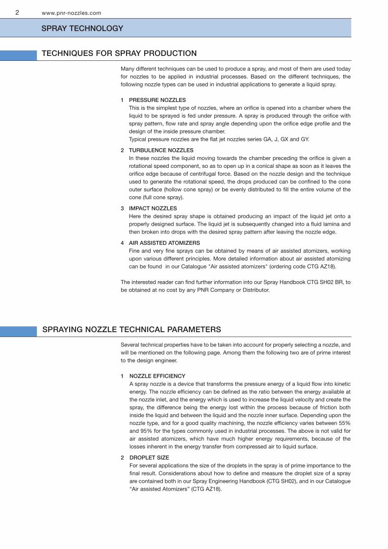
Many different techniques can be used to produce a spray, and most of them are used todayfor nozzles to be applied in industrial processes. Based on the different techniques, thefollowing nozzle types can be used in industrial applications to generate a liquid spray.
1 PRESSURE NOZZLESThis is the simplest type of nozzles, where an orifice is opened into a chamber where theliquid to be sprayed is fed under pressure. A spray is produced through the orifice withspray pattern, flow rate and spray angle depending upon the orifice edge profile and thedesign of the inside pressure chamber.Typical pressure nozzles are the flat jet nozzles series GA, J, GX and GY.
2 TURBULENCE NOZZLESIn these nozzles the liquid moving towards the chamber preceding the orifice is given arotational speed component, so as to open up in a conical shape as soon as it leaves theorifice edge because of centrifugal force. Based on the nozzle design and the techniqueused to generate the rotational speed, the drops produced can be confined to the coneouter surface (hollow cone spray) or be evenly distributed to fill the entire volume of thecone (full cone spray).
3 IMPACT NOZZLESHere the desired spray shape is obtained producing an impact of the liquid jet onto aproperly designed surface. The liquid jet is subsequently changed into a fluid lamina andthen broken into drops with the desired spray pattern after leaving the nozzle edge.
4 AIR ASSISTED ATOMIZERSFine and very fine sprays can be obtained by means of air assisted atomizers, workingupon various different principles. More detailed information about air assisted atomizingcan be found in our Catalogue "Air assisted atomizers" (ordering code CTG AZ18).
The interested reader can find further information into our Spray Handbook CTG SH02 BR, tobe obtained at no cost by any PNR Company or Distributor.
Several technical properties have to be taken into account for properly selecting a nozzle, andwill be mentioned on the following page. Among them the following two are of prime interestto the design engineer.
1 NOZZLE EFFICIENCYA spray nozzle is a device that transforms the pressure energy of a liquid flow into kineticenergy. The nozzle efficiency can be defined as the ratio between the energy available atthe nozzle inlet, and the energy which is used to increase the liquid velocity and create thespray, the difference being the energy lost within the process because of friction bothinside the liquid and between the liquid and the nozzle inner surface. Depending upon thenozzle type, and for a good quality machining, the nozzle efficiency varies between 55%and 95% for the types commonly used in industrial processes. The above is not valid forair assisted atomizers, which have much higher energy requirements, because of thelosses inherent in the energy transfer from compressed air to liquid surface.
2 DROPLET SIZEFor several applications the size of the droplets in the spray is of prime importance to thefinal result. Considerations about how to define and measure the droplet size of a sprayare contained both in our Spray Engineering Handbook (CTG SH02), and in our Catalogue“Air assisted Atomizers” (CTG AZ18).
SPRAY TECHNOLOGY
TECHNIQUES FOR SPRAY PRODUCTION
SPRAYING NOZZLE TECHNICAL PARAMETERS

www.pnr-nozzles.com
SPRAY PATTERNS
FULL CONE PATTERN
3
In a full cone spray the droplets are distributed into a volume which is limited by a cone,having its origin point at the nozzle orifice. Such spray pattern is commonly used in a largevariety of industrial processes, since it is the one which allows to distribute in an even waythe water flow onto a surface: the full cone spray pattern is therefore useful, as a typicalexample, to evenly spray cooling liquid on a still surface. Another typical use is to distributeliquid droplets within a certain volume, like for example evenly distributing water droplets inthe inside volume of a cooling tower.
Because of the wide number of processes performed by means of full cone nozzles theoriginal shape has evolved into a range of specialised types, where the full cone spray pattern,or a pattern similar to a full cone one, is obtained by different techniques.
STANDARD FULL CONE (TURBULENCE NOZZLE)These nozzles use a specially shaped vane placed at the nozzle inlet, to give a rotationalspeed to the fluid flowing through the nozzle.Because of the rotational speed of the fluid, water exiting the nozzle orifice is subjected tocentrifugal force and opens up in the shape of a full cone.The extent of the angle of the cone is a function of both exit speed (created from the inletpressure) and the internal design of the nozzle. It can vary in practice from 15° to 120°.
These nozzles can be also produced as square full cone nozzles, where the square shape ofthe pyramidal spray is obtained by a special design of the outlet orifice.Two important details have to be noted from the system designer when using these typeof nozzles:1 - the spray angle is measured on the side of the square section2 - the square section of the spray rotates within the distance from the nozzle orifice to thetarget area.
SPIRAL FULL CONE (DEFLECTION NOZZLE)This is not properly a full cone, but rather a continuous liquid curtain evolving with the shapeof a spiral inside a conical volume. The disadvantage of a scarcely even distribution iscompensated by an exceptionally good resistance to plugging, which makes this nozzle thebest choice in those applications where safety or system reliability are the prime concern, e.g.fire fighting systems.
MULTIPLE FULL CONE (TURBULENCE NOZZLE, AIR ATOMIZER)This spray pattern is used in two cases, that is:A When a wide spray angle is to be reached with nozzles which inherently can only
produce a narrow one, or in such cases where small size droplets and rather highcapacities are required. Therefore several nozzles are grouped in a cluster withdifferent spray directions: the resulting spray pattern occurs from the additional groupof single nozzle sprays and the droplet size of the spray remains the same as one ofsingle nozzle. It must be noted that a smaller nozzle will normally make smaller dropsas compared to a larger size nozzle of the same type operating under the sameconditions.
B When it is necessary to obtain a wide angle jet using nozzles which inherently delivera limited angle spray. In the case of a wide angle air atomizer, for example, the dropletdistribution is obviously not homogeneous and the result is rather a number of smallangle sprays with different directions, but still the liquid is atomized towards all theparts of the volume to be treated
STANDARD FULL CONE
SPIRAL FULL CONE
MULTIPLE FULL CONE

In a flat jet spray the liquid droplets are sprayed in the shape of a flat liquid layer, with differentthickness according to the principle used to generate the spray. A flat jet spray nozzle servesthe purpose of spraying onto a surface or an object moving in a transverse direction withrespect to the one of the jet surface, a typical example being the nozzles in a car washingtunnel. The vast majority of flat spray nozzles used in the industry work according to one ofthe following principles.
IN LINE FLAT JET (PRESSURE NOZZLE)This is the general purpose flat jet nozzle, where the liquid enters the nozzle in line with theaxis length and is fed to a pressure chamber, from where it is ejected through the nozzleorifice. Flow value and spray angle are determined respectively from the orifice cross sectionand the orifice edge profile.
IN LINE STRAIGHT JET (PRESSURE NOZZLE)These nozzles can be considered a special kind of flat jet nozzle, with naught degree sprayangle. They are designed to produce a sharp stable stream, with powerful impact on a givenpoint, and serve normally to perform cleaning processes or to cut soft materials.
SPOON FLAT JET (DEFLECTION NOZZLE)In this type of nozzle the liquid is fed under pressure to a round outlet orifice, and thendeflected onto a smooth profiled surface so as to assume a flat jet shape. This sophisticateddesign is of advantage since it offers a stronger jet impact using the same feed pressure.Higher efficiency comes from the very little energy required to just change the direction of theliquid flow, this being the only energy required to generate the flat jet.
A hollow cone spray pattern consists of droplets concentrated onto the outer surface of aconical shape volume, with no droplets contained in the inside of the conical jet shape.These nozzles are normally used for smoke washing or gas cooling applications in severalindustrial processes.
HOLLOW CONE (TURBULENCE NOZZLE)These nozzles use a tangential injection of liquid into a whirling chamber to generatecentrifugal forces which break up the liquid vein as soon as it leaves the orifice. Preciselydesigned orifice profiles, making use of the Coanda effect, provides the ability to obtainvery large spray angles.
HOLLOW CONE (DEFLECTION NOZZLE)A hollow cone can also be obtained taking a liquid flow to change direction onto a properlydesigned surface, in order to break the liquid into droplets and distributing them as a hollowcone spray pattern.This kind of nozzle is mainly used for applications in dust control and fire fighting systems.
HOLLOW CONE SPRAY PATTERN
www.pnr-nozzles.com
SPRAY PATTERNS
FLAT JET SPRAY PATTERN
4

www.pnr-nozzles.com 5
NOZZLE IDENTIFICATION CODES
PNR CODING SYSTEM
As any other industrial product, spray nozzles need to be precisely identified by means of a code in order to avoidmistakes.PNR coding system has been designed with the following requirements in mind:- Codes must be easily processed by a computer, in ascending order.- Codes must describe completely the product without any need for additional description.- Codes must show to the user the basic specifications of the nozzle in order to ease the search in the catalogue.We have therefore determined our coding system described as follows:
AA U 2 305 B31 X Y
Nozzle tables report on a blue background thenominal flow value, measured at 3,0 bar.Flow values at different pressures have beencalculated.
Thread type or other connection
Special features
Nozzle material code (see below)
The three digits give the nozzle capacity in lpm at 3 baraccording to rank value
Rank of flow value, see table below
Nozzle spray angle, see table below
Nozzle type, as described in the catalogue pages, shownin ascending order
NOZZLE MATERIAL CODES
These codes serve as an indication only.Based on different types of nozzles, their significancecan occasionally be different.
Capacity rank
Rank Flow digits Actual flow (l/min)
0 0 490 0,491 1 490 4,902 2 490 49,03 3 490 4904 4 490 4900
Some spray angle codes (degrees)
A = 0B = 15C = 20D = 25F = 30H = 35
L = 40M = 45N = 50Q = 60R = 65S = 75
T = 80U = 90J = 110W = 120Y = 130Z = 180
A1 Carbon steel
A2 High speed steel
A8 Zinc coated steel
A9 Nickel coated steel
B1 AISI 303 Stainless steel
B2 AISI 304 Stainless steel
B21 AISI 304 L Stainless steel
B3 AISI 316 Stainless steel
B31 AISI 316 L Stainless steel
C2 AISI 416 Stainless steel, hardened
D1 Polyvinylchloride (PVC)
D2 Polypropylene (PP)
D3 Polyamide (PA)
D5 Talcum filled Polypropylene
D6 Glassfibre reinforced PP
D7 High density polyethilene
D8 Polyvinylidenefluoride (PVDF)
E0 EPDM
E1 Polytetrafluorethylene (PTFE)
E2 PTFE (25% glassfibers)
E31 Acetalic resin (POM)
E7 Viton
E8 Synthetic rubber (NBR)
F5 Ceramic
F31 Ruby insert, 303 body
G1 Cast iron
H1 Titanium
L1 Monel 400
L2 Incolloy 825
L8 Hastelloy C276
P6 Acr. But. Styrene (ABS)
P8 EPDM 40 Shore
T1 Brass
T2 Brass, chrome plated
T3 Copper
T5 Bronze
T8 Brass, nickel plated
T81 Brass, electroless nickel plated
V1 Aluminum
V7 Aluminum, electroless n. plated

www.pnr-nozzles.com6
A wide choice of full cone nozzles are shown on the following pages, covering anypossible requirement for standard industrial processes.The table below list full nozzle type codes, and beside each type are some generalindications about nozzle style, special features, spray pattern and specificapplications, in order to assist your choice.Full cone nozzles are normally delivered in brass or AISI 316 Stainless steel, while awide choice of other materials like PVC, Polypropylene, Teflon, Hastelloy, Titaniumcan be supplied on request.Please note that nozzles shown in this Catalogue are listed for general purposeapplications, additional nozzle types designed specifically for specific applications areshown in other Catalogues as listed on the back cover page and shown at page 55.
FULL CONE NOZZLES RANGE OVERVIEW
6
Type Connection Design Feature Pattern Recommended Page
AA Male thread In line Short body Round Plastic materials 07AE Flange In line Large capacity Round Coke quench 08AL Male/Female In line Non clogging Round General 09AT Male thread Tangential Non clogging Round Demister wash 10BA Female thread In line Three pieces Round Cleanable 11BB Female thread In line Three pieces Square Cleanable 12BC Male thread In line Three pieces Round Cleanable 11BD Male thread In line Three pieces Square Cleanable 12BE Female thread In line Cast body Round General 13BF Female thread In line Cast body Square General 15BG Male thread In line Small capacity Round General 13BH Male thread In line Two pieces Square Surface cooling 15BL Flange In line Large capacity Round General 14BR Female thread In line Narrow spray Round Cleanable 16BS Male thread In line Narrow spray Round Cleanable 16BX Nipple & nut In line Manifold mount Round Continuous casting 17CA Female thread In line Cluster jet Round Cooling 18D Male thread In line Two pieces Round General 20E Male thread In line Non clogging Spiral Scrubbers 24
FULL CONE FULL CONE FULL CONERound spray Cluster spray Square pattern

www.pnr-nozzles.com
FULL CONE NOZZLES
AA
7
SLOTTED VANE
Type AA full cone nozzles are made out of a body and a slotted vane,for even spray distribution.This type of construction offers a nozzle length generally shorter thanother types, and it is used in applications where strict spacerequirements are to be met.Connection thread is parallel, according to BSP standards.Typical applications in gas cooling, washing processes and fire fightingsystems.Their compact design makes them the best choice where a plasticmaterial like PVC, PP or PTFE is required. The robust construction ofthe vane prevents it collapsing when subjected to high temperature,also there is a price advantage resulting from less material beingrequired to provide a nozzle of shorter length.In addition these nozzles can be readily manufactured from almost anymachineable material, making them the best choice when urgentdelivery is requested.
Materials B31 AISI 316L Stainless steelT1 BrassD All plastic materials on request
While AA type nozzles are available on request in several materials, thedifferent sizes are normally stocked or produced in brass, PVC and 316stainless steel according to the Material Table beside. Also, please notethat the wrench sizes given in the above table refer to brass nozzles,while stainless steel and plastic bars may have different sizes.
AA nozzles designis ideally suited forplastic materials.
Slotted disc vane
Code RG D D1 Capacity (lpm) H H1 WSinch mm mm at different pressure values (bar) mm mm mm
0.5 0.7 1.0 2.0 3.0 5.0 7.0 10
90° AAU 2305 xx 3/4 6.1 3.0 12.5 14.7 17.6 24.9 30.5 39.4 46.6 55.7 22 10 32AAU 2385 xx 6.7 3.0 15.7 18.6 22.2 31.4 38.5 49.7 58.8 70.3AAU 2490 xx 7.8 4.0 20.0 23.7 28.3 40.0 49.0 63.3 74.8 89.4AAU 2610 xx 1 9.0 4.0 24.9 29.5 35.2 49.8 61.0 78.7 93.1 111 27 12 40AAU 2780 xx 10.5 5.0 31.9 37.7 45.1 63.7 78.0 101 119 142AAU 3123 xx 1+1/4 12.5 6.0 50.2 59.4 71.0 100 123 158 187 224 30 14 50AAU 3194 xx 1+1/2 16.0 6.0 79.2 93.8 112 158 194 250 296 354 35 16 60AAU 3310 xx 2 20.0 7.0 127 150 179 253 310 400 473 564 45 18 75AAU 3386 xx 23.0 9.0 158 186 223 315 386 498 589 703AAU 3490 xx 2+1/2 25.0 12.0 200 237 283 400 490 632 748 894 52 22 90AAU 3610 xx 28.5 13.0 249 295 352 498 610 787 931 1112AAU 3775 xx 3 32.0 16.0 317 375 448 633 775 1000 1183 1412 60 24 110
120° AAW 2490 xx 3/4 7.9 3.0 20.0 23.7 28.3 40.0 49.0 63.3 74.8 89.4 38 11 32AAW 2780 xx 1 13.7 6.0 31.9 37.7 45.1 63.7 78.0 101 119 142 47 15 40AAW 3123 xx 1+1/4 12.7 6.0 50.2 59.4 71.0 100 123 158 187 224 62 19 50AAW 3194 xx 1+1/2 16.0 6.0 79.2 93.8 112 158 194 250 296 354 77 21 50AAW 3310 xx 2 20.0 10.0 127 150 179 253 310 400 473 564 99 24 60AAW 3386 xx 22.7 10.0 158 186 223 315 386 498 589 703AAW 3490 xx 2+1/2 25.5 12.0 200 237 283 400 490 632 748 894 123 27 75AAW 3610 xx 30 13.0 249 295 352 498 610 787 931 1112AAW 3775 xx 3 32.0 14.0 317 375 448 633 775 1000 1183 1412 150 30 85
RG
H1H
WS
H1
H
WS
RG
H1
H
WS
RG
MATERIAL 3/4’’ 1” 1+1/4” 1+1/2’’ 2” 2+1/2’’ 3”
AISI 316 • • •Brass •PVC • • • • • • •

SLOTTED VANE
AE type nozzles are designed to deliver large and very large capacityvalues, with a carefully designed and machined inside profile, whichoffers uniform spray distribution and perfect performance even withvery low inlet pressure values.The nozzle is made from castings or welded from steel sheet accordingto its size, and has an upper flange, normally Nominal Pressure equalto 16 bar , for connection to the feed line.Typical application for these nozzle is coke quenching and any otherapplication requesting efficient cooling over large surfaces and insideconditioning towers.
Materials A1 Carbon steelB3 AISI 316 Stainless steelG1 Cast iron
Common ApplicationsCoke quenchingCooling
www.pnr-nozzles.com
FULL CONE NOZZLES
AE
8
G
H
FF
Code DN D D1 Capacity (lpm) FF G Hmm mm mm at different pressure values (bar) mm mm mm
0.25 0.35 0.5 0.7 1.0 2.0 3.0 5.0
90° AEU 3940 xx 80 37 12 340 405 442 520 599 788 940 1195 200 160 140AEU 4118 xx 39 14 425 505 568 670 740 987 1180 1480AEU 4147 xx 100 43 13 535 630 700 830 940 1230 1470 1825 220 180 156AEU 4188 xx 125 53 16 680 810 900 1060 1180 1595 1880 2340 250 210 177AEU 4235 xx 56 16 845 1010 1128 1335 1495 1975 2350 2590AEU 4294 xx 150 59 21 1065 1265 1398 1650 1880 2490 2940 3630 285 240 188AEU 4370 xx 66 24 1345 1593 1795 2120 2320 3140 3700 4610AEU 4470 xx 200 72 28 1710 2020 2180 2565 2995 3930 4700 5860 340 295 250AEU 4588 xx 81 32 2135 2530 2760 3300 3635 4940 5880 7310AEU 4741 xx 250 88 39 2650 3185 3590 4245 4690 6150 7410 9120 395 350 291AEU 4941 xx 99 37 3410 4050 4520 5350 5980 7880 9410 11650
120° AEW 3940 xx 80 36 15 340 405 442 520 599 788 940 1195 200 160 140AEW 4118 xx 40.5 14.5 425 505 568 670 740 987 1180 1480AEW 4147 xx 100 43 18.5 535 630 700 830 940 1230 1470 1825 220 180 156AEW 4188 xx 125 53 22 680 810 900 1060 1180 1595 1880 2340 250 210 177AEW 4235 xx 55 24 845 1010 1128 1335 1495 1975 2350 2590AEW 4294 xx 150 59 28 1065 1265 1398 1650 1880 2490 2940 3630 285 240 188AEW 4370 xx 66 32 1345 1593 1795 2120 2320 3140 3700 4610AEW 4470 xx 200 75 35 1710 2020 2180 2565 2995 3930 4700 5860 340 295 250AEW 4588 xx 81 40 2135 2530 2760 3300 3635 4940 5880 7310AEW 4741 xx 250 86 37 2650 3185 3590 4245 4690 6150 7410 9120 395 350 291AEW 4941 xx 96 42 3410 4050 4520 5350 5980 7880 9410 11650

www.pnr-nozzles.com
FULL CONE NOZZLES
AL
9
S-TYPE VANE
AL style nozzles offer distinct advantages due to their specialconstruction, with an integrated S-shape vane cast in one piece withthe nozzle body.Because of their special design they offer the largest free passageavailable in a full cone nozzle (actually identical to the nozzle orificediameter) and can easily handle dirty or recirculated liquids as well asforeign matters.The best reliability is then assured under the most difficult conditions,which makes these nozzles the right choice in those plants with nozzleclogging problems or where removing and cleaning a clogged nozzle isa difficult job.
Materials B31 AISI 316 L Stainless steelOr any castable alloy on request.
AL style nozzles feature a special S-vane design, allowing thenarrowest free passage inside the nozzle to be approximatelyequal to the nozzle orifice diameter.They offer therefore the widest possible passage among all fullcone nozzles working with an internal vane.
Common ApplicationsFire protectionGas scrubbersCoolingWashing gravelDust control
WS
H
RG
ALU ALW Code RG D Capacity (lpm) H WS DIA W90° 120° inch mm at different pressure values (bar) mm mm mm Kg
0.25 0.5 1.0 2.0 3.0 4.0 5.0
• • 2208 xx 3/8 5.82 8.53 11.9 17.1 20.8 23.9 26.8 38 22 0.10• • 2209 xx 1/2 5.82 8.53 11.9 17.1 20.8 23.9 26.8 48 27 0.15• • 2373 xx 10.4 15.3 21.3 30.6 37.3 42.9 48.1• • 2671 xx 3/4 8.7 19.4 27.4 38.7 54.8 67.1 77.5 86.6 60 32 0.20• • 2792 xx 9.5 22.9 32.3 45.7 64.7 79.2 91.5 102• • 2793 xx 1 9.5 22.9 32.3 45.7 64.7 79.2 91.5 102 75 38 0.35• • 2959 xx 10.3 27.5 38.9 55.0 77.7 95.9 110 123• • 3111 xx 11.1 32.0 45.3 64.1 90.6 112 128 143• • 3112 xx 1+1/4 11.1 32.0 45.3 64.1 90.6 112 128 143 86 50 0.60• • 3144 xx 12.7 41.3 58.4 82.6 117 144 165 185• • 3160 xx 13.5 45.9 64.9 91.8 130 160 184 205• • 3175 xx 14.3 50.5 71.4 101 143 176 202 226• • 3176 xx 1+1/2 14.3 50.5 71.4 101 143 176 202 226 86 50 0.60• • 3198 xx 15.1 57.2 80.8 114 162 198 229 256 112 60 0.90• • 3212 xx 15.9 61.2 86.5 122 173 212 245 274• • 3227 xx 16.7 74.2 105 148 210 257 297 332• • 3270 xx 17.5 77.9 110 156 220 270 312 349• • 3328 xx 2 19.0 94.7 134 189 268 328 379 423 160 70 1.6• • 3360 xx 20.6 104 147 208 294 360 416 465• • 3445 xx 22.3 128 182 257 363 445 514 574• • 3499 xx 23.8 144 204 288 407 499 576 644• • 3586 xx 25.4 167 237 335 474 586 671 750• • 3714 xx 28.5 206 291 412 583 714 824 922

VANELESS - OFF LINE
These nozzles can produce a full cone spray pattern withoutany vane inside the whirl-chamber, which has free internalpassages and is therefore less prone to clogging. The sprayaxis has an angle of 90° to the axis of the nozzle feed inlet.The spray consists of coarse drops insensitive to wind drift,well distributed over the spray area and with a stable sprayangle over a wide range of inlet pressure values.
Materials B3 AISI 316 Stainless steelT1 BrassPlastic materials on request
This type of nozzle is often manufactured in small quantities,special materials and customized specifications, and usually notkept available in stock. Please check with our offices for deliverytime about the nozzles you require.
www.pnr-nozzles.com
Common ApplicationsProfile washing in drop eliminatorsRotary filter washing
AccessoriesSwivel jointsLine filters
FULL CONE NOZZLES
AT
10
Code RG D D1 Capacity (lpm) H L WSinch mm mm at different pressure values (bar) mm mm mm
1.0 2.0 3.0 4.0 5.0 6.0 7.0
H WS
L
RG
60° ATQ 1390 xx 1/4 2.4 2.2 2.25 3.18 3.90 4.50 5.03 5.52 5.96 25 34 20ATQ 1740 xx 3.3 3.2 4.27 6.04 7.40 8.54 9.55 10.5 11.3
90° ATU 1230 xx 1/8 2.1 1.8 1.33 1.88 2.30 2.66 2.97 3.25 3.51 22 24 15ATU 1390 xx 1/4 2.5 2.1 2.25 3.18 3.90 4.50 5.03 5.52 5.96 25 34 20ATU 1490 xx 3.0 2.1 2.83 4.00 4.90 5.66 6.33 6.93 7.48ATU 1621 xx 3/8 3.5 3.2 3.58 5.06 6.20 7.16 8.00 8.80 9.50 27 34 20ATU 1740 xx 3.3 3.2 4.27 6.04 7.40 8.54 9.55 10.5 11.3ATU 1780 xx 5.0 3.4 4.50 6.37 7.80 9.00 10.1 11.0 11.9ATU 2110 xx 5.1 4.3 6.35 8.98 11.0 12.7 14.2 15.6 16.8ATU 2153 xx 5.3 5.2 8.80 12.5 15.3 17.7 19.8 21.6 23.4ATU 2196 xx 11.3 16.0 19.6 22.6 25.3 27.7 29.9ATU 2245 xx 1/2 8.7 5.5 14.1 20.0 24.5 28.3 31.6 34.6 37.4 38 48 30ATU 2315 xx 8.7 6.5 18.2 25.7 31.5 36.4 40.7 44.5 48.1ATU 2530 xx 3/4 12.6 8.7 30.6 43.3 53.0 61.2 68.4 75.0 81.0 50 58 40ATU 2770 xx 12.6 11.2 44.5 62.9 77.0 88.9 99.4 109 118ATU 2420 xx 1 9.2 9.8 24.2 34.3 42.0 48.5 54.2 59.4 64.2 48 61 42ATU 2645 xx 10.3 10.3 37.2 52.7 64.5 74.5 83.3 91.2 98.5
120° ATW 1310 xx 1/8 2.5 2.1 1.82 2.48 3.10 3.58 4.02 4.40 4.65 22 24 15ATW 1311 xx 1/4 2.5 2.1 1.82 2.48 3.10 3.58 4.02 4.40 4.65 25 34 20 ATW 1490 xx 4.1 2.4 2.83 4.00 4.90 5.66 6.33 6.93 7.48ATW 1780 xx 3/8 5.0 3.4 4.50 6.37 7.80 9.00 10.1 11.0 11.9 27 34 20ATW 2110 xx 5.4 4.4 6.35 8.98 11.0 12.7 14.2 15.6 16.8ATW 2153 xx 5.3 5.2 8.80 12.5 15.3 17.7 19.8 21.6 23.4ATW 2196 xx 11.3 16.0 19.6 22.6 25.3 27.7 29.9ATW 2245 xx 1/2 8.5 5.5 14.1 20.0 24.5 28.3 31.6 34.6 37.4 38 48 30ATW 2315 xx 8.5 6.3 18.2 25.7 31.5 36.4 40.7 44.5 48.1ATW 2480 xx 3/4 12.6 7.8 27.7 39.2 48.0 55.4 62.0 67.9 73.3 56 59 40ATW 2770 xx 14.0 10.7 44.5 62.9 77.0 88.9 99.4 109 118ATW 2420 xx 1 9.5 8.0 24.2 34.3 42.0 48.5 54.2 59.4 64.2 48 61 42ATW 2645 xx 12.8 9.2 37.2 52.7 64.5 74.5 83.3 91.2 98.5 58 61 40ATW 2870 xx 16.0 11.5 50.2 71.0 87.0 100 112 123 133 61 68 45ATW 3122 xx 18.0 14.0 70.4 99.6 122 141 157 175 186 66 76 50

www.pnr-nozzles.com
FULL CONE NOZZLES
BA/BC
11
X-VANE / ROUND SPRAY / THREE PIECES
These full cone nozzles offer a three-piece design based on the clogresistant X-vane design plus the convenience of an easy and fast internalcleaning since they can be easily disassembled for maintenance. Thenipple design avoids loosing the vane when the nozzle is mountedspraying upwards. Available with female (BA) or male (BC) inlet threadnipple, see dimensions and weights at the bottom the page.
Materials B1 AISI 303 Stainless steelB3 AISI 316 Stainless steel on requestT1 Brass
BA
BC
Standard spray
BAQ BCQ Code RF D D1 Capacity (lpm) Spray angle (degrees)RG at different pressure values (bar) at pressure (bar)
inch mm mm 0.7 1.0 2.0 3.0 5.0 7.0 10 0.7 1.5 5.0
Wide spray
BAW BCW Code RF/RG D D1 0.7 1.0 2.0 3.0 5.0 7.0 10 0.7 1.5 5.0
Nozzle RF/RG H WS WType inch mm mm kg
1/8 30 14 0.031/4 37 17 0.04BA/BB3/8 46 19 0.071/2 57 25 0.20
Nozzle RF/RG H WS WType inch mm mm kg
1/8 32 14 0.021/4 39 17 0.04BC/BD3/8 47 19 0.071/2 57 25 0.20
Dimensions and weights
• • 0740 1/8 1.0 0.5 0.36 0.43 0.60 0.74 0.93 1.13 1.35 -- 58 53• • 1110 1.2 0.5 0.53 0.64 0.90 1.10 1.42 1.68 2.01 51 65 60• • 1150 1.4 1.0 0.72 0.87 1.22 1.50 1.94 2.29 2.74 43 59 46• • 1220 1.6 1.0 1.06 1.27 1.80 2.20 2.84 3.36 4.02 50 65 60• • 1260 1.6 1.3 1.26 1.50 2.12 2.60 3.36 3.97 4.75 43 48 45• • 1370 2.0 1.3 1.79 2.14 3.02 3.70 4.78 5.70 6.76 50 65 58• • 1480 1/4 2.4 1.7 2.32 2.77 3.92 4.80 6.20 7.30 8.76 45 50 45• • 1740 2.9 1.7 3.57 4.27 6.04 7.40 9.60 11.3 13.5 55 65 60• • 1930 3.2 1.7 4.46 5.34 7.61 9.30 12.0 14.2 16.9 68 70 67• • 1700 3/8 3.0 2.0 3.38 4.04 5.71 7.00 9.03 10.7 12.7 45 50 45• • 2111 3.4 2.4 5.36 6.40 9.10 11.1 14.3 17.0 20.3 65 68 60• • 2163 4.5 2.4 7.87 9.40 13.3 16.3 21.0 24.9 29.8 85 90 80• • 2118 1/2 3.4 3.0 5.70 6.80 9.60 11.8 15.2 18.0 21.5 50 50 45• • 2185 4.4 3.0 8.94 10.7 15.1 18.5 23.9 28.3 33.8 65 68 60• • 2240 5.0 3.0 11.6 13.9 19.6 24.0 31.0 36.7 43.8 70 75 65• • 2300 5.6 3.0 14.5 17.3 24.5 30.0 38.7 45.8 54.8 90 92 85
• • 1200 1/8 1.5 1.0 0.97 1.15 1.63 2.00 2.58 3.06 3.65 120 115 104• • 1310 1.8 1.0 1.50 1.79 2.53 3.10 4.00 4.74 5.66 120 110 104• • 1400 2.3 1.0 1.93 2.31 3.27 4.00 5.16 6.11 7.30 120 110 104• • 1570 2.5 1.1 2.75 3.29 4.65 5.70 7.36 8.71 10.4 120 110 104• • 1720 1/4 3.3 1.7 3.48 4.16 5.88 7.20 9.30 11.0 13.1 120 110 105• • 1860 3.4 1.3 4.15 4.97 7.02 8.60 11.1 13.1 15.7 120 110 105• • 2100 3.6 1.6 4.83 5.77 8.16 10.0 12.9 15.3 18.3 120 110 105• • 2122 3/8 3.9 1.6 5.89 7.04 9.96 12.2 15.8 18.6 22.3 120 110 105• • 2144 4.3 2.4 6.96 8.30 11.8 14.4 18.6 22.0 26.3 120 110 105• • 2172 4.9 2.4 8.31 9.90 14.0 17.2 22.2 26.3 31.4 120 110 105• • 2194 5.3 2.5 9.37 11.2 15.8 19.4 25.0 29.6 35.4 120 110 105• • 2220 1/2 5.0 3.0 10.6 12.7 18.0 22.0 28.4 33.6 40.2 120 115 110• • 2250 5.3 3.0 12.1 14.4 20.4 25.0 32.3 38.2 45.6 120 115 110• • 2290 5.6 3.0 14.0 16.7 23.7 29.0 37.4 44.3 52.9 120 115 110• • 2320 6.7 3.5 15.5 18.5 26.1 32.0 41.3 48.9 58.4 120 115 110• • 2360 7.6 4.0 17.4 20.8 29.4 36.0 46.5 55.0 65.7 120 115 110
RG
WSH
H
WS
BA
BC
RF

www.pnr-nozzles.com
X-VANE / SQUARE SPRAY / THREE PIECES
Same three-piece nozzle can also be manufactured to supply a squaresection spray pattern, to optimize their performance where the coverage ofa surface is required to be as even as possible. Please note that the sides ofthe square spray section are not in line with the grooves on the nozzleorifice, the offset angle being between 10° and 15° depending upon workingpressure and distance. The proper alignement of the nozzles should beobtained at the time when the system is installed or serviced.
Materials B1 AISI 303 Stainless steelB3 AISI 316 Stainless steel on requestT1 Brass
FULL CONE NOZZLES
BB/BD
12
Common Applications Drop production in chemical reactorsScrubbing and washing with recirculated liquidsWashing and rinsing processes
AccessoriesAssembly clamps for feed pipesSwivel jointsStrainersOne way valves
Dimensions and weights
BB
BD
Square spray
BBQ BDQ Code RF D D1 Capacity (lpm) Spray angle (degrees)RG at different pressure values (bar) at pressure (bar)
inch mm mm 0.7 1.0 2.0 3.0 5.0 7.0 10 0.7 1.5 5.0
• • 1270 1/8 1.8 1.0 1.30 1.56 2.20 2.70 3.49 4.12 4.93 42 55 48• • 1360 1.9 1.3 1.74 2.08 2.94 3.60 4.65 5.50 6.57 48 60 60• • 1440 2.1 1.3 2.13 2.54 3.59 4.40 5.68 6.72 8.03 60 65 60• • 1740 1/4 2.8 1.6 3.57 4.27 6.04 7.40 9.55 11.3 13.5 60 65 60• • 1890 3.2 1.6 4.30 5.14 7.27 8.90 11.5 13.6 16.2 65 67 60• • 2110 3.8 1.6 5.31 6.35 8.98 11.0 14.2 16.8 20.1 75 80 75• • 2133 3/8 3.8 2.4 6.42 7.68 10.9 13.3 17.2 20.3 24.3 70 72 65• • 2210 1/2 5.6 3.0 10.1 12.1 17.2 21.0 27.1 32.1 38.3 70 74 65• • 2270 6.4 3.2 13.0 15.6 22.0 27.0 34.9 41.2 49.3 75 80 75
Nozzle RF/RG H WS WType inch mm mm kg
1/8 30 14 0.031/4 37 17 0.04BA/BB3/8 46 19 0.071/2 57 25 0.20
Nozzle RF/RG H WS WType inch mm mm kg
1/8 32 14 0.021/4 39 17 0.04BC/BD3/8 47 19 0.071/2 57 25 0.20
WS
H
BB
RF
WS
H
BD
RG

www.pnr-nozzles.com
FULL CONE NOZZLES
13
BE/BG X-VANE/ROUND SPRAY/TWO PIECES
These full cone nozzles have a two-piece design and produce a full cone round spray, with anglesranging between 70° and 120° and capacities between 4.8 and 1040 litres per minute. Highercapacities, up to 11,300 lpm can be obtained with the larger sizes shown in the following table.The X-vane design assures a satisfactory compromise as far as even coverage of the spray and nozzleresistance to clogging are considered, and is therefore a widely popular choice. The table on this pageshows female threaded nozzles up to 3” size, larger capacity nozzles both with female threads andflange connections are shown on the next page. Please note BE nozzles have a female BSP thread,BG have a male BSPT thread. Dimensions for standard and wide spray angle nozzles are shown onthe table at the bottom of this page.
Materials B1 AISI 303 Stainless steelB31 AISI 316L Stainless steelT1 Brass, only sizes 1” and smaller
Standard spray angles
BG
BE
BES BGQ Code RF D D1 Capacity (lpm) Spray angle (degrees)RG at different pressure values (bar) at pressure (bar)
inch mm mm 0.5 1.0 2.0 3.0 5.0 7.0 10 0.7 3.0 5.0
WS
H
RG
DIA
H
RF
RF
WSH
BE
BE
BG
• 1480 xx 1/4 2.3 1.6 1.96 2.77 3.92 4.80 6.20 7.33 8.76 55 60 55• 1740 xx 2.9 1.6 3.02 4.27 6.04 7.40 9.55 11.3 13.5 65 62 62• 1700 xx 3/8 2.6 2.4 2.86 4.04 5.72 7.00 9.04 10.7 12.8 66 60 55• 2111 xx 3.6 2.4 4.53 6.41 9.06 11.0 14.3 17.0 20.3 65 67 60• 2163 xx 4.5 2.8 6.65 9.41 13.3 16.3 21.0 24.9 29.8 59 62 60• 2185 xx 1/2 4.6 3.2 7.55 10.7 15.1 18.5 23.9 28.3 33.8 64 65 60• 2300 xx 6.3 3.6 12.2 17.3 24.5 30.0 38.7 45.8 54.8 58 60 58
• • 2220 xx 3/4 4.9 4.4 9.00 12.7 18.0 22.0 28.4 33.6 40.2 54 60 56• • 2350 xx 6.4 4.4 14.3 20.2 28.6 35.0 45.2 53.5 63.9 56 63 60• • 2610 xx 9.5 5.2 24.9 35.2 49.8 61.0 78.8 93.2 111 58 65 60• • 2370 xx 1 6.0 5.6 15.1 21.4 30.2 37.0 47.8 56.5 67.6 58 60 56• • 2611 xx 8.3 5.6 24.9 35.2 49.8 61.0 78.8 93.2 111 60 61 58• • 2870 xx 11.9 5.6 35.5 50.2 71.0 87.0 112 133 60 63 60• • 3104 xx 11.9 6.4 42.5 60.0 84.9 104 134 159 62 65 61• 2520 xx 1+1/4 7.4 6.4 21.2 30.0 42.5 52.0 67.1 79.4 72 75 65• 2871 xx 9.6 6.4 35.5 50.2 71.0 87.0 112 133 72 75 68• 3105 xx 10.7 6.4 42.9 60.6 85.7 105 136 160 72 75 70• 3122 xx 12.3 6.4 49.8 70.4 99.6 122 158 186 72 75 71• 3174 xx 15.1 7.9 71.0 100 142 174 225 266 74 75 71• 2872 xx 1+1/2 9.5 8.7 35.5 50.2 71.0 87.0 112 133 68 72 65• 3139 xx 12.7 8.7 56.7 80.3 113 139 179 212 68 72 70• 3175 xx 14.3 8.7 71.4 101 143 175 226 267 72 75 70• 3260 xx 18.3 10.3 106 150 212 260 336 397 74 78 73• 3148 xx 2 12.7 11.1 60.4 85.4 121 148 191 226 68 70 68• 3261 xx 17.3 11.1 106 150 212 260 336 397 70 73 68• 3305 xx 19.2 11.1 125 176 249 305 394 466 72 75 70• 3350 xx 21.0 11.1 143 202 286 350 452 535 72 75 70• 3435 xx 23.8 14.3 178 251 355 435 562 664 71 75 72• 3520 xx 28.6 14.3 212 300 425 520 671 794 74 77 72• 3215 xx 2+1/2 15.1 14.3 87.8 124 176 215 278 328 70 73 70• 3436 xx 22.2 14.3 178 251 355 435 562 664 72 75 70• 3521 xx 24.6 14.3 212 300 425 520 671 794 72 75 70• 3610 xx 28.6 14.3 249 352 498 610 788 932 73 75 70• 3700 xx 28.6 17.5 286 404 572 700 904 1069 73 77 72• 3780 xx 31.8 17.5 318 450 637 780 1007 1191 75 78 75• 3365 xx 3 19.1 17.5 149 211 298 365 471 558 70 73 68• 3701 xx 27.8 17.5 286 404 572 700 904 1069 70 73 70• 3781 xx 30.2 17.5 318 450 637 780 1007 1191 72 75 70• 3870 xx 32.5 17.5 355 502 710 870 1123 1329 72 75 70• 4104 xx 34.9 20.6 425 600 849 1040 1343 1589 75 78 73
Dimensions
Size inch 1/8 1/4 3/8 1/2 3/4 1 1+1/4 1+1/2 2 2+1/2 3BG H mm 19.5 22.0 25.0 33.0 40.0 51.5
WS mm 12.0 14.0 17.0 22.0 22.0 27.0H mm 55.5 68.0 90.0 105 140 180 192
BE DIA mm 32.0 38.0WS mm 27.0 32.0 48.0 52.0 67.0 85.0 100

BE/BL
www.pnr-nozzles.com14
FULL CONE NOZZLES
X-VANE/LARGE CAPACITIES
The large capacity nozzles feature a full cone spray pattern with uniformdistribution over a round impact area, for applications where a very largecapacity is required (values up to 11.300 litres per minute). They aremanufactured with large spray angles, while still assuring high waterdensity per square meter. The bodies are machined from a casting, andcan be finished either with a female thread connection (BE type) or withan integral ANSI flange (BL type).
Materials B31 AISI 316L Stainless steelG1 Cast iron
BE/BG
BE
H 2WSH
RF DF
BE BL
Large capacity
BEU BLU Code RF D D1 Capacity (lpm) DimensionDF at different pressure values (bar) mm
inch mm mm 0.7 1.0 2.0 3.0 5.0 7.0 10 H H2 WS
• • 4139 xx 4 43 19 671 803 1135 1390 1794 2123 2538 251 207 130• • 4157 xx 47 22 758 906 1282 1570 2027 2398 2866• • 4174 xx 51 25 840 1005 1421 1740 2246 2658 3177• • 4183 xx 54 25 884 1057 1494 1830 2363 2795 3341• • 4218 xx 5 48 29 1053 1259 1780 2180 2814 3330 3980 311 269 170• • 4244 xx 53 29 1179 1409 1992 2440 3150 3727 4455• • 4279 xx 68 35 1348 1611 2278 2790 3602 4262 5094• • 4287 xx 73 35 1386 1657 2343 2870 3705 4384 5240• • 4305 xx 6 61 41 1473 1761 2490 3050 3938 4659 5569 366 321 200• • 4348 xx 70 41 1681 2009 2841 3480 4493 5316 6354• • 4392 xx 77 44 1894 2263 3201 3920 5061 5988 7157• • 4418 xx 82 44 2019 2413 3413 4180 5396 6385 7632• • 4435 xx 8 70 48 2101 2511 3552 4350 5616 6645 7942 470 423 240• • 4520 xx 80 47 2512 3002 4246 5200 6713 7943 9494• • 4610 xx 91 47 2947 3522 4981 6100 7875 9318 11137• • 4694 xx 102 57 3352 4007 5666 6940 8960 10601 12671• • 4785 xx 124 57 3792 4532 6409 7850 10134 11991 14332
• 4695 xx 10 102 57 3357 4013 5675 6950 8972 10616 12689 527• 4870 xx 102 64 4202 5023 7104 8700 11232 13289 15884• 5104 xx 122 67 5024 6004 8492 10400 13426 15886 18988• 5113 xx 135 67 5458 6524 9226 11300 14588 17261 20631
90°
BEW Code RF D D1 Capacity (lpm) at pressure (bar) Dimension mm
DF 0.7 1.0 2.0 3.0 5.0 7.0 10 H H2 WS
120° • 4158 xx 4 47 22 758 906 1282 1570 2027 2398 2538 251 207 130
Wide spray anglesX-VANE/ROUND SPRAY/TWO PIECES
BEW BGW Code RF D D1 Capacity (lpm) Spray angle (degrees) DimensionRG at different pressure values (bar) at pressure (bar) mm
inch mm mm 0.5 1.0 2.0 3.0 5.0 7.0 10 0.7 3.0 5.0 H DIA WS
• 2100 xx 1/4 3.3 1.6 4.08 5.77 8.16 10.0 12.9 15.3 18.3 115 120 106 23 14• 2122 xx 3/8 3.6 2.4 4.98 7.04 9.96 12.2 15.7 18.6 22.3 115 120 105 30 17• 2144 xx 4.0 2.4 5.88 8.31 11.8 14.4 18.6 22.0 26.3 115 120 105• 2172 xx 5.1 2.4 7.02 9.93 14.0 17.2 22.2 26.3 31.4 115 120 105• 2194 xx 5.2 2.8 7.92 11.2 15.8 19.4 25.0 29.6 35.4 115 120 105• 2220 xx 1/2 5.0 3.0 8.98 12.7 18.0 22.0 28.4 33.6 40.2 115 120 105 39 22• 2250 xx 5.4 3.0 10.2 14.4 20.4 25.0 32.3 38.2 45.6 115 120 105• 2290 xx 6.4 3.0 11.8 16.7 23.7 29.0 37.4 44.3 52.9 115 120 105• 2320 xx 6.9 3.0 13.1 18.5 26.1 32.0 41.3 48.9 58.4 115 120 105• 2360 xx 7.6 3.0 14.7 20.8 29.4 36.0 46.5 55.0 65.7 115 120 110
• • 2500 xx 3/4 8.7 4.5 20.4 28.9 40.8 50.0 64.5 76.4 91.3 105 110 105 40 27• • 2920 xx 1 11.5 5.6 37.6 53.1 75.1 92.0 119. 141 105 110 105 54 34• • 3134 xx 1+1/4 14.0 6.0 54.7 77.4 109 134 173 205 110 115 110 88 48• • 3200 xx 1+1/2 16.5 9.0 81.6 115 163 200 258 306 110 115 110 102 52• 3395 xx 2 24.0 11.1 161 228 323 395 510 603 110 115 110 138 67• 3590 xx 2+1/2 26.0 14.3 241 341 482 590 762 901 110 115 110 162 85• 3800 xx 3 32.0 17.5 327 462 653 800 1033 1222 110 115 110 187 100

www.pnr-nozzles.com
FULL CONE NOZZLES
BF/BH
15
X-VANE/SQUARE SPRAY/TWO PIECES
A simpler two piece design is used for BF and BH type nozzles producing a square section spray pattern.Depending upon their size these nozzles are manufactured out of bar stock or casting, drawings,dimensions and weights as shown.They are the convenient choice where the coverage of a surface is required to be as even as possible.Please note that the sides of the square spray section are not in line with the grooves on the nozzle orifice,the offset angle is between 10° and 15° depending upon working pressure and distance.The proper alignment of the nozzles should be obtained at the time when the system is installed orserviced.
Materials B1 AISI 303 Stainless steelB31 AISI 316L Stainless stelT1 Brass
BH
BF
Dimensions and weightsValues are based on thelargest/heaviest nozzle foreach single size.
Standard spray angle
RG
DIA
H
BFS BHQ Code RF D D1 Capacity (lpm) Spray angle (degrees)RG at different pressure values (bar) at pressure (bar)
inch mm mm 0.7 1.0 2.0 3.0 5.0 7.0 10 0.7 3.0 5.0
RG
WS
H
WS
H
RG
RF
H
DIA
WSH
RF
WS
RF
H
• 1270 1/8 1.7 1.3 1.30 1.56 2.20 2.70 3.49 4.12 4.93 52 60 58 • 1350 1.9 1.3 1.74 2.08 2.94 3.60 4.65 5.50 6.57 58 60 60• 1440 2.2 1.3 2.13 2.54 3.59 4.40 5.68 6.72 8.03 60 65 60• 1740 1/4 2.8 1.6 3.57 4.27 6.04 7.40 9.55 11.3 13.5 62 65 60• 1890 3.2 1.6 4.30 5.14 7.27 8.90 11.5 13.6 16.2 62 65 60• 2107 3.8 1.6 5.17 6.18 8.74 10.7 13.8 16.3 19.5 65 65 60• 2133 3/8 4.0 2.4 6.42 7.68 10.9 13.3 17.2 20.3 24.3 60 62 60• 2210 1/2 5.5 3.2 10.1 12.1 17.2 21.0 27.1 32.1 38.3 62 64 60• 2270 6.4 3.2 13.0 15.6 22.0 27.0 34.8 41.2 49.2 62 65 60• 2370 3/4 6.7 4.4 17.8 22.0 31.0 37.0 47.8 56.5 67.5 60 64 62
• 2780 1 1.9 1.3 37.7 45.2 64.3 78.0 101 120 142 77 78 75• 3131 1+1/4 2.4 1.3 63.3 75.6 107 131 169 200 239 77 78 73• 3170 1+1/2 2.8 1.6 82.1 98.1 139 170 219 260 310 75 78 70• 3215 2 3.2 1.6 104 124 176 215 278 328 392 65 72 68• 3265 3.8 1.6 128 153 216 265 342 405 484 73 75 68• 3355 1.6 1.3 171 205 290 355 458 542 648 73 75 70• 3360 2+1/2 1.9 1.3 174 208 294 360 465 550 657 64 70 63• 3435 2.4 1.3 210 251 355 435 562 664 794 75 80 73• 3700 2.8 1.6 338 404 571 700 904 1069 1278 73 76 74• 4220 5 1.9 1.3 1063 1270 1796 2200 2840 3361 4017 73 75 72• 4420 6 2.4 1.3 2029 2425 3429 4200 5422 6416 7668 75 78 74
• 2100 1/4 3.2 1.6 4.83 5.77 8.16 10.0 12.9 15.3 18.3 106 115 100• 2122 3/8 3.9 1.6 5.89 7.04 9.96 12.2 15.8 18.6 22.3 105 120 110• 2144 4.0 2.4 6.96 8.31 11.8 14.4 18.6 22.0 26.3 105 120 110• 2172 4.6 2.4 8.31 9.93 14.0 17.2 22.2 26.3 31.4 105 120 105• 2194 5.4 2.4 9.37 11.2 15.8 19.4 25.0 29.6 35.4 105 120 106• 2220 1/2 4.8 3.0 10.6 12.7 18.0 22.0 28.4 33.6 40.2 105 110 105• 2250 5.1 3.0 12.1 14.4 20.4 25.0 32.3 38.2 45.6 105 110 105• 2290 5.7 3.0 14.0 16.7 23.7 29.0 37.4 44.3 53.0 105 110 105• 2320 7.0 3.0 15.4 18.5 26.1 32.0 41.3 48.9 58.4 105 110 105• 2360 8.0 3.0 17.4 20.8 29.4 36.0 46.5 55.0 65.7 105 110 105
• • 2500 3/4 8.5 4.5 24.2 28.9 40.8 50.0 64.5 76.4 91.3 105 115 103• • 2930 1 11.6 5.6 44.9 53.7 75.9 93.0 120 142 170 107 110 106• 3134 1+1/4 14.5 6.0 64.7 77.4 109 134 173 205 245 108 110 107• 3200 1+1/2 18.2 9.0 96.6 115 163 200 258 305 365 108 115 108• 3395 2 24.0 11.1 191 228 322 395 510 603 721 110 112 108• 3590 2+1/2 26.0 14.3 285 341 482 590 761 901 1077 110 115 110• 3800 3 31.5 17.5 386 462 653 800 1032 1220 1460 110 120 110
BFW BHW Code RF D D1 0.7 1.0 2.0 3.0 5.0 7.0 10 0.7 3.0 5.0RG
Size inch 1/8 1/4 3/8 1/2 3/4 1 1+1/4 1+1/2 2 2+1/2 3 5 6H mm 22 23 30 39 55 70 88 102 138 175 187 311 366WS mm 12 14 17 21 27 32 40 50 60 85 100 170 200DIA mm 32 38W kg 0.01 0.02 0.03 0.04 0.20 0.35 0.55 0.80 1.6 2.0 7.8 18 25
Wide spray angle

www.pnr-nozzles.com16
FULL CONE NOZZLES
BR/BUX-VANE/NARROW SPRAY ANGLES
These nozzles produce a solid cone spray with round spray pattern,where coarse water drops are concentrated within a narrow sprayangle to maximise their impact force per square surface unit.Spray angle values of 15° or 30° are available, with a choice of male orfemale thread connection.The BR and BS nozzle types are manufactured in three pieces, to allowfor easy disassembly and cleaning of the nozzles in case of clogging.
Materials B1 AISI 303 Stainless steel B3 AISI 316 Stainless steel on requestT1 Brass
Spray angle 15°
Spray angle 30°
BT BR BS
• • 1270 xx 1/8 1.6 1.56 2.20 2.70 3.50 4.90 33 35 12• • 1550 xx 2.3 3.18 4.49 5.50 7.10 10.0• • 2117 xx 1/4 3.2 6.75 9.60 11.7 15.1 21.4 44 44 17• • 2196 xx 3/8 4.2 11.3 16.0 19.6 25.3 35.8 53 53 22• • 2352 xx 1/2 5.6 20.3 28.7 35.2 45.4 64.3 72 72 24
• 2587 xx 3/4 7.8 33.9 47.9 58.7 75.8 107 32 72 25• 3110 xx 1 10.2 63.5 89.8 110 142 201 40 92 35• 3168 xx 1+1/4 12.6 97.0 137 168 217 307 48 117 40• 3245 xx 1+1/2 15.1 141 200 245 316 447 60 127 52• 3450 xx 2 22.0 260 367 450 581 822 80 183 70• 3680 xx 2+1/2 26.0 393 555 680 878 1242 90 223 85• 3980 xx 3 31.0 566 800 980 1265 1789 105 268 100
BRB BSB BUB Code RF D Capacity (lpm) DimensionsRG at pressure (bar) mm
inch mm 1.0 2.0 3.0 5.0 10 DIA H1 H2 WS
• • 0980 xx 1/8 1.0 0.57 0.80 0.98 1.27 1.79 33 35 12• • 1160 xx 1.2 0.92 1.31 1.60 2.07 2.92• • 1270 xx 1.6 1.56 2.20 2.70 3.49 4.93• • 1350 xx 1/4 1.8 2.02 2.86 3.50 4.52 6.39 44 44 17• • 1550 xx 3/8 2.3 3.18 4.49 5.50 7.10 10.0 53 53 22• • 2117 xx 1/2 3.2 6.75 9.55 11.7 15.1 21.4 72 72 24• • 2195 xx 3/4 4.2 11.3 15.9 19.5 25.0 36.0 84 87 25
• 2270 xx 1 5.1 15.6 22.0 27.0 35.0 49.0 34 92 35• 2390 xx 6.1 23.0 32.0 39.0 50.0 71.0• 2590 xx 1+1/4 7.4 34.0 48.0 59.0 76.0 108 42 117 40• 2780 xx 8.6 45.0 64.0 78.0 101 142• 2980 xx 1+1/2 9.6 57.0 80.0 98.0 127 179 48 127 52• 3117 xx 10.5 68.0 96.0 117 151 214• 3137 xx 2 11.1 79.0 112 137 177 250 60 200 55• 3156 xx 11.9 90.0 127 156 201 285• 3195 xx 13.5 113 159 195 252 356• 3235 xx 2+1/2 14.7 136 192 235 303 429 70 254 60• 3275 xx 15.9 159 224 275 355 502• 3390 xx 19.1 225 318 390 503 712• 3430 xx 19.8 248 351 430 555 785• 3470 xx 20.6 271 384 470 606 857
BRF BSF BTF Code RF D Capacity (lpm) DimensionsRG at pressure (bar) mm
inch mm 1.0 2.0 3.0 5.0 10 DIA H1 H2 WS
H1
RF
WS
H2
RG
RF
DIA
H1
DIA
H2
RG
WS
BS
BR
BT
BU
Common Applications Washing and cooling inside pipeswashing of productsAgitating liquids inside tanks and vats.

www.pnr-nozzles.com
FULL CONE NOZZLES
BX
BJ
17
NOZZLE TIPS
Full cone tips produce a uniform full cone shaped spray with a roundimpact area.Complete nozzles made out of nozzle tip, seal, nipple and retaining nut.This design allows the nozzle to be disassembled and readily cleanedin case of clogging, for fast and easy maintenance.In addition to metal nipples a range of pipe clamps is available, pleasesee our Accessories Catalogue CTG AC20.
Materials B1 AISI 303 Stainless steelT1 Brass
Under certain conditions, for example nozzle working upside-down at high temperature or subjected to sudden vacuum inpipes, the nozzle vane can escape from the body and impair thenozzle operation.As an added safety feature our full cone nozzles with X-vane, upto the 3/8” thread size, have the vane safely secured in places.
THREADED NOZZLES
Most sizes in the BX range can be obtained as a two-piece nozzle,with a 3/8” female thread.Capacity and spray angle maintain exactly the same values, nozzleidentification code is BJQ.This is convenient where a damaged nipple does not allow for a tightassembly, and avoids the need for disassembling the pipe and replacethe defective nipple, while keeping approximately the same distancebetween the nozzle orifice and the spray target.As an example, the nozzle with the same specifications of the BXQ1372 T1 tip has the code BJQ 1372 T1.
Assembly accessoriesBX tips are normally secured with aretaining nut onto a welded nipple.All details on accessories are shown inour Catalogue CTG AC20.
ZAA 1738 xx VAA 0038 xx
BX11491372
BX15081743
12,2
16
12,2
15
15
21,5
5
60° BXQ 1149 xx 1.3 0.86 1.22 1.49 1.92 2.72 50 50 45BXQ 1223 xx 1.7 1.35 1.90 2.33 3.01 4.25 65 65 49BXQ 1262 xx 1.7 1.51 2.14 2.62 3.38 4.78 50 50 46BXQ 1372 xx 2.1 2.15 3.04 3.72 4.80 6.79 65 65 59BXQ 1508 xx 2.4 2.93 4.15 5.08 6.56 9.30 50 50 46BXQ 1626 xx 2.9 3.61 5.11 6.26 8.08 11.4 60 60 55BXQ 1743 xx 2.9 4.29 6.07 7.43 10.0 14.0 67 67 61
Code D Capacity (lpm)) Spray anglemm at pressure (bar) at different pressure
1.0 2.0 3.0 5.0 10 1.5 3.0 5.0
3/8”WS 22
27

www.pnr-nozzles.com18
FULL CONE NOZZLES
CASCLUSTER NOZZLE/STANDARD SPRAY
CAS multiple full cone nozzles can produce very fine droplets usingonly hydraulic pressure.Their full cone spray pattern results from the interaction of severalhollow cone sprays, whose number (NR) is stated in the capacity tablebelow.Since the droplet size depends among other factors upon the nozzlesize, these multi-orifice nozzles produce a finer spray than a standardfull cone single-orifice nozzle working at the same pressure anddelivering the same quantity of liquid.
Materials B3 AISI 316 Stainless steel on requestT1 Brass
DIA
RF
H
* Double capacity insert
70° CAS 1153 xx 1/2 0.9 0.5 1.08 1.25 1.53 1.98 2.79 7 50 33.5CAS 1274 xx 1.8 0.5 1.94 2.24 2.74 3.54 5.00CAS 1343 xx 3/4 1.1 1.0 1.66 1.98 2.43 2.80 3.43 4.43 6.26 7 72 43CAS 1551 xx 1.5 1.4 2.66 3.18 3.90 4.50 5.51 7.11 10.1 CAS 1870 xx 2.1 2.0 4.20 5.02 6.15 7.10 8.70 11.2 15.9CAS 2116 xx 2.5 2.0 5.60 6.70 8.20 9.47 11.6 15.0 21.2CAS 2145 xx 3.0 2.0 7.00 8.37 10.2 11.8 14.5 18.7 26.5CAS 2184 xx 3.5 2.0 8.89 10.6 13.0 15.0 18.4 23.8 33.6CAS 2220 xx 4.0 2.0 10.6 12.7 15.6 18.0 22.0 28.4 40.2 CAS 2342 xx 3.5 *2.0 16.5 19.8 24.3 28.0 34.3 44.3 62.6CAS 2434 xx 4.0 *2.0 21.0 25.1 30.7 35.4 43.4 56.0 79.2CAS 2551 xx 5.0 *2.0 26.6 31.8 39.0 45.0 55.1 71.1 101CAS 2728 xx 6.0 *2.0 35.2 42.0 51.5 59.4 72.8 94.0 133CAS 2385 xx 1 5.0 2.5 18.5 22.2 27.2 31.4 38.5 49.7 70.3 7 140 74CAS 2489 xx 6.5 2.5 23.6 28.2 34.5 39.9 48.9 63.1 89.2 CAS 2685 xx 8.0 2.5 33.1 39.6 48.4 56.0 68.5 88.5 125CAS 3130 xx 2 9.0 5.0 62.8 75.1 91.8 106 130 168 237 7 185 103CAS 3184 xx 12.0 5.0 88.9 106 130 150 184 237 336 CAS 3245 xx 15.0 5.0 118 141 173 200 245 316 447
Code RF D D1 Capacity (lpm) Dimensionsinch mm mm at different pressure values (bar) mm
0.7 1.0 1.5 2.0 3.0 5.0 10 NR DIA H

www.pnr-nozzles.com
FULL CONE NOZZLES
CAY
19
CLUSTER NOZZLE / WIDE ANGLE SPRAY
CAY multiple full cone nozzles can produce very fine droplets usingonly hydraulic pressure.Their full cone spray pattern results from the interaction of severalhollow cone sprays, whose number (NR) is stated in the capacity tablebelow.Since the droplet size depends among other factors upon the nozzlesize, these multi-orifice nozzles produce a finer spray than a standardfull cone single-orifice nozzle working at the same pressure anddelivering the same quantity of liquid.The design of CAY nozzle bodiesproduces a wide angle spray while maintaining the fine dropletdimensions.
Materials B1 AISI 303 Stainless steelB3 AISI 316 Stainless steel on requestT1 Brass
* Double capacity insert
130° CAY 1153 xx 1/2 1.0 0.5 1.08 1.25 1.53 1.98 2.79 7 40 33.5CAY 1274 xx 1.8 0.5 1.94 2.24 2.74 3.54 5.00CAY 1343 xx 3/4 1.0 1.0 1.66 1.98 2.43 2.80 3.43 4.43 6.26 7 63 46CAY 1551 xx 1.4 1.4 2.66 3.18 3.90 4.50 5.51 7.11 10.1 CAY 1870 xx 2.0 2.0 4.20 5.02 6.15 7.10 8.70 11.2 15.9CAY 2116 xx 2.5 2.0 5.60 6.70 8.20 9.47 11.6 15.0 21.2CAY 2145 xx 3.0 2.0 7.00 8.37 10.2 11.8 14.5 18.7 26.5CAY 2184 xx 3.5 2.0 8.89 10.6 13.0 15.0 18.4 23.8 33.6CAY 2220 xx 4.0 2.0 10.6 12.7 15.6 18.0 22.0 28.4 40.2 CAY 2342 xx 3.5 *1.7 16.6 19.8 24.3 28.0 34.2 44.3 62.6CAY 2434 xx 4.0 *1.7 21.0 25.1 30.7 35.4 43.4 56.0 79.2CAY 2551 xx 5.0 *1.7 26.6 31.8 39.0 45.0 55.1 71.1 101CAY 2728 xx 6.0 *1.7 35.2 42.0 51.5 59.4 72.8 94.0 133CAY 2385 xx 1 5.0 3.2 18.6 22.2 27.2 31.4 38.5 49.7 70.3 7 120 81CAY 2489 xx 6.0 3.6 23.7 28.3 34.6 40.0 49.0 63.3 89.5CAY 2685 xx 8.0 3.6 33.1 39.5 48.4 55.9 68.5 88.4 125CAY 2979 xx 6.0 *2.5 47.3 56.5 69.2 79.9 97.9 126 179CAY 3137 xx 8.0 *2.5 66.2 79.1 96.9 112 137 177 250CAY 3130 xx 2 9.0 3.2 62.8 75.1 91.9 106 130 168 237 7 155 104.5CAY 3184 xx 12.0 3.2 88.9 106 130 150 184 238 336 CAY 3245 xx 15.0 3.6 118 141 173 200 245 316 447CAY 3260 xx 9.0 *3.0 126 150 184 212 260 336 475CAY 3367 xx 12.0 *3.0 177 212 260 300 367 474 670CAY 3490 xx 15.0 *3.0 237 283 346 400 490 633 895
Code RF D D1 Capacity (lpm) Dimensionsinch mm mm at different pressure values (bar) mm
0.7 1.0 1.5 2.0 3.0 5.0 10 NR DIA H
DIA
RF
H

www.pnr-nozzles.com20
FULL CONE NOZZLES
DTWO-PIECE NOZZLES
D type nozzles offer a simple and efficient design for a full cone nozzle,that is a wide passage X- style vane assembled into a male threadedbody. For sizes up to 3/8” the vane is locked in place, which allows thenozzle to be fitted under any possible orientation without the risk of thevane falling out.D type nozzles are offered with capacities ranging from 1.18 to 1470lpm, a full choice of spray angles, and connections from 1/8” to 4”.Normally stocked in the materials listed below, they are oftenmanufactured on request in several super-alloys.
Materials B1 AISI 303 Stainless steelB31 AISI 316L Stainless steelT1 Brass
How to make up thenozzle code
The coding for D type nozzlesuses the second digit toindicate the connection threadsize.Therefore, according to thedesired thread size andmaterial, the code for a D typenozzle is to be given as in thefollowing example.
D C Q 1588 T1
3/8”60°
CapacityMaterial
The table below gives codingand dimensions for differentthread sizes, for nozzlesshown both on this page andthe next page.
Spray angle 45°
Thread size coding table
RG
H
WS
• 1118 xx 1.1 1.0 0.57 0.68 0.96 1.18 1.52 1.80 2.15• 1147 xx 1.2 1.1 0.71 0.85 1.20 1.47 1.90 2.25 2.68• 1188 xx 1.3 1.2 0.91 1.09 1.54 1.88 2.43 2.87 3.43• 1212 xx 1.4 1.2 1.02 1.22 1.73 2.12 2.74 3.24 3.87• 1235 xx 1.5 1.3 1.14 1.36 1.92 2.35 3.03 3.59 4.29• 1294 xx 1.7 1.5 1.42 1.70 2.40 2.94 3.80 4.49 5.37
• • 1370 xx 2.0 1.8 1.79 2.14 3.02 3.70 4.78 5.65 6.76• • 1470 xx 2.1 2.0 2.27 2.71 3.84 4.70 6.07 7.18 8.58• • 1588 xx 2.3 2.0 2.84 3.39 4.80 5.88 7.59 8.98 10.7• • 1659 xx 2.5 2.2 3.18 3.80 5.38 6.59 8.51 10.1 12.0
• • 1740 xx 2.7 2.3 3.57 4.27 6.04 7.40 9.55 11.3 13.5• 1835 xx 2.8 2.6 4.03 4.82 6.82 8.35 10.8 12.8 15.2• 1940 xx 3.0 3.0 4.54 5.43 7.68 9.40 12.1 14.4 17.2• 2105 xx 3.2 3.2 5.07 6.06 8.57 10.5 13.5 16.0 19.2• 2117 xx 3.4 3.3 5.65 6.75 9.55 11.7 15.1 17.9 21.4• 2147 xx 3.8 3.7 7.10 8.49 12.0 14.7 19.0 22.5 26.8• 2188 xx 4.3 4.3 9.08 10.9 15.4 18.8 24.3 28.7 34.3• 2235 xx 5.0 4.5 11.4 13.6 19.2 23.5 30.3 35.9 42.9
DAM DBM DCM DDM Code D D1 Capacity (lpm)mm mm at different pressure values (bar)
0.7 1.0 2.0 3.0 5.0 7.0 10
• 1118 xx 1.2 0.8 0.57 0.68 0.96 1.18 1.52 1.80 2.15• 1147 xx 1.3 1.0 0.71 0.85 1.20 1.47 1.90 2.25 2.68• 1188 xx 1.4 1.1 0.91 1.09 1.54 1.88 2.43 2.87 3.43• 1212 xx 1.5 1.2 1.02 1.22 1.73 2.12 2.74 3.24 3.87• 1235 xx 1.6 1.2 1.14 1.36 1.92 2.35 3.03 3.59 4.29• • 1294 xx 1.8 1.3 1.42 1.70 2.40 2.94 3.80 4.49 5.37• • 1370 xx 2.0 1.4 1.79 2.14 3.02 3.70 4.78 5.65 6.76
• • 1470 xx 2.4 1.9 2.27 2.71 3.84 4.70 6.07 7.18 8.58• • 1588 xx 2.6 2.0 2.84 3.39 4.80 5.88 7.59 8.98 10.7• • 1659 xx 2.7 2.0 3.18 3.80 5.38 6.59 8.51 10.1 12.0• • 1740 xx 2.9 2.0 3.57 4.27 6.04 7.40 9.55 11.3 13.5• • 1835 xx 3.2 2.8 4.03 4.82 6.82 8.35 10.8 12.8 15.2• • 1940 xx 3.2 2.8 4.54 5.43 7.68 9.40 12.1 14.4 17.2• • 2100 xx 3.4 3.0 5.07 6.06 8.57 10.5 13.5 16.0 19.2
• 2117 xx 3.6 3.0 5.65 6.75 9.55 11.7 15.1 17.9 21.4• 2147 xx 4.0 3.3 7.10 8.49 12.0 14.7 19.0 22.5 26.8• 2188 xx 4.5 3.7 9.08 10.9 15.4 18.8 24.3 28.7 34.3• 2235 xx 5.2 4.5 11.4 13.6 19.2 23.5 30.3 35.9 42.9• 2294 xx 5.8 4.7 14.2 17.0 24.0 29.4 38.0 44.9 53.7
DAQ DBQ DCQ DDQ Code D D1 0.7 1.0 2.0 3.0 5.0 7.0 10
Spray angle 60°
RG Code H WSinch mm mm
1/8 DA 19.5 12.01/4 DB 22.0 14.03/8 DC 25.0 17.01/2 DD 33.0 22.0

www.pnr-nozzles.com
FULL CONE NOZZLES
21
Spray angle 90°
Spray angle 120°
DTWO-PIECE NOZZLES
DAU DBU DCU DDU Code D D1 Capacity (lpm)mm mm at different pressure values (bar)
0.7 1.0 2.0 3.0 5.0 7.0 10
• 1118 xx 1.2 0.8 0.57 0.68 0.96 1.18 1.52 1.80 2.15• 1147 xx 1.3 0.9 0.71 0.85 1.20 1.47 1.90 2.25 2.68• 1188 xx 1.5 1.0 0.91 1.09 1.54 1.88 2.43 2.87 3.43• 1212 xx 1.6 1.1 1.02 1.22 1.73 2.12 2.74 3.24 3.87• 1235 xx 1.6 1.2 1.14 1.36 1.92 2.35 3.03 3.59 4.29• 1294 xx 1.9 1.3 1.42 1.70 2.40 2.94 3.80 4.49 5.37• 1370 xx 2.1 1.4 1.79 2.14 3.02 3.70 4.78 5.65 6.76
• • 1470 xx 2.4 1.6 2.27 2.71 3.84 4.70 6.07 7.18 8.58• • 1588 xx 2.7 1.8 2.84 3.39 4.80 5.88 7.59 8.98 10.7• • 1659 xx 3.0 1.8 3.18 3.80 5.38 6.59 8.51 10.1 12.0• • 1740 xx 3.1 1.9 3.57 4.27 6.04 7.40 9.55 11.3 13.5• • 1835 xx 3.3 1.9 4.03 4.82 6.82 8.35 10.8 12.8 15.2• • 1940 xx 3.5 1.9 4.54 5.43 7.68 9.40 12.1 14.4 17.2• • 2105 xx 3.7 2.3 5.07 6.06 8.57 10.5 13.5 16.0 19.2
• 2117 xx 3.8 2.4 5.65 6.75 9.55 11.7 15.1 17.9 21.4• 2147 xx 4.2 2.7 7.10 8.49 12.0 14.7 19.0 22.5 26.8• 2164 xx 4.4 2.7 7.92 9.47 13.4 16.4 21.2 25.1 29.9• • 2188 xx 4.6 3.1 9.08 10.9 15.4 18.8 24.3 28.7 34.3
• 2235 xx 5.3 3.3 11.4 13.6 19.2 23.5 30.3 35.9 42.9• 2294 xx 5.9 4.1 14.2 17.0 24.0 29.4 38.0 44.9 53.7• 2370 xx 6.6 4.7 17.9 21.4 30.2 37.0 47.8 56.5 67.6
DAW DBW DCW DDW Code D D1 0.7 1.0 2.0 3.0 5.0 7.0 10
• 1118 xx 1.2 0.8 0.57 0.68 0.96 1.18 1.52 1.80 2.15• 1147 xx 1.3 1.0 0.71 0.85 1.20 1.47 1.90 2.25 2.68• 1188 xx 1.4 1.2 0.91 1.09 1.54 1.88 2.43 2.87 3.43• 1212 xx 1.5 1.2 1.02 1.22 1.73 2.12 2.74 3.24 3.87• 1235 xx 1.6 1.3 1.14 1.36 1.92 2.35 3.03 3.59 4.29• • 1294 xx 1.8 1.3 1.42 1.70 2.40 2.94 3.80 4.49 5.37• • 1370 xx 2.0 1.4 1.79 2.14 3.02 3.70 4.78 5.65 6.76
• • 1470 xx 2.3 1.8 2.27 2.71 3.84 4.70 6.07 7.18 8.58• • 1588 xx 2.6 1.8 2.84 3.39 4.80 5.88 7.59 8.98 10.7• • 1659 xx 2.7 2.0 3.18 3.80 5.38 6.59 8.51 10.1 12.0• • 1740 xx 2.9 2.0 3.57 4.27 6.04 7.40 9.55 11.3 13.5• • 1835 xx 3.3 2.0 4.03 4.82 6.82 8.35 10.8 12.8 15.2• • 1940 xx 3.3 2.4 4.54 5.43 7.68 9.40 12.1 14.4 17.2• • 2105 xx 3.5 2.6 5.07 6.06 8.57 10.5 13.5 16.0 19.2
• 2117 xx 3.7 2.7 5.65 6.75 9.55 11.7 15.1 17.9 21.4• 2147 xx 4.0 3.2 7.10 8.49 12.0 14.7 19.0 22.5 26.8• 2164 xx 4.1 3.2 7.92 9.47 13.4 16.4 21.2 25.1 29.9
• 2188 xx 4.7 3.2 9.08 10.9 15.4 18.8 24.3 28.7 34.3• 2235 xx 5.2 3.8 11.4 13.6 19.2 23.5 30.3 35.9 42.9• 2294 xx 5.8 3.8 14.2 17.0 24.0 29.4 38.0 44.9 53.7• 2370 xx 6.4 3.8 17.9 21.4 30.2 37.0 47.8 56.5 67.6

www.pnr-nozzles.com22
FULL CONE NOZZLES
TWO-PIECE NOZZLES/LARGE CAPACITY
The larger nozzles in the D series are widely used in the industry, for awide variety of applications. They maintain the simple design of thesmaller nozzles, with the inherent resistance to clogging due to designof the X-vane, and are often manufactured out of high quality alloysand special plastic materials.
Materials B1 AISI 303 Stainless steelB31 AISI 316L Stainless steelT1 BrassOn request special materials are quoted
D
90° DEU 2295 xx 3/4 5.8 3.0 14.2 17.0 24.1 29.5 38.1 45.1 53.9 43 16 27DEU 2370 xx 6.4 4.5 17.9 21.4 30.2 37.0 47.8 56.5 67.6DEU 2470 xx 8.0 4.5 22.7 27.1 38.4 47.0 60.7 71.8 85.8DFU 2590 xx 1 8.6 4.5 28.5 34.1 48.2 59.0 76.2 90.1 108 58 18 36DFU 2740 xx 9.3 5.0 35.7 42.7 60.4 74.0 95.5 113 135DFU 2830 xx 9.9 6.0 40.3 48.2 68.2 83.5 108 128 152DGU 3118 xx 1 1/4 13.0 6.0 57.0 68.1 96.3 118 152 180 215 74 19 41DGU 3147 xx 16.0 6.0 71.0 84.9 120 147 190 225 268DHU 3188 xx 1 1/2 14.5 9.0 90.8 109 154 188 243 287 343 85 19 50DKU 3235 xx 2 16.6 11.0 114 136 192 235 303 359 429 106 24 60DKU 3294 xx 18.0 11.0 142 170 240 294 380 449 537DKU 3370 xx 25.0 11.0 179 214 302 370 478 565 676DLU 3470 xx 2 1/2 27.0 11.1 227 271 384 470 607 718 858 128 27 75DLU 3588 xx 30.0 14.3 284 339 480 588 759 898 1074DMU 3740 xx 3 30.0 17.5 357 427 604 740 955 1130 1351 153 30 85DMU 3870 xx 32.5 17.5 420 502 710 870 1123 1329 1588DNU 3940 xx 3 1/2 35.5 17.5 454 543 768 940 1214 1436 1716 190 32 105DNU 4117 xx 39.0 19.0 568 678 959 1175 1517 1795 2145DPU 4147 xx 4 42.8 25.4 710 849 1200 1470 1898 2245 2684 205 36 110
Code RG D D1 Capacity (lpm) Dimensions inch mm mm at different pressure values (bar) mm
0.7 1.0 2.0 3.0 5.0 7.0 10 H H1 WS
60° DEQ 2235 xx 3/4 4.8 3.5 11.4 13.6 19.2 23.5 30.3 35.9 42.9 43 16 27DEQ 2295 xx 5.5 4.5 14.2 17.0 24.1 29.5 38.1 45.1 53.9DEQ 2370 xx 6.0 4.5 17.9 21.4 30.2 37.0 47.8 56.5 67.6DEQ 2470 xx 7.0 4.5 22.7 27.1 38.4 47.0 60.7 71.8 85.8DFQ 2470 xx 1 7.0 5.6 22.7 27.1 38.4 47.0 60.7 71.8 85.8 58 18 36DFQ 2590 xx 7.8 5.6 28.5 34.1 48.2 59.0 76.2 90.1 108DFQ 2740 xx 9.5 5.6 35.7 42.7 60.4 74.0 95.5 113 135DGQ 2740 xx 1 1/4 9.5 5.6 35.7 42.7 60.4 74.0 95.5 113 135 74 19 41DGQ 3118 xx 12.5 6.0 57.0 68.1 96.3 118 152 180 215DHQ 3147 xx 1 1/2 13.0 9.0 71.0 84.9 120 147 190 225 268 85 19 50DKQ 3188 xx 2 15.0 9.0 90.8 109 154 188 243 287 343 106 24 60DKQ 3235 xx 16.0 11.0 114 136 192 235 303 359 429DKQ 3294 xx 17.0 11.1 142 170 240 294 380 449 537DLQ 3370 xx 2 1/2 17.5 11.1 179 214 302 370 478 565 676 128 27 75DLQ 3470 xx 23.0 11.1 227 271 384 470 607 718 858DMQ 3588 xx 3 28.0 14.3 284 339 480 588 759 898 1074 153 30 85DNQ 3740 xx 3 1/2 29.0 17.5 357 427 604 740 955 1130 1351 190 32 105DNQ 3940 xx 36.0 17.5 454 543 768 940 1214 1436 1716DPQ 4117 xx 4 39.0 19.0 568 678 959 1175 1517 1795 2145 205 36 110
Code RG D D1 Capacity (lpm) Dimensions inch mm mm at different pressure values (bar) mm
0.7 1.0 2.0 3.0 5.0 7.0 10 H H1 WS
RG
H
H1
WS

www.pnr-nozzles.com
FULL CONE NOZZLES
23
TWO-PIECE NOZZLES/LARGE CAPACITY
D
120° DEW 2295 xx 3/4 5.1 3.0 14.2 17.0 24.1 29.5 38.1 45.1 53.9 43 16 27DEW 2370 xx 6.5 3.5 17.9 21.4 30.2 37.0 47.8 56.5 67.6DEW 2470 xx 8.5 4.5 22.7 27.1 38.4 47.0 60.7 71.8 85.8DFW 2590 xx 1 11.5 4.5 28.5 34.1 48.2 59.0 76.2 90.1 108 58 18 36DFW 2740 xx 12.0 4.5 35.7 42.7 60.4 74.0 95.5 113 135DFW 2830 xx 13.0 5.6 40.3 48.2 68.2 83.5 108 128 152DGW 3118 xx 1 1/4 13.5 6.0 57.0 68.1 96.3 118 152 180 215 74 19 41DGW 3147 xx 17.0 6.0 71.0 84.9 120 147 190 225 268DHW 3188 xx 1 1/2 20.0 9.0 90.8 109 154 188 243 287 343 85 19 50DKW 3235 xx 2 18.0 11.0 114 136 192 235 303 359 429 106 24 60DKW 3294 xx 19.0 11.0 142 170 240 294 380 449 537DKW 3370 xx 21.3 11.0 179 214 302 370 478 565 676DLW 3470 xx 2 1/2 23.5 11.1 227 271 384 470 607 718 858 128 27 75DLW 3588 xx 26.5 14.3 284 339 480 588 759 898 1074DMW 3740 xx 3 29.5 17.5 357 427 604 740 955 1130 1351 153 30 85DMW 3870 xx 32.0 17.5 420 502 710 870 1123 1329 1588DNW 3940 xx 3 1/2 33.5 17.5 454 543 768 940 1214 1436 1716 190 32 105DNW 4117 xx 37.0 19.0 568 678 959 1175 1517 1795 2145DPW 4147 xx 4 42.0 25.4 710 849 1200 1470 1898 2245 2684 205 36 110
Code RG D D1 Capacity (lpm) Dimensions inch mm mm at different pressure values (bar) mm
0.7 1.0 2.0 3.0 5.0 7.0 10 H H1 WS
RG
H
H1
WS

www.pnr-nozzles.com24
FULL CONE NOZZLES
ESPIRAL NOZZLES
Spiral nozzles work on the impact principle, by deflection of a waterstream onto a spiral profiled surface which provides the desiredspray angle.The spray angle value is maintained even at low pressure and whenspraying high viscosity liquids.While the droplet spray distribution is not comparable to the oneprovided by a standard full cone nozzle, the fact that a whirlingvane is not required makes them virtually clog-free in most cases.Since spiral nozzles work on the impact principle and have noinherent turbulence losses, they produce faster and smallerdroplets as compared to a standard full cone nozzle.Capacity values on a grey background should be obtained withmetal nozzles only, plastic materials being too weak to assurestructural nozzle resistance.See next page for materials, applications and assembly fittings.
Materials B31 AISI 316L Stainless steelT1 Brass
The two above materials are usually available in stock, while severalother materials as listed on page 25 can be obtained on request.
Operation with pressure values and capacities shown on the grey background recommended for cast or machinedmetal nozzles only.
The picture shows the inside of aspiral nozzle with a completelyfree passage, without anyinternal vane.
RG
WS
H
H1
60° EBQ 1550 xx 1/4 2.4 2.4 2.66 3.18 4.49 5.50 7.10 8.40 10.0 45 12 14EBQ 2156 xx 4.0 3.2 7.54 9.01 12.7 15.6 20.1 23.8 28.5ECQ 2230 xx 3/8 4.8 3.2 11.4 13.6 19.2 23.5 30.3 35.9 42.9 48 14 19ECQ 2410 xx 6.4 3.2 20.0 24.0 33.9 41.5 53.6 63.4 75.8ECQ 2640 xx 7.9 3.2 31.2 37.3 52.7 64.6 83.4 99.0 118EDQ 2940 xx 1/2 9.5 4.7 45.6 54.5 77.1 94.4 122 144 172 64 18 22EDQ 3128 xx 11.1 4.7 61.8 73.9 105 128 165 196 234EEQ 3165 xx 3/4 12.7 4.7 79.7 95.3 135 165 213 252 301 70 19 27EFQ 3260 xx 1 15.9 6.3 126 150 212 260 336 397 475 92 26 34EHQ 3507 xx 1 1/2 22.2 7.9 245 293 414 507 655 774 926 111 27 50
Code RG D D1 Capacity (lpm) Dimensions inch mm mm at different pressure values (bar) mm
0.7 1.0 2.0 3.0 5.0 7.0 10 H H1 WS
90° EBU 1550 xx 1/4 2.4 2.4 2.66 3.18 4.49 5.50 7.10 8.40 10.0 45 12 14EBU 2100 xx 3.2 3.2 4.83 5.77 8.16 10.0 12.9 15.3 18.3EBU 2156 xx 4.0 3.2 7.54 9.01 12.7 15.6 20.1 23.8 28.5ECU 2230 xx 3/8 4.8 3.2 11.4 13.6 19.2 23.5 30.3 35.9 42.9 48 14 19ECU 2317 xx 5.6 3.9 15.3 18.3 25.9 31.7 40.9 48.4 57.9ECU 2410 xx 6.4 4.8 20.0 24.0 33.9 41.5 53.6 63.4 75.8ECU 2640 xx 7.9 5.5 31.2 37.3 52.7 64.6 83.4 99.0 118EDU 2940 xx 1/2 9.5 3.3 45.6 54.5 77.1 94.4 122 144 172 64 18 22EDU 3128 xx 11.1 3.7 61.8 73.9 105 128 165 196 234EEU 3165 xx 3/4 12.7 4.7 79.7 95.3 135 165 213 252 301 70 19 27EFU 3260 xx 1 19.0 6.3 126 150 212 260 336 397 475 92 26 34EFU 3372 xx 23.0 6.3 180 215 304 372 480 568 679EKU 4109 xx 2 34.9 11.1 527 629 890 1090 1407 1665 1990 149 31 65EMU 4204 xx 3 44.5 14.3 985 1178 1666 2040 2633 3116 3724 219 42 89EMU 4267 xx 50.8 1290 1541 2180 2670 3447 4078 4874

www.pnr-nozzles.com
FULL CONE NOZZLES
25
E
Materials B31 AISI 316L Stainless steelD1 PVCD2 PolypropyleneD8 PVDFE1 PTFEL8 Hastelloy C 276T1 Brass
SPIRAL NOZZLES
Operation with pressure values and capacities shown on the grey background recommended for cast or machinedmetal nozzles only.
Code RG D D1 Capacity (lpm) Dimensions inch mm mm at different pressure values (bar) mm
0.7 1.0 2.0 3.0 5.0 7.0 10 H H1 WS
150° ECX 2230 xx 3/8 4.8 3.2 11.4 13.6 19.2 23.5 30.3 35.9 42.9 48 14 19ECX 2317 xx 5.6 4.0 15.3 18.3 25.9 31.7 40.9 48.4 57.9ECX 2410 xx 6.4 20.0 24.0 33.9 41.5 53.6 63.4 75.8ECX 2640 xx 7.9 31.2 37.3 52.7 64.6 83.4 98.7 118EDX 2940 xx 1/2 9.5 4.8 45.6 54.5 77.1 94.4 122 144 172 64 18 22EDX 3128 xx 11.1 61.8 73.9 105 128 165 196 234EEX 3165 xx 3/4 12.7 4.8 79.7 95.3 135 165 213 252 301 70 19 27EFX 3260 xx 1 15.9 6.3 126 150 212 260 336 397 475 92 26 34EFX 3372 xx 19.0 180 215 304 372 480 568 679EHX 3507 xx 1 1/2 22.2 7.9 245 293 414 507 655 774 926 111 27 50EHX 3663 xx 25.4 320 383 541 663 856 1013 1210EHX 3747 xx 28.6 361 431 610 747 964 1141 1364EKX 4109 xx 2 34.9 11.1 527 629 890 1090 1407 1665 1990 149 31 65EKX 4139 xx 38.1 671 803 1136 1391 1796 2125 2540
180° EBZ 2156 xx 1/4 4.0 2.5 7.54 9.01 12.7 15.6 20.1 23.8 28.5 45 12 14ECZ 2230 xx 3/8 4.8 3.2 11.4 13.6 19.2 23.5 30.3 35.9 42.9 48 14 19ECZ 2317 xx 5.6 4.0 15.3 18.3 25.9 31.7 40.9 48.4 57.9ECZ 2410 xx 6.4 20.0 24.0 33.9 41.5 53.6 63.4 75.8ECZ 2640 xx 7.9 31.2 37.3 52.7 64.6 83.4 99.0 118EDZ 2940 xx 1/2 9.5 3.3 45.6 54.5 77.1 94.4 122 144 172 64 18 22EDZ 3128 xx 11.1 4.8 61.8 73.9 105 128 165 196 234EEZ 3165 xx 3/4 12.7 4.7 79.7 95.3 135 165 213 252 301 70 19 27EFZ 3260 xx 1 15.9 6.3 126 150 212 260 336 397 475 92 25 36EFZ 3372 xx 19.0 180 215 304 372 480 568 679EHZ 3507 xx 1 1/2 22.2 7.9 245 293 414 507 655 774 926 111 27 50EHZ 3663 xx 25.4 320 383 541 663 856 1013 1210EHZ 3747 xx 28.6 361 431 610 747 964 1141 1364EKZ 4109 xx 2 34.9 11.1 527 629 890 1090 1407 1665 1990 149 31 63EKZ 4139 xx 38.1 671 803 1136 1391 1796 2125 2540
120° EBW 1550 xx 1/4 2.4 2.4 2.66 3.18 4.49 5.50 7.10 8.40 10.0 45 12 14EBW 2100 xx 3.2 3.2 4.83 5.77 8.16 10.0 12.9 15.3 18.3EBW 2156 xx 4.0 3.2 7.54 9.01 12.7 15.6 20.1 23.8 28.5ECW 2156 xx 3/8 4.0 3.2 7.54 9.01 12.7 15.6 20.1 23.8 28.5 48 14 19ECW 2230 xx 4.8 3.2 11.4 13.6 19.2 23.5 30.3 35.9 42.9ECW 2317 xx 5.6 4.0 15.3 18.3 25.9 31.7 40.9 48.4 57.9ECW 2410 xx 6.4 4.0 20.0 24.0 33.9 41.5 53.6 63.4 75.8ECW 2640 xx 7.9 4.0 31.2 37.3 52.7 64.6 83.4 98.7 118EDW 2940 xx 1/2 9.5 4.8 45.6 54.5 77.1 94.4 122 144 172 64 18 22EDW 3104 xx 9.7 4.8 50.2 60.0 84.9 104 134 159 190EDW 3128 xx 11.1 4.8 61.8 73.9 105 128 165 196 234EEW 3165 xx 3/4 12.7 4.8 79.7 95.3 135 165 213 252 301 70 19 27EFW 3260 xx 1 15.9 6.3 126 150 212 260 336 397 475 92 26 34EFW 3372 xx 19.0 180 215 304 372 480 568 679EHW 3507 xx 1 1/2 22.2 7.9 245 293 414 507 655 774 926 111 27 50EHW 3663 xx 25.4 320 383 541 663 856 1013 1210EHW 3747 xx 28.6 361 431 610 747 964 1141 1364EKW 4109 xx 2 34.9 11.1 527 629 890 1090 1407 1665 1990 149 31 65EKW 4139 xx 38.1 671 803 1136 1391 1796 2125 2540EMW 4204 xx 3 44.5 14.3 985 1178 1666 2040 2634 3116 3725 203 35 90EMW 4265 xx 51.0 1280 1530 2164 2650 3421 4048 4838EPW 4412 xx 4 63.5 15.9 1990 2379 3364 4120 5318 6293 7522 230 40 127
Spiral nozzles can be delivered in brass and all the plasticmaterials in the following list. Most types are also availablefrom stock or with short delivery in cast 316 stainless steel.Please contact our sales offices for delivery time in a givenmaterial.

www.pnr-nozzles.com26
FULL CONE NOZZLES
E-XSPIRAL NOZZLES/WIDE PASSAGE
E-X type nozzles feature the same design and advantages as the E-typenozzles, while the resistance to clogging is enhanced by a longer spiralpitch. The spiral pitch length is typically equal to the inlet orifice diameter,therefore any foreign particle entering the nozzle can also find a way outthrough the spiral opening.Material list at the bottom of previous page.
SILICON CARBIDE NOZZLES
We design and supply spiral nozzles made out several types of silicon carbide,for applications where fluids containing abrasive solid particles must be sprayedand long nozzle service life is required.Please contact our offices for more detailed information.
Common ApplicationsChemical processesFire fightingGas coolingGas & smoke scrubbers
CodingExtra wide passage spiral nozzles are often supplied in a special design, wherethe nozzle has no thread and it is assembled onto a nipple by means of a retainingnut. This design is the only one possible with Silicon Carbide nozzles, while it canbe obtained as an option for nozzles cast in special alloys or stainless steel.To identify such nozzles please note the following coding
EHW 3747 xx Xyxx = Material code, see material table on the previous pagey = Connection code / B=Bspt male thread / N=NPT male thread / F= Locknut fitting
Operation with pressure values and capacities shown on the grey background recommended for cast or machinedmetal nozzles only.
RG
WSH
H1
120° ECW 2230 xx Xy 3/8 4.8 4.8 11.4 13.6 19.2 23.5 30.3 35.9 42.9 70 15 22ECW 2317 xx Xy 5.6 5.6 15.3 18.3 25.9 31.7 40.9 48.4 57.9ECW 2410 xx Xy 6.4 6.4 20.0 24.0 33.9 41.5 53.6 63.4 75.8ECW 2640 xx Xy 7.9 7.9 31.2 37.3 52.7 64.6 83.4 98.7 118EDW 2940 xx Xy 1/2 9.5 9.5 45.6 54.5 77.1 94.4 122 144 172 86 18 27EDW 3128 xx Xy 11.1 11.1 61.8 73.9 105 128 165 196 234EEW 3165 xx Xy 3/4 12.7 12.7 79.7 95.3 135 165 213 252 301 130 20 27EFW 3260 xx Xy 1 16.0 16.0 126 150 212 260 336 397 475 131 26 34EFW 3372 xx Xy 19.0 19.0 180 215 304 372 480 568 679 168 26 34EHW 3507 xx Xy 1 1 /2 22.2 22.2 245 293 414 507 655 774 926 171 27 50EHW 3663 xx Xy 25.4 25.4 320 383 541 663 856 1013 1210EHW 3747 xx Xy 28.6 28.6 361 431 610 747 964 1141 1364 185 27 50EKW 4109 xx Xy 2 35.0 35.0 527 629 890 1090 1407 1665 1990 279 32 65EKW 4139 xx Xy 38.1 38.1 671 803 1136 1391 1796 2125 2540EMW 4204 xx Xy 3 44.5 44.5 985 1178 1666 2040 2634 3116 3725 267 32 90EMW 4265 xx Xy 51.0 51.0 1280 1530 2164 2650 3421 4048 4838EPW 4412 xx Xy 4 63.5 63.5 1990 2379 3364 4120 5318 6293 7522 293 36 127
Code RG D D1 Capacity (lpm) Dimensions inch mm mm at different pressure values (bar) mm
0.7 1.0 2.0 3.0 5.0 7.0 10 H H1 WS

www.pnr-nozzles.com
FLAT JET NOZZLES RANGE OVERVIEW
27
A complete range of flat jet spray nozzles is shown on the following pages.Flat jet nozzles produce typically strong impact values, since the jet energy is concentrated over alimited surface.Different techniques are available to produce a flat spray, each one offering specific design and sprayproperties so that it is possible to choose the one nozzle meeting all or most of the requirements for agiven case.For each nozzle type we show the most required construction materials but, as for all other nozzles,special materials for given applications are often available or can be quoted.Because of the flat jet shape and its relatively high impact value these nozzles can be employed to washobjects moving on a conveyor in a transverse direction with regard to the pipe on which the nozzles areassembled.Since a flat jet spraying system involves large or relatively large number of nozzles assembled onto oneor more manifolds, a wide range of assembly accessories has been developed to make the job faster.Using a properly designed fitting not only makes for a professional look for a machine or a system, italso assures flat sprays to be properly aligned in the right flat jet orientation, or all of them being locatedat the right distance from the conveyor.Recommended accessories are shown at the bottom of each Catalogue page.
STRAIGHT JET NOZZLES
Some applications require nozzles producing a sharp straight jet for maximum impact. It iscustomary in the nozzle industry to consider straight jet nozzles as flat jet nozzles with a 0° sprayangle. Straight jet nozzles are then shown in this Catalogue together with flat jet nozzles. All flat jetnozzle types are available as straight jet nozzles, except GY and K types, with the same materialsused for flat jet nozzles.
Type Connection Properties Application Page
F Thread, male/female High impact High pressure washing 28GA Thread, male Parabolic distribution General purpose 30GX Nut and nipple Orientable flat jet General purpose 31GY Nut and nipple Fixed orientation General purpose 34HT Quick connection Fast replacement General purpose 36J Thread, male General purpose General purpose 37K Thread, male High impact Low pressure washing 42K Thread male Very wide angle Washing, cooling 44

www.pnr-nozzles.com28
FLAT JET NOZZLES RANGE OVERVIEW
FHIGH PRESSURE WASHING
Type F flat jet nozzles are designed for high pressure washing applications.Their specially designed inner profile allows for even jet distribution, which results ineffective and uniform cleaning action over the surface being processed.All nozzles are finished on high precision machinery assuring close manufacturingtolerances for capacity, within +/- 3% of the nominal value, and made out of AISI 416grade stainless steel bright-hardened through the body and not cheaply surfacehardened. Nozzles shown in this Catalogue have a tapered thread according to BSPTstandards, while NPT threaded nozzles are available for other markets outside Europe.Typical applications are machines and plants for car washing processes, industrial cleaningprocesses,pressure washers.
Material C2 AISI 416 Stainless steel, hardened
The table on the next page shows the correspondence between the nominal capacity inU.S. gallons per minute at 40 psi, which is commonly used to identify high pressurewashing nozzles and the PNR capacity code at 100 bar. See the following page fordimensions and assembly accessories of high pressure washing nozzles.
• • 1460 0.70 2.0 2.4 3.1 3.7 4.4 5.4 6.2• • 1686 1.12 3.0 3.6 4.7 5.5 6.6 8.1 9.3
• • • • 1930 1.28 4.1 5.0 6.5 7.7 9.2 11.3 13.0• • • • • • • 2103 1.35 4.6 5.6 7.3 8.6 10.3 12.6 14.6
• • • • • • • • • • • • 2116 1.42 5.1 6.2 8.1 9.5 11.4 14.0 16.1• • • • • • • • • • • • • 2126 1.47 5.6 6.9 8.9 10.5 12.6 15.4 17.8• • • • • • • • • • • • • 2138 1.54 6.1 7.4 9.6 11.4 13.6 16.7 19.2• • • • • • • • • • • • • • 2149 1.60 6.7 8.2 10.5 12.5 14.9 18.2 21.1• • • • • • • • • • • • • • • 2160 1.66 7.2 8.8 11.3 13.4 16.0 19.6 22.6• • • • • • • • • • • • • • • 2170 1.71 7.6 9.3 12.0 14.2 17.0 20.8 24.0• • • • • • • • • • • • • • 2181 1.76 8.1 9.9 12.8 15.1 18.1 22.2 25.6• • • • • • • • • • • • • 2204 1.87 9.1 11.2 14.4 17.1 20.3 25.0 28.8• • • • • • • • • • • • 2226 1.98 10.1 12.4 16.0 18.9 22.6 27.7 32.0• • • • • • • • • • • • 2341 2.40 15.2 18.6 24.0 28.4 34.1 41.5 47.9
• • • • 2456 2.76 20.4 25.0 32.2 38.2 45.4 55.8 64.5• • • 2682 3.42 30.5 37.4 48.2 57.1 67.9 83.5 96.4
Code Eqv. Nozzle capacity (lpm)0° 15° 25° 40° 65° DIA at different pressure values (bar)
FAA FBA FXA FAB FBB FXB FAD FBD FXD FAL FBL FXL FAR FBR FXR mm 20 30 50 70 100 150 200

www.pnr-nozzles.com
FLAT JET NOZZLES
29
FOUTER DIMENSIONS OF F TYPE NOZZLES AND FX NOZZLE TIPS
High pressure washing accessories
We supply a range our range of quality guns and lances designed for high pressure washing applications in ourAccessories Catalog CTG AC20.
Flow straightenerWe can supply on request our FX tips complete with an insidestainless steel flow straightener to improve jet efficiency.
UMW 0010 D4 UMW 0020 D4 UMW 0030 B3 UMW 0045 B3
Ø 122
16
DIA14,7
22
WS14
1/8”
22
WS14
1/4”
FX FA FB
US PNRGals Code
02 146003 168604 1930045 210305 2116055 212606 2138065 214907 2160075 217008 218109 220410 222612 227212.5 228013 229615 234120 245630 2682

www.pnr-nozzles.com30
FLAT JET NOZZLES
GASHORT BODY
GA type nozzles deliver a flat jet spray with parabolic distributionpattern, which allows for obtaining an even distribution when severalnozzles are assembled in a row onto a manifold. Their short bodydesign makes it possible to use nozzle spray pipes in such machinesor systems where the available space is very limited. GA nozzles aremanufactured in two different capacity ranges out of brass or 303stainless steel, and on request from a choice of additional metalicand plastic materials. Because of their limited length these nozzlescan only be produced with a straight BSP thread, and require someextra care when being assembled to get the proper flat jet alignment.Also note the different dimensions given in the table below fornozzles manufactured out of plastic materials.
Materials B1 AISI 303 Stainless steelB31 AISI 316L Stainless steelD1 PVCE1 PTFE, TeflonT1 Brass
Dimensions of plastic nozzles
GA nozzles made out of plastic materials, have lower materialstrength and therefore different dimensions with a longer thread anda stronger front hexagon are utilized.
1/4” BSP Thread
3/4” BSP Thread
• • • 1310 2.0 1.27 1.79 2.19 2.53 3.10 3.58 4.00 4.74 5.66• • • 1385 2.2 1.57 2.22 2.72 3.14 3.85 4.45 4.97 5.88 7.03
• • • • 1490 2.5 2.00 2.83 3.46 4.00 4.90 5.66 6.33 7.48 8.95• • • • 1780 3.0 3.18 4.50 5.52 6.37 7.80 9.01 10.1 11.9 14.2• • • • 2124 4.0 5.06 7.16 8.77 10.1 12.4 14.3 16.0 18.9 22.6• • • • 2153 4.2 6.25 8.83 10.8 12.5 15.3 17.7 19.8 23.4 27.9• • • • 2194 5.0 7.92 11.2 13.7 15.8 19.4 22.4 25.0 29.6 35.4
GAM GAQ GAU GAW Code D Capacity (lpm)45° 60° 90° 120° mm at different pressure values (bar)
0.5 1.0 1.5 2.0 3.0 4.0 5.0 7.0 10
• • • 2195 5.0 7.96 11.3 13.8 15.9 19.5 22.5 25.2 29.8 35.6• • • 2246 5.5 10.0 14.1 17.3 20.0 24.5 28.3 31.6 37.4 44.7• • • 2311 6.0 12.7 17.9 21.9 25.3 31.0 35.8 40.0 47.4 56.6
• • • • 2490 8.0 20.0 28.2 34.6 40.0 49.0 56.6 63.3 74.8 89.5• • 2610 9.0 24.9 35.2 43.1 49.8 61.0 70.4 78.8 93.2 111
• • • • 2760 10.0 31.0 43.8 53.7 62.1 76.0 87.8 98.1 116 139
GAM GAQ GAU GAW Code D Capacity (lpm)45° 60° 90° 120° mm at different pressure values (bar)
0.5 1.0 1.5 2.0 3.0 4.0 5.0 7.0 10
Dimensions mm Small size Large size
Material H H1 WS H H1 WS
AISI 303 12 7 17 15 8 32AISI 316LBRASSPOLYPROPYLENE 17 7 17 23 11 32PTFEPVC
1/4”
H1H
WS
3/4”
H
WS
H1

www.pnr-nozzles.com
FLAT JET NOZZLE TIPS
31
GXLOW CAPACITY
Flat jet nozzle tips are usually mounted onto a pipe by means of awelded nipple or a clamp, and secured in place with a retaining nut.Seals are available for higher pressure operation, see bottom of thepage. They can be therefore easily replaced and the jet can beconveniently oriented in the desired direction.The tip models shown in this page deliver very low flow values, theprecision machined tiny orifices can be protected against the risk ofplugging by means of a filter fitting inside our nipples and clampswhich are designed for this purpose.
Materials B1 AISI 303 Stainless steel B31 AISI 316L Stainless steelT1 Brass
How to compose thenozzle code
The nozzles tips shown in thispage can be supplied with eightdifferent spray angles, whosevalue are indicated by the thirddigit in the nozzle code.Therefore the nozzle tip codehas to be indicated as in thefollowing example.
GXS 0260 T1
73°
The table on the left shows thecodes for the different sprayangles.
Seal available on request
See seal code for standard tipdimension on page 33.
Spray angle codes
Because of the extreme difficulty of working hard materials such as stainless steels with verysmall profile drills not all the capacity sizes shown in the nozzle table are available in all materials.The table below shows the minimum capacity values we can produce for each given material.Please contact our offices for information on the maximum spray angle available for eachcapacity and material.
Accessories
All our range of accessories forGX tips, including weldingnipples, pipe clamps, cartridgefilters and retaining nuts areshown in our AccessoriesCatalog CTG AC20.
Please note that following sprayangle coding applies.
Material Table
• 0060 0.05 0.06 0.07 0.08 0.09 0.11• 0100 0.08 0.10 0.12 0.13 0.15 0.18• 0130 0.11 0.13 0.15 0.17 0.20 0.24
• • 0200 0.12 0.14 0.16 0.20 0.23 0.26 0.31 0.37• • • 0260 0.15 0.18 0.21 0.26 0.30 0.34 0.40 0.47
• • • • 0390 0.23 0.28 0.32 0.39 0.45 0.50 0.60 0.71• • • • 0590 0.24 0.34 0.42 0.48 0.59 0.68 0.76 0.90 1.08• • • • 0780 0.32 0.45 0.55 0.64 0.78 0.90 1.01 1.19 1.42• • • • 1120 0.49 0.69 0.85 0.98 1.20 1.39 1.55 1.83 2.19• • • • 1160 0.65 0.92 1.13 1.31 1.60 1.85 2.07 2.44 2.92
GXD GXL GXN GXR Code Capacity (lpm)at different pressure values (bar)
0.5 1.0 1.5 2.0 3.0 4.0 5.0 7.0 10
GXD GXL GXN GXR GXS GXT GXV GXJ25° 40° 50° 65° 73° 80° 95° 110°
Material 0060 0100 0130 0150 0200 0260 0390 0590 0780 1120 1160AISI 316L • • • •AISI 303 • • • • •Brass • • • • • • • • • • •
0060 0.05 0.06 0.07 0.08 0.09 0.11• 0100 0.08 0.10 0.12 0.13 0.15 0.18
0130 0.11 0.13 0.15 0.17 0.20 0.24• 0150 0.13 0.15 0.17 0.20 0.25 0.28
• • 0200 012 0.14 0.16 0.20 0.23 0.26 0.31 0.37• • 0260 0.15 0.18 0.21 0.26 0.30 0.34 0.40 0.47
• • • 0390 0.23 0.28 0.32 0.39 0.45 0.50 0.60 0.71• • • • 0590 0.24 0.34 0.42 0.48 0.59 0.68 0.76 0.90 1.08
• • • 0780 0.32 0.45 0.55 0.64 0.78 0.90 1.01 1.19 1.42• • • • 1120 0.49 0.69 0.85 0.98 1.20 1.39 1.55 1.83 2.19• • • • 1160 0.65 0.92 1.13 1.31 1.60 1.85 2.07 2.44 2.92
GXS GXT GXV GXJ Code 0.5 1.0 1.5 2.0 3.0 4.0 5.0 7.0 10
12,2
10
14,7

Spray angle codes
www.pnr-nozzles.com32
FLAT JET NOZZLE TIPS
STANDARD AND LARGE CAPACITIES
Flat jet nozzle tips are usually mounted onto a pipe by means of awelded 3/8” nipple or a clamp, and secured in place with a retainingnut. Seals are available for higher pressure operation, see bottom tablenext page. They can therefore easily be replaced and their jet can beconveniently oriented in the desired direction. The tip models shown onthis page deliver the most popular capacity values, the precisionmachined orifices can be protected against the risk of plugging bymeans of a filter fitting inside the nipples and clamps, which aredesigned for this purpose. Higher capacity tips, shown in the bottomtable, do not need filter protection because of the large dimension ofthe orifices and are assembled onto 3/4” nipples.See nipple and retaining nut codes at the bottom of the page. Tips withhigher capacities and larger dimensions than those shown in theCatalogue can be delivered on request, together with specification ofthe nipples and retaining nuts.
Materials B1 AISI 303 Stainless steelB31 AISI 316L Stainless steelT1 Brass
Assembly fittings
The table in the following page shows the coding for a typical assemblyof a nozzle tip, by means of a retaining nut and a welding nipple.Threaded nipples , as well as a range of plastic or steel pipe clampsbelow, make it possible to choose the best suited solution and are alsoshown in our accessories Catalogue CTG AC20.
How to compose thenozzle code
The nozzle tips shown on thispage can be supplied with sixdifferent spray angles, whosevalue is indicated by the thirddigit in the nozzle code.Therefore, the nozzle tip codehas to be identified as in thefollowing example.
GXQ 1780 B31
60°
The codes for the differentspray angle values are listedin the table adjacent.
GX
ZPB VECZPM
Typical assembly with nipple and nut.
Assembly fittings
GXA GXF GXM GXQ GXU GXW0° 30° 45° 60° 90° 120°
12,2
10
14,7
11
23,8
20

www.pnr-nozzles.com
FLAT JET NOZZLE TIPS
33
Standard capacity tips
Large capacity tips
Assembly fittings coding
STANDARD AND LARGE CAPACITIES
GX
• • • • • 1190 0.78 1.10 1.34 1.55 1.90 2.19 2.45 2.90 3.47• • • • • 1233 0.95 1.35 1.65 1.90 2.33 2.69 3.01 3.56 4.25
• • • • • • 1310 1.27 1.79 2.19 2.53 3.10 3.58 4.00 4.74 5.66• • • • • • 1385 1.57 2.22 2.72 3.14 3.85 4.45 4.97 5.88 7.03• • • • • • 1490 2.00 2.83 3.46 4.00 4.90 5.66 6.33 7.48 8.95• • • • • • 1581 2.37 3.35 4.11 4.74 5.81 6.71 7.50 8.87 10.6• • • • • • 1780 3.18 4.50 5.52 6.37 7.80 9.01 10.1 11.9 14.2• • • • • • 1980 4.00 5.66 6.93 8.00 9.80 11.3 12.7 15.0 17.9• • • • • • 2124 5.06 5.85 8.77 10.1 12.4 14.3 16.0 18.9 22.6
• • • • • 2153 6.25 7.20 10.8 12.5 15.3 17.7 19.8 23.4 27.9• • • • • 2194 7.96 9.20 13.8 15.9 19.5 22.5 25.2 29.8 35.6• • • • • 2245 10.0 11.5 17.3 20.0 24.5 28.3 31.6 37.4 44.7
GXA GXF GXM GXQ GXU GXW Code Capacity (lpm)at different pressure values (bar)
0.5 1.0 1.5 2.0 3.0 4.0 5.0 7.0 10
• • • • • 1781 3.18 4.50 5.52 6.37 7.80 9.01 10.1 11.9 14.2• • • • • 1981 4.00 5.66 6.93 8.00 9.80 11.3 12.7 15.0 17.9
• • • • • • 2125 5.06 7.16 8.77 10.1 12.4 14.3 16.0 18.9 22.6• • • • • • 2154 6.25 8.83 10.8 12.5 15.3 17.7 19.8 23.4 27.9• • • • • • 2195 7.92 11.2 13.7 15.8 19.4 22.4 25.0 29.6 35.4• • • • • • 2246 10.0 14.1 17.3 20.0 24.5 28.3 31.6 37.4 44.7• • • • • • 2311 12.7 17.9 21.9 25.3 31.0 35.8 40.0 47.4 56.6• • • • • • 2490 20.0 28.3 34.6 40.0 49.0 56.6 63.3 74.8 89.5• • • • • • 2610 24.9 35.2 43.1 49.8 61.0 70.4 78.8 93.2 111
• • • • • 2760 31.0 43.9 53.7 62.1 76.0 87.8 98.1 116 139• • • • • 3122 49.8 70.4 86.3 99.6 122 141 158 186 223
GXA GXF GXM GXQ GXU GXW Code Capacity (lpm)at different pressure values (bar)
0.5 1.0 1.5 2.0 3.0 4.0 5.0 7.0 10
Size Locknut Welding nipple Male nipple Seal
Standard size 3/8” VAA 0038 xx ZAA 1738 xx ZHA 3838 xx VDA 0038 P7Large size 3/4” VAA 0075 xx ZAA 2775 xx ZHA 7575 xx VDA 0075 P7

Spray angle codes
www.pnr-nozzles.com34
DOVETAIL FLAT JET TIPS
GYSTANDARD AND LARGE CAPACITIES
GY flat jet nozzle tips are usually mounted onto a pipe by means of awelded nipple, and secured in place with a retaining nut. They cantherefore easily be replaced and their dovetail connection assuresprecise assembly at all times, since the nozzle can be assembled onlywhen the flat jet is properly oriented. The tip models shown on thispage deliver the most popular capacity values, while larger capacitiesand sizes can be manufactured on request, and delivered completewith matching nipple and retaining nuts.The two sizes shown are to be assembled onto 3/8” and 3/4” nipples,see nipple and retaining nut codes at the bottom of the next page.
Materials B1 AISI 303 Stainless steelB31 AISI 316L Stainless steelT1 Brass
Dovetail nipples
GY type tips are assembled onto their own series of matching dovetailnipples, to assure perfect alignment: the two tip sizes require nipplesand caps as shown in the table below.Please note that the right flat jet orientation with jets inclined so as notto disturb each other is automatically obtained welding the nipples inplace with their dovetail aligned along the pipe axis.This is easily done by running a straight rule across the dovetail profilemachined on the nipple.
How to compose thenozzle code
The nozzle tips shown on thispage can be supplied with sixdifferent spray angles, whosevalue is indicated by the thirddigit in the nozzle code.Therefore, the nozzle tip codehas to be identified as in thefollowing example.
GYQ 1780 B31
60°
Codes for the different sprayangles are listed in the tableadjacent.
Typical assembly with dovetail nipple and nut.
12,2
12
14,7
20
14
23,8
GYA GYF GYM GYQ GYU GYW0° 30° 45° 60° 90° 120°
See values for jet deviation angle (α) beside capacity tablesnext page.
ZAC 1738 xx ZAC 2775 xx
Welding nipples

www.pnr-nozzles.com
DOVETAIL FLAT JET TIPS
35
GYSTANDARD AND LARGE CAPACITIES
Standard capacity tips Jet deviation angle α = 5°
Large capacity tips Jet deviation angle α = 15°
Assembly fittings coding
• • • • • 1781 3.18 4.50 5.52 6.37 7.80 9.01 10.1 11.9 14.2• • • • • 1981 4.00 5.66 6.93 8.00 9.80 11.3 12.7 15.0 17.9
• • • • • • 2125 5.06 7.16 8.77 10.1 12.4 14.3 16.0 18.9 22.6• • • • • • 2154 6.25 8.83 10.8 12.5 15.3 17.7 19.8 23.4 27.9• • • • • • 2195 7.92 11.2 13.7 15.8 19.4 22.4 25.0 29.6 35.4• • • • • • 2246 10.0 14.1 17.3 20.0 24.5 28.3 31.6 37.4 44.7• • • • • • 2311 12.7 17.9 21.9 25.3 31.0 35.8 40.0 47.4 56.6• • • • • • 2490 20.0 28.3 34.6 40.0 49.0 56.6 63.3 74.8 89.5• • • • • • 2610 24.9 35.2 43.1 49.8 61.0 70.4 78.8 93.2 111
• • • • 2760 31.0 43.9 53.7 62.1 76.0 87.8 98.1 116 139• • 3122 49.8 70.4 86.3 99.6 122 141 158 186 223
GYA GYF GYM GYQ GYU GYW Code Capacity (lpm)at different pressure values (bar)
0.5 1.0 1.5 2.0 3.0 4.0 5.0 7.0 10
• • • • • 1190 0.78 1.10 1.34 1.55 1.90 2.19 2.45 2.90 3.47• • • • • 1233 0.95 1.35 1.65 1.90 2.33 2.69 3.01 3.56 4.25• • • • • 1310 1.27 1.79 2.19 2.53 3.10 3.58 4.00 4.74 5.66• • • • • 1385 1.57 2.22 2.72 3.14 3.85 4.45 4.97 5.88 7.03• • • • • 1490 2.00 2.83 3.46 4.00 4.90 5.66 6.33 7.48 8.95• • • • • 1581 2.37 3.35 4.11 4.74 5.81 6.71 7.50 8.87 10.6• • • • • 1780 3.18 4.50 5.52 6.37 7.80 9.01 10.1 11.9 14.2• • • • • 1980 4.00 5.66 6.93 8.00 9.80 11.3 12.7 15.0 17.9• • • • • 2124 5.06 5.85 8.77 10.1 12.4 14.3 16.0 18.9 22.6• • • • • 2153 6.25 7.20 10.8 12.5 15.3 17.7 19.8 23.4 27.9• • • • • 2194 7.96 9.20 13.8 15.9 19.5 22.5 25.2 29.8 35.6
GYF GYM GYQ GYU GYW Code Capacity (lpm)at different pressure values (bar)
0.5 1.0 1.5 2.0 3.0 4.0 5.0 7.0 10
Size Locknut Welding nipple
Standard size 3/8” VAA 0040 xx ZAC 1738 xxLarge size 3/4” VAA 0075 xx ZAC 2775 xx

www.pnr-nozzles.com
STANDARD AND LARGE CAPACITY
Flat jets of the HT series offer the same quality and specifications asour standard nozzle types, with the additional convenience of abayonet coupling which allows not only for a simple assembly withoutany tool being required but also for automatic spray pattern alignment.The optimum performance of your system or machine is thenconveniently safeguarded, with a noticeable reduction in service costand production loss for system downtime .We offer capacities from 3.1 to 78 lpm over the standard range of sprayangles, and a matching range of male, female or welding nipples.
Materials B1 AISI 303 Stainless steel B3 AISI 316 Stainless steel T1 Brass
QUICK-CONNECT NOZZLES
HT
36
Standard capacity tips
Large capacity tips
Ordering Codes
Thread size Standard size Large size H WS Dinch mm mm mm
Male nipple 1/4 ZHS 0025 xx 29 223/8 ZHS 0038 xx 29 221/2 ZHS 0050 xx 35 30
Female nipple 3/8 ZHT 0038 xx 29 22Welding nipple ZHU 0038 xx ZHU 0050 xx 32 28Seal (Viton) for SS nipples All VDH 0026 E7 VDH 0050 E7Seal (BUNA) for brass nipples All VDH 0026 E8 VDH 0050 E8
ZHS 0025 xx ZHS 0050 xx
• • • • • • 1310 1.27 1.79 2.19 2.53 3.10 3.58 4.00 4.74 5.66• • • • • 1385 1.57 2.22 2.72 3.14 3.85 4.45 4.97 5.88 7.03• • • • • 1490 2.00 2.83 3.46 4.00 4.90 5.66 6.33 7.48 8.95• • • • • 1581 2.37 3.35 4.11 4.74 5.81 6.71 7.50 8.87 10.6• • • • • 1780 3.18 4.50 5.52 6.37 7.80 9.01 10.1 11.9 14.2• • • • • 1980 4.00 5.66 6.93 8.00 9.80 11.3 12.7 15.0 17.9• • • • • 2124 5.06 5.85 8.77 10.1 12.4 14.3 16.0 18.9 22.6• • • • • 2153 6.25 7.20 10.8 12.5 15.3 17.7 19.8 23.4 27.9• • • • • 2194 7.96 9.20 13.8 15.9 19.5 22.5 25.2 29.8 35.6
HTA HTL HTN HTR HTV HTJ Code Capacity (lpm)0° 40° 50° 65° 95° 110° at different pressure values (bar)
0.5 1.0 1.5 2.0 3.0 4.0 5.0 7.0 10
• • • • 2310 12.7 17.9 21.9 25.3 31.0 35.8 40.0 47.4 56.6• • • • • 2390 15.9 22.5 27.6 31.8 39.0 45.0 50.3 59.6 71.2• • 2470 19.2 27.1 33.2 38.4 47.0 54.3 60.7 71.8 85.8• • • • 2590 24.1 34.1 41.7 48.2 59.0 68.1 76.2 90.1 108• • • • 2780 22.5 45.0 55.2 63.7 78.0 90.1 101 119 142
HTA HTL HTN HTR HTV HTJ Code Capacity (lpm)0° 40° 50° 65° 95° 110° at different pressure values (bar)
0.5 1.0 1.5 2.0 3.0 4.0 5.0 7.0 10
22
28
WS
H
RG
H
D
ZHU 0038 xx

www.pnr-nozzles.com
FLAT JET NOZZLES
37
JLOW CAPACITY TYPES
These standard model flat jet nozzles are available in a very widerange of capacities, spray angles and materials. The connectionthread is tapered in order to easily allow for both a tight connectionand a correct spray pattern orientation. Nozzles shown on this pagecover the low to minimal capacity range from 0.06 to 1.60 litres perminute. The tiny outlet orifices, made on high precision machinetooling may require to be protected against plugging by means ofadequate filtering in the supply line, depending upon the quantityand type of solids suspended in the liquid.
Materials B1 AISI 303 Stainless steelB3 AISI 316 Stainless steelT1 Brass
Low capacity nozzle bodies as shown on this page may be supplied onrequest with an internal thread, allowing for assembly of individualfilters on each nozzle. See detailed specification on VEF filtercartridges in our Accessories Catalogue CTG AC20.
Materials and minimum capacities
Because of the extreme difficulty to work hard materials such asstainless steels with very small profile drills not all the capacity sizesshown in the nozzle table are available in all materials. The table belowshows the minimum capacity values we can produce for each givenmaterial. Please contact our offices for information on the maximumspray angle available for each capacity and material.
Materials and minimum capacities
How to compose thenozzle code
The nozzle shown on this pagecan be supplied with eightdifferent spray angles, whosevalue is indicated by the thirddigit in the nozzle code.Therefore, the nozzle code hasto be identified as in thefollowing example.
JBR 0780 B3
65°
Codes for the different sprayangles are listed in the tablebeside.
Material 0060 0100 0130 0150 0200 0260 0390 0590 0780 1120 1160
AISI 316 • • • •AISI 303 • • • • •Brass • • • • • • • • • • •
• 0060 0.04 0.05 0.06 0.07 0.08 0.09 0.11• 0100 0.07 0.08 0.10 0.12 0.13 0.15 0.18• 0130 0.09 0.11 0.13 0.15 0.17 0.20 0.24• 0150 0.09 0.11 0.12 0.15 0.17 0.19 0.23 0.27• • • 0200 0.12 0.14 0.16 0.20 0.23 0.26 0.31 0.37
• • • • • • 0260 0.15 0.18 0.21 0.26 0.30 0.34 0.40 0.47• • • • • • • • 0390 0.23 0.28 0.32 0.39 0.45 0.50 0.60 0.71• • • • • • • • 0590 0.28 0.34 0.42 0.48 0.59 0.68 0.76 0.90 1.08• • • • • • • • 0780 0.38 0.45 0.55 0.64 0.78 0.90 1.01 1.19 1.42• • • • • • • • 1120 0.58 0.69 0.85 0.98 1.20 1.39 1.55 1.83 2.19• • • • • • • 1160 0.77 0.92 1.13 1.31 1.60 1.85 2.07 2.44 2.92
JBD JBL JBN JBR JBS JBT JBV JBJ Code Capacity (lpm)25° 40° 50° 65° 75° 80° 95° 110° at different pressure values (bar)
0.7 1.0 1.5 2.0 3.0 4.0 5.0 7.0 10
14
26
13
1/4”

www.pnr-nozzles.com
STANDARD CAPACITY TYPES
The standard model flat jet nozzles are available in a very wide rangeof capacities, spray angles and materials. The connection thread istapered in order to easily allow for both a tight connection and acorrect spray pattern orientation. Nozzles shown on this page coverthe standard capacity range from 1.5 to 47 litres per minute,delivering high impact jets with small/medium size droplets for theflat spray patterns. Capacity tables also include straight jet types,with spray angle value shown as 0° They can be made on requestout of any machineable material, in addition to the standardmaterials shown below.
Materials B1 AISI 303 Stainless steelB3 AISI 316 Stainless steelT1 Brass
FLAT JET NOZZLES
38
Spray angle codes
Thread size code (RG)
Dimensions and weights
J
How to compose thenozzle code
The nozzles shown on thispage can be supplied withseven different spray angles,whose value is indicated bythe third digit in the nozzlecode. Therefore, the nozzletip code has to be identifiedas in the following example.
JBQ 1780 B3
60°
Codes for the different sprayangles are listed in the tableadjacent.
JBA JBC JBF JBM JBQ JBU JBW0° 20° 30° 45° 60° 90° 120°
• • 1153 0.62 0.88 1.25 1.53 1.77 1.98 2.34 2.79 3.95• • 1190 0.78 1.10 1.55 1.90 2.19 2.45 2.90 3.47 4.91• • 1233 0.95 1.35 1.90 2.33 2.69 3.01 3.56 4.25 6.02• • 1310 1.27 1.79 2.53 3.10 3.58 4.00 4.74 5.66 8.00• • 1385 1.57 2.22 3.14 3.85 4.45 4.97 5.88 7.03 9.94• • 1490 2.00 2.83 4.00 4.90 5.66 6.33 7.48 8.95 12.6• • 1581 2.37 3.35 4.74 5.81 6.71 7.50 8.87 10.6 15.0• • • 1780 3.18 4.50 6.37 7.80 9.01 10.1 11.9 14.2 20.1• • • 1980 4.00 5.66 8.00 9.80 11.3 12.7 15.0 17.9 25.3
• • 2124 5.06 7.16 10.1 12.4 14.3 16.0 18.9 22.6 32.0• • 2153 6.25 8.83 12.5 15.3 17.7 19.8 23.4 27.9 39.5• • 2195 7.96 11.3 15.9 19.5 22.5 25.2 29.8 35.6 50.3• • 2245 10.0 14.1 20.0 24.5 28.3 31.6 37.4 44.7 63.3• • 2274 11.2 15.8 22.4 27.4 31.6 35.4 41.9 50.0 70.7• • 2310 12.7 17.9 25.3 31.0 35.8 40.0 47.4 56.6 80.0• • 2390 15.9 22.5 31.8 39.0 45.0 50.3 59.6 71.2 100• • 2470 19.2 27.1 38.4 47.0 54.3 60.7 71.8 85.8 121
JAA JBA JCA Code Capacity (lpm)at different pressure values (bar)
0.5 1.0 2.0 3.0 4.0 5.0 7.0 10 20
0°
Code Size H H1 WS Winch mm mm mm gram
JA 1/8 19.5 11 12 9
JB 1/4 22 12 14 18
JC 3/8 25 14 17 34
H1
WS
H
RG
JA JB JC1/8” 1/4” 3/8”

www.pnr-nozzles.com
FLAT JET NOZZLES
39
Spray angle codes Thread size code (RG)
STANDARD CAPACITY TYPES
J
• 1153 0.62 0.88 1.25 1.53 1.77 1.98 2.34 2.79 3.95• 1190 0.78 1.10 1.55 1.90 2.19 2.45 2.90 3.47 4.91• 1233 0.95 1.35 1.90 2.33 2.69 3.01 3.56 4.25 6.02• 1310 1.27 1.79 2.53 3.10 3.58 4.00 4.74 5.66 8.00• • 1385 1.57 2.22 3.14 3.85 4.45 4.97 5.88 7.03 9.94• • 1490 2.00 2.83 4.00 4.90 5.66 6.33 7.48 8.95 12.6• • 1581 2.37 3.35 4.74 5.81 6.71 7.50 8.87 10.6 15.0
• • 1780 3.18 4.50 6.37 7.80 9.01 10.1 11.9 14.2 20.1• • 1980 4.00 5.66 8.00 9.80 11.3 12.7 15.0 17.9 25.3• • 2124 5.06 7.16 10.1 12.4 14.3 16.0 18.9 22.6 32.0• • 2153 6.25 8.83 12.5 15.3 17.7 19.8 23.4 27.9 39.5• • 2195 7.96 11.3 15.9 19.5 22.5 25.2 29.8 35.6 50.3• • 2245 10.0 14.1 20.0 24.5 28.3 31.6 37.4 44.7 63.3• • 2274 11.2 15.8 22.4 27.4 31.6 35.4 41.9 50.0 70.7• • 2310 12.7 17.9 25.3 31.0 35.8 40.0 47.4 56.6 80.0• • 2390 15.9 22.5 31.8 39.0 45.0 50.3 59.6 71.2 100• • 2470 19.2 27.1 38.4 47.0 54.3 60.7 71.8 85.8 121
JAC JBC JCC Code Capacity (lpm)at different pressure values (bar)
0.5 1.0 2.0 3.0 4.0 5.0 7.0 10 20
20°
• 1153 0.62 0.88 1.25 1.53 1.77 1.98 2.34 2.79 3.95• 1190 0.78 1.10 1.55 1.90 2.19 2.45 2.90 3.47 4.91• 1233 0.95 1.35 1.90 2.33 2.69 3.01 3.56 4.25 6.02• • 1310 1.27 1.79 2.53 3.10 3.58 4.00 4.74 5.66 8.00• • 1385 1.57 2.22 3.14 3.85 4.45 4.97 5.88 7.03 9.94• • 1490 2.00 2.83 4.00 4.90 5.66 6.33 7.48 8.95 12.6• • 1581 2.37 3.35 4.74 5.81 6.71 7.50 8.87 10.6 15.0
• 1780 3.18 4.50 6.37 7.80 9.01 10.1 11.9 14.2 20.1• 1980 4.00 5.66 8.00 9.80 11.3 12.7 15.0 17.9 25.3• 2124 5.06 7.16 10.1 12.4 14.3 16.0 18.9 22.6 32.0• • 2153 6.25 8.83 12.5 15.3 17.7 19.8 23.4 27.9 39.5• • 2195 7.96 11.3 15.9 19.5 22.5 25.2 29.8 35.6 50.3• • 2245 10.0 14.1 20.0 24.5 28.3 31.6 37.4 44.7 63.3
• 2274 11.2 15.8 22.4 27.4 31.6 35.4 41.9 50.0 70.7• 2310 12.7 17.9 25.3 31.0 35.8 40.0 47.4 56.6 80.0• 2390 15.9 22.5 31.8 39.0 45.0 50.3 59.6 71.2 100• 2470 19.2 27.1 38.4 47.0 54.3 60.7 71.8 85.8 121
30°
JAF JBF JCF Code 0.5 1.0 2.0 3.0 4.0 5.0 7.0 10 20
• 1153 0.62 0.88 1.25 1.53 1.77 1.98 2.34 2.79 3.95• 1190 0.78 1.10 1.55 1.90 2.19 2.45 2.90 3.47 4.91• 1233 0.95 1.35 1.90 2.33 2.69 3.01 3.56 4.25 6.02• • 1310 1.27 1.79 2.53 3.10 3.58 4.00 4.74 5.66 8.00• • 1385 1.57 2.22 3.14 3.85 4.45 4.97 5.88 7.03 9.94• • 1490 2.00 2.83 4.00 4.90 5.66 6.33 7.48 8.95 12.6• • 1581 2.37 3.35 4.74 5.81 6.71 7.50 8.87 10.6 15.0
• 1780 3.18 4.50 6.37 7.80 9.01 10.1 11.9 14.2 20.1• • 1980 4.00 5.66 8.00 9.80 11.3 12.7 15.0 17.9 25.3• • 2124 5.06 7.16 10.1 12.4 14.3 16.0 18.9 22.6 32.0• • 2153 6.25 8.83 12.5 15.3 17.7 19.8 23.4 27.9 39.5• • 2195 7.96 11.3 15.9 19.5 22.5 25.2 29.8 35.6 50.3• • 2245 10.0 14.1 20.0 24.5 28.3 31.6 37.4 44.7 63.3
• 2274 11.2 15.8 22.4 27.4 31.6 35.4 41.9 50.0 70.7• 2310 12.7 17.9 25.3 31.0 35.8 40.0 47.4 56.6 80.0• 2390 15.9 22.5 31.8 39.0 45.0 50.3 59.6 71.2 100• 2470 19.2 27.1 38.4 47.0 54.3 60.7 71.8 85.8 121
45°
JAM JBM JCM Code 0.5 1.0 2.0 3.0 4.0 5.0 7.0 10 20
JBA JBC JBF JBM JBQ JBU JBW0° 20° 30° 45° 60° 90° 120°
JA JB JC1/8” 1/4” 3/8”

• • 1153 0.62 0.88 1.25 1.53 1.77 1.98 2.34 2.79 3.95• • 1190 0.78 1.10 1.55 1.90 2.19 2.45 2.90 3.47 4.91• • 1233 0.95 1.35 1.90 2.33 2.69 3.01 3.56 4.25 6.02• • 1310 1.27 1.79 2.53 3.10 3.58 4.00 4.74 5.66 8.00• • 1385 1.57 2.22 3.14 3.85 4.45 4.97 5.88 7.03 9.94• • • 1490 2.00 2.83 4.00 4.90 5.66 6.33 7.48 8.95 12.6• • • 1581 2.37 3.35 4.74 5.81 6.71 7.50 8.87 10.6 15.0
• • 1780 3.18 4.50 6.37 7.80 9.01 10.1 11.9 14.2 20.1• • 1980 4.00 5.66 8.00 9.80 11.3 12.7 15.0 17.9 25.3• • 2124 5.06 7.16 10.1 12.4 14.3 16.0 18.9 22.6 32.0• • 2153 6.25 8.83 12.5 15.3 17.7 19.8 23.4 27.9 39.5• • 2195 7.96 11.3 15.9 19.5 22.5 25.2 29.8 35.6 50.3• • 2245 10.0 14.1 20.0 24.5 28.3 31.6 37.4 44.7 63.3• • 2274 11.2 15.8 22.4 27.4 31.6 35.4 41.9 50.0 70.7
• 2310 12.7 17.9 25.3 31.0 35.8 40.0 47.4 56.6 80.0• 2390 15.9 22.5 31.8 39.0 45.0 50.3 59.6 71.2 100• 2470 19.2 27.1 38.4 47.0 54.3 60.7 71.8 85.8 121
JAQ JBQ JCQ Code Capacity (lpm)at different pressure values (bar)
0.5 1.0 2.0 3.0 4.0 5.0 7.0 10 20
60°
• 1153 0.62 0.88 1.25 1.53 1.77 1.98 2.34 2.79 3.95• 1190 0.78 1.10 1.55 1.90 2.19 2.45 2.90 3.47 4.91• 1233 0.95 1.35 1.90 2.33 2.69 3.01 3.56 4.25 6.02• • 1310 1.27 1.79 2.53 3.10 3.58 4.00 4.74 5.66 8.00• • 1385 1.57 2.22 3.14 3.85 4.45 4.97 5.88 7.03 9.94• • 1490 2.00 2.83 4.00 4.90 5.66 6.33 7.48 8.95 12.6• • • 1581 2.37 3.35 4.74 5.81 6.71 7.50 8.87 10.6 15.0• • • 1780 3.18 4.50 6.37 7.80 9.01 10.1 11.9 14.2 20.1
• • 1980 4.00 5.66 8.00 9.80 11.3 12.7 15.0 17.9 25.3• • 2124 5.06 7.16 10.1 12.4 14.3 16.0 18.9 22.6 32.0• • 2153 6.25 8.83 12.5 15.3 17.7 19.8 23.4 27.9 39.5• • 2195 7.96 11.3 15.9 19.5 22.5 25.2 29.8 35.6 50.3• • 2245 10.0 14.1 20.0 24.5 28.3 31.6 37.4 44.7 63.3• • 2274 11.2 15.8 22.4 27.4 31.6 35.4 41.9 50.0 70.7
• 2310 12.7 17.9 25.3 31.0 35.8 40.0 47.4 56.6 80.0• 2390 15.9 22.5 31.8 39.0 45.0 50.3 59.6 71.2 100• 2470 19.2 27.1 38.4 47.0 54.3 60.7 71.8 85.8 121
90°
• 1153 0.62 0.88 1.25 1.53 1.77 1.98 2.34 2.79 3.95• 1190 0.78 1.10 1.55 1.90 2.19 2.45 2.90 3.47 4.91• • 1233 0.95 1.35 1.90 2.33 2.69 3.01 3.56 4.25 6.02• • 1310 1.27 1.79 2.53 3.10 3.58 4.00 4.74 5.66 8.00• • • 1385 1.57 2.22 3.14 3.85 4.45 4.97 5.88 7.03 9.94• • • 1490 2.00 2.83 4.00 4.90 5.66 6.33 7.48 8.95 12.6• • • 1581 2.37 3.35 4.74 5.81 6.71 7.50 8.87 10.6 15.0• • • 1780 3.18 4.50 6.37 7.80 9.01 10.1 11.9 14.2 20.1• • • 1980 4.00 5.66 8.00 9.80 11.3 12.7 15.0 17.9 25.3
• • 2124 5.06 7.16 10.1 12.4 14.3 16.0 18.9 22.6 32.0• • 2153 6.25 8.83 12.5 15.3 17.7 19.8 23.4 27.9 39.5• • 2195 7.96 11.3 15.9 19.5 22.5 25.2 29.8 35.6 50.3• • 2245 10.0 14.1 20.0 24.5 28.3 31.6 37.4 44.7 63.3
• 2274 11.2 15.8 22.4 27.4 31.6 35.4 41.9 50.0 70.7• 2310 12.7 17.9 25.3 31.0 35.8 40.0 47.4 56.6 80.0• 2390 15.9 22.5 31.8 39.0 45.0 50.3 59.6 71.2 100• 2470 19.2 27.1 38.4 47.0 54.3 60.7 71.8 85.8 121
120°
JAU JBU JCU Code 0.5 1.0 2.0 3.0 4.0 5.0 7.0 10 20
JAW JBW JCW Code 0.5 1.0 2.0 3.0 4.0 5.0 7.0 10 20
JBA JBC JBF JBM JBQ JBU JBW0° 20° 30° 45° 60° 90° 120°
www.pnr-nozzles.com
FLAT JET NOZZLES
40
STANDARD CAPACITY TYPES
J
Spray angle codes Thread size code (RG)
How to compose thenozzle code
The nozzles shown on this pagecan be supplied with sevendifferent spray angles, whosevalue is indicated by the thirddigit in the nozzle code.Therefore, the nozzle tip codehas to be identified as in thefollowing example.
JBQ 1780 B3
60°
Codes for the different sprayangles are listed in the table atthe bottom of the page.
JA JB JC1/8” 1/4” 3/8”

www.pnr-nozzles.com
FLAT JET NOZZLES
41
LARGE CAPACITY TYPES
The standard model flat jet nozzles are available in a very wide range ofcapacities, spray angles and materials. The connection thread is taperedin order to easily allow for both a tight connection and a correct spraypattern orientation. Nozzles shown on this page cover the standardcapacity range from 59 to 435 litres per minute, delivering high impact jetswith medium size droplets and with flat spray patterns. Capacity tablesalso include straight jet types, with spray angle value shown as 0°. Theycan be made on request out of any machineable material, in addition to thestandard materials shown below.
Materials B1 AISI 303 Stainless steel B3 AISI 316 Stainless steel T1 Brass
J
Spray angle codes
Dimensions and weights
• JDA 2590 xx 24.1 34.1 48.2 59.0 68.1 76.2 90.1 108 152• JDA 2780 xx 31.8 45.0 63.7 78.0 90.1 101 119 142 201
• JEA 3134 xx 54.7 77.4 109 134 155 173 205 245 346• JEA 3275 xx 112 159 225 275 318 355 420 502 710
• JFA 3390 xx 159 225 318 390 450 503 596 712 1007• JFA 3435 xx 178 251 355 435 502 562 664 794 1123
• JDB 2195 xx 7.96 11.3 15.9 19.5 22.5 25.2 29.8 35.6 50.3• JDB 2274 xx 11.2 15.8 22.4 27.4 31.6 35.4 41.9 50.0 70.7• JDB 2390 xx 15.9 22.5 31.8 39.0 45.0 50.3 59.6 71.2 101
• JEB 2990 xx 40.4 57.2 80.8 99.0 114 128 151 181 256• JDD 2390 xx 15.9 22.5 31.8 39.0 45.0 50.3 59.6 71.2 101• JDD 2590 xx 24.1 34.1 48.2 59.0 68.1 76.2 90.1 108 152• JDD 2780 xx 31.8 45.0 63.7 78.0 90.1 101 119 142 201
• JFD 3195 xx 79.6 113 159 195 225 252 298 356 503• JDL 2195 xx 7.96 11.3 15.9 19.5 22.5 25.2 29.8 35.6 50.3• JDL 2240 xx 9.80 13.9 19.6 24.0 27.7 31.0 36.7 43.8 62.0• JDL 2274 xx 11.2 15.8 22.4 27.4 31.6 35.4 41.9 50.0 70.7• JDL 2390 xx 15.9 22.5 31.8 39.0 45.0 50.3 59.6 71.2 101• JDL 2590 xx 24.1 34.1 48.2 59.0 68.1 76.2 90.1 108 152• JDN 2274 xx 11.2 15.8 22.4 27.4 31.6 35.4 41.9 50.0 70.7• JDN 2390 xx 15.9 22.5 31.8 39.0 45.0 50.3 59.6 71.2 101• JDN 2590 xx 24.1 34.1 48.2 59.0 68.1 76.2 90.1 108 152• JDN 2780 xx 31.8 45.0 63.7 78.0 90.1 101 119 142 201
• JEN 3158 xx 64.5 91.2 129 158 182 204 241 288 408• JFN 3195 xx 79.6 113 159 195 225 252 298 356 503
• • JFN 3230 xx 93.9 133 188 230 266 297 351 420 594• JDR 2195 xx 7.96 11.3 15.9 19.5 22.5 25.2 29.8 35.6 50.3• JDR 2240 xx 9.80 13.9 19.6 24.0 27.7 31.0 36.7 43.8 62.0• JDR 2274 xx 11.2 15.8 22.4 27.4 31.6 35.4 41.9 50.0 70.7• JDR 2390 xx 15.9 22.5 31.8 39.0 45.0 50.3 59.6 71.2 101• JDR 2590 xx 24.1 34.1 48.2 59.0 68.1 76.2 90.1 108 152
• JFR 2780 xx 31.8 45.0 63.7 78.0 90.1 101 119 142 201• JDT 2195 xx 7.96 11.3 15.9 19.5 22.5 25.2 29.8 35.6 50.3• JDT 2240 xx 9.80 13.9 19.6 24.0 27.7 31.0 36.7 43.8 62.0• JDT 2274 xx 11.2 15.8 22.4 27.4 31.6 35.4 41.9 50.0 70.7• JDT 2390 xx 15.9 22.5 31.8 39.0 45.0 50.3 59.6 71.2 101• JDT 2590 xx 24.1 34.1 48.2 59.0 68.1 76.2 90.1 108 152• JDT 2780 xx 31.8 45.0 63.7 78.0 90.1 101 119 142 201
• JET 2780 xx 31.8 45.0 63.7 78.0 90.1 101 119 142 201• JET 3158 xx 64.5 91.2 129 158 182 204 241 288 408
• JDV 2195 xx 7.96 11.3 15.9 19.5 22.5 25.2 29.8 35.6 50.3• JDV 2240 xx 9.80 13.9 19.6 24.0 27.7 31.0 36.7 43.8 62.0• JDV 2274 xx 11.2 15.8 22.4 27.4 31.6 35.4 41.9 50.0 70.7• JDV 2390 xx 15.9 22.5 31.8 39.0 45.0 50.3 59.6 71.2 101• JDV 2590 xx 24.1 34.1 48.2 59.0 68.1 76.2 90.1 108 152
1/2” 3/4” 1” Code Capacity (lpm)at different pressure values (bar)
0.5 1.0 2.0 3.0 4.0 5.0 7.0 10 20
0°
15°
25°
40°
50°
65°
80°
95°
JDA 0°
JDB 15°
JDD 25°
JDL 40°
JDN 50°
JDR 65°
JDT 80°
JDV 95°
Code JD JE JF
Size inch 1/2 3/4 1
H mm 33 41 61
H1 mm 17 20 22
WS mm 22 27 27
W grams 65 130 215
H1
WS
H
RG

LARGE SPRAY ANGLE
K flat jet nozzles work on the deflection principle conveying a watervein onto a machined deflection surface, and produce a jet with a wideangle flat spray pattern, medium impact value and medium sizedroplets.Their round outlet orifice and unobstructed inside passage minimizeplugging risks. K style nozzles shown on the next page are available with a threadedconnection and, for capacity sizes from 0390 to 2310 also as a nozzletip for assembly onto a nipple by means of a retaining nut.
Materials B1 AISI 303 Stainless steel B3 AISI 316 Stainless steel T1 Brass
www.pnr-nozzles.com42
FLAT JET NOZZLES
Typical applications
• Washing of fruits, vegetables, crushed stones and anyother product moving on a conveyor.
• Cooling and washing of vertical surfaces and also for firefighting purposes.
Nozzle dimensions
Some nozzles may have different dimensions even when made with the same thread.Dimensions given above refer always to the largest nozzle with a given thread size.Please refer to our offices for detailed information.
How to compose thenozzle code
The nozzle shown on the nextpage can be supplied with samecapacity and with differentconnection threads, the size isindicated by the second digit inthe nozzle code. Therefore, thenozzle code has to be identifiedas in the following example.
KJW 2470 B3
1/2”
K
Thread size and dimensions
KX
Code RG H H1 WSinch mm mm mm
KGW 1/8 31 10 14
KHW 1/4 34 12.5 14
KIW 3/8 44 13 17
KJW 1/2 49 17 22
KKW 3/4 65 20 36
KLW 1 92 26 46
14.7
18
H
RG
WS
H1

www.pnr-nozzles.com
FLAT JET NOZZLES
K
43
LARGE SPRAY ANGLE
KGW KHW KIW KJW KKW KLW KXW D Code Capacity (lpm) Spray anglemm at different pressure values (bar) at press (bar)
0.5 1.0 2.0 3.0 4.0 5.0 7.0 1.5 4.0
• • 0.6 0390 0.16 0.23 0.32 0.39 0.45 0.50 0.60 90 120• • 0.7 0590 0.24 0.34 0.48 0.59 0.68 0.76 0.90 105 120• • 0.8 0780 0.32 0.45 0.64 0.78 0.90 1.01 1.19 110 125• • 1.0 1120 0.49 0.69 0.98 1.20 1.39 1.55 1.83 105 122• • • 1.1 1160 0.65 0.92 1.31 1.60 1.85 2.07 2.44 110 130• • • 1.3 1200 0.82 1.15 1.63 2.00 2.31 2.58 3.06 120 130• • • 1.4 1230 0.94 1.33 1.88 2.30 2.66 2.97 3.51 110 125• • • 1.6 1310 1.27 1.79 2.53 3.10 3.58 4.00 4.74 120 130• • • 1.8 1390 1.59 2.25 3.18 3.90 4.50 5.03 5.96 130 140• • • 2.3 1590 2.41 3.41 4.82 5.90 6.81 7.62 9.01 120 130• • • 2.6 1780 3.18 4.50 6.37 7.80 9.01 10.1 11.9 130 140• • • 2.9 1940 3.84 5.43 7.68 9.40 10.9 12.1 14.4 140 150• • • 3.3 2117 4.78 6.75 9.55 11.7 13.5 15.1 17.9 110 120• • • 3.6 2141 5.76 8.14 11.5 14.1 16.3 18.2 21.5 120 130• • • 3.8 2157 6.41 9.06 12.8 15.7 18.1 20.3 24.0 120 130
• • 4.0 2172 7.02 9.93 14.0 17.2 19.9 22.2 26.3 125 135• • 4.1 2188 7.68 10.9 15.4 18.8 21.7 24.3 28.7 130 140• • 4.4 2210 8.57 12.1 17.1 21.0 24.2 27.1 32.1 135 145
• • 4.5 2230 9.39 13.3 18.8 23.0 26.6 29.7 35.1 110 120• • 5.0 2270 11.0 15.6 22.0 27.0 31.2 34.9 41.2 115 125• • • 5.3 2310 12.7 17.9 25.3 31.0 35.8 40.0 47.4 125 135• • 5.6 2350 14.3 20.2 28.6 35.0 40.4 45.2 53.5 130 140
• 6.0 2390 15.9 22.5 31.8 39.0 45.0 50.3 59.6 130 140• 6.5 2470 19.2 27.1 38.4 47.0 54.3 60.7 71.8 135 140• 7.1 2550 22.5 31.8 44.9 55.0 63.5 71.0 84.0 135 145• 7.5 2630 25.7 36.4 51.4 63.0 72.7 81.3 96.2 140 150
• 8.0 2700 28.6 40.4 57.2 70.0 80.8 90.4 107 130 140• 8.4 2780 31.8 45.0 63.7 78.0 90.1 101 119 135 145• 8.7 2860 35.1 49.7 70.2 86.0 99.3 111 131 135 145• 9.3 2940 38.4 54.3 76.8 94.0 109 121 144 140 150• 10.3 3110 44.9 63.5 89.8 110 127 142 168 125 135• 11.0 3125 51.0 72.2 102 125 144 161 191 130 135• 11.4 3141 57.6 81.4 115 141 163 182 215 130 135• 12.2 3164 67.0 94.7 134 164 189 212 251 135 145
• 14.6 3235 95.9 136 192 235 271 303 359 130 135• 17.9 3350 143 202 286 350 404 452 535 130 135
Assembly accessoriesKXW tips are normally secured with aretaining nut onto a welded nipple.All details on accessories are shown inour Catalogue CTG AC20.
ZAA 1738 xx VAA 0038 xx

www.pnr-nozzles.com
FLAT JET NOZZLES
44
KOx 1/8”
KPx 1/4”
KQx 3/8”
KRx 1/2”
KSx 3/4”
KTx QC
HIGH IMPACT TYPES
K flat jet nozzles work on the deflection principle conveying a watervein onto a deflection surface designed to produce a narrow jet withflat spray pattern, high impact value and medium size droplets.Their round outlet orifice and unobstructed inside passages minimizeplugging risks. K style nozzles shown in this page are available with a threadedconnection and, for the capacity sizes shown in the table, with aquick coupling connection for assembly onto the matching quickconnection nipple.
Materials B1 AISI 303 Stainless steel B3 AISI 316 Stainless steel T1 Brass
How to compose thenozzle code
The nozzle shown on this pagecan be supplied with samecapacity and a differentconnection thread, the size isindicated by the second digit inthe nozzle code. Therefore, thenozzle code has to be identifiedas in the following example.
KQB 2195 B3
3/8”
K
Thread sizecode
SQH
RG
Quick coupling nipples
Thread size Standard size Large size H WS Dinch mm mm mm
Male nipple 1/4 ZHS 0025 xx 29 223/8 ZHS 0038 xx 29 221/2 ZHS 0050 xx 35 30
Female nipple 3/8 ZHT 0038 xx 29 22Welding nipple ZHU 0038 xx ZHU 0050 xx 32 28Seal (Viton) for SS nipples All VDH 0026 E7 VDH 0050 E7Seal (BUNA) for brass nipples All VDH 0026 E8 VDH 0050 E8
ZHS 0025 xx ZHS 0050 xx
WS
H
RG
H
D
ZHU 0038 xx
CL

www.pnr-nozzles.com
FLAT JET NOZZLES
45
Typical Applications
• Washing of fruits, vegetables, crushed stones and any other productmoving on a conveyor.
• High pressure cleaning processes• Felt washing in paper making machines.
Nozzle dimensions
Some nozzles may have different dimensions even when made with thesame thread.Dimensions given above refer always to the largest nozzle with a giventhread size.Please refer to our offices for detailed information.
KHIGH IMPACT TYPES
1/8” 1/4” 3/8” 1/2” 3/4” QC Code DIA Capacity (lpm) CL H SQmm at different pressure values (bar) deg mm mm
2.0 3.0 4.0 5.0 6.0 7.0 10
15° KPB 1390 1.9 3.18 3.90 4.50 5.03 5.52 5.96 7.12 22 48 15KPB 1780 2.6 1780 6.37 7.80 9.01 10.1 11.0 11.9 14.2 19 54
KQB 2117 3.2 9.55 11.7 13.5 15.1 16.5 17.9 21.4 25 72 20KQB 2156 3.7 12.7 15.6 18.0 20.1 22.1 23.8 28.5 18 92KQB 2195 4.2 15.9 19.5 22.5 25.2 27.6 29.8 35.6 15 90
KRB 2230 4.6 18.8 23.0 26.6 29.7 32.5 35.1 42.0 14 125 25KRB 2310 5.3 25.3 31.0 35.8 40.0 43.8 47.4 56.6 130KRB 2390 5.9 31.8 39.0 45.0 50.3 55.2 59.6 71.2 137
KSB 2780 8.4 63.7 78.0 90.1 101 110 119 142 14 191 3025° KPD 2156 3.7 12.7 15.6 18.0 20.1 22.1 23.8 28.5 25 65 2035° KOH 1160 1.2 1.31 1.60 1.85 2.07 2.26 2.44 2.92 40 23 12
KPH 1390 1.9 3.18 3.90 4.50 5.03 5.52 5.96 7.12 36 37 15KPH KQH 1780 2.6 6.37 7.80 9.01 10.1 11.0 11.9 14.2 30 43 20
KQH 1980 2.9 8.00 9.80 11.3 12.7 13.9 15.0 17.9 28 49KQH 2117 3.3 9.55 11.7 13.5 15.1 16.5 17.9 21.4 28 52KQH 2156 3.7 12.7 15.6 18.0 20.1 22.1 23.8 28.5 26 58KQH 2195 4.1 15.9 19.5 22.5 25.2 27.6 29.8 35.6 23 64
KRH KTH 2230 4.5 18.8 23.0 26.6 29.7 32.5 35.1 42.0 22 73 25KRH KTH 2310 5.3 25.3 31.0 35.8 40.0 43.8 47.4 56.6 24 81KRH 2390 5.9 31.8 39.0 45.0 50.3 55.2 59.6 71.2 19 89
KSH 2630 7.5 51.4 63.0 72.7 81.3 89.1 96.2 115 23 114 32KSH 2780 8.4 63.7 78.0 90.1 101 110 119 142 22 122
40° KQL 2156 3.7 12.7 15.6 18.0 20.1 22.1 23.8 28.5 35 60 25KQL 2195 4.1 15.9 19.5 22.5 25.2 27.6 29.8 35.6 33 64KQL 2230 4.5 18.8 23.0 26.6 29.7 32.5 35.1 42.0 33 72KQL 2270 5.0 22.0 27.0 31.2 34.9 38.2 41.2 49.3 29 75KQL 2310 5.2 25.3 31.0 35.8 40.0 43.8 47.4 56.6 26 77KQL 2350 5.7 28.6 35.0 40.4 45.2 49.5 53.5 63.9 28 77KQL 2390 6.0 31.8 39.0 45.0 50.3 55.2 59.6 71.2 28 87
50° KPN 1390 1.9 3.18 3.90 4.50 5.03 5.52 5.96 7.12 60 31 15KPN KQN 1980 2.9 8.00 9.80 11.3 12.7 13.9 15.0 17.9 42 41 20KPN KQN 2156 3.7 12.7 15.6 18.0 20.1 22.1 23.8 28.5 45 47
KQN 2230 4.5 18.8 23.0 26.6 29.7 32.5 35.1 42.0 37 55 25KQN 2390 6.0 31.8 39.0 45.0 50.3 55.2 59.6 71.2 40 72 30KQN 2490 6.7 40.0 49.0 56.6 63.3 69.3 74.8 89.5 38 72KQN 2630 7.5 51.4 63.0 72.7 81.3 89.1 96.2 115 37 72KQN 2780 8.4 63.7 78.0 90.1 101 110 119 142 32 72

www.pnr-nozzles.com46
HOLLOW CONE NOZZLES RANGE OVERVIEW
Hollow cone nozzles produce a conical spray pattern, where drops are distributed onto the outersurface of the conical shape. They are used in many different applications, typically creating adroplet curtain inside a cylindrical tower for applications like smoke scrubbing, dedusting andcooling or to cool wide surfaces like the outside of LPG storage tanks.Our range of hollow cone nozzles is shown on the following pages, and additional informationabout the different types and designs of hollow cone nozzles can be found on page 4 in thisCatalogue. The table below lists the different types available, and gives basic information abouttheir specific features, so as to make the choice easier for a given application.Accessories available for each nozzle type are usually shown on the single Catalog pages.Three basic types of hollow cone nozzles are available, that is:• Turbulence nozzles, tangential spray.
Conical spray pattern axis at 90° with respect to feed pipe axis.Offer small size droplets, standard and wide angles (very wide angles on request).
• Turbulence nozzles, in line spray.Conical spray pattern in line with the feed pipe axis.General specifications similar to off-line types.
• Deflection nozzles, in line spray.Conical spray pattern in line with feed pipe axis.Highest resistance to clogging.
All nozzle types, with the exception of turbulence types, do not need any inside part or vane toproduce the spray pattern, and are therefore relatively resistant to clogging dangers.
Type Connection Specifications Applications Page
Turbulence nozzles, tangentialPA / PB Female thread Forged / Cast General purpose 47PE / PF Female / Male thread Machined from bar stock General purpose 48PN / PO Female / Male thread Moulded plastic General purpose 50
Turbulence nozzles, axialRA Female thread Fine spray, small passages Humidification 51RB Male thread Fine spray, clog resistant Dust control 52RX / RZ Male thread Low and very low capacity Humidification 54
Deflection nozzles, axialRC Male thread Extra wide spray angle Dust control 53

www.pnr-nozzles.com 47
HOLLOW CONE NOZZLES
PA/PBTANGENTIAL NOZZLES
PA type nozzles produce a hollow cone jet working on the tangentialflow principle, with a nominal spray angle of 90° and form a ringshaped impact area. The nozzle has no internal vane and thecentrifugal force inside the whirl chamber provides the energy tobreak up the liquid being sprayed. The narrowest section throughthe nozzle is normally the water inlet diameter for standard anglenozzles (shown as DE in the table below), and the outlet orifice forthe wide angle nozzles (shown as DU) these nozzles offer aremarkable resistance to clogging and avoid costly downtime fordismantling and cleaning operations. Sizes up to 3/4” are made outof a drop-forged body, with an upper cover for nozzle cleaning.Sizes from 1” and bigger are machined from a one piece casting.
Materials B31 AISI 316 L Stainless steelT1 Brass
PA
PB
WS
WS
H
L
RF
RF
H
L
Code RF DE DU Capacity (lpm) Dimensionsinch mm mm at different pressure values (bar) mm
0.3 0.5 0.7 1.0 2.0 3.0 5.0 7.0 10 H L WS
70° PAS 1170 xx 3/8 3.5 2.0 0.69 0.72 0.98 1.39 1.70 2.19 2.60 3.10 27 37 2290° PAU 1390 xx 3/8 4.0 3.8 1.23 1.59 1.88 2.25 3.18 3.90 5.03 5.96 7.12
PAU 1670 xx 1/2 5.6 5.2 2.12 2.74 3.24 3.87 5.47 6.70 8.65 10.2 12.2 38 46 27PAU 1850 xx 5.7 6.0 2.69 3.47 4.11 4.91 6.94 8.50 11.0 13.0 15.5PAU 2115 xx 6.6 6.9 3.64 4.69 5.56 6.64 9.39 11.5 14.8 17.6 21.0PAU 2220 xx 3/4 8.5 9.0 6.96 8.98 10.6 12.7 18.0 22.0 28.4 33.6 40.2 48 60 36PAU 2320 xx 9.5 11.5 10.1 13.1 15.5 18.5 26.1 32.0 41.3 48.9 58.4PAU 2420 xx 9.6 14.0 13.3 17.1 20.3 24.2 34.3 42.0 54.2 64.2 76.7PAU 2730 xx 1 20x10 13.7 23.1 29.8 35.3 42.1 59.6 73.0 94.2 112 133 60 75 46PAU 2970 xx 16.5 30.7 39.6 46.9 56.0 79.2 97.0 125 148 177PAU 3147 xx 1+1/2 32x16 19.5 46.5 60.0 71.0 84.9 120 147 190 225 268 90 93 60PAU 3194 xx 22.0 61.3 79.2 93.7 112 158 194 250 296 354PAU 3244 xx 2 35x20 26.5 77.2 99.6 118 141 199 244 315 373 445 127 117 80PAU 3294 xx 28.5 93.0 120 142 170 240 294 380 449 537PAU 3364 xx 2+1/2 40x40 29.5 115 149 176 210 297 364 470 556 665 156 140 100PAU 3490 xx 36.5 155 200 237 283 400 490 633 748 895PAU 3605 xx 45.0 191 247 292 349 494 605 781 924 1105
130° PBY 1390 xx 3/8 3.5 4.5 1.59 1.88 2.25 3.18 3.90 5.03 5.96 7.12 27 37 22PBY 1850 xx 4.4 7.5 2.69 3.47 4.11 4.91 6.94 8.50 11.0 13.0 15.5PBY 1980 xx 1/2 4.0 12 3.10 4.00 4.73 5.66 8.00 9.80 12.7 15.0 17.9 35 46 27PBY 2128 xx 4.7 12 4.05 5.23 6.18 7.39 10.5 12.8 16.5 19.6 23.4PBY 2208 xx 6.5 12 6.58 8.49 10.0 12.0 17.0 20.8 26.9 31.6 38.0PBY 2220 xx 3/4 6.1 15 6.96 8.98 10.6 12.7 18.0 22.0 28.4 33.6 40.2 50 60 36PBY 2320 xx 6.5 19 10.1 13.1 15.5 18.5 26.1 32.0 41.3 48.9 58.4PBY 2420 xx 8.0 19 13.3 17.1 20.3 24.2 34.3 42.0 54.2 64.2 76.7PBY 2730 xx 1 13.4 26 23.1 29.8 35.3 42.1 59.6 73.0 94.2 112 133 60 93 47PBY 2970 xx 14.0 26 30.7 39.6 46.9 56.0 79.2 97.0 125 148 177PBY 3147 xx 1+1/2 15.0 37 46.5 60.0 71.0 84.9 120 147 190 225 268 75 111 60PBY 3194 xx 19.5 37 61.3 79.2 93.7 112 158 194 250 296 354PBY 3244 xx 2 22.0 45 77.2 99.6 118 141 199 244 315 373 445 91 140 75PBY 3294 xx 27.1 45 93.0 120 142 170 240 294 380 449 537PBY 3364 xx 2+1/2 25.5 64 115 149 176 210 297 364 470 556 665 128 193 90PBY 3490 xx 33.0 64 155 200 237 283 400 490 633 748 895PBY 3605 xx 38.0 64 191 247 292 349 494 605 781 924 1105PBY 3665 xx 43.0 64 210 271 321 384 543 665 858 1016 1214
Material table 3/8” 1/2” 3/4” 1” 1+1/2” 2” 2+1/2”
AISI 316L • • • •Brass • • • •
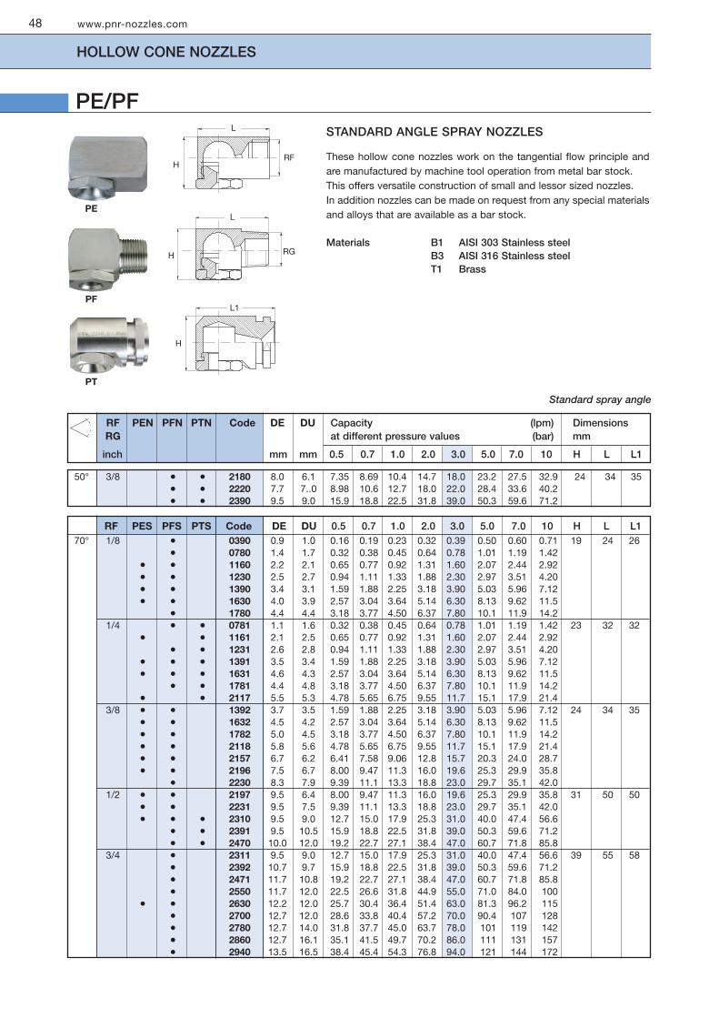
STANDARD ANGLE SPRAY NOZZLES
These hollow cone nozzles work on the tangential flow principle andare manufactured by machine tool operation from metal bar stock. This offers versatile construction of small and lessor sized nozzles.In addition nozzles can be made on request from any special materialsand alloys that are available as a bar stock.
Materials B1 AISI 303 Stainless steel B3 AISI 316 Stainless steel T1 Brass
www.pnr-nozzles.com
HOLLOW CONE NOZZLES
PE/PF
48
PF
PE
PT
Standard spray angle
H
H
H
L
L
L1
RG
RF
RF PEN PFN PTN Code DE DU Capacity (lpm) DimensionsRG at different pressure values (bar) mm
inch mm mm 0.5 0.7 1.0 2.0 3.0 5.0 7.0 10 H L L1
50° 3/8 • • 2180 8.0 6.1 7.35 8.69 10.4 14.7 18.0 23.2 27.5 32.9 24 34 35• • 2220 7.7 7..0 8.98 10.6 12.7 18.0 22.0 28.4 33.6 40.2• • 2390 9.5 9.0 15.9 18.8 22.5 31.8 39.0 50.3 59.6 71.2
RF PES PFS PTS Code DE DU 0.5 0.7 1.0 2.0 3.0 5.0 7.0 10 H L L170° 1/8 • 0390 0.9 1.0 0.16 0.19 0.23 0.32 0.39 0.50 0.60 0.71 19 24 26
• 0780 1.4 1.7 0.32 0.38 0.45 0.64 0.78 1.01 1.19 1.42• • 1160 2.2 2.1 0.65 0.77 0.92 1.31 1.60 2.07 2.44 2.92• • 1230 2.5 2.7 0.94 1.11 1.33 1.88 2.30 2.97 3.51 4.20• • 1390 3.4 3.1 1.59 1.88 2.25 3.18 3.90 5.03 5.96 7.12• • 1630 4.0 3.9 2.57 3.04 3.64 5.14 6.30 8.13 9.62 11.5
• 1780 4.4 4.4 3.18 3.77 4.50 6.37 7.80 10.1 11.9 14.21/4 • • 0781 1.1 1.6 0.32 0.38 0.45 0.64 0.78 1.01 1.19 1.42 23 32 32
• • 1161 2.1 2.5 0.65 0.77 0.92 1.31 1.60 2.07 2.44 2.92• • 1231 2.6 2.8 0.94 1.11 1.33 1.88 2.30 2.97 3.51 4.20
• • • 1391 3.5 3.4 1.59 1.88 2.25 3.18 3.90 5.03 5.96 7.12• • • 1631 4.6 4.3 2.57 3.04 3.64 5.14 6.30 8.13 9.62 11.5
• • 1781 4.4 4.8 3.18 3.77 4.50 6.37 7.80 10.1 11.9 14.2• • 2117 5.5 5.3 4.78 5.65 6.75 9.55 11.7 15.1 17.9 21.4
3/8 • • 1392 3.7 3.5 1.59 1.88 2.25 3.18 3.90 5.03 5.96 7.12 24 34 35• • 1632 4.5 4.2 2.57 3.04 3.64 5.14 6.30 8.13 9.62 11.5• • 1782 5.0 4.5 3.18 3.77 4.50 6.37 7.80 10.1 11.9 14.2• • 2118 5.8 5.6 4.78 5.65 6.75 9.55 11.7 15.1 17.9 21.4• • 2157 6.7 6.2 6.41 7.58 9.06 12.8 15.7 20.3 24.0 28.7• • 2196 7.5 6.7 8.00 9.47 11.3 16.0 19.6 25.3 29.9 35.8
• 2230 8.3 7.9 9.39 11.1 13.3 18.8 23.0 29.7 35.1 42.01/2 • • 2197 9.5 6.4 8.00 9.47 11.3 16.0 19.6 25.3 29.9 35.8 31 50 50
• • 2231 9.5 7.5 9.39 11.1 13.3 18.8 23.0 29.7 35.1 42.0• • • 2310 9.5 9.0 12.7 15.0 17.9 25.3 31.0 40.0 47.4 56.6
• • 2391 9.5 10.5 15.9 18.8 22.5 31.8 39.0 50.3 59.6 71.2• • 2470 10.0 12.0 19.2 22.7 27.1 38.4 47.0 60.7 71.8 85.8
3/4 • 2311 9.5 9.0 12.7 15.0 17.9 25.3 31.0 40.0 47.4 56.6 39 55 58• 2392 10.7 9.7 15.9 18.8 22.5 31.8 39.0 50.3 59.6 71.2• 2471 11.7 10.8 19.2 22.7 27.1 38.4 47.0 60.7 71.8 85.8• 2550 11.7 12.0 22.5 26.6 31.8 44.9 55.0 71.0 84.0 100
• • 2630 12.2 12.0 25.7 30.4 36.4 51.4 63.0 81.3 96.2 115• 2700 12.7 12.0 28.6 33.8 40.4 57.2 70.0 90.4 107 128• 2780 12.7 14.0 31.8 37.7 45.0 63.7 78.0 101 119 142• 2860 12.7 16.1 35.1 41.5 49.7 70.2 86.0 111 131 157• 2940 13.5 16.5 38.4 45.4 54.3 76.8 94.0 121 144 172

www.pnr-nozzles.com
HOLLOW CONE NOZZLES
49
PE/PF
Wide spray angle
WIDE ANGLE SPRAY NOZZLES
ZPM
Pipe clamp
Our Accessories Catalogue (CTG AC20) shows several types of pipeclamps allowing for an easy assembly of hollow cone nozzles onto apipe manifold.
RF PEW PFW PTW Code DE DU Capacity (lpm) DimensionsRG at different pressure values (bar) mm
inch mm mm 0.5 0.7 1.0 2.0 3.0 5.0 7.0 10 H L L1
120° 1/8 • • 0390 09 1.1 0.16 0.19 0.23 0.32 0.39 0.50 0.60 0.71 19 24 26• • 0780 1.4 1.5 0.32 0.38 0.45 0.64 0.78 1.01 1.19 1.42• • 1200 1.5 3.9 0.82 0.97 1.15 1.63 2.00 2.58 3.06 3.65• • 1230 2.0 3.4 0.94 1.11 1.33 1.88 2.30 2.97 3.51 4.20• • 1270 2.2 3.8 1.10 1.30 1.56 2.20 2.70 3.49 4.12 4.93• • 1320 2.1 4.5 1.31 1.55 1.85 2.61 3.20 4.13 4.89 5.84• • 1390 3.6 3.1 1.59 1.88 2.25 3.18 3.90 5.03 5.96 7.12• • 1510 3.4 5.0 2.08 2.46 2.94 4.16 5.10 6.58 7.79 9.31• • 1700 4.5 5.2 2.86 3.38 4.04 5.72 7.00 9.04 10.7 12.8
1/4 • • • 0781 1.4 1.5 0.32 0.38 0.45 0.64 0.78 1.01 1.19 1.42 23 32 32• • • 1130 1.4 3.6 0.53 0.63 0.75 1.06 1.30 1.68 1.99 2.37• • • 1160 1.4 4.0 0.65 0.77 0.92 1.31 1.60 2.07 2.44 2.92• • • 1190 2.0 2.3 0.78 0.92 1.10 1.55 1.90 2.48 2.90 3.50• • • 1271 2.2 3.8 1.10 1.30 1.56 2.20 2.70 3.49 4.12 4.93• • • 1321 2.2 4.5 1.31 1.55 1.85 2.61 3.20 4.13 4.89 5.84• • • 1391 3.6 3.1 1.59 1.88 2.25 3.18 3.90 5.03 5.96 7.12• • • 1511 3.4 5.0 2.08 2.46 2.94 4.16 5.10 6.58 7.79 9.31• • • 1600 3.4 5.2 2.45 2.90 3.46 4.90 6.00 7.75 9.17 11.0• • • 1701 4.2 5.2 2.86 3.38 4.04 5.72 7.00 9.04 10.7 12.8• • • 1780 3.7 6.0 3.18 3.77 4.50 6.37 7.80 10.1 11.9 14.2• • • 1860 4.0 5.6 3.51 4.15 4.97 7.02 8.60 11.1 13.1 15.7• • • 1940 5.0 5.7 3.84 4.54 5.43 7.68 9.40 12.1 14.4 17.2• • • 2117 5.8 2.4 4.78 5.65 6.75 9.55 11.7 15.1 17.9 21.4
3/8 • • 1512 3.5 5.0 2.08 2.46 2.94 4.16 5.10 6.58 7.79 9.31 24 34 35• • 1601 3.5 5.2 2.45 2.90 3.46 4.90 6.00 7.75 9.17 11.0• • 1702 4.2 5.2 2.86 3.38 4.04 5.72 7.00 9.04 10.7 12.8• • 1781 3.7 6.0 3.18 3.77 4.50 6.37 7.80 10.1 11.9 14.2• • 1861 4.0 5.6 3.51 4.15 4.97 7.02 8.60 11.1 13.1 15.7• • 1941 5.0 5.7 3.84 4.54 5.43 7.68 9.40 12.1 14.4 17.2• • 2102 4.5 6.9 4.16 4.93 5.89 8.33 10.2 13.2 15.6 19.0• • 2110 5.0 6.2 4.49 5.31 6.35 8.98 11.0 14.2 16.8 20.0• • • 2118 5.0 6.7 4.78 5.65 6.75 9.55 11.7 15.1 17.9 21.4• • • 2133 6.1 8.0 5.43 6.42 7.68 10.9 13.3 17.2 20.3 24.3• • • 2157 5.0 9.0 6.41 7.58 9.06 12.8 15.7 20.3 24.0 28.7• • • 2172 6.2 7.5 7.02 8.31 9.93 14.0 17.2 22.2 26.3 31.4• • • 2196 6.2 8.4 8.00 9.47 11.3 16.0 19.6 25.3 29.9 35.8• • • 2220 6.2 9.7 8.98 10.6 12.7 18.0 22.0 28.4 33.6 40.2
1/2 • • 2391 9.0 10.5 15.9 18.8 22.5 31.8 39.0 50.3 59.6 71.2 31 50 503/4 • 2630 10.3 15.0 25.7 30.4 36.4 51.4 63.0 81.3 96.2 115 39 55 58

MOULDED PLASTIC NOZZLES
This range of hollow cone nozzles are made by plasticmoulding, out of top quality glassfiber reinforced polypropylenewith good mechanical strength and dimensional stability.They produce small droplets , uniform distribution and arecorrosion resistant : prices are moderate and are ideal forapplications like air humidification, intensive product coolingand gas washing. Together with our pipe clamps, they offerthe best solution in all cases where large quantity of nozzleshave to be easily assembled onto pipe manifolds.Maximum operating temperature 75° C.
Materials D6 Fiberglass reinforced PP
PO Male thread nozzles
For all 3/8” size nozzles we can supply PO type nozzles with3/8” male thread.
www.pnr-nozzles.com
HOLLOW CONE NOZZLES
50
PN/PO
H
L
WS
L1
RF PNS POS Code DE DU Capacity (lpm) DimensionsRG at different pressure values (bar) mm
inch mm mm 0.5 0.7 1.0 2.0 3.0 5.0 7.0 10 H L L1 WS70° 3/8 • • 1170 2.0 2.9 0.69 0.82 0.98 1.39 1.70 2.19 2.60 3.10 31 44 20 22
PNT POT Code DE DU 0.5 0.7 1.0 2.0 3.0 5.0 7.0 10 H L L1 WS80° 3/8 • • 1260 2.7 3.5 1.06 1.26 1.50 2.12 2.60 3.36 3.97 4.75 31 44 20 22
PNU POU Code DE DU 0.5 0.7 1.0 2.0 3.0 5.0 7.0 10 H L L1 WS90° 3/8 • 1390 3.7 3.8 1.59 1.88 2.25 3.18 3.90 5.03 5.96 7.12 31 44 20 22
• • 1670 4.4 5.2 2.74 3.24 3.87 5.47 6.70 8.65 10.2 12.2• • 1850 5.2 5.6 3.47 4.11 4.91 6.94 8.50 11.0 13.0 15.5• • 2115 6.1 6.3 4.69 5.56 6.64 9.39 11.5 14.8 17.6 21.0• • 2220 7.2 9.2 8.98 10.6 12.7 18.0 22.0 28.4 33.6 40.2
1/2 • 2320 9.5 10.5 13.1 15.5 18.5 26.1 32.0 41.3 48.9 58.4 42 55 35 30• 2398 8.5 14.0 16.2 19.2 23.0 32.5 39.8 51.4 60.8 72.7
PNY POY Code DE DU 0.5 0.7 1.0 2.0 3.0 5.0 7.0 10 H L L1 WS130° 3/8 • • 1170 1.7 3.5 0.69 0.82 0.98 1.39 1.70 2.19 2.60 3.10 31 44 20 22
• • 1260 1.9 5.0 1.06 1.26 1.50 2.12 2.60 3.36 3.97 4.75• • 1390 2.7 5.0 1.59 1.88 2.25 3.18 3.90 5.03 5.96 7.12• • 1460 3.1 5.0 1.88 2.22 2.66 3.76 4.60 5.94 7.03 8.40• • 1570 3.0 7.5 2.33 2.75 3.29 4.65 5.70 7.36 8.71 10.4• • 1670 3.4 7.5 2.74 3.24 3.87 5.47 6.70 8.65 10.2 12.2• • 1850 4.1 7.5 3.47 4.11 4.91 6.94 8.50 11.0 13.0 15.5• • 1980 3.6 12 4.00 4.73 5.66 8.00 9.80 12.7 15.0 17.9• • 2128 4.2 12 5.23 6.18 7.39 10.5 12.8 16.5 19.6 23.4• • 2208 6.0 12 8.49 10.0 12.0 17.0 20.8 26.9 31.8 38.0• • 2220 6.4 12 8.98 10.6 12.7 18.0 22.0 28.4 33.6 40.2
1/2 • 2129 4.3 14 5.23 6.18 7.39 10.5 12.8 16.5 19.6 23.4 42 55 35 30• 2209 5.8 14 8.49 10.0 12.0 17.0 20.8 26.9 31.8 38.0• 2221 6.3 14 8.98 10.6 12.7 18.0 22.0 28.4 33.6 40.2• 2320 7.6 14 13.1 15.5 18.5 26.1 32.0 41.3 48.9 58.4• 2420 9.0 14 17.1 20.3 24.2 34.3 42.0 54.2 64.2 76.7
RF

www.pnr-nozzles.com
HOLLOW CONE NOZZLES
51
RAIN LINE SPRAY/INSIDE VANE
RA nozzles work on the tangential jet principle andproduce a very fine spray with a hollow cone spraypattern, in line with the inlet pipe. The carefully machinedinside vane has two precision machined spiral grooves,which produce a wide range of capacities starting fromvery low values. When low capacity nozzles are used,because of the limited inner passages, it is recommendedthat the spray manifold should be fitted with a filter of theproper mesh size.
Materials B31 AISI 316 L Stainless steel T1 Brass
H
WS
RF
Code RF D D1 Capacity (lpm) Dimensionsinch mm mm at different pressure values (bar) mm
0.5 0.7 1.0 2.0 3.0 5.0 7.0 10 H WS
80° RAT 0200 xx 1/8 1.0 0.5 0.08 0.10 0.12 0.16 0.20 0.26 0.31 0.37 18 17RAT 0390 xx 1.7 0.5 0.16 0.19 0.23 0.32 0.39 0.50 0.60 0.71
60° RAQ 0490 xx 3/8 1.1 0.6 0.20 0.24 0.28 0.40 0.49 0.63 0.75 0.89 29 22RAQ 0770 xx 1.6 0.6 0.31 0.37 0.44 0.63 0.77 0.99 1.18 1.41RAQ 1122 xx 2.0 0.6 0.50 0.59 0.70 1.00 1.22 1.58 1.86 2.23
90° RAU 1208 xx 3/8 3.0 1.0 0.85 1.00 1.20 1.70 2.08 2.69 3.18 3.80 29 22RAU 1306 xx 4.0 1.6 1.25 1.48 1.77 2.50 3.06 3.95 4.67 5.59RAU 1490 xx 4.2 1.6 2.00 2.37 2.83 4.00 4.90 6.33 7.48 8.95RAU 1612 xx 4.7 1.6 2.50 2.96 3.53 5.00 6.12 7.90 9.35 11.2RAU 1772 xx 5.5 1.6 3.15 3.73 4.46 6.30 7.72 10.0 11.8 14.1RAU 2104 xx 6.3 1.6 4.25 5.02 6.00 8.49 10.4 13.4 15.9 19.0RAU 1491 xx 1/2 5.0 1.8 2.00 2.37 2.83 4.00 4.90 6.33 7.48 8.95 36 27RAU 1551 xx 5.5 1.8 2.25 2.66 3.18 4.49 5.50 7.10 8.40 10.0RAU 1686 xx 6.0 1.8 2.80 3.31 3.96 5.60 6.86 8.86 10.5 12.5RAU 1980 xx 6.3 2.0 4.00 4.73 5.66 8.00 9.80 12.7 15.0 17.9RAU 2137 xx 6.7 2.0 5.59 6.62 7.91 11.2 13.7 17.7 20.9 25.0RAU 2153 xx 7.5 2.0 6.45 7.63 9.12 12.9 15.8 20.4 24.1 28.8RAU 2196 xx 9.0 2.0 8.00 9.47 11.3 16.0 19.6 25.3 29.9 35.8

IN LINE SPRAY / VANELESS
These nozzles produce a hollow cone spray pattern, in line with thenozzle inlet pipe.Their design, without any inside whirling vane, offers wideunobstructed passages and minimizes clogging danger whileproducing fine droplets. The above characteristics make these nozzles the ideal solution fordust suppression applications, specially suited for coal dust control.
Materials B1 AISI 303 Stainless steel T1 Brass
* Double inlet orifice
www.pnr-nozzles.com
HOLLOW CONE NOZZLES
52
RB
60° RBQ 1160 xx 3/8 2.0 2.0 0.65 0.77 0.93 1.31 1.60 2.07 2.44 2.92 31 17RBQ 1230 xx 2.4 2.4 0.94 1.11 1.33 1.88 2.30 2.97 3.51 4.20RBQ 1390 xx 3.3 2.9 1.59 1.88 2.25 3.18 3.90 5.03 5.96 7.12RBQ 1630 xx 3.9 3.8 2.57 3.04 3.64 5.14 6.30 8.13 9.62 11.5RBQ 1780 xx 4.4 4.0 3.18 3.77 4.50 6.37 7.80 10.1 11.9 14.2RBQ 2110 xx 4.4 *4.0 4.49 5.31 6.35 8.98 11.0 14.2 16.8 20.1
70° RBS 1391 xx 1/2 3.3 3.2 1.59 1.88 2.25 3.18 3.90 5.03 5.96 7.12 37 22RBS 1631 xx 4.0 4.0 2.57 3.04 3.64 5.14 6.30 8.13 9.62 11.5RBS 1781 xx 4.5 4.5 3.18 3.77 4.50 6.37 7.80 10.1 11.9 14.2RBS 2117 xx 5.1 *4.4 4.82 5.70 6.81 9.63 11.8 15.2 18.0 21.5RBS 2157 xx 6.1 *4.7 6.45 7.63 9.12 12.9 15.8 20.4 24.1 28.8RBS 2196 xx 7.1 *5.2 7.96 9.42 11.3 15.9 19.5 25.2 29.8 35.6RBS 1392 xx 3/4 3.3 3.3 1.59 1.88 2.25 3.18 3.90 5.03 5.96 7.12 43 32RBS 1632 xx 4.2 4.2 2.57 3.04 3.64 5.14 6.30 8.13 9.62 11.5RBS 1782 xx 4.7 4.5 3.18 3.77 4.50 6.37 7.80 10.1 11.9 14.2RBS 2118 xx 5.4 5.4 4.82 5.70 6.81 9.63 11.8 15.2 18.0 21.5RBS 2158 xx 6.4 6.4 6.45 7.63 9.12 12.9 15.8 20.4 24.1 28.8RBS 2197 xx 7.7 7.1 7.96 9.42 11.3 15.9 19.5 25.2 29.8 35.6RBS 2390 xx 9.5 *7.1 15.9 18.8 22.5 31.8 39.0 50.3 59.6 71.2
80° RBT 2310 xx 1+1/2 10.0 *7.9 12.7 15.0 17.9 25.3 31.0 40.0 47.4 56.6 69 50RBT 2391 xx 9.5 *9.5 15.9 18.8 22.5 31.8 39.0 50.3 59.6 71.2RBT 2470 xx 11.1 *9.5 19.2 22.7 27.1 38.4 47.0 60.7 71.8 85.8RBT 2550 xx 12.7 *9.5 22.5 26.6 31.8 44.9 55.0 71.0 84.0 100RBT 2630 xx 14.3 *9.5 25.7 30.4 36.4 51.4 63.0 81.3 96.2 115RBT 2700 xx 15.0 *9.5 28.6 33.8 40.4 57.2 70.0 90.4 107 128RBT 2780 xx 15.9 *9.5 31.8 37.7 45.0 63.7 78.0 101 119 142RBT 2860 xx 17.1 *9.5 35.1 41.5 49.7 70.2 86.0 111 131 157RBT 2940 xx 18.3 *9.5 38.4 45.4 54.3 76.8 94.0 121 144 172
Code RG D D1 Capacity (lpm) Dimensionsinch mm mm at different pressure values (bar) mm
0.5 0.7 1.0 2.0 3.0 5.0 7.0 10 H WS
H
WS
RG

www.pnr-nozzles.com
HOLLOW CONE NOZZLES
53
RCIN LINE SPRAY
RC type nozzles produce a hollow cone spray pattern, in line with thenozzle inlet pipe.The spray is produced by deflection of the water flow against a fixedplate in front of the nozzle orifice, which allows at the same time toobtain an high efficiency, small drop size and very wide spray angles.
Materials B1 AISI 303 Stainless steel T1 Brass
Common applications
RC series hollow cone nozzles are used mainly for air washing, dustsuppression and cooling processes. The accessories shown below can be used for their protection againstclogging, or for an appropriate assembly.Please see our accessories Catalogue CTG AC20.
Assembly fittings
VEM ZRP ZPM
1/4” 3/8” Code Capacity (lpm) Dimensionsat different pressure values (bar) mm
0.5 0.7 1.0 2.0 3.0 5.0 7.0 10 H WS
• RCY 1780 xx 4.50 6.37 7.80 10.1 11.9 14.2 33 17• RCY 2117 xx 5.70 6.81 9.63 11.8 15.2 18.0 21.5• RCY 2157 xx 7.58 9.06 12.8 15.7 20.3 24.0 28.7• RCY 2196 xx 9.42 11.3 15.9 19.5 25.2 29.8 35.6
• RCY 2230 xx 9.39 11.1 13.3 18.8 23.0 29.7 35.1 42.0 44 22• RCY 2270 xx 11.0 13.0 15.6 22.0 27.0 34.9 41.2 49.3• RCY 2310 xx 12.7 15.0 17.9 25.3 31.0 40.0 47.4 56.6• RCY 2350 xx 14.3 16.9 20.2 28.6 35.0 45.2 53.5 63.9• RCY 2390 xx 15.9 18.8 22.5 31.8 39.0 50.3 59.6 71.2
• RCZ 1780 xx 4.50 6.37 7.80 10.1 11.9 14.2 33 17• RCZ 2117 xx 5.70 6.81 9.63 11.8 15.2 18.0 21.5• RCZ 2157 xx 7.58 9.06 12.8 15.7 20.3 24.0 28.7• RCZ 2196 xx 9.42 11.3 15.9 19.5 25.2 29.8 35.6
• RCZ 2230 xx 9.39 11.1 13.3 18.8 23.0 29.7 35.1 42.0 44 22• RCZ 2270 xx 11.0 13.0 15.6 22.0 27.0 34.9 41.2 49.3• RCZ 2310 xx 12.7 15.0 17.9 25.3 31.0 40.0 47.4 56.6• RCZ 2350 xx 14.3 16.9 20.2 28.6 35.0 45.2 53.5 63.9• RCZ 2390 xx 15.9 18.8 22.5 31.8 39.0 50.3 59.6 71.2
150°
180°
HWS
RG

HYDRAULIC ATOMIZERS
Hydraulic atomizers are designed to deliver a very finely atomizedhollow cone spray, even at low pressure values.The nozzle contains a precisely machined insert with tiny passages,which can be disassembled for cleaning should the nozzle be clogged.Protection against clogging can be achieved either through a straineron the main manifold, or by means of an optional individual filter VEF(see accessories catalogue CTG AC20).We offer two types of bodies, RX with tapered thread and spray angle80°, and RZ with straight thread and different spray angle values.
Materials B1 AISI 303 Stainless steel (RX)B3 AISI 316 Stainless steel (RZ)T1 Brass (RX)
Additional spray angles
RZ nozzles with orifice equal or larger than 1,0 mm can be producedwith angles of 30°, 45°, 60° or 90°. The table beside shows the nozzleidentifying codes for these spray angles.
Capacities shown inthe above table aregiven in liters per hour.
Capacities shown inthe above table aregiven in l iters perminute.
www.pnr-nozzles.com
HOLLOW CONE NOZZLES
54
RX/RZ
RZF RZM RZQ RZU30° 45° 60° 90°
Spray angle codes
RZ
RX
WS 14
1/4”
54.5
19.5
WS 17
1/4”
24
VEF
60° RZQ 0080 xx 0.45 0.07 0.08 0.09 0.10 0.11 0.15 0.18 0.21 0.33RZQ 0120 xx 0.55 0.10 0.12 0.14 0.15 0.17 0.22 0.27 0.31 0.49RZQ 0250 xx 0.80 0.18 0.20 0.25 0.29 0.32 0.35 0.46 0.56 0.65 1.02RZQ 0390 xx 1.00 0.28 0.32 0.39 0.45 0.50 0.55 0.71 0.87 1.01 1.59RZQ 0560 xx 1.20 0.40 0.46 0.56 0.65 0.72 0.79 1.02 1.25 1.45 2.29RZQ 0780 xx 1.40 0.55 0.64 0.78 0.90 1.01 1.10 1.42 1.74 2.01 3.18RZQ 1100 xx 1.60 0.71 0.82 1.00 1.15 1.29 1.41 1.83 2.24 2.58 4.08RZQ 1140 xx 1.90 0.99 1.14 1.40 1.62 1.81 1.98 2.56 3.13 3.61 5.72RZQ 1170 xx 2.10 1.20 1.39 1.70 1.96 2.19 2.40 3.10 3.80 4.39 6.94RZQ 1200 xx 2.30 1.41 1.63 2.00 2.31 2.58 2.83 3.65 4.47 5.16 8.16
80° RXT 0060 xx 0.50 2.94 3.60 4.16 4.65 5.09 6.57 8.05 9.30 14.7RXT 0100 xx 0.50 4.90 6.00 6.93 7.75 8.49 11.0 13.4 15.5 24.5RXT 0130 xx 0.70 5.52 6.37 7.80 9.01 10.1 11.0 14.2 17.4 20.1 31.8RXT 0190 xx 0.70 8.06 9.31 11.4 13.2 14.7 16.1 20.8 25.5 29.4 46.5RXT 0250 xx 1.00 10.6 12.2 15.0 17.3 19.4 21.2 27.4 33.5 38.7 61.2RXT 0380 xx 1.00 16.1 18.6 22.8 26.3 29.4 32.2 41.6 51.0 58.9 93.1RXT 0510 xx 1.50 21.6 25.0 30.6 35.3 39.5 43.3 55.9 68.4 79.0 125RXT 0650 xx 1.60 27.6 31.8 39.0 45.0 50.3 55.2 71.2 87.2 101 159RXT 0780 xx 1.90 33.1 38.2 46.8 54.0 60.4 66.2 85.4 105 121 191RXT 0910 xx 1.90 38.6 44.6 54.6 63.0 70.5 77.2 99.7 122 141 223RXT 1116 xx 1.90 49.2 56.8 69.6 80.4 89.9 98.4 127 156 180 284RXT 1143 xx 1.90 60.7 70.1 85.8 99.1 111 121 157 192 222 350RXT 1166 xx 2.20 70.4 81.3 99.6 115 129 141 182 223 257 407
Code D Capacity (lph)mm at different pressure values (bar)
1.5 2.0 3.0 4.0 5.0 6.0 10 15 20 50
Code D Capacity (lpm)mm at different pressure values (bar)
1.5 2.0 3.0 4.0 5.0 6.0 10 15 20 50

www.pnr-nozzles.com
PNR PRODUCT RANGE
55
PNR manufactures, in addition to the range of general purpose nozzles shown in this Catalogue, a wide range of otherproducts and systems allowing you to optimize the use of liquid spray and fluid control in most modern industrial processes. You will find our high quality, proven products shown in the following catalogs:
CTG AC20 Accessories CatalogueA complete line of nipples,clamps, swivel joints andeverything that helps you to easilyassemble, align and service yourspraying systems.Air blowers, mixing eductors,filters, cleaning guns and lances,hose reels, steam heaters,pressure tanks, quick couplingsto help build a professionalsystem.
CTG LS20 Tank washing systemsEverything from the simple fixedsprayballs and pintle nozzles tothe twin-axis washer heads.Reaction driven, water drivenand electric or pneumatic motordriven. Professional insidesurface cleaning of industrialtanks with the latest technology,together with state of the artaccessories.
CTG AZ18 Air assisted atomizersUltrasonic, classic and automaticatomizers for the finestatomization in any process.High quality machining and tightquality control assure aprofessional result to yoursystem. Control cabinets andspray programmers allow forcomplete humidification systemsto be easily assembled.
CTG LN16 Gas cooling lancesSpillback or air assisted lancesfor gas cooling processes insteelworks, cement plants andother industrial applications.We can supply spare parts,retrofit your system or evensupply a complete system, PLCdriven, to upgrade towerperformance to the latesttechnical standards.
CTG SP10 Spraydry nozzlesHigh pressure or air assistedprecision nozzles manufacturedwith top quality stainless steelhousings and tungsten carbideinternals. A complete line of nozzlesto retrofit existing plants atcompetitive prices. Only the highestquality materials and the mostprecise machining are employed inthe manufacture of our nozzles, toassure precisely defined results andconsistent wear life.
CTG PM10 Papermill productsA sixteen page Catalogueshowing products speciallydeveloped for perfect resultson paper making machines,including our patented discnozzle for self-cleaning pipes,needle nozzles with sapphireand ruby orifice, oscil latingpipes with high qualitycomputer driven motor.
CTG SW20 Steelwork nozzlesA complete l ine of nozzlesfor steelwork applications,including continuous castingair atomizers and conventionalnozzles, descaling nozzles forhigh pressure systems, fixedposit ion dovetai l t ips andcoke quenching high capacityflanged nozzles.
CTG FF10 Fire fighting productsEverything for fixed and mobilefoam systems, bladder tanks,any k ind o f foam mixer,monitors, foam lances and foamnozzles, mobile trailers forfoam systems, pressure waternozzles and watermist nozzles,hydrants.

www.pnr-nozzles.com
NOTE
56

ABBREVIATIONS
www.pnr-nozzles.com
01 COMPANY
02 NAME
03 FUNCTION
04 ADRESS
05 PHONE FAX
06 WEB SITE E-MAIL
PRODUCT RANGE
GENERAL PURPOSE SPRAY NOZZLES
AIR ASSISTED ATOMIZERS
COMPLEMENTARY PRODUCTSAND ASSEMBLY FITTINGS
INDUSTRIAL TANK WASHING SYSTEMS
EVAPORATIVE COOLING SYSTEMS
FIRE FIGHTING PRODUCTS
PAPERMILL PRODUCTS
STEELWORK NOZZLES
SPRAYDRY NOZZLES
GENERAL INFORMATION
SENDING LIST
In order to automatically receive updates of our technical Documentation please photocopy this card and send it to us inside asealed envelope, your details shall be kept on our Permanent Mailing List.
CTG UG20
DU Liquid outlet dia mm
FF Flange outer dia mm
G Flange center-hole dia mm
H, H1 Height mm
L, L1 Length mm
NR Number of orifices -
QC Quickfit connection -
RF Female BSP straight thread inch
RG BSPT male taper thread inch
SQ Square bar size mm
W Weight gram, kg
WS Wrench size mm
CL Jet deflection angle deg
D Conventional orifice dia mm
D1 Smallest free inside dia mm
DE Liquid inlet dia mm
DF Flange size inch
DIA Outside diameter mm
DN Flange nominal size mm
PRODUCT WARRANTY
PNR products will be replaced or repaired at the option of PNR and free of charges if found defective in manufacturing,labelling or packaging. The above warranty conditions will apply if notice of defect is received by PNR within 30 days fromdate of product installations or one year from date of shipment. The cost of above said replacement or repair shall be theexclusive remedy for any breach of any warranty, and PNR shall not be held liable for any damage due to personal injuries orcommercial losses coming from product malfunction.
Our Company Procedure for warranty cases requires the following steps to be performed:1 Contact our Quality manager and obtain from PNR a return authorization number2 Return the products together with our Form 3DA A04 duly completed3 PNR shall issue a test report, send you a copy and return the product repaired or replaced.
Our Company scope is to offer full Customer satisfaction, and we are fully aware of the inconvenience which can be originatedfrom a defective product. Please be assured we shall do our best to make available a perfect product in the shortest possibletime.
PRODUCT RETURN POLICY
PRODUCTS DELIVERED IN ERROR FROM PNR1 Obtain from PNR a return authorization number together with a Form 3DA A042 Return the products together with our Form 3DA A04 duly completed3 PNR shall issue a Credit Note for full Product and shipping costs.
PRODUCTS ORDERED INCORRECTLY TO PNR 1 Obtain from PNR a return authorization number together with a Form 3DA A042 Return the products at your expense together with the form 3DA A04 duly completed3 Products shall be returned in original condition, inside the original packaging4 A re-stocking change of 10% applies.
NON CATALOG PRODUCTS These products can only be returned after a written authorisation from PNR has been obtained.
DISCLAIMER
Our products are manufactured with the best care and according to the latest developments of the technology, but we cannotassure that every one of our products is perfectly fit for any possible specific process. The information in this Catalogue isprovided "as is" and we make no warranty of any kind with respect to the subject matter or accuracy of the informationcontained herein. This publication may include technical inaccuracies or typographical errors and changes may be periodicallymade to the information herein without prior notice.
57

Our products are distributed through:
We are moreover represented in:
PNR America PNR Benelux PNR ItaliaPNR Asia PNR Czech Republic PNR Mexico
PNR Baltic PNR Deutschland PNR U. KingdomPNR France
Argentina Australia Austria Brazil
BulgariaCanada
Chile China
CroatiaDenmarkFinlandGreece
India Indonesia
IranIrelandKorea
MalaysiaNorway
New ZealandPakistan
PhilippinesPoland
Portugal
RumeniaRussiaSerbia
SingaporeSlovenja
SpainSouth Africa
SwedenTaiwan Turkey
Venezuela
CTG UG20 BRwww.pnr-nozzles.com