Embed Size (px)
Citation preview
ESP8266 Arduino Core DocumentationRelease 2.4.0
Ivan Grokhotkov
May 14, 2017


Contents:
1 Installing 11.1 Boards Manager . . . . . . . . . . . . . . . . . . . . . . . . . . . . . . . . . . . . . . . . . . . . . 11.2 Using git version . . . . . . . . . . . . . . . . . . . . . . . . . . . . . . . . . . . . . . . . . . . . . 2
2 Reference 52.1 Digital IO . . . . . . . . . . . . . . . . . . . . . . . . . . . . . . . . . . . . . . . . . . . . . . . . . 52.2 Analog input . . . . . . . . . . . . . . . . . . . . . . . . . . . . . . . . . . . . . . . . . . . . . . . 62.3 Analog output . . . . . . . . . . . . . . . . . . . . . . . . . . . . . . . . . . . . . . . . . . . . . . 62.4 Timing and delays . . . . . . . . . . . . . . . . . . . . . . . . . . . . . . . . . . . . . . . . . . . . 62.5 Serial . . . . . . . . . . . . . . . . . . . . . . . . . . . . . . . . . . . . . . . . . . . . . . . . . . . 62.6 Progmem . . . . . . . . . . . . . . . . . . . . . . . . . . . . . . . . . . . . . . . . . . . . . . . . . 7
3 Libraries 93.1 WiFi(ESP8266WiFi library) . . . . . . . . . . . . . . . . . . . . . . . . . . . . . . . . . . . . . . . 93.2 Ticker . . . . . . . . . . . . . . . . . . . . . . . . . . . . . . . . . . . . . . . . . . . . . . . . . . . 93.3 EEPROM . . . . . . . . . . . . . . . . . . . . . . . . . . . . . . . . . . . . . . . . . . . . . . . . . 93.4 I2C (Wire library) . . . . . . . . . . . . . . . . . . . . . . . . . . . . . . . . . . . . . . . . . . . . 103.5 SPI . . . . . . . . . . . . . . . . . . . . . . . . . . . . . . . . . . . . . . . . . . . . . . . . . . . . 103.6 SoftwareSerial . . . . . . . . . . . . . . . . . . . . . . . . . . . . . . . . . . . . . . . . . . . . . . 103.7 ESP-specific APIs . . . . . . . . . . . . . . . . . . . . . . . . . . . . . . . . . . . . . . . . . . . . 103.8 mDNS and DNS-SD responder (ESP8266mDNS library) . . . . . . . . . . . . . . . . . . . . . . . . 113.9 SSDP responder (ESP8266SSDP) . . . . . . . . . . . . . . . . . . . . . . . . . . . . . . . . . . . . 113.10 DNS server (DNSServer library) . . . . . . . . . . . . . . . . . . . . . . . . . . . . . . . . . . . . . 113.11 Servo . . . . . . . . . . . . . . . . . . . . . . . . . . . . . . . . . . . . . . . . . . . . . . . . . . . 123.12 Other libraries (not included with the IDE) . . . . . . . . . . . . . . . . . . . . . . . . . . . . . . . 12
4 Filesystem 154.1 Flash layout . . . . . . . . . . . . . . . . . . . . . . . . . . . . . . . . . . . . . . . . . . . . . . . 154.2 File system limitations . . . . . . . . . . . . . . . . . . . . . . . . . . . . . . . . . . . . . . . . . . 164.3 Uploading files to file system . . . . . . . . . . . . . . . . . . . . . . . . . . . . . . . . . . . . . . 164.4 File system object (SPIFFS) . . . . . . . . . . . . . . . . . . . . . . . . . . . . . . . . . . . . . . . 174.5 Filesystem information structure . . . . . . . . . . . . . . . . . . . . . . . . . . . . . . . . . . . . . 184.6 Directory object (Dir) . . . . . . . . . . . . . . . . . . . . . . . . . . . . . . . . . . . . . . . . . . 194.7 File object . . . . . . . . . . . . . . . . . . . . . . . . . . . . . . . . . . . . . . . . . . . . . . . . 19
5 ESP8266WiFi library 215.1 Introduction . . . . . . . . . . . . . . . . . . . . . . . . . . . . . . . . . . . . . . . . . . . . . . . 21
i

5.2 Class Description . . . . . . . . . . . . . . . . . . . . . . . . . . . . . . . . . . . . . . . . . . . . . 245.3 Diagnostics . . . . . . . . . . . . . . . . . . . . . . . . . . . . . . . . . . . . . . . . . . . . . . . . 285.4 What’s Inside? . . . . . . . . . . . . . . . . . . . . . . . . . . . . . . . . . . . . . . . . . . . . . . 29
6 OTA Updates 336.1 Introduction . . . . . . . . . . . . . . . . . . . . . . . . . . . . . . . . . . . . . . . . . . . . . . . 336.2 Arduino IDE . . . . . . . . . . . . . . . . . . . . . . . . . . . . . . . . . . . . . . . . . . . . . . . 346.3 Web Browser . . . . . . . . . . . . . . . . . . . . . . . . . . . . . . . . . . . . . . . . . . . . . . . 426.4 HTTP Server . . . . . . . . . . . . . . . . . . . . . . . . . . . . . . . . . . . . . . . . . . . . . . . 456.5 Stream Interface . . . . . . . . . . . . . . . . . . . . . . . . . . . . . . . . . . . . . . . . . . . . . 476.6 Updater class . . . . . . . . . . . . . . . . . . . . . . . . . . . . . . . . . . . . . . . . . . . . . . . 47
7 Boards 497.1 Adafruit HUZZAH ESP8266 (ESP-12) . . . . . . . . . . . . . . . . . . . . . . . . . . . . . . . . . 497.2 ESPresso Lite 1.0 . . . . . . . . . . . . . . . . . . . . . . . . . . . . . . . . . . . . . . . . . . . . . 497.3 ESPresso Lite 2.0 . . . . . . . . . . . . . . . . . . . . . . . . . . . . . . . . . . . . . . . . . . . . . 497.4 Phoenix 1.0 . . . . . . . . . . . . . . . . . . . . . . . . . . . . . . . . . . . . . . . . . . . . . . . . 497.5 Phoenix 2.0 . . . . . . . . . . . . . . . . . . . . . . . . . . . . . . . . . . . . . . . . . . . . . . . . 507.6 NodeMCU 0.9 . . . . . . . . . . . . . . . . . . . . . . . . . . . . . . . . . . . . . . . . . . . . . . 507.7 NodeMCU 1.0 . . . . . . . . . . . . . . . . . . . . . . . . . . . . . . . . . . . . . . . . . . . . . . 507.8 Olimex MOD-WIFI-ESP8266-DEV . . . . . . . . . . . . . . . . . . . . . . . . . . . . . . . . . . . 507.9 Olimex MOD-WIFI-ESP8266 . . . . . . . . . . . . . . . . . . . . . . . . . . . . . . . . . . . . . . 517.10 Olimex ESP8266-EVB . . . . . . . . . . . . . . . . . . . . . . . . . . . . . . . . . . . . . . . . . . 517.11 SparkFun ESP8266 Thing . . . . . . . . . . . . . . . . . . . . . . . . . . . . . . . . . . . . . . . . 517.12 SweetPea ESP-210 . . . . . . . . . . . . . . . . . . . . . . . . . . . . . . . . . . . . . . . . . . . . 517.13 ESPino . . . . . . . . . . . . . . . . . . . . . . . . . . . . . . . . . . . . . . . . . . . . . . . . . . 517.14 WifInfo . . . . . . . . . . . . . . . . . . . . . . . . . . . . . . . . . . . . . . . . . . . . . . . . . . 527.15 Generic ESP8266 modules . . . . . . . . . . . . . . . . . . . . . . . . . . . . . . . . . . . . . . . . 527.16 Serial Adapter . . . . . . . . . . . . . . . . . . . . . . . . . . . . . . . . . . . . . . . . . . . . . . 527.17 Minimal Hardware Setup for Bootloading and Usage . . . . . . . . . . . . . . . . . . . . . . . . . . 537.18 ESP to Serial . . . . . . . . . . . . . . . . . . . . . . . . . . . . . . . . . . . . . . . . . . . . . . . 537.19 Minimal . . . . . . . . . . . . . . . . . . . . . . . . . . . . . . . . . . . . . . . . . . . . . . . . . 547.20 Improved Stability . . . . . . . . . . . . . . . . . . . . . . . . . . . . . . . . . . . . . . . . . . . . 557.21 Boot Messages and Modes . . . . . . . . . . . . . . . . . . . . . . . . . . . . . . . . . . . . . . . . 557.22 Generic ESP8285 modules . . . . . . . . . . . . . . . . . . . . . . . . . . . . . . . . . . . . . . . . 567.23 WeMos D1 . . . . . . . . . . . . . . . . . . . . . . . . . . . . . . . . . . . . . . . . . . . . . . . . 567.24 WeMos D1 mini . . . . . . . . . . . . . . . . . . . . . . . . . . . . . . . . . . . . . . . . . . . . . 567.25 ESPino (WROOM-02 Module) by ThaiEasyElec . . . . . . . . . . . . . . . . . . . . . . . . . . . . 567.26 gen4-IoD Range by 4D Systems . . . . . . . . . . . . . . . . . . . . . . . . . . . . . . . . . . . . . 57
8 FAQ 598.1 I am getting “espcomm_sync failed” error when trying to upload my ESP. How to resolve this issue? 598.2 Why esptool is not listed in “Programmer” menu? How do I upload ESP without it? . . . . . . . . . 598.3 My ESP crashes running some code. How to troubleshoot it? . . . . . . . . . . . . . . . . . . . . . 598.4 This Arduino library doesn’t work on ESP. How do I make it working? . . . . . . . . . . . . . . . . 608.5 In the IDE, for ESP-12E that has 4M flash, I can choose 4M (1M SPIFFS) or 4M (3M SPIFFS). No
matter what I select, the IDE tells me the maximum code space is about 1M. Where does my flash go? 608.6 I have observed a case when ESP.restart() doesn’t work. What is the reason for that? . . . . . . . . . 608.7 How to resolve “Board generic (platform esp8266, package esp8266) is unknown” error? . . . . . . . 60
9 Exception Causes (EXCCAUSE) 61
10 Debugging 6310.1 Introduction . . . . . . . . . . . . . . . . . . . . . . . . . . . . . . . . . . . . . . . . . . . . . . . 6310.2 Informations . . . . . . . . . . . . . . . . . . . . . . . . . . . . . . . . . . . . . . . . . . . . . . . 65
ii

11 Stack Dumps 6711.1 Introduction . . . . . . . . . . . . . . . . . . . . . . . . . . . . . . . . . . . . . . . . . . . . . . . 67
12 Using Eclipse with Arduino ESP8266 6912.1 What to Download . . . . . . . . . . . . . . . . . . . . . . . . . . . . . . . . . . . . . . . . . . . . 6912.2 Setup Arduino . . . . . . . . . . . . . . . . . . . . . . . . . . . . . . . . . . . . . . . . . . . . . . 6912.3 Setup Eclipse . . . . . . . . . . . . . . . . . . . . . . . . . . . . . . . . . . . . . . . . . . . . . . . 6912.4 Eclipse wont build . . . . . . . . . . . . . . . . . . . . . . . . . . . . . . . . . . . . . . . . . . . . 70
13 Changelog 7113.1 2.3.0 . . . . . . . . . . . . . . . . . . . . . . . . . . . . . . . . . . . . . . . . . . . . . . . . . . . 7113.2 2.2.0 . . . . . . . . . . . . . . . . . . . . . . . . . . . . . . . . . . . . . . . . . . . . . . . . . . . 7313.3 2.0.0 . . . . . . . . . . . . . . . . . . . . . . . . . . . . . . . . . . . . . . . . . . . . . . . . . . . 7513.4 1.6.4-673-g8cd3697 . . . . . . . . . . . . . . . . . . . . . . . . . . . . . . . . . . . . . . . . . . . 7713.5 1.6.4-628-g545ffde . . . . . . . . . . . . . . . . . . . . . . . . . . . . . . . . . . . . . . . . . . . . 77
iii

iv

CHAPTER 1
Installing
Boards Manager
This is the suggested installation method for end users.
Prerequisites
• Arduino 1.6.8, get it from Arduino website.
• Internet connection
Instructions
• Start Arduino and open Preferences window.
• Enter http://arduino.esp8266.com/stable/package_esp8266com_index.json into Addi-tional Board Manager URLs field. You can add multiple URLs, separating them with commas.
• Open Boards Manager from Tools > Board menu and find esp8266 platform.
• Select the version you need from a drop-down box.
• Click install button.
• Don’t forget to select your ESP8266 board from Tools > Board menu after installation.
You may optionally use staging boards manager package link: http://arduino.esp8266.com/staging/package_esp8266com_index.json. This may contain some new features, but at the same time, some thingsmight be broken.
1

ESP8266 Arduino Core Documentation, Release 2.4.0
Using git version
This is the suggested installation method for contributors and library developers.
Prerequisites
• Arduino 1.6.8 (or newer, if you know what you are doing)
• git
• python 2.7
• terminal, console, or command prompt (depending on you OS)
• Internet connection
Instructions
• Open the console and go to Arduino directory. This can be either your sketchbook directory (usually<Documents>/Arduino), or the directory of Arduino application itself, the choice is up to you.
• Clone this repository into hardware/esp8266com/esp8266 directory. Alternatively, clone it elsewhere and createa symlink, if your OS supports them.
cd hardwaremkdir esp8266comcd esp8266comgit clone https://github.com/esp8266/Arduino.git esp8266
You should end up with the following directory structure:
Arduino|--- hardware
|--- esp8266com
|--- esp8266
|--- bootloaders--- cores--- doc--- libraries--- package--- tests--- tools--- variants--- platform.txt--- programmers.txt--- README.md--- boards.txt--- LICENSE
• Download binary tools
cd esp8266/toolspython get.py
2 Chapter 1. Installing
ESP8266 Arduino Core Documentation, Release 2.4.0
• Restart Arduino
1.2. Using git version 3

ESP8266 Arduino Core Documentation, Release 2.4.0
4 Chapter 1. Installing

CHAPTER 2
Reference
Digital IO
Pin numbers in Arduino correspond directly to the ESP8266 GPIO pin numbers. pinMode, digitalRead, anddigitalWrite functions work as usual, so to read GPIO2, call digitalRead(2).
Digital pins 0—15 can be INPUT, OUTPUT, or INPUT_PULLUP. Pin 16 can be INPUT, OUTPUT orINPUT_PULLDOWN_16. At startup, pins are configured as INPUT.
Pins may also serve other functions, like Serial, I2C, SPI. These functions are normally activated by the correspondinglibrary. The diagram below shows pin mapping for the popular ESP-12 module.
Fig. 2.1: Pin Functions
5

ESP8266 Arduino Core Documentation, Release 2.4.0
Digital pins 6—11 are not shown on this diagram because they are used to connect flash memory chip on most modules.Trying to use these pins as IOs will likely cause the program to crash.
Note that some boards and modules (ESP-12ED, NodeMCU 1.0) also break out pins 9 and 11. These may be used asIO if flash chip works in DIO mode (as opposed to QIO, which is the default one).
Pin interrupts are supported through attachInterrupt, detachInterrupt functions. Interrupts may be at-tached to any GPIO pin, except GPIO16. Standard Arduino interrupt types are supported: CHANGE, RISING,FALLING.
Analog input
ESP8266 has a single ADC channel available to users. It may be used either to read voltage at ADC pin, or to readmodule supply voltage (VCC).
To read external voltage applied to ADC pin, use analogRead(A0). Input voltage range is 0 — 1.0V.
To read VCC voltage, use ESP.getVcc() and ADC pin must be kept unconnected. Additionally, the following linehas to be added to the sketch:
ADC_MODE(ADC_VCC);
This line has to appear outside of any functions, for instance right after the #include lines of your sketch.
Analog output
analogWrite(pin, value) enables software PWM on the given pin. PWM may be used on pins 0 to 16. CallanalogWrite(pin, 0) to disable PWM on the pin. value may be in range from 0 to PWMRANGE, which isequal to 1023 by default. PWM range may be changed by calling analogWriteRange(new_range).
PWM frequency is 1kHz by default. Call analogWriteFreq(new_frequency) to change the frequency.
Timing and delays
millis() and micros() return the number of milliseconds and microseconds elapsed after reset, respectively.
delay(ms) pauses the sketch for a given number of milliseconds and allows WiFi and TCP/IP tasks to run.delayMicroseconds(us) pauses for a given number of microseconds.
Remember that there is a lot of code that needs to run on the chip besides the sketch when WiFi is connected. WiFiand TCP/IP libraries get a chance to handle any pending events each time the loop() function completes, OR whendelay is called. If you have a loop somewhere in your sketch that takes a lot of time (>50ms) without calling delay,you might consider adding a call to delay function to keep the WiFi stack running smoothly.
There is also a yield() function which is equivalent to delay(0). The delayMicroseconds function, on theother hand, does not yield to other tasks, so using it for delays more than 20 milliseconds is not recommended.
Serial
Serial object works much the same way as on a regular Arduino. Apart from hardware FIFO (128 bytes for TX andRX) HardwareSerial has additional 256-byte TX and RX buffers. Both transmit and receive is interrupt-driven. Writeand read functions only block the sketch execution when the respective FIFO/buffers are full/empty.
6 Chapter 2. Reference
ESP8266 Arduino Core Documentation, Release 2.4.0
Serial uses UART0, which is mapped to pins GPIO1 (TX) and GPIO3 (RX). Serial may be remapped to GPIO15(TX) and GPIO13 (RX) by calling Serial.swap() after Serial.begin. Calling swap again maps UART0back to GPIO1 and GPIO3.
Serial1 uses UART1, TX pin is GPIO2. UART1 can not be used to receive data because normally it’s RX pin isoccupied for flash chip connection. To use Serial1, call Serial1.begin(baudrate).
If Serial1 is not used and Serial is not swapped - TX for UART0 can be mapped to GPIO2 instead by callingSerial.set_tx(2) after Serial.begin or directly with Serial.begin(baud, config, mode, 2).
By default the diagnostic output from WiFi libraries is disabled when you call Serial.begin. To enable de-bug output again, call Serial.setDebugOutput(true). To redirect debug output to Serial1 instead, callSerial1.setDebugOutput(true).
You also need to use Serial.setDebugOutput(true) to enable output from printf() function.
Both Serial and Serial1 objects support 5, 6, 7, 8 data bits, odd (O), even (E), and no (N) parity, and1 or 2 stop bits. To set the desired mode, call Serial.begin(baudrate, SERIAL_8N1), Serial.begin(baudrate, SERIAL_6E2), etc.
A new method has been implemented on both Serial and Serial1 to get current baud rate setting. To get thecurrent baud rate, call Serial.baudRate(), Serial1.baudRate(). Return a int of current speed. Forexample
// Set Baud rate to 57600Serial.begin(57600);
// Get current baud rateint br = Serial.baudRate();
// Will print "Serial is 57600 bps"Serial.printf("Serial is %d bps", br);
I’ve done this also for official ESP8266 Software Serial library, see this pull request.Note that this implementation is only for ESP8266 based boards, and will not works with other Arduino boards.
Progmem
The Program memory features work much the same way as on a regular Arduino; placing read only data and strings inread only memory and freeing heap for your application. The important difference is that on the ESP8266 the literalstrings are not pooled. This means that the same literal string defined inside a F("") and/or PSTR("") will take upspace for each instance in the code. So you will need to manage the duplicate strings yourself.
There is one additional helper macro to make it easier to pass const PROGMEM strings to methods that take a__FlashStringHelper called FPSTR(). The use of this will help make it easier to pool strings. Not poolingstrings...
String response1;response1 += F("http:");...String response2;response2 += F("http:");
using FPSTR would become...
2.6. Progmem 7

ESP8266 Arduino Core Documentation, Release 2.4.0
const char HTTP[] PROGMEM = "http:";...{
String response1;response1 += FPSTR(HTTP);...String response2;response2 += FPSTR(HTTP);
}
8 Chapter 2. Reference

CHAPTER 3
Libraries
WiFi(ESP8266WiFi library)
ESP8266WiFi library has been developed basing on ESP8266 SDK, using naming convention and overall functionalityphilosophy of the Arduino WiFi Shield library. Over time the wealth Wi-Fi features ported from ESP8266 SDK to thislibrary outgrew the APIs of WiFi Shield library and it became apparent that we need to provide separate documentationon what is new and extra.
ESP8266WiFi library documentation.
Ticker
Library for calling functions repeatedly with a certain period. Two examples included.
It is currently not recommended to do blocking IO operations (network, serial, file) from Ticker callback functions.Instead, set a flag inside the ticker callback and check for that flag inside the loop function.
Here is library to simplificate Ticker usage and avoid WDT reset: TickerScheduler
EEPROM
This is a bit different from standard EEPROM class. You need to call EEPROM.begin(size) before you startreading or writing, size being the number of bytes you want to use. Size can be anywhere between 4 and 4096 bytes.
EEPROM.write does not write to flash immediately, instead you must call EEPROM.commit()whenever you wishto save changes to flash. EEPROM.end() will also commit, and will release the RAM copy of EEPROM contents.
EEPROM library uses one sector of flash located just after the SPIFFS.
Three examples included.
9

ESP8266 Arduino Core Documentation, Release 2.4.0
I2C (Wire library)
Wire library currently supports master mode up to approximately 450KHz. Before using I2C, pins for SDA and SCLneed to be set by calling Wire.begin(int sda, int scl), i.e. Wire.begin(0, 2) on ESP-01, else theydefault to pins 4(SDA) and 5(SCL).
SPI
SPI library supports the entire Arduino SPI API including transactions, including setting phase (CPHA). Setting theClock polarity (CPOL) is not supported, yet (SPI_MODE2 and SPI_MODE3 not working).
The usual SPI pins are:
• MOSI = GPIO13
• MISO = GPIO12
• SCLK = GPIO14
There’s an extended mode where you can swap the normal pins to the SPI0 hardware pins. This is enabled by callingSPI.pins(6, 7, 8, 0) before the call to SPI.begin(). The pins would change to:
• MOSI = SD1
• MISO = SD0
• SCLK = CLK
• HWCS = GPIO0
This mode shares the SPI pins with the controller that reads the program code from flash and is controlled by ahardware arbiter (the flash has always higher priority). For this mode the CS will be controlled by hardware as youcan’t handle the CS line with a GPIO, you never actually know when the arbiter is going to grant you access to the busso you must let it handle CS automatically.
SoftwareSerial
An ESP8266 port of SoftwareSerial library done by Peter Lerup (@plerup) supports baud rate up to 115200 and multi-ples SoftwareSerial instances. See https://github.com/plerup/espsoftwareserial if you want to suggest an improvementor open an issue related to SoftwareSerial.
ESP-specific APIs
Some ESP-specific APIs related to deep sleep, RTC and flash memories are available in the ESP object.
ESP.deepSleep(microseconds, mode) will put the chip into deep sleep. mode is one ofWAKE_RF_DEFAULT, WAKE_RFCAL, WAKE_NO_RFCAL, WAKE_RF_DISABLED. (GPIO16 needs to be tied toRST to wake from deepSleep.)
ESP.rtcUserMemoryWrite(offset, &data, sizeof(data)) and ESP.rtcUserMemoryRead(offset, &data, sizeof(data)) allow data to be stored in and retrievedfrom the RTC user memory of the chip respectively. Total size of RTC user memory is 512 bytes, so offset +sizeof(data) shouldn’t exceed 512. Data should be 4-byte aligned. The stored data can be retained betweendeep sleep cycles. However, the data might be lost after power cycling the chip.
10 Chapter 3. Libraries
ESP8266 Arduino Core Documentation, Release 2.4.0
ESP.restart() restarts the CPU.
ESP.getResetReason() returns a String containing the last reset reason in human readable format.
ESP.getFreeHeap() returns the free heap size.
ESP.getChipId() returns the ESP8266 chip ID as a 32-bit integer.
ESP.getCoreVersion() returns a String containing the core version.
ESP.getSdkVersion() returns the SDK version as a char.
ESP.getCpuFreqMHz() returns the CPU frequency in MHz as an unsigned 8-bit integer.
ESP.getSketchSize() returns the size of the current sketch as an unsigned 32-bit integer.
ESP.getFreeSketchSpace() returns the free sketch space as an unsigned 32-bit integer.
ESP.getSketchMD5() returns a lowercase String containing the MD5 of the current sketch.
ESP.getFlashChipId() returns the flash chip ID as a 32-bit integer.
ESP.getFlashChipSize() returns the flash chip size, in bytes, as seen by the SDK (may be less than actualsize).
ESP.getFlashChipRealSize() returns the real chip size, in bytes, based on the flash chip ID.
ESP.getFlashChipSpeed(void) returns the flash chip frequency, in Hz.
ESP.getCycleCount() returns the cpu instruction cycle count since start as an unsigned 32-bit. This is useful foraccurate timing of very short actions like bit banging.
ESP.getVcc() may be used to measure supply voltage. ESP needs to reconfigure the ADC at startup in order forthis feature to be available. Add the following line to the top of your sketch to use getVcc:
ADC_MODE(ADC_VCC);
TOUT pin has to be disconnected in this mode.
Note that by default ADC is configured to read from TOUT pin using analogRead(A0), and ESP.getVCC() isnot available.
mDNS and DNS-SD responder (ESP8266mDNS library)
Allows the sketch to respond to multicast DNS queries for domain names like “foo.local”, and DNS-SD (servicediscovery) queries. See attached example for details.
SSDP responder (ESP8266SSDP)
SSDP is another service discovery protocol, supported on Windows out of the box. See attached example for reference.
DNS server (DNSServer library)
Implements a simple DNS server that can be used in both STA and AP modes. The DNS server currently supportsonly one domain (for all other domains it will reply with NXDOMAIN or custom status code). With it, clients canopen a web server running on ESP8266 using a domain name, not an IP address.
3.8. mDNS and DNS-SD responder (ESP8266mDNS library) 11

ESP8266 Arduino Core Documentation, Release 2.4.0
Servo
This library exposes the ability to control RC (hobby) servo motors. It will support upto 24 servos on any availableoutput pin. By defualt the first 12 servos will use Timer0 and currently this will not interfere with any other support.Servo counts above 12 will use Timer1 and features that use it will be effected. While many RC servo motors willaccept the 3.3V IO data pin from a ESP8266, most will not be able to run off 3.3v and will require another powersource that matches their specifications. Make sure to connect the grounds between the ESP8266 and the servo motorpower supply.
Other libraries (not included with the IDE)
Libraries that don’t rely on low-level access to AVR registers should work well. Here are a few libraries that wereverified to work:
• Adafruit_ILI9341 - Port of the Adafruit ILI9341 for the ESP8266
• arduinoVNC - VNC Client for Arduino
• arduinoWebSockets - WebSocket Server and Client compatible with ESP8266 (RFC6455)
• aREST - REST API handler library.
• Blynk - easy IoT framework for Makers (check out the Kickstarter page).
• DallasTemperature
• DHT-sensor-library - Arduino library for the DHT11/DHT22 temperature and humidity sensors. Downloadlatest v1.1.1 library and no changes are necessary. Older versions should initialize DHT as follows: DHTdht(DHTPIN, DHTTYPE, 15)
• DimSwitch - Control electronic dimmable ballasts for fluorescent light tubes remotely as if using a wall switch.
• Encoder - Arduino library for rotary encoders. Version 1.4 supports ESP8266.
• esp8266_mdns - mDNS queries and responses on esp8266. Or to describe it another way: An mDNS Client orBonjour Client library for the esp8266.
• ESPAsyncTCP - Asynchronous TCP Library for ESP8266 and ESP32/31B
• ESPAsyncWebServer - Asynchronous Web Server Library for ESP8266 and ESP32/31B
• Homie for ESP8266 - Arduino framework for ESP8266 implementing Homie, an MQTT convention for the IoT.
• NeoPixel - Adafruit’s NeoPixel library, now with support for the ESP8266 (use version 1.0.2 or higher fromArduino’s library manager).
• NeoPixelBus - Arduino NeoPixel library compatible with ESP8266. Use the “DmaDriven” or “UartDriven”branches for ESP8266. Includes HSL color support and more.
• PubSubClient - MQTT library by @Imroy.
• RTC - Arduino Library for Ds1307 & Ds3231 compatible with ESP8266.
• Souliss, Smart Home - Framework for Smart Home based on Arduino, Android and openHAB.
• ST7735 - Adafruit’s ST7735 library modified to be compatible with ESP8266. Just make sure to modify thepins in the examples as they are still AVR specific.
• Task - Arduino Nonpreemptive multitasking library. While similiar to the included Ticker library in the func-tionality provided, this library was meant for cross Arduino compatibility.
• TickerScheduler - Library provides simple scheduler for Ticker to avoid WDT reset
12 Chapter 3. Libraries

ESP8266 Arduino Core Documentation, Release 2.4.0
• Teleinfo - Generic French Power Meter library to read Teleinfo energy monitoring data such as consuption,contract, power, period, ... This library is cross platform, ESP8266, Arduino, Particle, and simple C++. Frenchdedicated post on author’s blog and all related information about Teleinfo also available.
• UTFT-ESP8266 - UTFT display library with support for ESP8266. Only serial interface (SPI) displays aresupported for now (no 8-bit parallel mode, etc). Also includes support for the hardware SPI controller of theESP8266.
• WiFiManager - WiFi Connection manager with web captive portal. If it can’t connect, it starts AP mode and aconfiguration portal so you can choose and enter WiFi credentials.
• OneWire - Library for Dallas/Maxim 1-Wire Chips.
• Adafruit-PCD8544-Nokia-5110-LCD-Library - Port of the Adafruit PCD8544 - library for the ESP8266.
• PCF8574_ESP - A very simplistic library for using the PCF857//PCF8574A I2C 8-pin GPIO-expander.
• Dot Matrix Display Library 2 - Freetronics DMD & Generic 16 x 32 P10 style Dot Matrix Display Library
• SdFat-beta - SD-card library with support for long filenames, software- and hardware-based SPI and lots more.
• FastLED - a library for easily & efficiently controlling a wide variety of LED chipsets, like the Neopixel(WS2812B), DotStar, LPD8806 and many more. Includes fading, gradient, color conversion functions.
• OLED - a library for controlling I2C connected OLED displays. Tested with 0.96 inch OLED graphics display.
• MFRC522 - A library for using the Mifare RC522 RFID-tag reader/writer.
• Ping - lets the ESP8266 ping a remote machine.
• AsyncPing - fully asynchronous Ping library (have full ping statistic and hardware MAC address).
3.12. Other libraries (not included with the IDE) 13

ESP8266 Arduino Core Documentation, Release 2.4.0
14 Chapter 3. Libraries
CHAPTER 4
Filesystem
Flash layout
Even though file system is stored on the same flash chip as the program, programming new sketch will not modify filesystem contents. This allows to use file system to store sketch data, configuration files, or content for Web server.
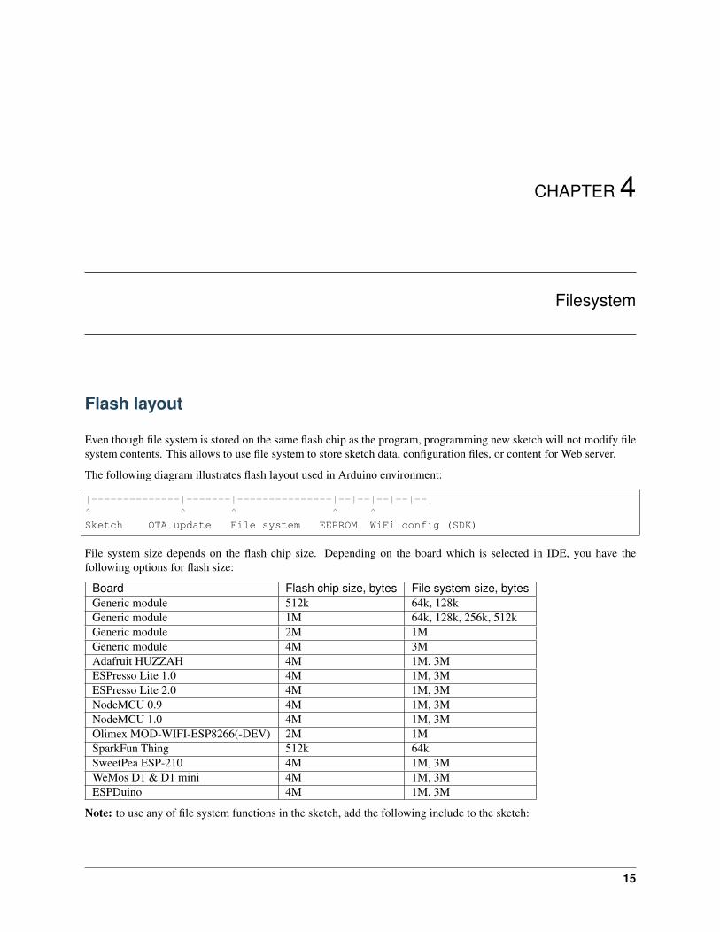
The following diagram illustrates flash layout used in Arduino environment:
|--------------|-------|---------------|--|--|--|--|--|^ ^ ^ ^ ^Sketch OTA update File system EEPROM WiFi config (SDK)
File system size depends on the flash chip size. Depending on the board which is selected in IDE, you have thefollowing options for flash size:
Board Flash chip size, bytes File system size, bytesGeneric module 512k 64k, 128kGeneric module 1M 64k, 128k, 256k, 512kGeneric module 2M 1MGeneric module 4M 3MAdafruit HUZZAH 4M 1M, 3MESPresso Lite 1.0 4M 1M, 3MESPresso Lite 2.0 4M 1M, 3MNodeMCU 0.9 4M 1M, 3MNodeMCU 1.0 4M 1M, 3MOlimex MOD-WIFI-ESP8266(-DEV) 2M 1MSparkFun Thing 512k 64kSweetPea ESP-210 4M 1M, 3MWeMos D1 & D1 mini 4M 1M, 3MESPDuino 4M 1M, 3M
Note: to use any of file system functions in the sketch, add the following include to the sketch:
15
ESP8266 Arduino Core Documentation, Release 2.4.0
#include "FS.h"
File system limitations
The filesystem implementation for ESP8266 had to accomodate the constraints of the chip, among which its limitedRAM. SPIFFS was selected because it is designed for small systems, but that comes at the cost of some simplificationsand limitations.
First, behind the scenes, SPIFFS does not support directories, it just stores a “flat” list of files. But contrary totraditional filesystems, the slash character '/' is allowed in filenames, so the functions that deal with directory listing(e.g. openDir("/website")) basically just filter the filenames and keep the ones that start with the requestedprefix (/website/). Practically speaking, that makes little difference though.
Second, there is a limit of 32 chars in total for filenames. One '\0' char is reserved for C string termination, so thatleaves us with 31 usable characters.
Combined, that means it is advised to keep filenames short and not use deeply nested directories, as the full path ofeach file (including directories, '/' characters, base name, dot and extension) has to be 31 chars at a maximum. Forexample, the filename /website/images/bird_thumbnail.jpg is 34 chars and will cause some problems ifused, for example in exists() or in case another file starts with the same first 31 characters.
Warning: That limit is easily reached and if ignored, problems might go unnoticed because no error message willappear at compilation nor runtime.
For more details on the internals of SPIFFS implementation, see the SPIFFS readme file.
Uploading files to file system
ESP8266FS is a tool which integrates into the Arduino IDE. It adds a menu item to Tools menu for uploading thecontents of sketch data directory into ESP8266 flash file system.
• Download the tool: https://github.com/esp8266/arduino-esp8266fs-plugin/releases/download/0.3.0/ESP8266FS-0.3.0.zip.
• In your Arduino sketchbook directory, create tools directory if it doesn’t exist yet
• Unpack the tool into tools directory (the path will look like <home_dir>/Arduino/tools/ESP8266FS/tool/esp8266fs.jar)
• Restart Arduino IDE
• Open a sketch (or create a new one and save it)
• Go to sketch directory (choose Sketch > Show Sketch Folder)
• Create a directory named data and any files you want in the file system there
• Make sure you have selected a board, port, and closed Serial Monitor
• Select Tools > ESP8266 Sketch Data Upload. This should start uploading the files into ESP8266 flash filesystem. When done, IDE status bar will display SPIFFS Image Uploaded message.
16 Chapter 4. Filesystem
ESP8266 Arduino Core Documentation, Release 2.4.0
File system object (SPIFFS)
begin
SPIFFS.begin()
This method mounts SPIFFS file system. It must be called before any other FS APIs are used. Returns true if filesystem was mounted successfully, false otherwise.
end
SPIFFS.end()
This method unmounts SPIFFS file system. Use this method before updating SPIFFS using OTA.
format
SPIFFS.format()
Formats the file system. May be called either before or after calling begin. Returns true if formatting was successful.
open
SPIFFS.open(path, mode)
Opens a file. path should be an absolute path starting with a slash (e.g. /dir/filename.txt). mode is a stringspecifying access mode. It can be one of “r”, “w”, “a”, “r+”, “w+”, “a+”. Meaning of these modes is the same as forfopen C function.
r Open text file for reading. The stream is positioned at thebeginning of the file.
r+ Open for reading and writing. The stream is positioned at thebeginning of the file.
w Truncate file to zero length or create text file for writing.The stream is positioned at the beginning of the file.
w+ Open for reading and writing. The file is created if it doesnot exist, otherwise it is truncated. The stream ispositioned at the beginning of the file.
a Open for appending (writing at end of file). The file iscreated if it does not exist. The stream is positioned at theend of the file.
a+ Open for reading and appending (writing at end of file). Thefile is created if it does not exist. The initial fileposition for reading is at the beginning of the file, butoutput is always appended to the end of the file.
4.4. File system object (SPIFFS) 17

ESP8266 Arduino Core Documentation, Release 2.4.0
Returns File object. To check whether the file was opened successfully, use the boolean operator.
File f = SPIFFS.open("/f.txt", "w");if (!f) {
Serial.println("file open failed");}
exists
SPIFFS.exists(path)
Returns true if a file with given path exists, false otherwise.
openDir
SPIFFS.openDir(path)
Opens a directory given its absolute path. Returns a Dir object.
remove
SPIFFS.remove(path)
Deletes the file given its absolute path. Returns true if file was deleted successfully.
rename
SPIFFS.rename(pathFrom, pathTo)
Renames file from pathFrom to pathTo. Paths must be absolute. Returns true if file was renamed successfully.
info
FSInfo fs_info;SPIFFS.info(fs_info);
Fills FSInfo structure with information about the file system. Returns true is successful, false otherwise.
Filesystem information structure
struct FSInfo {size_t totalBytes;size_t usedBytes;size_t blockSize;size_t pageSize;size_t maxOpenFiles;size_t maxPathLength;
};
18 Chapter 4. Filesystem

ESP8266 Arduino Core Documentation, Release 2.4.0
This is the structure which may be filled using FS::info method. - totalBytes — total size of useful data on the filesystem - usedBytes — number of bytes used by files - blockSize — SPIFFS block size - pageSize — SPIFFSlogical page size - maxOpenFiles — max number of files which may be open simultaneously - maxPathLength— max file name length (including one byte for zero termination)
Directory object (Dir)
The purpose of Dir object is to iterate over files inside a directory. It provides three methods: next(), fileName(),and openFile(mode).
The following example shows how it should be used:
Dir dir = SPIFFS.openDir("/data");while (dir.next()) {
Serial.print(dir.fileName());File f = dir.openFile("r");Serial.println(f.size());
}
dir.next() returns true while there are files in the directory to iterate over. It must be called before callingfileName and openFile functions.
openFile method takes mode argument which has the same meaning as for SPIFFS.open function.
File object
SPIFFS.open and dir.openFile functions return a File object. This object supports all the functions of Stream,so you can use readBytes, findUntil, parseInt, println, and all other Stream methods.
There are also some functions which are specific to File object.
seek
file.seek(offset, mode)
This function behaves like fseek C function. Depending on the value of mode, it moves current position in a file asfollows:
• if mode is SeekSet, position is set to offset bytes from the beginning.
• if mode is SeekCur, current position is moved by offset bytes.
• if mode is SeekEnd, position is set to offset bytes from the end of the file.
Returns true if position was set successfully.
position
file.position()
Returns the current position inside the file, in bytes.
4.6. Directory object (Dir) 19

ESP8266 Arduino Core Documentation, Release 2.4.0
size
file.size()
Returns file size, in bytes.
name
String name = file.name();
Returns file name, as const char*. Convert it to String for storage.
close
file.close()
Close the file. No other operations should be performed on File object after close function was called.
20 Chapter 4. Filesystem
CHAPTER 5
ESP8266WiFi library
ESP8266 is all about Wi-Fi. If you are eager to connect your new ESP8266 module to Wi-Fi network to start sendingand receiving data, this is a good place to start. If you are looking for more in depth details of how to program specificWi-Fi networking functionality, you are also in the right place.
Introduction
The Wi-Fi library for ESP8266 has been developed basing on ESP8266 SDK, using naming convention and overallfunctionality philosophy of Arduino WiFi library. Over time the wealth Wi-Fi features ported from ESP9266 SDK toesp8266 / Adruino outgrow Arduino WiFi library and it became apparent that we need to provide separate documen-tation on what is new and extra.
This documentation will walk you through several classes, methods and properties of ESP8266WiFi library. If you arenew to C++ and Arduino, don’t worry. We will start from general concepts and then move to detailed description ofmembers of each particular class including usage examples.
The scope of functionality offered by ESP8266WiFi library is quite extensive and therefore this description has beenbroken up into separate documents marked with :arrow_right:.
Quick Start
Hopefully you are already familiar how to load Blink.ino sketch to ESP8266 module and get the LED blinking. If not,please check this tutorial by Adafruit or another great tutorial developed by Sparkfun.
To hook up ESP module to Wi-Fi (like hooking up a mobile phone to a hot spot), you need just couple of lines of code:
#include <ESP8266WiFi.h>
void setup(){
Serial.begin(115200);Serial.println();
21
ESP8266 Arduino Core Documentation, Release 2.4.0
WiFi.begin("network-name", "pass-to-network");
Serial.print("Connecting");while (WiFi.status() != WL_CONNECTED){delay(500);Serial.print(".");
}Serial.println();
Serial.print("Connected, IP address: ");Serial.println(WiFi.localIP());
}
void loop() {}
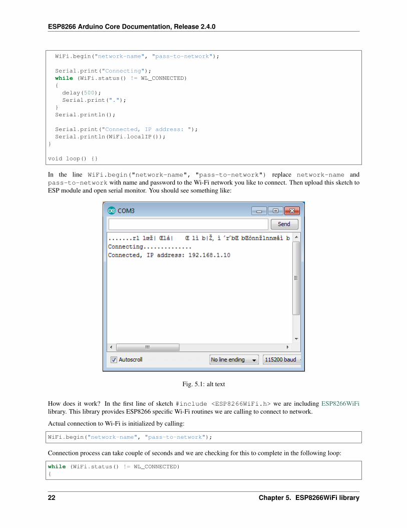
In the line WiFi.begin("network-name", "pass-to-network") replace network-name andpass-to-network with name and password to the Wi-Fi network you like to connect. Then upload this sketch toESP module and open serial monitor. You should see something like:
Fig. 5.1: alt text
How does it work? In the first line of sketch #include <ESP8266WiFi.h> we are including ESP8266WiFilibrary. This library provides ESP8266 specific Wi-Fi routines we are calling to connect to network.
Actual connection to Wi-Fi is initialized by calling:
WiFi.begin("network-name", "pass-to-network");
Connection process can take couple of seconds and we are checking for this to complete in the following loop:
while (WiFi.status() != WL_CONNECTED){
22 Chapter 5. ESP8266WiFi library

ESP8266 Arduino Core Documentation, Release 2.4.0
delay(500);Serial.print(".");
}
The while() loop will keep looping while WiFi.status() is other than WL_CONNECTED. The loop will exitonly if the status changes to WL_CONNECTED.
The last line will then print out IP address assigned to ESP module by DHCP:
Serial.println(WiFi.localIP());
If you don’t see the last line but just more and more dots ........., then likely name or password to the Wi-Finetwork in sketch is entered incorrectly. Verify name and password by connecting from scratch to this Wi-Fi a PC ora mobile phone.
Note: if connection is established, and then lost for some reason, ESP will automatically reconnect to last used accesspoint once it is again back on-line. This will be done automatically by Wi-Fi library, without any user intervention.
That’s all you need to connect ESP8266 to Wi-Fi. In the following chapters we will explain what cool things can bedone by ESP once connected.
Who is Who
Devices that connect to Wi-Fi network are called stations (STA). Connection to Wi-Fi is provided by an access point(AP), that acts as a hub for one or more stations. The access point on the other end is connected to a wired network. Anaccess point is usually integrated with a router to provide access from Wi-Fi network to the internet. Each access pointis recognized by a SSID (Service Set IDentifier), that essentially is the name of network you select when connectinga device (station) to the Wi-Fi.
ESP8266 module can operate as a station, so we can connect it to the Wi-Fi network. It can also operate as a softaccess point (soft-AP), to establish its own Wi-Fi network. Therefore we can connect other stations to such ESPmodule. ESP8266 is also able to operate both in station and soft access point mode. This provides possibility ofbuilding e.g. mesh networks.
Fig. 5.2: alt text
5.1. Introduction 23

ESP8266 Arduino Core Documentation, Release 2.4.0
The ESP8266WiFi library provides wide collection of C++ methods (functions) and properties to configure and operatean ESP8266 module in station and / or soft access point mode. They are described in the following chapters.
Class Description
The ESP8266WiFi library is broken up into several classes. In most of cases, when writing the code, user is notconcerned with this classification. We are using it to break up description of this library into more manageable pieces.
Fig. 5.3: alt text
Chapters below describe all function calls (methods and properties in C++ terms) listed in particular classes ofESP8266WiFi. Description is illustrated with application examples and code snippets to show how to use functions inpractice. Most of this information is broken up into separate documents. Please follow to access them.
Station
Station (STA) mode is used to get ESP module connected to a Wi-Fi network established by an access point.
Fig. 5.4: alt text
24 Chapter 5. ESP8266WiFi library

ESP8266 Arduino Core Documentation, Release 2.4.0
Station class has several features to facilitate management of Wi-Fi connection. In case the connection is lost, ESP8266will automatically reconnect to the last used access point, once it is again available. The same happens on modulereboot. This is possible since ESP is saving credentials to last used access point in flash (non-volatile) memory.Using the saved data ESP will also reconnect if sketch has been changed but code does not alter the Wi-Fi mode orcredentials.
Station Class documentation
Check out separate section with examples.
Soft Access Point
An access point (AP) is a device that provides access to Wi-Fi network to other devices (stations) and connects themfurther to a wired network. ESP8266 can provide similar functionality except it does not have interface to a wirednetwork. Such mode of operation is called soft access point (soft-AP). The maximum number of stations connected tothe soft-AP is five.
Fig. 5.5: alt text
The soft-AP mode is often used and an intermediate step before connecting ESP to a Wi-Fi in a station mode. This iswhen SSID and password to such network is not known upfront. ESP first boots in soft-AP mode, so we can connectto it using a laptop or a mobile phone. Then we are able to provide credentials to the target network. Once done ESPis switched to the station mode and can connect to the target Wi-Fi.
Another handy application of soft-AP mode is to set up mesh networks. ESP can operate in both soft-AP and Stationmode so it can act as a node of a mesh network.
Soft Access Point Class documentation
Check out separate section with examples.
Scan
To connect a mobile phone to a hot spot, you typically open Wi-Fi settings app, list available networks and pick thehot spot you need. Then enter a password (or not) and you are in. You can do the same with ESP. Functionality ofscanning for, and listing of available networks in range is implemented by the Scan Class.
Scan Class documentation.
5.2. Class Description 25

ESP8266 Arduino Core Documentation, Release 2.4.0
Check out separate section with examples.
Client
The Client class creates clients that can access services provided by servers in order to send, receive and process data.
Fig. 5.6: alt text
Check out separate section with examples / list of functions
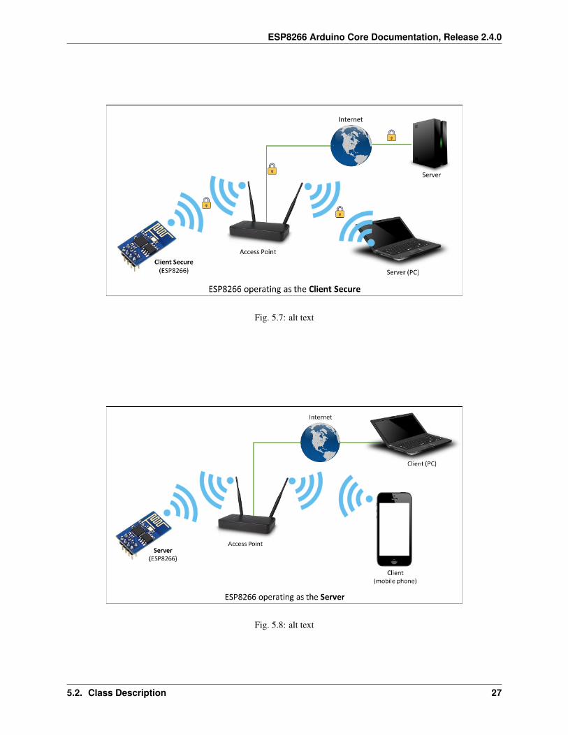
Client Secure
The Client Secure is an extension of Client Class where connection and data exchange with servers is done using asecure protocol. It supports TLS 1.1. The TLS 1.2 is not supported.
Secure applications have additional memory (and processing) overhead due to the need to run cryptography algorithms.The stronger the certificate’s key, the more overhead is needed. In practice it is not possible to run more than a singlesecure client at a time. The problem concerns RAM memory we can not add, the flash memory size is usually not theissue. If you like to learn how client secure library has been developed, access to what servers have been tested, andhow memory limitations have been overcame, read fascinating issue report #43.
Check out separate section with examples / list of functions
Server
The Server Class creates servers that provide functionality to other programs or devices, called clients.
Clients connect to sever to send and receive data and access provided functionality.
Check out separate section with examples / list of functions.
26 Chapter 5. ESP8266WiFi library
ESP8266 Arduino Core Documentation, Release 2.4.0
Fig. 5.7: alt text
Fig. 5.8: alt text
5.2. Class Description 27
ESP8266 Arduino Core Documentation, Release 2.4.0
UDP
The UDP Class enables the User Datagram Protocol (UDP) messages to be sent and received. The UDP uses a simple“fire and forget” transmission model with no guarantee of delivery, ordering, or duplicate protection. UDP provideschecksums for data integrity, and port numbers for addressing different functions at the source and destination of thedatagram.
Check out separate section with examples / list of functions.
Generic
There are several functions offered by ESP8266’s SDK and not present in Arduino WiFi library. If such functiondoes not fit into one of classes discussed above, it will likely be in Generic Class. Among them is handler to manageWi-Fi events like connection, disconnection or obtaining an IP, Wi-Fi mode changes, functions to manage modulesleep mode, hostname to an IP address resolution, etc.
Check out separate section with examples / list of functions.
Diagnostics
There are several techniques available to diagnose and troubleshoot issues with getting connected to Wi-Fi and keepingconnection alive.
Check Return Codes
Almost each function described in chapters above returns some diagnostic information.
Such diagnostic may be provided as a simple boolean type true' orfalse‘ to indicate operation result. You maycheck this result as described in examples, for instance:
Serial.printf("Wi-Fi mode set to WIFI_STA %s\n", WiFi.mode(WIFI_STA) ? "" : "Failed!→˓");
Some functions provide more than just a binary status information. A good example is WiFi.status().
Serial.printf("Connection status: %d\n", WiFi.status());
This function returns following codes to describe what is going on with Wi-Fi connection: * 0 : WL_IDLE_STATUSwhen Wi-Fi is in process of changing between statuses * 1 : WL_NO_SSID_AVAILin case configured SSID cannot bereached * 3 : WL_CONNECTED after successful connection is established * 4 : WL_CONNECT_FAILED if passwordis incorrect * 6 : WL_DISCONNECTED if module is not configured in station mode
It is a good practice to display and check information returned by functions. Application development and trou-bleshooting will be easier with that.
Use printDiag
There is a specific function available to print out key Wi-Fi diagnostic information:
WiFi.printDiag(Serial);
A sample output of this function looks as follows:
28 Chapter 5. ESP8266WiFi library

ESP8266 Arduino Core Documentation, Release 2.4.0
Mode: STA+APPHY mode: NChannel: 11AP id: 0Status: 5Auto connect: 1SSID (10): sensor-netPassphrase (12): 123!$#0&*esPBSSID set: 0
Use this function to provide snapshot of Wi-Fi status in these parts of application code, that you suspect may be failing.
Enable Wi-Fi Diagnostic
By default the diagnostic output from Wi-Fi libraries is disabled when you call Serial.begin. To enable de-bug output again, call Serial.setDebugOutput(true). To redirect debug output to Serial1 instead, callSerial1.setDebugOutput(true). For additional details regarding diagnostics using serial ports please referto the documentation.
Below is an example of output for sample sketch discussed in Quick Start above with Serial.setDebugOutput(true):
Connectingscandonestate: 0 -> 2 (b0)state: 2 -> 3 (0)state: 3 -> 5 (10)add 0aid 1cnt
connected with sensor-net, channel 6dhcp client start...chg_B1:-40...ip:192.168.1.10,mask:255.255.255.0,gw:192.168.1.9.Connected, IP address: 192.168.1.10
The same sketch without Serial.setDebugOutput(true) will print out only the following:
Connecting....Connected, IP address: 192.168.1.10
Enable Debugging in IDE
Arduino IDE provides convenient method to enable debugging for specific libraries.
What’s Inside?
If you like to analyze in detail what is inside of the ESP8266WiFi library, go directly to the ESP8266WiFi folder ofesp8266 / Arduino repository on the GitHub.
5.4. What’s Inside? 29

ESP8266 Arduino Core Documentation, Release 2.4.0
To make the analysis easier, rather than looking into individual header or source files, use one of free tools to automat-ically generate documentation. The class index in chapter Class Description above has been prepared in no time usinggreat Doxygen, that is the de facto standard tool for generating documentation from annotated C++ sources.
Fig. 5.9: alt text
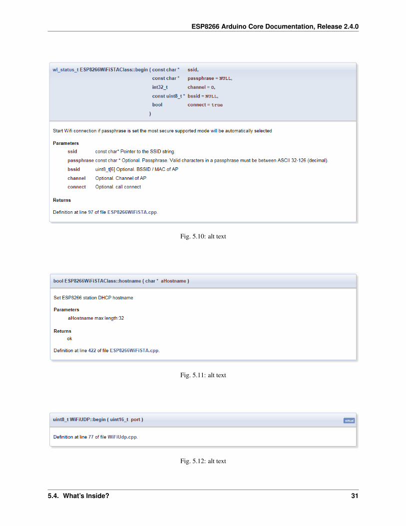
The tool crawls through all header and source files collecting information from formatted comment blocks. If devel-oper of particular class annotated the code, you will see it like in examples below.
If code is not annotated, you will still see the function prototype including types of arguments, and can use providedlinks to jump straight to the source code to check it out on your own. Doxygen provides really excellent navigationbetween members of library.
Several classes of ESP8266WiFi are not annotated. When preparing this document, Doxygen has been tremendoushelp to quickly navigate through almost 30 files that make this library.
30 Chapter 5. ESP8266WiFi library
ESP8266 Arduino Core Documentation, Release 2.4.0
Fig. 5.10: alt text
Fig. 5.11: alt text
Fig. 5.12: alt text
5.4. What’s Inside? 31

ESP8266 Arduino Core Documentation, Release 2.4.0
32 Chapter 5. ESP8266WiFi library

CHAPTER 6
OTA Updates
Introduction
OTA (Over the Air) update is the process of loading the firmware to ESP module using Wi-Fi connection rather thana serial port. Such functionality became extremely useful in case of limited or no physical access to the module.
OTA may be done using:
• Arduino IDE
• Web Browser
• HTTP Server
Arduino IDE option is intended primarily for software development phase. The two other options would be moreuseful after deployment, to provide module with application updates manually with a web browser, or automaticallyusing a http server.
In any case, the first firmware upload has to be done over a serial port. If the OTA routines are correctly implementedin a sketch, then all subsequent uploads may be done over the air.
There is no imposed security on OTA process from being hacked. It is up to developer to ensure that updates areallowed only from legitimate / trusted sources. Once the update is complete, the module restarts, and the new code isexecuted. The developer should ensure that the application running on the module is shut down and restarted in a safemanner. Chapters below provide additional information regarding security and safety of OTA process.
Security
Module has to be exposed wirelessly to get it updated with a new sketch. That poses chances of module being violentlyhacked and loaded with some other code. To reduce likelihood of being hacked consider protecting your uploads witha password, selecting certain OTA port, etc.
Check functionality provided with ArduinoOTA library that may improve security:
33

ESP8266 Arduino Core Documentation, Release 2.4.0
void setPort(uint16_t port);void setHostname(const char* hostname);void setPassword(const char* password);
Certain protection functionality is already built in and do not require any additional coding by developer. ArduinoOTAand espota.py use Digest-MD5 to authenticate upload. Integrity of transferred data is verified on ESP side using MD5checksum.
Make your own risk analysis and depending on application decide what library functions to implement. If required,consider implementation of other means of protection from being hacked, e.g. exposing module for uploads onlyaccording to specific schedule, trigger OTA only be user pressing dedicated “Update” button wired to ESP, etc.
Safety
OTA process takes ESP’s resources and bandwidth during upload. Then module is restarted and a new sketch executed.Analyse and test how it affects functionality of existing and new sketch.
If ESP is placed in remote location and controlling some equipment, you should put additional attention what happensif operation of this equipment is suddenly interrupted by update process. Therefore, decide how to put this equipmentinto safe state before starting the update. For instance, your module may be controlling a garden watering system in asequence. If this sequence is not properly shut down and a water valve left open, your garden may be flooded.
The following functions are provided with ArduinoOTA library and intended to handle functionality of your applica-tion during specific stages of OTA, or on an OTA error:
void onStart(OTA_CALLBACK(fn));void onEnd(OTA_CALLBACK(fn));void onProgress(OTA_CALLBACK_PROGRESS(fn));void onError(OTA_CALLBACK_ERROR (fn));
Basic Requirements
Flash chip size should be able to hold the old sketch (currently running) and the new sketch (OTA) at the same time.
Keep in mind that the File system and EEPROM for example needs space too (one time) see flash layout.
ESP.getFreeSketchSpace();
can be used for checking the free space for the new sketch.
For overview of memory layout, where new sketch is stored and how it is copied during OTA process, see Updateprocess - memory view.
The following chapters provide more details and specific methods of doing OTA.
Arduino IDE
Uploading modules wirelessly from Arduino IDE is intended for the following typical scenarios: - during firmwaredevelopment as a quicker alternative to loading over a serial, - for updating small quantity of modules, - only if modulesare available on the same network as the computer with Arduino IDE.
34 Chapter 6. OTA Updates
ESP8266 Arduino Core Documentation, Release 2.4.0
Requirements
• The ESP and the computer must be connected to the same network.
Application Example
Instructions below show configuration of OTA on NodeMCU 1.0 (ESP-12E Module) board. You can use any otherboard assuming that it meets requirements described above. This instruction is valid for all operating systems sup-ported by Arduino IDE. Screen captures have been made on Windows 7 and you may see small differences (like nameof serial port), if you are using Linux and MacOS.
1. Before you begin, please make sure that you have the following s/w installed:
• Arduino IDE 1.6.7 or newer - https://www.arduino.cc/en/Main/Software
• esp8266/Arduino platform package 2.0.0 or newer - for instructions follow https://github.com/esp8266/Arduino#installing-with-boards-manager
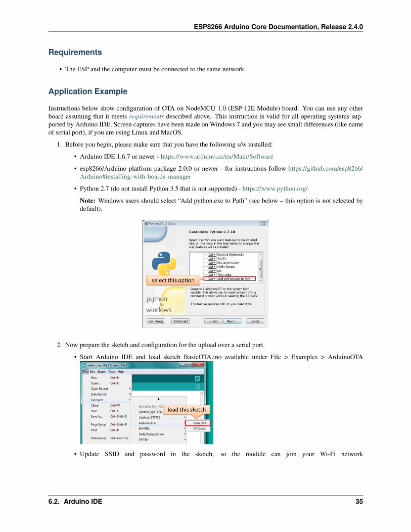
• Python 2.7 (do not install Python 3.5 that is not supported) - https://www.python.org/
Note: Windows users should select “Add python.exe to Path” (see below – this option is not selected bydefault).
2. Now prepare the sketch and configuration for the upload over a serial port.
• Start Arduino IDE and load sketch BasicOTA.ino available under File > Examples > ArduinoOTA
• Update SSID and password in the sketch, so the module can join your Wi-Fi network
6.2. Arduino IDE 35

ESP8266 Arduino Core Documentation, Release 2.4.0
• Configure upload parameters as below (you may need to adjust configuration if you are using a different
module):
Note: Depending on version of platform package and board you have, you may see Upload Using:in the menu above. This option is inactive and it does not matter what you select. It has been left forcompatibility with older implementation of OTA and finally removed in platform package version 2.2.0.
3. Upload the sketch (Ctrl+U). Once done, open Serial Monitor (Ctrl+Shift+M) and check if module has joinedyour Wi-Fi network:
Note: ESP module should be reset after serial upload. Otherwise subsequent steps will not work. Reset may be doneautomatically for you after opening serial monitor as visible on the screenshot above. It depends on how you haveDTR and RTS wired from USB-Serial converter to the ESP. If reset is not done automatically, then do it by pressingreset button or manually cycling the power. For more details why this should be done please refer to FAQ regardingESP.restart().
4. Only if module is connected to network, after a couple of seconds, the esp8266-ota port will show up in ArduinoIDE. Select port with IP address shown in the Serial Monitor window in previous step:
Note: If OTA port does not show up, exit Arduino IDE, open it again and check if port is there. If it does nothelp, check your firewall and router settings. OTA port is advertised using mDNS service. To check if port isvisible by your PC, you can use application like Bonjour Browser.
5. Now get ready for your first OTA upload by selecting the OTA port:
36 Chapter 6. OTA Updates

ESP8266 Arduino Core Documentation, Release 2.4.0
6.2. Arduino IDE 37

ESP8266 Arduino Core Documentation, Release 2.4.0
Note: The menu entry Upload Speed: does not matter at this point as it concerns the serial port. Just left itunchanged.
6. If you have successfully completed all the above steps, you can upload (Ctrl+U) the same (or any other) sketchover OTA:
Note: To be able to upload your sketch over and over again using OTA, you need to embed OTA routines inside.Please use BasicOTA.ino as an example.
Password Protection
Protecting your OTA uploads with password is really straightforward. All you need to do, is to include the followingstatement in your code:
ArduinoOTA.setPassword((const char *)"123");
Where 123 is a sample password that you should replace with your own.
Before implementing it in your sketch, it is a good idea to check how it works using BasicOTA.ino sketch availableunder File > Examples > ArduinoOTA. Go ahead, open BasicOTA.ino, uncomment the above statement that is alreadythere, and upload the sketch. To make troubleshooting easier, do not modify example sketch besides what is absolutelyrequired. This is including original simple 123 OTA password. Then attempt to upload sketch again (using OTA).After compilation is complete, once upload is about to begin, you should see prompt for password as follows:
Enter the password and upload should be initiated as usual with the only difference being Authenticating...OKmessage visible in upload log.
You will not be prompted for a reentering the same password next time. Arduino IDE will remember it for you. Youwill see prompt for password only after reopening IDE, or if you change it in your sketch, upload the sketch and thentry to upload it again.
Please note, it is possible to reveal password entered previously in Arduino IDE, if IDE has not been closed since lastupload. This can be done by enabling Show verbose output during: upload in File > Preferences and attempting toupload the module.
The picture above shows that the password is visible in log, as it is passed to espota.py upload script.
Another example below shows situation when password is changed between uploads.
When uploading, Arduino IDE used previously entered password, so the upload failed and that has been clearlyreported by IDE. Only then IDE prompted for a new password. That was entered correctly and second attempt toupload has been successful.
38 Chapter 6. OTA Updates

ESP8266 Arduino Core Documentation, Release 2.4.0
6.2. Arduino IDE 39

ESP8266 Arduino Core Documentation, Release 2.4.0
Troubleshooting
If OTA update fails, first step is to check for error messages that may be shown in upload window of Arduino IDE. Ifthis is not providing any useful hints, try to upload again while checking what is shown by ESP on serial port. SerialMonitor from IDE will not be useful in that case. When attempting to open it, you will likely see the following:
This window is for Arduino Yún and not yet implemented for esp8266/Arduino. It shows up because IDE is attemptingto open Serial Monitor using network port you have selected for OTA upload.
Instead you need an external serial monitor. If you are a Windows user check out Termite. This is handy, slick andsimple RS232 terminal that does not impose RTS or DTR flow control. Such flow control may cause issues if you areusing respective lines to toggle GPIO0 and RESET pins on ESP for upload.
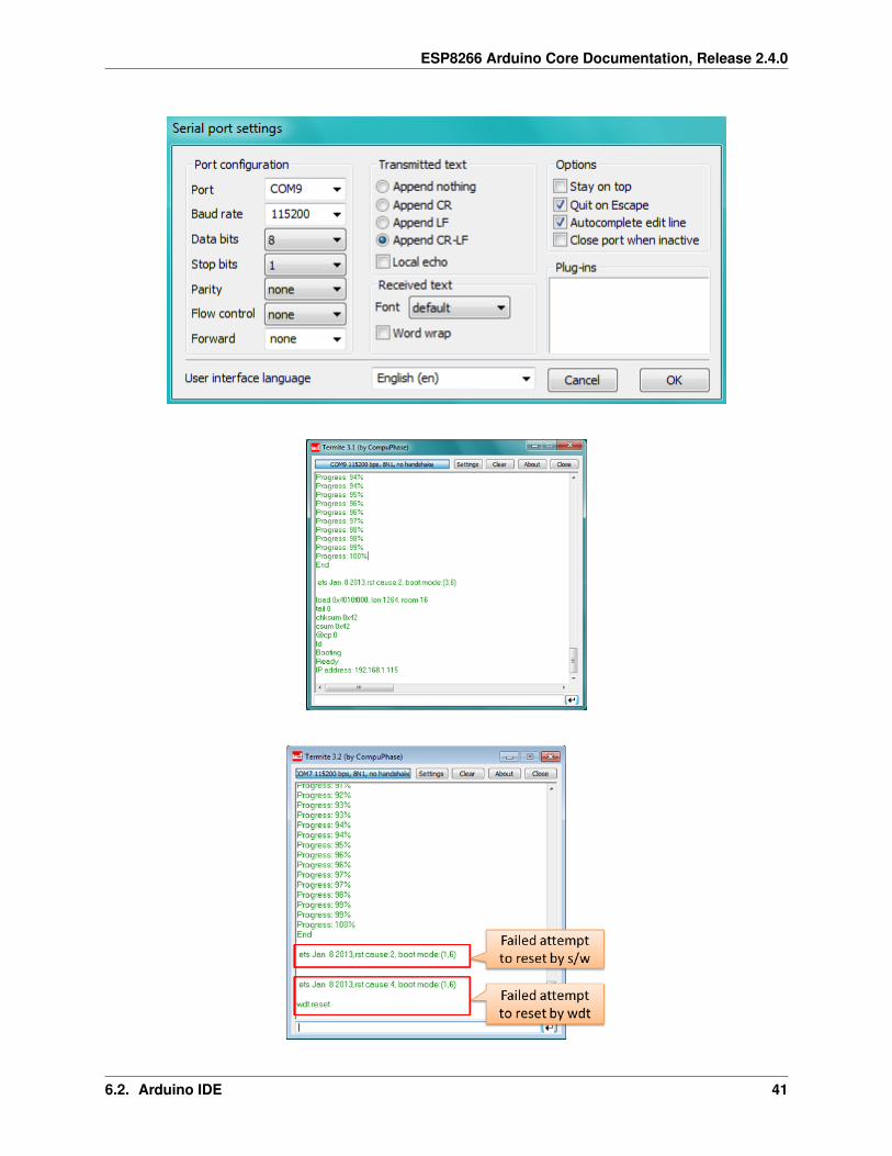
Select COM port and baud rate on external terminal program as if you were using Arduino Serial Monitor. Please seetypical settings for Termite below:
Then run OTA from IDE and look what is displayed on terminal. Successful ArduinoOTA process using BasicOTA.inosketch looks like below (IP address depends on your network configuration):
If upload fails you will likely see errors caught by the uploader, exception and the stack trace, or both.
Instead of the log as on the above screen you may see the following:
If this is the case, then most likely ESP module has not been reset after initial upload using serial port.
The most common causes of OTA failure are as follows: * not enough physical memory on the chip (e.g. ESP01with 512K flash memory is not enough for OTA), * too much memory declared for SPIFFS so new sketch will not fitbetween existing sketch and SPIFFS – see Update process - memory view, * too little memory declared in ArduinoIDE for your selected board (i.e. less than physical size), * not resetting the ESP module after initial upload usingserial port.
40 Chapter 6. OTA Updates
ESP8266 Arduino Core Documentation, Release 2.4.0
6.2. Arduino IDE 41

ESP8266 Arduino Core Documentation, Release 2.4.0
For more details regarding flash memory layout please check File system. For overview where new sketch is stored,how it is copied and how memory is organized for the purpose of OTA see Update process - memory view.
Web Browser
Updates described in this chapter are done with a web browser that can be useful in the following typical scenarios:
• after application deployment if loading directly from Arduino IDE is inconvenient or not possible,
• after deployment if user is unable to expose module for OTA from external update server,
• to provide updates after deployment to small quantity of modules when setting an update server is not practica-ble.
Requirements
• The ESP and the computer must be connected to the same network.
Implementation Overview
Updates with a web browser are implemented using ESP8266HTTPUpdateServer class together withESP8266WebServer and ESP8266mDNS classes. The following code is required to get it work:
setup()
MDNS.begin(host);
httpUpdater.setup(&httpServer);httpServer.begin();
MDNS.addService("http", "tcp", 80);
loop()
httpServer.handleClient();
Application Example
The sample implementation provided below has been done using:
• example sketch WebUpdater.ino available in ESP8266HTTPUpdateServer library,
• NodeMCU 1.0 (ESP-12E Module).
You can use another module if it meets previously described requirements.
1. Before you begin, please make sure that you have the following software installed:
• Arduino IDE and 2.0.0-rc1 (of Nov 17, 2015) version of platform package as described under https://github.com/esp8266/Arduino#installing-with-boards-manager
• Host software depending on O/S you use:
(a) Avahi http://avahi.org/ for Linux
(b) Bonjour http://www.apple.com/support/bonjour/ for Windows
42 Chapter 6. OTA Updates

ESP8266 Arduino Core Documentation, Release 2.4.0
(c) Mac OSX and iOS - support is already built in / no any extra s/w is required
2. Prepare the sketch and configuration for initial upload with a serial port.
• Start Arduino IDE and load sketch WebUpdater.ino available under File > Examples >ESP8266HTTPUpdateServer.
• Update SSID and password in the sketch, so the module can join your Wi-Fi network.
• Open File > Preferences, look for “Show verbose output during:” and check out “compilation” option.
Note: This setting will be required in step 5 below. You can uncheck this setting afterwards.
3. Upload sketch (Ctrl+U). Once done, open Serial Monitor (Ctrl+Shift+M) and check if you see the followingmessage displayed, that contains url for OTA update.
Note: Such message will be shown only after module successfully joins network and is ready for an OTAupload. Please remember about resetting the module once after serial upload as discussed in chapter ArduinoIDE, step 3.
4. Now open web browser and enter the url provided on Serial Monitor, i.e. http://esp8266-webupdate.local/update. Once entered, browser should display a form like below that has been served by your module.The form invites you to choose a file for update.
Note: If entering http://esp8266-webupdate.local/update does not work, try replacingesp8266-webupdate with module’s IP address. For example, if your module IP is 192.168.1.100then url should be http://192.168.1.100/update. This workaround is useful in case the host softwareinstalled in step 1 does not work. If still nothing works and there are no clues on the Serial Monitor, try todiagnose issue by opening provided url in Google Chrome, pressing F12 and checking contents of “Console”and “Network” tabs. Chrome provides some advanced logging on these tabs.
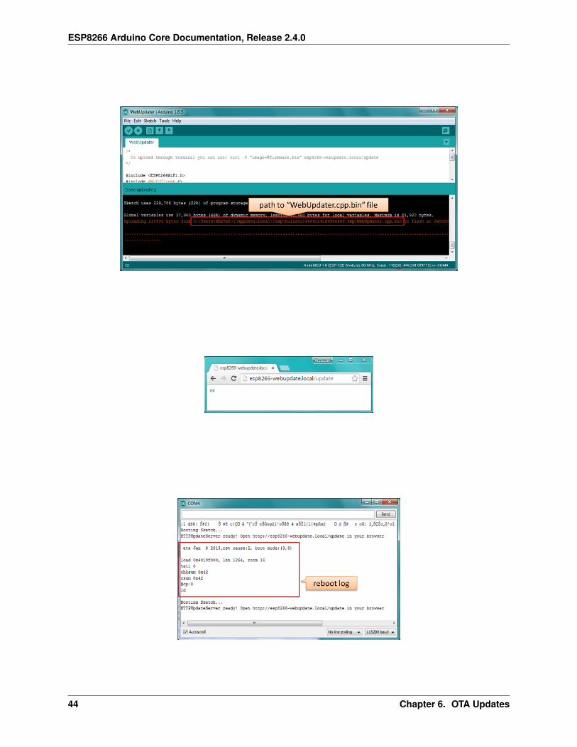
5. To obtain the file, navigate to directory used by Arduino IDE to store results of compilation. You can check thepath to this file in compilation log shown in IDE debug window as marked below.
6. Now press “Choose File” in web browser, go to directory identified in step 5 above, find the file “WebUp-dater.cpp.bin” and upload it. If upload is successful, you will see “OK” on web browser like below.
Module will reboot that should be visible on Serial Monitor:
6.3. Web Browser 43
ESP8266 Arduino Core Documentation, Release 2.4.0
44 Chapter 6. OTA Updates

ESP8266 Arduino Core Documentation, Release 2.4.0
Just after reboot you should see exactly the same message HTTPUpdateServer ready! Open http://esp8266-webupdate.local /update in your browser like in step 3. This is because modulehas been loaded again with the same code – first using serial port, and then using OTA.
Once you are comfortable with this procedure, go ahead and modify WebUpdater.ino sketch to print some additionalmessages, compile it, locate new binary file and upload it using web browser to see entered changes on a SerialMonitor.
You can also add OTA routines to your own sketch following guidelines in Implementation Overview above. If this isdone correctly, you should be always able to upload new sketch over the previous one using a web browser.
In case OTA update fails dead after entering modifications in your sketch, you can always recover module by loadingit over a serial port. Then diagnose the issue with sketch using Serial Monitor. Once the issue is fixed try OTA again.
HTTP Server
ESPhttpUpdate class can check for updates and download a binary file from HTTP web server. It is possible todownload updates from every IP or domain address on the network or Internet.
Requirements
• web server
Arduino code
Simple updater
Simple updater downloads the file every time the function is called.
ESPhttpUpdate.update("192.168.0.2", 80, "/arduino.bin");
Advanced updater
Its possible to point update function to a script at the server. If version string argument is given, it will be sent to theserver. Server side script can use this to check if update should be performed.
Server side script can respond as follows: - response code 200, and send the firmware image, - or response code 304to notify ESP that no update is required.
t_httpUpdate_return ret = ESPhttpUpdate.update("192.168.0.2", 80, "/esp/update/→˓arduino.php", "optional current version string here");switch(ret) {
case HTTP_UPDATE_FAILED:Serial.println("[update] Update failed.");break;
case HTTP_UPDATE_NO_UPDATES:Serial.println("[update] Update no Update.");break;
case HTTP_UPDATE_OK:Serial.println("[update] Update ok."); // may not called we reboot the ESPbreak;
}
6.4. HTTP Server 45

ESP8266 Arduino Core Documentation, Release 2.4.0
Server request handling
Simple updater
For the simple updater the server only needs to deliver the binary file for update.
Advanced updater
For advanced update management a script needs to run at the server side, for example a PHP script. At every updaterequest the ESP sends some information in HTTP headers to the server.
Example header data:
[HTTP_USER_AGENT] => ESP8266-http-Update[HTTP_X_ESP8266_STA_MAC] => 18:FE:AA:AA:AA:AA[HTTP_X_ESP8266_AP_MAC] => 1A:FE:AA:AA:AA:AA[HTTP_X_ESP8266_FREE_SPACE] => 671744[HTTP_X_ESP8266_SKETCH_SIZE] => 373940[HTTP_X_ESP8266_SKETCH_MD5] => a56f8ef78a0bebd812f62067daf1408a[HTTP_X_ESP8266_CHIP_SIZE] => 4194304[HTTP_X_ESP8266_SDK_VERSION] => 1.3.0[HTTP_X_ESP8266_VERSION] => DOOR-7-g14f53a19
With this information the script now can check if an update is needed. It is also possible to deliver different binariesbased on the MAC address for example.
Script example:
<?PHP
header('Content-type: text/plain; charset=utf8', true);
function check_header($name, $value = false) {if(!isset($_SERVER[$name])) {
return false;}if($value && $_SERVER[$name] != $value) {
return false;}return true;
}
function sendFile($path) {header($_SERVER["SERVER_PROTOCOL"].' 200 OK', true, 200);header('Content-Type: application/octet-stream', true);header('Content-Disposition: attachment; filename='.basename($path));header('Content-Length: '.filesize($path), true);header('x-MD5: '.md5_file($path), true);readfile($path);
}
if(!check_header('HTTP_USER_AGENT', 'ESP8266-http-Update')) {header($_SERVER["SERVER_PROTOCOL"].' 403 Forbidden', true, 403);echo "only for ESP8266 updater!\n";exit();
}
46 Chapter 6. OTA Updates
ESP8266 Arduino Core Documentation, Release 2.4.0
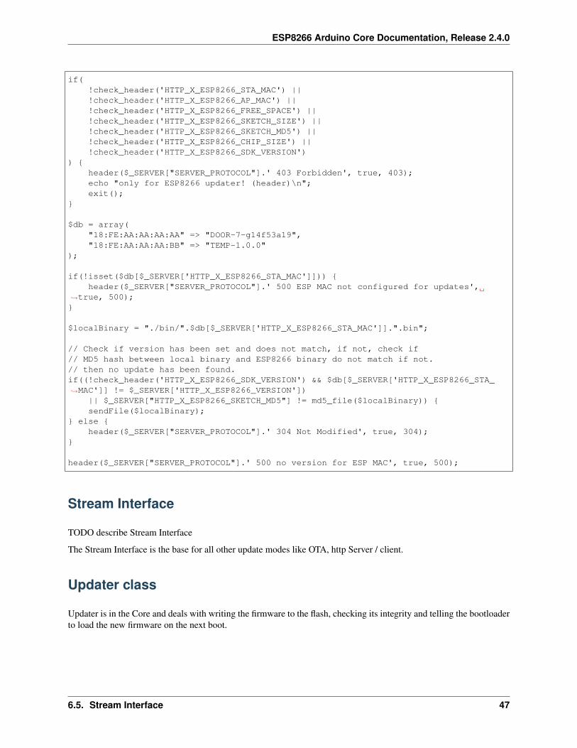
if(!check_header('HTTP_X_ESP8266_STA_MAC') ||!check_header('HTTP_X_ESP8266_AP_MAC') ||!check_header('HTTP_X_ESP8266_FREE_SPACE') ||!check_header('HTTP_X_ESP8266_SKETCH_SIZE') ||!check_header('HTTP_X_ESP8266_SKETCH_MD5') ||!check_header('HTTP_X_ESP8266_CHIP_SIZE') ||!check_header('HTTP_X_ESP8266_SDK_VERSION')
) {header($_SERVER["SERVER_PROTOCOL"].' 403 Forbidden', true, 403);echo "only for ESP8266 updater! (header)\n";exit();
}
$db = array("18:FE:AA:AA:AA:AA" => "DOOR-7-g14f53a19","18:FE:AA:AA:AA:BB" => "TEMP-1.0.0"
);
if(!isset($db[$_SERVER['HTTP_X_ESP8266_STA_MAC']])) {header($_SERVER["SERVER_PROTOCOL"].' 500 ESP MAC not configured for updates',
→˓true, 500);}
$localBinary = "./bin/".$db[$_SERVER['HTTP_X_ESP8266_STA_MAC']].".bin";
// Check if version has been set and does not match, if not, check if// MD5 hash between local binary and ESP8266 binary do not match if not.// then no update has been found.if((!check_header('HTTP_X_ESP8266_SDK_VERSION') && $db[$_SERVER['HTTP_X_ESP8266_STA_→˓MAC']] != $_SERVER['HTTP_X_ESP8266_VERSION'])
|| $_SERVER["HTTP_X_ESP8266_SKETCH_MD5"] != md5_file($localBinary)) {sendFile($localBinary);
} else {header($_SERVER["SERVER_PROTOCOL"].' 304 Not Modified', true, 304);
}
header($_SERVER["SERVER_PROTOCOL"].' 500 no version for ESP MAC', true, 500);
Stream Interface
TODO describe Stream Interface
The Stream Interface is the base for all other update modes like OTA, http Server / client.
Updater class
Updater is in the Core and deals with writing the firmware to the flash, checking its integrity and telling the bootloaderto load the new firmware on the next boot.
6.5. Stream Interface 47

ESP8266 Arduino Core Documentation, Release 2.4.0
Update process - memory view
• The new sketch will be stored in the space between the old sketch and the spiff.
• on the next reboot the “eboot” bootloader check for commands.
• the new sketch is now copied “over” the old one.
• the new sketch is started.
48 Chapter 6. OTA Updates

CHAPTER 7
Boards
Adafruit HUZZAH ESP8266 (ESP-12)
TODO: add notes
ESPresso Lite 1.0
ESPresso Lite 1.0 (beta version) is an Arduino-compatible Wi-Fi development board powered by Espressif System’sown ESP8266 WROOM-02 module. It has breadboard-friendly breakout pins with in-built LED, two reset/flashbuttons and a user programmable button . The operating voltage is 3.3VDC, regulated with 800mA maximum current.Special distinctive features include on-board I2C pads that allow direct connection to OLED LCD and sensor boards.
ESPresso Lite 2.0
ESPresso Lite 2.0 is an Arduino-compatible Wi-Fi development board based on an earlier V1 (beta version). Re-designed together with Cytron Technologies, the newly-revised ESPresso Lite V2.0 features the auto-load/auto-program function, eliminating the previous need to reset the board manually before flashing a new program. It alsofeature two user programmable side buttons and a reset button. The special distinctive features of on-board pads forI2C sensor and actuator is retained.
Phoenix 1.0
Product page: http://www.espert.co
49
ESP8266 Arduino Core Documentation, Release 2.4.0
Phoenix 2.0
Product page: http://www.espert.co
NodeMCU 0.9
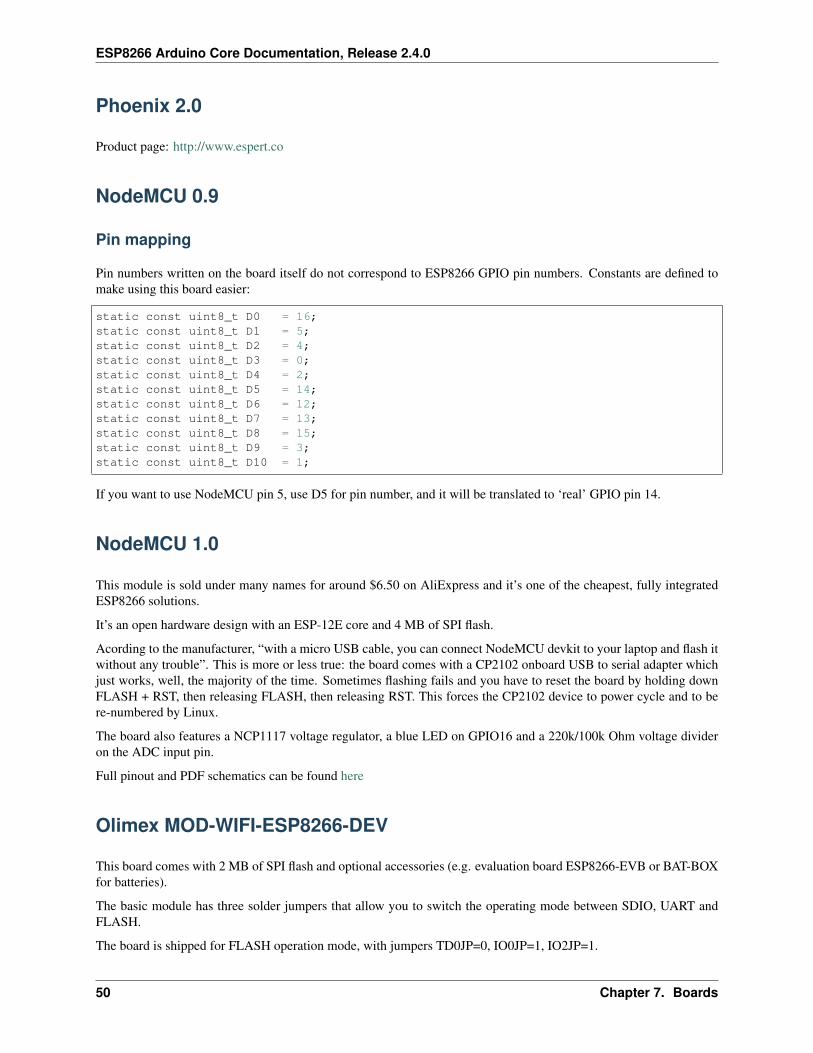
Pin mapping
Pin numbers written on the board itself do not correspond to ESP8266 GPIO pin numbers. Constants are defined tomake using this board easier:
static const uint8_t D0 = 16;static const uint8_t D1 = 5;static const uint8_t D2 = 4;static const uint8_t D3 = 0;static const uint8_t D4 = 2;static const uint8_t D5 = 14;static const uint8_t D6 = 12;static const uint8_t D7 = 13;static const uint8_t D8 = 15;static const uint8_t D9 = 3;static const uint8_t D10 = 1;
If you want to use NodeMCU pin 5, use D5 for pin number, and it will be translated to ‘real’ GPIO pin 14.
NodeMCU 1.0
This module is sold under many names for around $6.50 on AliExpress and it’s one of the cheapest, fully integratedESP8266 solutions.
It’s an open hardware design with an ESP-12E core and 4 MB of SPI flash.
Acording to the manufacturer, “with a micro USB cable, you can connect NodeMCU devkit to your laptop and flash itwithout any trouble”. This is more or less true: the board comes with a CP2102 onboard USB to serial adapter whichjust works, well, the majority of the time. Sometimes flashing fails and you have to reset the board by holding downFLASH + RST, then releasing FLASH, then releasing RST. This forces the CP2102 device to power cycle and to bere-numbered by Linux.
The board also features a NCP1117 voltage regulator, a blue LED on GPIO16 and a 220k/100k Ohm voltage divideron the ADC input pin.
Full pinout and PDF schematics can be found here
Olimex MOD-WIFI-ESP8266-DEV
This board comes with 2 MB of SPI flash and optional accessories (e.g. evaluation board ESP8266-EVB or BAT-BOXfor batteries).
The basic module has three solder jumpers that allow you to switch the operating mode between SDIO, UART andFLASH.
The board is shipped for FLASH operation mode, with jumpers TD0JP=0, IO0JP=1, IO2JP=1.
50 Chapter 7. Boards

ESP8266 Arduino Core Documentation, Release 2.4.0
Since jumper IO0JP is tied to GPIO0, which is PIN 21, you’ll have to ground it before programming with a USB toserial adapter and reset the board by power cycling it.
UART pins for programming and serial I/O are GPIO1 (TXD, pin 3) and GPIO3 (RXD, pin 4).
You can find the board schematics here
Olimex MOD-WIFI-ESP8266
This is a stripped down version of the above. Behaves identically in terms of jumpers but has less pins readily availablefor I/O. Still 2 MB of SPI flash.
Olimex ESP8266-EVB
It’s an Olimex MOD-WIFI-ESP8266-DEV module installed on the headers of a development board which featuressome breakout connectors, a button (GPIO0) and a relay (GPIO5).
To download a program you have to connect GND/RX/TX from a serial/USB adapter to the UEXT connector andpress the only button before applying power to enter UART mode.
Don’t connect 5V from the serial/USB adapter to the board or you won’t be able to power cycle it for UART mode.
You can find the board schematics here.
This guide is also useful for the first setup, since it contains the UEXT connector pinout.
Board variants include:
• ESP8266-EVB-BAT: comes with built-in LiPo charger and step-up converter
• ESP8266-EVB-BAT-BOX: as above, but enclosd in a plastic box (non-weatherproof)
SparkFun ESP8266 Thing
Product page: https://www.sparkfun.com/products/13231
TODO: add notes
SweetPea ESP-210
TODO: add notes
ESPino
ESPino integrates the ESP-12 module with a 3.3v regulator, CP2104 USB-Serial bridge and a micro USB connector foreasy programming. It is designed for fitting in a breadboard and has an RGB Led and two buttons for easy prototyping.
For more information about the hardware, pinout diagram and programming procedures, please see the datasheet.
Product page: http://www.espino.io/en
7.9. Olimex MOD-WIFI-ESP8266 51

ESP8266 Arduino Core Documentation, Release 2.4.0
WifInfo
WifInfo integrates the ESP-12 or ESP-07+Ext antenna module with a 3.3v regulator and the hardware to be able tomeasure French telemetry issue from ERDF powering meter serial output. It has a USB connector for powering, anRGB WS2812 Led, 4 pins I2C connector to fit OLED or sensor, and two buttons + FTDI connector and auto resetfeature.
For more information, please see WifInfo related blog entries, github and community forum.
Generic ESP8266 modules
These modules come in different form factors and pinouts. See the page at ESP8266 community wiki for more info:ESP8266 Module Family.
Usually these modules have no bootstapping resistors on board, insufficient decoupling capacitors, no voltage regula-tor, no reset circuit, and no USB-serial adapter. This makes using them somewhat tricky, compared to developmentboards which add these features.
In order to use these modules, make sure to observe the following:
• Provide sufficient power to the module. For stable use of the ESP8266 a power supply with 3.3V and >=250mA is required. Using the power available from USB to Serial adapter is not recommended, these adapterstypically do not supply enough current to run ESP8266 reliably in every situation. An external supply or regu-lator alongwith filtering capacitors is preferred.
• Connect bootstapping resistors to GPIO0, GPIO2, GPIO15 according to the schematics below.
• Put ESP8266 into bootloader mode before uploading code.
Serial Adapter
There are many different USB to Serial adapters / boards. To be able to put ESP8266 into bootloader mode using serialhandshaking lines, you need the adapter which breaks out RTS and DTR outputs. CTS and DSR are not useful forupload (they are inputs). Make sure the adapter can work with 3.3V IO voltage: it should have a jumper or a switch toselect between 5V and 3.3V, or be marked as 3.3V only.
Adapters based around the following ICs should work:
• FT232RL
• CP2102
• CH340G
PL2303-based adapters are known not to work on Mac OS X. See https://github.com/igrr/esptool-ck/issues/9 for moreinfo.
52 Chapter 7. Boards
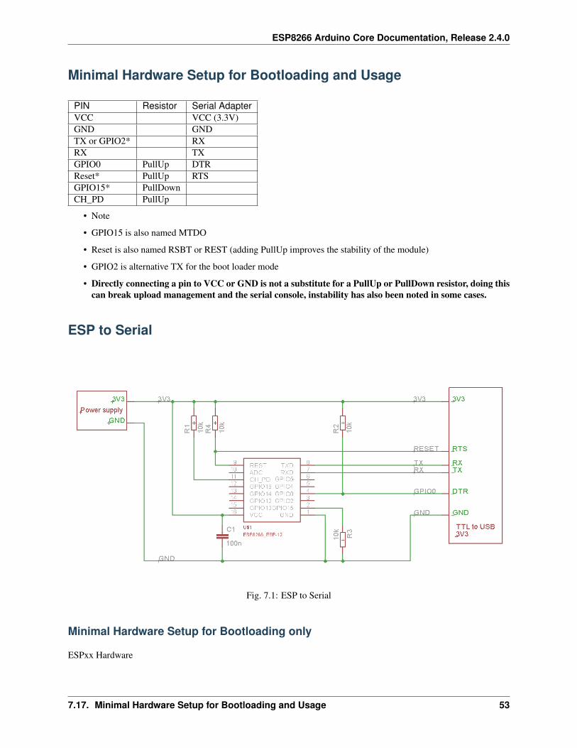
ESP8266 Arduino Core Documentation, Release 2.4.0
Minimal Hardware Setup for Bootloading and Usage
PIN Resistor Serial AdapterVCC VCC (3.3V)GND GNDTX or GPIO2* RXRX TXGPIO0 PullUp DTRReset* PullUp RTSGPIO15* PullDownCH_PD PullUp
• Note
• GPIO15 is also named MTDO
• Reset is also named RSBT or REST (adding PullUp improves the stability of the module)
• GPIO2 is alternative TX for the boot loader mode
• Directly connecting a pin to VCC or GND is not a substitute for a PullUp or PullDown resistor, doing thiscan break upload management and the serial console, instability has also been noted in some cases.
ESP to Serial
Fig. 7.1: ESP to Serial
Minimal Hardware Setup for Bootloading only
ESPxx Hardware
7.17. Minimal Hardware Setup for Bootloading and Usage 53

ESP8266 Arduino Core Documentation, Release 2.4.0
PIN Resistor Serial AdapterVCC VCC (3.3V)GND GNDTX or GPIO2 RXRX TXGPIO0 GNDReset RTS*GPIO15 PullDownCH_PD PullUp
• Note
• if no RTS is used a manual power toggle is needed
Minimal Hardware Setup for Running only
ESPxx Hardware
PIN Resistor Power supplyVCC VCC (3.3V)GND GNDGPIO0 PullUpGPIO15 PullDownCH_PD PullUp
Minimal
Fig. 7.2: ESP min
54 Chapter 7. Boards
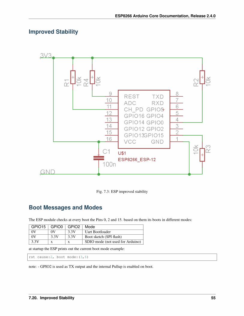
ESP8266 Arduino Core Documentation, Release 2.4.0
Improved Stability
Fig. 7.3: ESP improved stability
Boot Messages and Modes
The ESP module checks at every boot the Pins 0, 2 and 15. based on them its boots in different modes:
GPIO15 GPIO0 GPIO2 Mode0V 0V 3.3V Uart Bootloader0V 3.3V 3.3V Boot sketch (SPI flash)3.3V x x SDIO mode (not used for Arduino)
at startup the ESP prints out the current boot mode example:
rst cause:2, boot mode:(3,6)
note: - GPIO2 is used as TX output and the internal Pullup is enabled on boot.
7.20. Improved Stability 55

ESP8266 Arduino Core Documentation, Release 2.4.0
rst cause
Number Description0 unknown1 normal boot2 reset pin3 software reset4 watchdog reset
boot mode
the first value respects the pin setup of the Pins 0, 2 and 15.
Number GPIO15 GPIO0 GPIO2 Mode0 0V 0V 0V Not valid1 0V 0V 3.3V Uart2 0V 3.3V 0V Not valid3 0V 3.3V 3.3V Flash4 3.3V 0V 0V SDIO5 3.3V 0V 3.3V SDIO6 3.3V 3.3V 0V SDIO7 3.3V 3.3V 3.3V SDIO
note: - number = ((GPIO15 << 2) | (GPIO0 << 1) | GPIO2);
Generic ESP8285 modules
ESP8285 (datasheet) is a multi-chip package which contains ESP8266 and 1MB flash. All points related to bootstrap-ping resistors and recommended circuits listed above apply to ESP8285 as well.
Note that since ESP8285 has SPI flash memory internally connected in DOUT mode, pins 9 and 10 may be used asGPIO / I2C / PWM pins.
WeMos D1
Product page: https://www.wemos.cc/
WeMos D1 mini
Product page: https://www.wemos.cc/
ESPino (WROOM-02 Module) by ThaiEasyElec
ESPino by ThaiEasyElec using WROOM-02 module from Espressif Systems with 4 MB Flash.
We will update an English description soon. - Product page: http://thaieasyelec.com/products/wireless-modules/wifi-modules/espino-wifi-development-board-detail.html - Schematics:www.thaieasyelec.com/downloads/ETEE052/ETEE052_ESPino_Schematic.pdf - Dimensions: http://thaieasyelec.
56 Chapter 7. Boards

ESP8266 Arduino Core Documentation, Release 2.4.0
com/downloads/ETEE052/ETEE052_ESPino_Dimension.pdf - Pinouts: http://thaieasyelec.com/downloads/ETEE052/ETEE052_ESPino_User_Manual_TH_v1_0_20160204.pdf (Please see pg. 8)
gen4-IoD Range by 4D Systems
gen4-IoD Range of ESP8266 powered Display Modules by 4D Systems.
2.4”, 2.8” and 3.2” TFT LCD with uSD card socket and Resistive Touch. Chip Antenna + uFL Connector.
Datasheet and associated downloads can be found on the 4D Systems product page.
The gen4-IoD range can be programmed using the Arduino IDE and also the 4D Systems Workshop4 IDE, whichincorporates many additional graphics benefits. GFX4d library is available, along with a number of demo applications.
• Product page: http://www.4dsystems.com.au/product/gen4-IoD
7.26. gen4-IoD Range by 4D Systems 57

ESP8266 Arduino Core Documentation, Release 2.4.0
58 Chapter 7. Boards

CHAPTER 8
FAQ
The purpose of this FAQ / Troubleshooting is to respond to questions commonly asked in Issues section and onESP8266 Community forum.
Where possible we are going right to the answer and provide it within one or two paragraphs. If it takes more thanthat, you will see a link :arrow_right: to more details.
Please feel free to contribute if you believe that some frequent issues are not covered below.
I am getting “espcomm_sync failed” error when trying to upload myESP. How to resolve this issue?
This message indicates issue with uploading ESP module over a serial connection. There are couple of possible causes,that depend on the type of your module, if you use separate USB to serial converter.
Read more.
Why esptool is not listed in “Programmer” menu? How do I uploadESP without it?
Do not worry about “Programmer” menu of Arduino IDE. It doesn’t matter what is selected in it — upload now alwaysdefaults to using esptool.
Ref. #138, #653 and #739.
My ESP crashes running some code. How to troubleshoot it?
The code may crash because of s/w bug or issue with your h/w. Before entering an issue report, please perform initialtroubleshooting.
59

ESP8266 Arduino Core Documentation, Release 2.4.0
Read more.
This Arduino library doesn’t work on ESP. How do I make it working?
You would like to use this Arduino library with ESP8266 and it does not perform. It is not listed among librariesverified to work with ESP8266.
Read more.
In the IDE, for ESP-12E that has 4M flash, I can choose 4M (1MSPIFFS) or 4M (3M SPIFFS). No matter what I select, the IDE tellsme the maximum code space is about 1M. Where does my flashgo?
The reason we cannot have more than 1MB of code in flash has to do with a hardware limitation. Flash cache hardwareon the ESP8266 only allows mapping 1MB of code into the CPU address space at any given time. You can switchmapping offset, so technically you can have more than 1MB total, but switching such “banks” on the fly is not easyand efficient, so we don’t bother doing that. Besides, no one has so far complained about 1MB of code space beinginsufficient for practical purposes.
The option to choose 4M or 1M SPIFFS is to optimize the upload time. Uploading 3MB takes a long time so sometimesyou can just use 1MB. Other 2MB of flash can still be used with ESP.flashRead and ESP.flashWrite APIs ifnecessary.
I have observed a case when ESP.restart() doesn’t work. What is thereason for that?
You will see this issue only if serial upload was not followed by a physical reset (e.g. power-on reset). For a devicebeing in that state ESP.restart will not work. Apparently the issue is caused by one of internal registers not beingproperly updated until physical reset. This issue concerns only serial uploads. OTA uploads are not affected. If youare using ESP.restart, the work around is to reset ESP once after each serial upload.
Ref. #1017, #1107, #1782
How to resolve “Board generic (platform esp8266, package esp8266)is unknown” error?
This error may pop up after switching between staging and stable esp8266 / Arduino package installations, or afterupgrading the package version Read more.
60 Chapter 8. FAQ

CHAPTER 9
Exception Causes (EXCCAUSE)
EXCCAU SE Code Cause Name Cause Description Required Option EXCVAD DR Loaded0 IllegalIns tructionCa use Illegal instruction Exception No1 SyscallCau se SYSCALL instruction Exception No2 Instructio nFetchErro rCause Processor internal physical address or data error during instruction fetch Exception Yes3 LoadStoreE rrorCause Processor internal physical address or data error during load or store Exception Yes4 Level1Inte rruptCause Level-1 interrupt as indicated by set level-1 bits in the INTERRUPT register Interrupt No5 AllocaCaus e MOVSP instruction, if caller’s registers are not in the register file Windowed Register No6 IntegerDiv ideByZeroC ause QUOS, QUOU, REMS, or REMU divisor operand is zero 32-bit Integer Divide No7 Reserved for Tensilica8 Privileged Cause Attempt to execute a privileged operation when CRING != 0 MMU No9 LoadStoreA lignmentCa use Load or store to an unaligned address Unaligned Exception Yes10..11 Reserved for Tensilica12 InstrPIFDa taErrorCau se PIF data error during instruction fetch Processor Interface Yes13 LoadStoreP IFDataErro rCause Synchronous PIF data error during LoadStore access Processor Interface Yes14 InstrPIFAd drErrorCau se PIF address error during instruction fetch Processor Interface Yes15 LoadStoreP IFAddrErro rCause Synchronous PIF address error during LoadStore access Processor Interface Yes16 InstTLBMis sCause Error during Instruction TLB refill MMU Yes17 InstTLBMul tiHitCause Multiple instruction TLB entries matched MMU Yes18 InstFetchP rivilegeCa use An instruction fetch referenced a virtual address at a ring level less than CRING MMU Yes19 Reserved for Tensilica20 InstFetchP rohibitedC ause An instruction fetch referenced a page mapped with an attribute that does not permit instruction fetch Region Protectio n or MMU Yes21..23 Reserved for Tensilica24 LoadStoreT LBMissCaus e Error during TLB refill for a load or store MMU Yes25 LoadStoreT LBMultiHit Cause Multiple TLB entries matched for a load or store MMU Yes26 LoadStoreP rivilegeCa use A load or store referenced a virtual address at a ring level less than CRING MMU Yes27 Reserved for Tensilica28 LoadProhib itedCause A load referenced a page mapped with an attribute that does not permit loads Region Protectio n or MMU Yes29 StoreProhi bitedCause A store referenced a page mapped with an attribute that does not permit stores Region Protectio n or MMU Yes30..31 Reserved for Tensilica32..39 Coprocesso rnDisabled Coprocessor n instruction when cpn disabled. n varies 0..7 as the cause varies 32..39 Coprocess or No
Continued on next page
61

ESP8266 Arduino Core Documentation, Release 2.4.0
Table 9.1 – continued from previous pageEXCCAU SE Code Cause Name Cause Description Required Option EXCVAD DR Loaded40..63 Reserved
Infos from Xtensa Instruction Set Architecture (ISA) Reference Manual
62 Chapter 9. Exception Causes (EXCCAUSE)

CHAPTER 10
Debugging
Introduction
Since 2.1.0-rc1 the core includes a Debugging feature that is controllable over the IDE menu.
The new menu points manage the real-time Debug messages.
Requirements
For usage of the debugging a Serial connection is required (Serial or Serial1).
The Serial Interface need to be initialized in the setup().
Set the Serial baud rate as high as possible for your Hardware setup.
Minimum sketch to use debugging:
void setup() {Serial.begin(115200);
}
void loop() {}
63
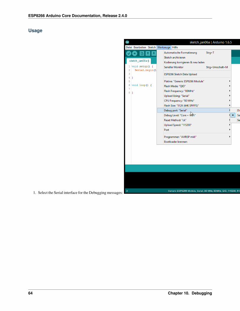
ESP8266 Arduino Core Documentation, Release 2.4.0
Usage
1. Select the Serial interface for the Debugging messages:
64 Chapter 10. Debugging

ESP8266 Arduino Core Documentation, Release 2.4.0
2. Select which type / level you want debug messages for:
3. Check if the Serial interface is initialized in setup() (see Requirements)
4. Flash sketch
5. Check the Serial Output
Informations
It work with every sketch that enables the Serial interface that is selected as debug port.
The Serial interface can still be used normal in the Sketch.
The debug output is additional and will not disable any interface from usage in the sketch.
For Developers
For the debug handling uses defines.
The defined are set by command line.
10.2. Informations 65
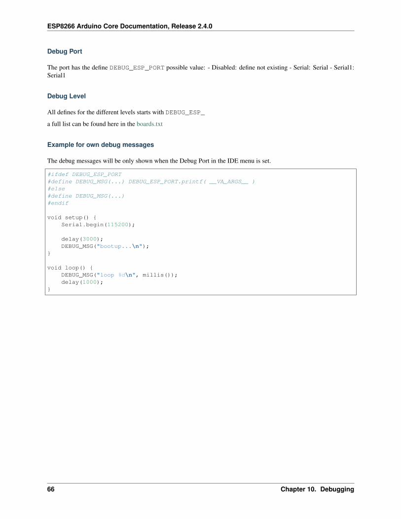
ESP8266 Arduino Core Documentation, Release 2.4.0
Debug Port
The port has the define DEBUG_ESP_PORT possible value: - Disabled: define not existing - Serial: Serial - Serial1:Serial1
Debug Level
All defines for the different levels starts with DEBUG_ESP_
a full list can be found here in the boards.txt
Example for own debug messages
The debug messages will be only shown when the Debug Port in the IDE menu is set.
#ifdef DEBUG_ESP_PORT#define DEBUG_MSG(...) DEBUG_ESP_PORT.printf( __VA_ARGS__ )#else#define DEBUG_MSG(...)#endif
void setup() {Serial.begin(115200);
delay(3000);DEBUG_MSG("bootup...\n");
}
void loop() {DEBUG_MSG("loop %d\n", millis());delay(1000);
}
66 Chapter 10. Debugging
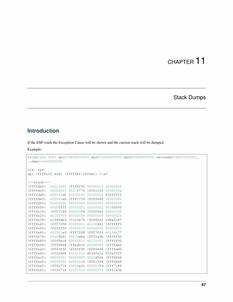
CHAPTER 11
Stack Dumps
Introduction
If the ESP crash the Exception Cause will be shown and the current stack will be dumped.
Example:
Exception (0): epc1=0x402103f4 epc2=0x00000000 epc3=0x00000000 excvaddr=0x00000000→˓depc=0x00000000
ctx: syssp: 3ffffc10 end: 3fffffb0 offset: 01a0
>>>stack>>>3ffffdb0: 40223e00 3fff6f50 00000010 600006003ffffdc0: 00000001 4021f774 3fffc250 4000050c3ffffdd0: 400043d5 00000030 00000016 ffffffff3ffffde0: 400044ab 3fffc718 3ffffed0 080000003ffffdf0: 60000200 08000000 00000003 000000003ffffe00: 0000ffff 00000001 04000002 003fd0003ffffe10: 3fff7188 000003fd 3fff2564 000000303ffffe20: 40101709 00000008 00000008 000000203ffffe30: c1948db3 394c5e70 7f2060f2 c6ba0c873ffffe40: 3fff7058 00000001 40238d41 3fff6ff03ffffe50: 3fff6f50 00000010 60000600 000000203ffffe60: 402301a8 3fff7098 3fff7014 40238c773ffffe70: 4022fb6c 40230ebe 3fff1a5b 3fff6f003ffffe80: 3ffffec8 00000010 40231061 3fff0f903ffffe90: 3fff6848 3ffed0c0 60000600 3fff6ae03ffffea0: 3fff0f90 3fff0f90 3fff6848 3fff6d403ffffeb0: 3fff28e8 40101233 d634fe1a fffeffff3ffffec0: 00000001 00000000 4022d5d6 3fff68483ffffed0: 00000002 4000410f 3fff2394 3fff68483ffffee0: 3fffc718 40004a3c 000003fd 3fff71883ffffef0: 3fffc718 40101510 00000378 3fff1a5b
67

ESP8266 Arduino Core Documentation, Release 2.4.0
3fffff00: 000003fd 4021d2e7 00000378 000003ff3fffff10: 00001000 4021d37d 3fff2564 000003ff3fffff20: 000003fd 60000600 003fd000 3fff25643fffff30: ffffff00 55aa55aa 00000312 0000001c3fffff40: 0000001c 0000008a 0000006d 000003ff3fffff50: 4021d224 3ffecf90 00000000 3ffed0c03fffff60: 00000001 4021c2e9 00000003 3fff12383fffff70: 4021c071 3ffecf84 3ffecf30 0026a2b03fffff80: 4021c0b6 3fffdab0 00000000 3fffdcb03fffff90: 3ffecf40 3fffdab0 00000000 3fffdcc03fffffa0: 40000f49 40000f49 3fffdab0 40000f49<<<stack<<<
The first number after Exception gives the cause of the reset. a full ist of all causes can be found here the hex afterare the stack dump.
Decode
It’s possible to decode the Stack to readable information. For more info see the Esp Exception Decoder tool.
Fig. 11.1: ESP Exception Decoder
68 Chapter 11. Stack Dumps
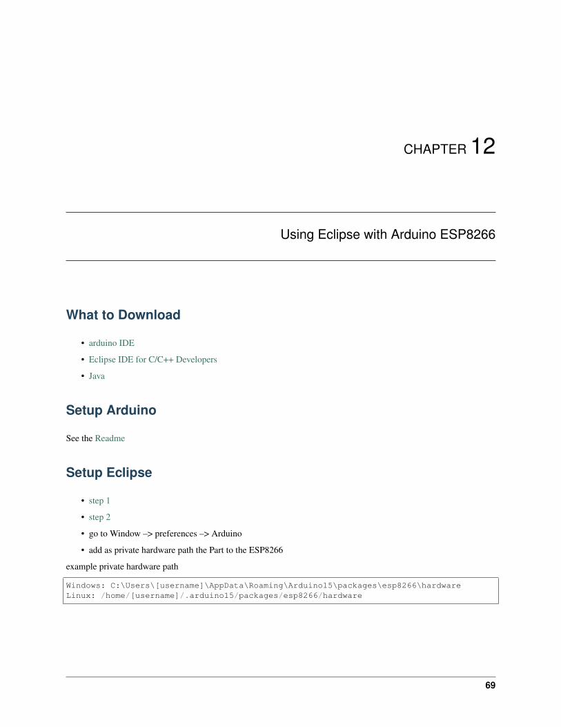
CHAPTER 12
Using Eclipse with Arduino ESP8266
What to Download
• arduino IDE
• Eclipse IDE for C/C++ Developers
• Java
Setup Arduino
See the Readme
Setup Eclipse
• step 1
• step 2
• go to Window –> preferences –> Arduino
• add as private hardware path the Part to the ESP8266
example private hardware path
Windows: C:\Users\[username]\AppData\Roaming\Arduino15\packages\esp8266\hardwareLinux: /home/[username]/.arduino15/packages/esp8266/hardware
69

ESP8266 Arduino Core Documentation, Release 2.4.0
Eclipse wont build
if eclipse dont find the path to the Compiler add to the platform.txt after:
version=1.6.4
this:
runtime.tools.xtensa-lx106-elf-gcc.path={runtime.platform.path}/../../../tools/xtensa-→˓lx106-elf-gcc/1.20.0-26-gb404fb9runtime.tools.esptool.path={runtime.platform.path}/../../../tools/esptool/0.4.4
Note: - the path may changed, check the current version. - each update over the Arduino IDE will remove the fix -may not needed in future if Eclipse Plugin get an Update
70 Chapter 12. Using Eclipse with Arduino ESP8266

CHAPTER 13
Changelog
2.3.0
June 23, 2016
Package link: http://arduino.esp8266.com/versions/2.3.0/package_esp8266com_index.json.
Core
• Fix NMI interrupt handler alignment
• Update SDK to 1.5.3
• umm_malloc: print block start address before heap corruption callback is triggered
• If GDBStub library is used, break into gdb on assert and panic
• Add option to keep FS classes in namespace (#2030)
• Add SPIFFS::end (#1657)
• Add ArduinoOTA::getHostname() interface
• Add __throw_out_of_range
• Add support for RTC user memory in ESP-specific APIs. (#1836)
• Expose RTC_USER_MEM in esp8266_peri.h
• Remove DISABLED macro (#2072)
• Execute global constructors in correct order (#2074)
• Real board name available in Sketch/MDNS/OTA (#2054)
• Add DOUT/QOUT flash modes
• Add ESP8285 entry in boards menu
71

ESP8266 Arduino Core Documentation, Release 2.4.0
• Move timer detachInterrupt functions into IRAM (#2083)
• Make Updater be able to run inside async callbacks (#2096)
• Add new boards Phoenix 1.0 & Phoenix 2.0 (#2088)
• Store git version of the core in the compiled binary (#2099)
• Rebuild libstdc++ with mlongcalls and link against it (#1983)
• Add mechanism for posting functions to the main loop (#2082)
• MD5Builder::addStream: fixed falsy calculated hash for len > filelength (#2126)
• Fix SPIFFS.openDir(“”) (#2143)
• Bring back old semantics to random and randomSeed, add secureRandom (#1710) (#2142)
• Add missing pgm_read_ptr{_near/_far} macros (#2160)
• Add macro for maximum open SPIFFS files, settings it to 1 saves about 1k heap. (#2167)
• Fix UART pins setting (#2098)
• Fix ESP.getSketchSize, add ESP.getSketchMD5 (#2158)
• Add Serial.baudRate() to get current baud rate (#2079)
Libraries
• SNI support in WiFiClientSecure (#1285)
• Update axTLS to 139914f
• HTTPClient: return error when HTTPClient::begin is called with HTTPS URL without certificate fingerprint(#1941)
• HTTPClient: fix default port not being set
• HTTPClient: fix handling of chunked transfer encoding (#1975)
• ESP8266SSDP: switch SSDP send arguments around
• ESP8266WiFi: fix UdpContext::peek to return int (#1946)
• ESP8266WiFi: fix WiFiSleepType_t values to match SDK ones
• LwIP: use gcc-built LwIP by default (#1926)
• LwIP: fix crash in igmp_start_timer (#1826)
• HTTPClient: include non-standard ports in Host: header
• ESP8266WiFi: Prevent WiFi config corruption (#1997 #1856 #1699 #1675)
• GDBStub: fix section attribute for core gdbstub functions
• Wire: I2C bus reset with info to user
• ESP8266HTTPClient: allow HTTP header value without LWS
• ESP8266mDNS: Fix mDNS doesn’t accept queryService responses from avahi-daemon (#2015)
• Add MFRC522 to supported libraries (#2044)
• Update axTLS to ab516f7 (1.5.3+)
• Mention ESP8266Ping library
72 Chapter 13. Changelog
ESP8266 Arduino Core Documentation, Release 2.4.0
• ESP8266HTTPClient: fix duplicate Content-Length headers (#1902)
• ESP8266HTTPUpdateServer: make HTTP Update Server more secure (#2104)
• ESP8266WiFi: add virtual destructor to WiFiServer class (#2116)
• ESP8266WiFi: fix error when calling WiFiServer::close more than once
• ESP8266WiFi: WiFi event handling refactoring (#2119)
• ESP8266mDNS: restart listening when WiFi STA is connected/disconnected (#1828)
• ESP8266WiFi: allow DHCP client to be re-enabled using WiFi.config(0U, 0U, 0U) (#1896)
• ESP8266WiFi: enable SO_REUSE in LwIP and WiFiServer (#1431)
• ESP8266WebServer: make ESP8266WebServer::urlDecode public (#1419)
• LwIP: sntp_localtime: return -1 in tm_isdst field (#2010)
• ESP8266WiFi: fix for crash in WiFiClientSecure when WiFi is disconnected (#2139)
• SD: Prevent WDT resets in SD library (#1815)
• ESP8266WiFi: Fix issue when WiFi.begin(ssid, pass) is called right after WiFi.mode(WIFI_OFF)
Tools
• Python 3 compatibility for get.py
• Device side test library and test runner
• Fix ARM toolchain files permissions (#2004)
• Update esptool to 0.4.9
2.2.0
April 18, 2016
Package link: http://arduino.esp8266.com/versions/2.2.0/package_esp8266com_index.json.
Core
• Leverage realloc() in String::changeBuffer()
• Clean up core files
• Add host side tests
• Fix possible null pointer in umm_malloc
• Remove “Upload Using” option from Tools menu
• Move attachInterrupt and detachInterrupt into IRAM (#1734)
• Implement strstr_P
• Allow indefinite duration for tone()
• Fix crashes when using tone()
13.2. 2.2.0 73

ESP8266 Arduino Core Documentation, Release 2.4.0
• Fix RF_MODE and ADC_MODE
• Move micros, delayMicroseconds, millis to IRAM (#1326)
• Fix pulseIn (#1072, #1149)
• Accept both named constant and ADC channel number in analogRead (#1766)
• Enable heap poisoning only when debug options are enabled (#1800)
• Bootloader: don’t touch RTC memory if it doesn’t contain a valid command (#619)
• Update SDK to 1.5.2 (#1653)
• Clean up variants, fix digitalPinHasPWM definition (#1831)
• Don’t set RF mode on boot unless it was overridden
• Change build.board property for boards which renumber pins like NodeMCU (#1878)
• Fix Exception 2 when using printf or vprintf
Libraries
• Update axTLS to 5b4be7d
• WiFiClientSecure: implement connection timeout, fix connected method behavior
• WiFiClient: fix write behavior when connection is closed by remote side
• ESP8266HTTPServer: add font MIME types, fix #1601
• ESP8266mDNS: add client support
• Update SPIFFS to 82aeac6
• Servo: move some functions into IRAM (#1742)
• Update SoftwareSerial to version 3.1.0
• ESP8266SSDP: change templates to include deviceType
• ESP8266WebServer: handle more file types
• SPI: add CPOL setting
• ESP8266WebServer: Fix buffer overflow in ESP8266WebServer::authenticate (#1790)
• ESP8266WiFi: fix undefined behavior in WiFiServer::setNoDelay (#1695)
• Servo: use peripheral clock frequency when calculating FRC1 tick count (#1789)
• ESP8266WiFi: avoid multiple instances of INADDR_NONE
• Add LwIP binary built with gcc
• ESP8266WiFi: Allow PSK instead of passphrase in WiFiSTA::begin
• SPI: Fix SPI.transfer16() using wrong endianness
• HTTPClient: decouple transport layer handling + save some RAM
• ESP8266httpUpdate: decouple HTTPS overloads + save some RAM
• Update and move lwIP headers, add options to use different lwIP build
• ESP8266WebServer: wait for data to arrive
• ESP8266WebServer: save RAM by moving response strings to flash (#1732)
74 Chapter 13. Changelog

ESP8266 Arduino Core Documentation, Release 2.4.0
• SPI: Speed up SPI.writePattern()
Tools
• Add ARM tools (#269)
2.0.0
November 30, 2015
Package link: http://arduino.esp8266.com/versions/2.0.0/package_esp8266com_index.json.
Core
• Add file system APIs and documentation
• Add ConfigFile example
• Allow user to run code in user_rf_pre_init
• Add strtoul and strtol, fix strtod
• Update documentation for NodeMCU and Olimex boards
• Disable interrupts inside ESP.getVcc (#567)
• Erase RTC RAM only if RF mode looks invalid (#619)
• Get pin levels at time of interrupt, rather than the time of calling the handler.
• Move interrupt handlers to ram.
• Improve debug output on critical errors
• Add ArduinoOTA library and docs
• Add WeMos D1 & D1 mini boards
• Add documentation about boot messages and mode meaning
• Disable sleep mode before doing OTA (#1005)
• Add the ability to be called back when the device is about to reset
• Add “Reset Method” menu
• Add MD5 to core
• I2C: generate STOP in case of NACK (fix #698, #254)
• Add libc time functions
• Fix linker script for 512k(no SPIFFS) variant (#966)
• I2S optimizations
• Support Sketch > Export compiled binary
• Update SPIFFS wrapper for 0.3.3
• Fix placement of code into RAM, enable gc-sections
13.3. 2.0.0 75

ESP8266 Arduino Core Documentation, Release 2.4.0
• Make soft wdt reset more obvious
• Force disable IOSWAP for UART0 in HardwareSerial initialization (#744)
• Add IPAddress::toString()
Libraries
• ESP8266WebServer: support for sending of PROGMEM strings
• ESP8266WebServer: support for serving files from file system
• ESP8266WiFi: fix mode selection (#529)
• ESP8266mDNS: allow to work on SoftAP interface
• EEPROM: round requested size to 4 bytes (#659)
• Add ESP8266AVRISP library
• Add ESP8266HTTPUpdate library
• Add HTTPClient library
• Add WiFiClientSecure
• ESP8266WiFi library: add persistent option, fix #1054
• Make RequestHandler handle uploads
• Add Digest Authentication to OTA and espota.py
• Don’t close UDP pcbs when WiFi connection drops (#969)
• Add espsoftwareserial library
• Add HTTP Updater library
• Add Ethernet library for W5100
• Add SPIFFS WebServer Example
• add dnsIP() to ESP8266WiFi class
• OTA support encapsulated to ArduinoOTA class
• Add gdb stub library
• Extracted the WebUpdate example into a library.
• Fix to Servo allowing write() to be called before attach()
• ESP8266WiFi: add function begin without any parameters and add psk function to return current PSK formsdk config
• Fix a crash due to abort() called from TCP error callback (#428)
• Adding support for OPTIONS requests to ESP8266WebServer
• Add HTTPS request sample (#43)
• Fix _useClientMode & _useApMode in SDK auto connect mode (#754)
• Add ESP8266WebServer::sendContent_P with ‘size_t size’ argument for binary content
• Fix bug in WiFiClient::write_P when content was binary
• Add WiFiClient::write_P to be used with PROGMEM
76 Chapter 13. Changelog

ESP8266 Arduino Core Documentation, Release 2.4.0
Tools
• Update SDK to 1.3.0_15_08_10_p1
• Update esptool to 0.4.6
• Bump toolchain version to force libm update on Windows
• ESP8266FS tool update
1.6.4-673-g8cd3697
May 22, 2015
Package link: http://arduino.esp8266.com/versions/1.6.4-673-g8cd3697/package_esp8266com_index.json.
Tools
• Add 32-bit Linux toolchain.
• Rebuild toolchain and esptool with support for OS X down to 10.6.
Libraries
• Better connection handling in ESP8266WebServer. The server now sends Content-Length and Connection:close headers, then waits for the client to disconnect. By not closing the connection actively, server avoidsTIME_WAIT TCP state, and TCP stack is able to release the memory immediately, without waiting for 2xMSLperiod. If the client doesn’t disconnect in 2000ms, the server closes the connection actively.
• Add Hash library, which has a function to calculate SHA1 hash.
• SD, Adafruit_ILI9341, and OneWire libraries are now bundled.
• Fix incorrect sector calculation in EEPROM library.
1.6.4-628-g545ffde
May 19, 2015
• Initial release of Boards Manager package for ESP8266 platform.
13.4. 1.6.4-673-g8cd3697 77