Embed Size (px)
Citation preview

ESP32 AT Instruction Set and Examples
Version 1.3 Espressif Systems Copyright © 2019

About This Guide This document introduces the ESP32 AT commands, explains how to use them and provides examples of several common AT commands.
Release Notes
Documentation Change Notification Espressif provides email notifications to keep customers updated on changes to technical documentation. Please subscribe at https://www.espressif.com/en/subscribe.
Certification Download certificates for Espressif products from https://www.espressif.com/en/certificates.
Date Version Release notes
2017.11 V1.0 Initial release.
2018.06 V1.1
Updated Section 4.2.15,5.2.8,5.2.15,6.2.5,6.2.11 and Chapter 8.
Added Section 5.2.9,6.2.29,6.2.30,9.5.2.2.
2018.12 V1.2 Update Chapter 1 and Section 5.2.3.
2019.06 V1.3 Corrected a typo in Section 4.2.3.

Table of Contents 1. Overview 1 ................................................................................................................................
1.1. User-Defined AT Commands 1.....................................................................................................1.2. Downloading AT Firmware into Flash 1.........................................................................................
2. Command Description 3 ..........................................................................................................
3. Basic AT Commands 4 .............................................................................................................3.1. Overview 4....................................................................................................................................
3.2. Commands 4.................................................................................................................................3.2.1. AT—Tests AT Startup 4..................................................................................................................3.2.2. AT+RST—Restarts the Module 4..................................................................................................3.2.3. AT+GMR—Checks Version Information 5....................................................................................3.2.4. AT+GSLP—Enters Deep-sleep Mode 5.......................................................................................3.2.5. ATE—AT Commands Echoing 5....................................................................................................
3.2.6. AT+RESTORE—Restores the Factory Default Settings 5...........................................................3.2.7. AT+UART_CUR—Current UART Configuration, Not Saved in Flash 6......................................3.2.8. AT+UART_DEF—Default UART Configuration, Saved in Flash 7...............................................3.2.9. AT+SLEEP—Sets the Sleep Mode 8............................................................................................3.2.10. AT+SYSRAM—Checks the Remaining Space of RAM 8............................................................3.2.11. AT+SYSFLASH—Set User Partitions in Flash * 8........................................................................
3.2.12. AT+FS—Filesystem Operations * 9...............................................................................................3.2.13. AT+RFPOWER—Set RF TX Power * 11.......................................................................................
4. Wi-Fi AT Commands 12 ............................................................................................................4.1. Overview 12..................................................................................................................................
4.2. Commands 12...............................................................................................................................4.2.1. AT+CWMODE—Sets the Wi-Fi Mode (Station/SoftAP/Station+SoftAP) 12..............................4.2.2. AT+CWJAP—Connects to an AP 14............................................................................................4.2.3. AT+CWLAPOPT—Sets the Configuration for the Command AT+CWLAP 15...........................4.2.4. AT+CWLAP—Lists the Available APs 16......................................................................................4.2.5. AT+CWQAP—Disconnects from the AP 16.................................................................................
4.2.6. AT+CWSAP—Configuration of the ESP32 SoftAP 17.................................................................4.2.7. AT+CWLIF—IP of Stations to Which the ESP32 SoftAP is Connected 18................................4.2.8. AT+CWDHCP—Enables/Disables DHCP 18...............................................................................

4.2.9. AT+CWDHCPS—Sets the IP Address Allocated by ESP32 SoftAP DHCP (The configuration is saved in Flash.) 19.................................................................................................................
4.2.10. AT+CWAUTOCONN—Auto-Connects to the AP or Not 19........................................................4.2.11. AT+CWSTARTSMART—Starts SmartConfig 20..........................................................................4.2.12. AT+CWSTOPSMART—Stops SmartConfig 20............................................................................4.2.13. AT+WPS—Enables the WPS Function 21....................................................................................4.2.14. AT+CWHOSTNAME—Configures the Host Name of ESP32 Station * 21.................................
4.2.15. AT+MDNS—Configures the MDNS Function * 21.......................................................................
5. TCP/IP-Related AT Commands 23 ..........................................................................................5.1. Overview 23..................................................................................................................................5.2. Commands 24...............................................................................................................................
5.2.1. AT+CIPSTATUS—Gets the Connection Status 24.......................................................................5.2.2. AT+CIPDOMAIN—DNS Function 24............................................................................................5.2.3. AT+CIPDNS—Sets User-defined DNS Servers; Configuration Saved in the Flash 24.............5.2.4. AT+CIPSTAMAC—Sets the MAC Address of the ESP32 Station 25.........................................5.2.5. AT+CIPAPMAC—Sets the MAC Address of the ESP32 SoftAP 25...........................................5.2.6. AT+CIPSTA—Sets the IP Address of the ESP32 Station 26.......................................................
5.2.7. AT+CIPAP—Sets the IP Address of the ESP32 SoftAP 26.........................................................5.2.8. AT+CIPSTART—Establishes TCP Connection, UDP Transmission or SSL Connection 27.....5.2.9. AT+CIPSSLCCONF—Set Configuration of SSL Client * 29........................................................5.2.10. AT+CIPSEND—Sends Data 30.....................................................................................................5.2.11. AT+CIPSENDEX—Sends Data 31.................................................................................................5.2.12. AT+CIPCLOSE—Closes TCP/UDP/SSL Connection 31............................................................
5.2.13. AT+CIFSR—Gets the Local IP Address 32...................................................................................5.2.14. AT+CIPMUX—Enables/Disables Multiple Connections 32.........................................................5.2.15. AT+CIPSERVER—Deletes/Creates TCP or SSL Server * 33......................................................5.2.16. AT+CIPSERVERMAXCONN—Set the Maximum Connections Allowed by Server * 33...........5.2.17. AT+CIPMODE—Configures the Transmission Mode 34.............................................................5.2.18. AT+SAVETRANSLINK—Saves the Transparent Transmission Link in Flash 35........................
5.2.19. AT+CIPSTO—Sets the TCP Server Timeout 36...........................................................................5.2.20. AT+CIPSNTPCFG—Sets the Time Zone and the SNTP Server 37............................................5.2.21. AT+CIPSNTPTIME—Queries the SNTP Time 37.........................................................................5.2.22. AT+CIUPDATE—Updates the Software Through Wi-Fi 37.........................................................5.2.23. AT+CIPDINFO—Shows the Remote IP and Port with "+IPD" 38...............................................5.2.24. +IPD—Receives Network Data 38................................................................................................

5.2.25. AT+PING—Ping Packets 39..........................................................................................................
6. BLE-Related AT Commands 40 ...............................................................................................6.1. Overview 40..................................................................................................................................6.2. Commands 42...............................................................................................................................
6.2.1. AT+BLEINIT—BLE Initialization 42................................................................................................6.2.2. AT+BLEADDR—Sets BLE Device's Address 42..........................................................................
6.2.3. AT+BLENAME—Sets BLE Device's Name 43.............................................................................6.2.4. AT+BLESCANPARAM—Sets Parameters of BLE Scanning 43.................................................6.2.5. AT+BLESCAN—Enables BLE Scanning 44.................................................................................6.2.6. AT+BLESCANRSPDATA—Sets BLE Scan Response 45............................................................6.2.7. AT+BLEADVPARAM—Sets Parameters of Advertising 46..........................................................
6.2.8. AT+BLEADVDATA—Sets Advertising Data 47.............................................................................6.2.9. AT+BLEADVSTART—Starts Advertising 47..................................................................................6.2.10. AT+BLEADVSTOP—Stops Advertising 47...................................................................................6.2.11. AT+BLECONN—Establishes BLE connection 48........................................................................6.2.12. AT+BLECONNPARAM—Updates parameters of BLE connection 48.......................................6.2.13. AT+BLEDISCONN—Ends BLE connection 49............................................................................
6.2.14. AT+BLEDATALEN—Sets BLE Data Packet Length 49................................................................6.2.15. AT+BLECFGMTU—Sets GATT MTU Length 50..........................................................................6.2.16. AT+BLEGATTSSRVCRE—GATTS Creates Services 50..............................................................6.2.17. AT+BLEGATTSSRVSTART—GATTS Starts Services 51.............................................................6.2.18. AT+BLEGATTSSRVSTOP—GATTS Stops Services 51...............................................................6.2.19. AT+BLEGATTSSRV—GATTS Discovers Services 51..................................................................
6.2.20. AT+BLEGATTSCHAR—GATTS Discovers Characteristics 52....................................................6.2.21. AT+BLEGATTSNTFY—GATTS Notifies of Characteristics 52.....................................................6.2.22. AT+BLEGATTSIND—GATTS Indicates Characteristics 53..........................................................6.2.23. AT+BLEGATTSSETATTR—GATTS Sets Characteristic 54..........................................................6.2.24. AT+BLEGATTCPRIMSRV—GATTC Discovers Primary Services 55..........................................6.2.25. AT+BLEGATTCINCLSRV—GATTC Discovers Included Services 55.........................................
6.2.26. AT+BLEGATTCCHAR—GATTC Discovers Characteristics 56...................................................6.2.27. AT+BLEGATTCRD—GATTC Reads a Characteristic 56.............................................................6.2.28. AT+BLEGATTCWR—GATTC Writes Characteristic 57................................................................6.2.29. AT+BLESPPCFG—Configures BLE SPP 58................................................................................6.2.30. AT+BLESPP—Enables BLE SPP 60.............................................................................................

6.2.31. AT+BLESECPARAM—Set Parameters of BLE SMP 61..............................................................
6.2.32. AT+BLEENC—Starts a Pairing Request 62..................................................................................6.2.33. AT+BLEENCRSP—Sets a Pairing Response 63..........................................................................6.2.34. AT+BLEKEYREPLY—Reply to a Pairing Key 63..........................................................................6.2.35. AT+BLECONFREPLY—Reply to a Pairing Result 63...................................................................6.2.36. AT+BLEENCDEV—Lists All Devices that Bonded 64..................................................................6.2.37. AT+BLEENCCLEAR—Unbind Device 64.....................................................................................
7. AT Commands with Configuration Saved in the NVS Area 65 ................................................
8. AT Messages 66 ........................................................................................................................
9. AT Commands Examples 67 ....................................................................................................9.1. ESP32 as a TCP Client in Single Connection 67..........................................................................9.2. UDP Transmission 68....................................................................................................................
9.2.1. UDP (with Fixed Remote IP and Port) 68......................................................................................9.2.2. UDP (with Changeable Remote IP and Port) 69..........................................................................
9.3. Transparent Transmission 70........................................................................................................9.3.1. ESP32 as a TCP Client in UART-Wi-Fi Passthrough (Single Connection Mode) 71..................9.3.2. UDP Transmission (UART-Wi-Fi PassthroughTransmission) 72..................................................
9.4. ESP32 as a TCP Server in Multiple Connections 74....................................................................9.5. BLE AT Examples 76....................................................................................................................
9.5.1. iBeacon Examples 76.....................................................................................................................
9.5.2. BLE Communication Examples 78...............................................................................................
10.OTA Update 90 .........................................................................................................................
11.Q & A 96....................................................................................................................................

!
1. Overview
1. Overview This document introduces the ESP32 AT commands, and explains how to use them.
The AT command set is divided into different categories: Basic AT commands, Wi-Fi AT commands, TCP/IP AT commands, etc.
Please note that the AT commands marked with * are beta versions that have not been fully tested.
1.1. User-Defined AT Commands Please use only English letters or an underscore (_), when naming user-defined AT commands. The AT command name must NOT contain characters or numbers.
AT firmware is based on the Espressif IoT Development Framework (ESP-IDF). Espressif Systems' AT commands are provided in libat_core.a, which is included in the AT BIN firmware. Examples of customized, user-defined AT commands are provided in esp-at.
The structure, at_cmd_struct, is used to define four types of a command. Examples of implementing user-defined AT commands are provided in /esp32-at/main/interface/uart/at_uart_task.c.
1.2. Downloading AT Firmware into Flash Please use Espressif's official Flash Download Tools to download the firmware. Make sure you select the corresponding flash size.
Espressif's official Flash Download Tools: http://espressif.com/en/support/download/other-tools?keys=&field_type_tid%5B%5D=13.
Download ESP32_AT_BIN: http://www.espressif.com/en/support/download/at.
The flashing addresses are in /ESP32_AT_BIN/download.config.
Please note that there are several binaries for some specific functions, they are listed as below:
• at_customize.bin is to provide a user partition table, which lists different partitions for the ble_data.bin, SSL certificates, and factory_param_XXX.bin. Furthermore, users can add their own users partitions, and read/write the user partitions with the command AT+FS and AT+SYSFLASH.
• factory_param_XXX.bin indicates the hardware configurations for different ESP modules. Please make sure the correct bin is used for your specific module. If users design their own module, they can configure it with reference to the esp32-at/docs/ESP32_AT_Factory_Parameter_Bin.md, and the binaries will be automatically
📖 Note:
For codes related to ESP32 AT instruction set, please refer to https://github.com/espressif/esp32-at.
Espressif ! /!1 97 2019.06

!
1. Overview
generated after compilation. When users flash the firmware into the module, the customized_partitions/factory_param.bin in the download.config should be replaced with the actual module-specific customized_partitions/factory_param_XXX.bin.
• ble_data.bin is to provide BLE services when the ESP32 works as a BLE server;
• server_cert.bin, server_key.bin and server_ca.bin are examples of SSL server‘s certificate;
If some of the functions are not used, then the corresponding binaries need not to be downloaded into flash.
If all functions are needed, then those binaries have to be downloaded into flash. In this case, there is a CombineBin button on the ESP Flash Download Tool to combine multiple binaries into one, to make the downloading easier. Please note that the downloading addresses of binaries and other flash configurations have to be set correctly while combining.
If users compile esp32-at by themselves, they can call command 'makeprint_flash_cmd'and print the download addresses, following the steps below:
• Call rmsdkconfig to remove the old configuration. • Call makedefconfig to set the latest default configuration. • Call make print_flash_cmd to print the download addresses.
Modules UART Pins(TX, RX, CTS, RTS) Bin
ESP32-WROOM-32 Series
(Default Value)GPIO17, GPIO16, GPIO15, GPIO14 customized_partitions/
factory_param_WROOM-32.bin
ESP32-WROVER Series GPIO22, GPIO19, GPIO15, GPIO14 customized_partitions/factory_param_WROVER-32.bin
ESP32-PICO Series GPIO22, GPIO19, GPIO15, GPIO14 customized_partitions/factory_param_PICO-D4.bin
ESP32-SOLO Series GPIO17, GPIO16, GPIO15, GPIO14 customized_partitions/factory_param_SOLO-1.bin
📖 Note:
UART CTS and RTS are optional pins, not compulsive.
📖 Note:
• If the ESP32-AT bin fails to boot, and prints log "ota data partition invalid", please erase all flash or download the blank.bin into the address labeled as "otadata" in esp32-at/partitions_at.csv.
• Users can change to use another UART for AT communication. For example, if you want to use UART0 for AT communication, you need to:
- make menuconfig -> component config -> AT -> "AT UART settings" to set it to use UART 0
- The debug log will output through UART0 by default, but users can disable it in menuconfig, as: make menuconfig --> Component config --> ESP32-specific --> UART for console output
• ESP32_AT_Bin/factory stores the ESP AT factory binaries for different ESP official modules.
Espressif ! /!2 97 2019.06

!
2. Command Description
2. Command Description Each command set contains four types of AT commands.
Type Command Format Description
Test Command AT+<x>=?Queries the Set Commands' internal parameters and their range of values.
Query Command AT+<x>? Returns the current value of parameters.
Set Command AT+<x>=<…>Sets the value of user-defined parameters in commands, and runs these commands.
Execute Command AT+<x>Runs commands with no user-defined parameters.
⚠ Notice:
• Not all AT commands support all four variations mentioned above.
• Square brackets [ ] designate the default value; it is either not required or may not appear.
• String values need to be included in double quotation marks, for example: AT+CWSAP="ESP756290","21030826",1,4.
• The default baud rate of AT command is 115200.
• AT commands are ended with a new-line (CR-LF), so the serial tool should be set into "New Line Mode".
• Definitions of AT command error codes are in esp32-at/components/at/include/esp_at.h.
Espressif ! /!3 97 2019.06

!
3. Basic AT Commands
3. Basic AT Commands 3.1. Overview
3.2. Commands 3.2.1. AT—Tests AT Startup
3.2.2. AT+RST—Restarts the Module
Commands Description
AT Tests AT startup.
AT+RST Restarts a module.
AT+GMR Checks version information.
AT+GSLP Enters Deep-sleep mode.
ATE Configures echoing of AT commands.
AT+RESTORE Restores the factory default settings of the module.
AT+UART_CUR Current UART configuration.
AT+UART_DEF Default UART configuration, saved in flash.
AT+SLEEP Sets the sleep mode.
AT+SYSRAM Checks the remaining space of RAM.
AT+SYSFLASH Sets user partitions in flash
AT+SYSFS File systems operations
AT+RFPOWER Sets RF TX power
Execute Command AT
Response OK
Parameters -
Execute Command AT+RST
Response OK
Parameters -
Espressif ! /!4 97 2019.06

!
3. Basic AT Commands
3.2.3. AT+GMR—Checks Version Information
3.2.4. AT+GSLP—Enters Deep-sleep Mode
3.2.5. ATE—AT Commands Echoing
3.2.6. AT+RESTORE—Restores the Factory Default Settings
NoteWhen the command is capitalized, it can be used to force restart.
When system is in a "busy" state, user can call "AT+RST" to force restart. The system will prompt message "will force to restart!!!" before restarts.
Execute Command AT+GMR
Response
<ATversioninfo>
<SDKversioninfo>
<compiletime>
OK
Parameters• <ATversioninfo>:information about the AT version.
• <SDKversioninfo>:information about the SDK version.
• <compiletime>: the duration of time for compiling the BIN.
Set Command AT+GSLP=<time>
Response<time>
OK
Parameters<time>: the duration of ESP32's sleep. Unit: ms.
ESP32 will wake up after Deep-sleep for as many milliseconds (ms) as <time> indicates.
Execute Command ATE
Response OK
Parameters• ATE0: Switches echo off.
• ATE1: Switches echo on.
Execute Command AT+RESTORE
Response OK
Espressif ! /!5 97 2019.06
!
3. Basic AT Commands
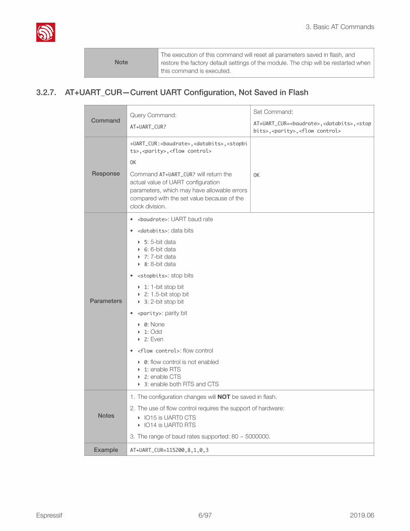
3.2.7. AT+UART_CUR—Current UART Configuration, Not Saved in Flash
NoteThe execution of this command will reset all parameters saved in flash, and restore the factory default settings of the module. The chip will be restarted when this command is executed.
CommandQuery Command:
AT+UART_CUR?
Set Command:
AT+UART_CUR=<baudrate>,<databits>,<stopbits>,<parity>,<flowcontrol>
Response
+UART_CUR:<baudrate>,<databits>,<stopbits>,<parity>,<flowcontrol>
OK
Command AT+UART_CUR? will return the actual value of UART configuration parameters, which may have allowable errors compared with the set value because of the clock division.
OK
Parameters
• <baudrate>: UART baud rate
• <databits>: data bits
‣ 5: 5-bit data ‣ 6: 6-bit data ‣ 7: 7-bit data ‣ 8: 8-bit data
• <stopbits>: stop bits
‣ 1: 1-bit stop bit ‣ 2: 1.5-bit stop bit ‣ 3: 2-bit stop bit
• <parity>: parity bit
‣ 0: None ‣ 1: Odd ‣ 2: Even
• <flowcontrol>: flow control
‣ 0: flow control is not enabled ‣ 1: enable RTS ‣ 2: enable CTS ‣ 3: enable both RTS and CTS
Notes
1. The configuration changes will NOT be saved in flash.
2. The use of flow control requires the support of hardware: ‣ IO15 is UART0 CTS ‣ IO14 is UART0 RTS
3. The range of baud rates supported: 80 ~ 5000000.
Example AT+UART_CUR=115200,8,1,0,3
Espressif ! /!6 97 2019.06

!
3. Basic AT Commands
3.2.8. AT+UART_DEF—Default UART Configuration, Saved in Flash
Command
Query Command:
AT+UART_DEF?
Function:
Read the UART configuration from flash.
Set Command:
AT+UART_DEF=<baudrate>,<databits>,<stopbits>,<parity>,<flowcontrol>
Response+UART_DEF:<baudrate>,<databits>,<stopbits>,<parity>,<flowcontrol>
OK
OK
Parameters
• <baudrate>: UART baud rate • <databits>: data bits
‣ 5: 5-bit data ‣ 6: 6-bit data ‣ 7: 7-bit data ‣ 8: 8-bit data
• <stopbits>: stop bits
‣ 1: 1-bit stop bit ‣ 2: 1.5-bit stop bit ‣ 3: 2-bit stop bit
• <parity>: parity bit
‣ 0: None ‣ 1: Odd ‣ 2: Even
• <flowcontrol>: flow control
‣ 0: flow control is not enabled ‣ 1: enable RTS ‣ 2: enable CTS ‣ 3: enable both RTS and CTS
Notes
1. The configuration changes will be saved in the NVS area, and will still be valid when the chip is powered on again.
2. The use of flow control requires the support of hardware: ‣ IO15 is UART0 CTS ‣ IO14 is UART0 RTS
3. The range of baud rates supported: 80 ~ 5000000.
Example AT+UART_DEF=115200,8,1,0,3
Espressif ! /!7 97 2019.06

!
3. Basic AT Commands
3.2.9. AT+SLEEP—Sets the Sleep Mode
3.2.10. AT+SYSRAM—Checks the Remaining Space of RAM
3.2.11. AT+SYSFLASH—Set User Partitions in Flash *
Set Command AT+SLEEP=<sleepmode>
Response OK
Parameters<sleepmode>:
‣ 0: disable the sleep mode. ‣ 1: Modem-sleep mode.
Example AT+SLEEP=0
Query Command AT+SYSRAM?
Response+SYSRAM:<remainingRAMsize>
OK
Parameters <remainingRAMsize>: remaining space of RAM, unit: byte
ExampleAT+SYSRAM?
+SYSRAM:148408
OK
Command
Query Command:
AT+SYSFLASH?
Function:
Check the user partitions in flash.
Set Command:
AT+SYSFLASH=<operation>,<partition>,<offset>,<length>
Response+SYSFLASH:<partition>,<type>,<subtype>,<addr>,<size>
OK
+SYSFLASH:<length>,<data>
OK
Parameters
<partition>: name of user partition
<type>: type of user partition
<subtype>: subtype of user partition
<addr>: address of user partition
<size>: size of user partition
<operation>:
‣ 0: erase sector ‣ 1: write data into the user partition ‣ 2: read data from the user partition
<partition>: name of user partition
<offset>: offset of user partition
<length>: data length
Espressif ! /!8 97 2019.06

!
3. Basic AT Commands
3.2.12. AT+FS—Filesystem Operations *
Notes
• at_customize.bin has to be downloaded, so that the relevant commands can be used. For more details about at_customize.bin please refer to the ESP32_Customize_Partitions.
• Important things to note when erasing user partitions:
‣ When erasing the targeted user partition in its entirety, parameters <offset> and <length> can be omitted. For example, command AT+SYSFLASH=0,"ble_data" can erase the entire "ble_data" user partition.
‣ If parameters <offset> and <length> are not omitted when erasing the user partition, they have to be 4KB-aligned.
• The introduction to partitions is in ESP-IDF Partition Tables.
Example
// read 100 bytes from the "ble_data" partition offset 0. AT+SYSFLASH=2,"ble_data",0,100
// write 10 bytes to the "ble_data" partition offset 100.AT+SYSFLASH=1,"ble_data",100,10
// erase 8192 bytes from the "ble_data" partition offset 4096.AT+SYSFLASH=0,"ble_data",4096,8192
CommandSet Command:
AT+FS=<type>,<operation>,<filename>,<offset>,<length>
Response OK
Parameters
<type>: only FATFS is currently supported
‣ 0: FATFS
<operation>:
‣ 0: delete file ‣ 1: write file ‣ 2: read file ‣ 3: query the size of the file ‣ 4: list files in a specific directory, only root directory is currently supported
<offset>: offset, for writing and reading operations only
<length>: data length, for writing and reading operations only
Notes
• This function is disabled by default. User needs to set configuration by "make menuconfig" to enable it, and re-compile the ESP32 AT firmware.
• at_customize.bin has to be downloaded, so that the relevant commands can be used. The definitions of user partitions are in esp32-at/at_customize.csv. Please refer to the ESP32_Customize_Partitions for more details.
Espressif ! /!9 97 2019.06

!
3. Basic AT Commands
Example
// delete a file.
AT+FS=0,0,"filename"
// write 10 bytes to offset 100 of a file.
AT+FS=0,1,"filename",100,10
// read 100 bytes from offset 0 of a file.
AT+FS=0,2,"filename",0,100
// list all files in the root directory.
AT+FS=0,4,"."
Espressif ! /!10 97 2019.06
!
3. Basic AT Commands
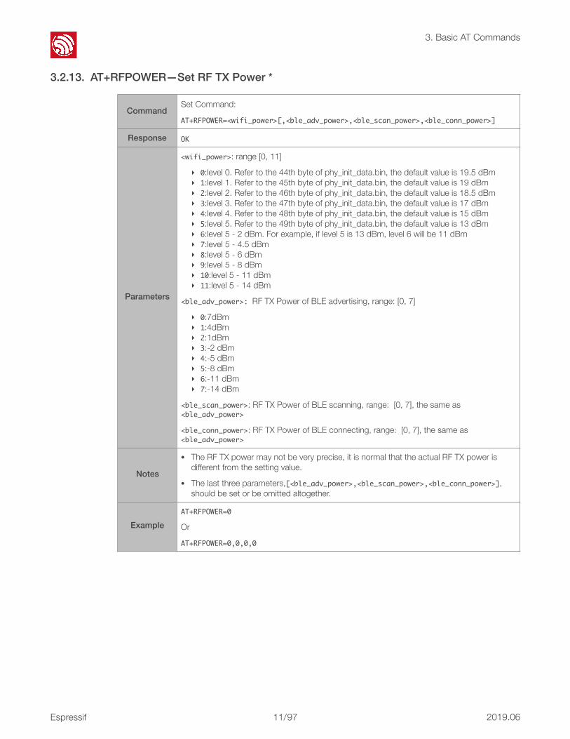
3.2.13. AT+RFPOWER—Set RF TX Power *
CommandSet Command:
AT+RFPOWER=<wifi_power>[,<ble_adv_power>,<ble_scan_power>,<ble_conn_power>]
Response OK
Parameters
<wifi_power>: range [0, 11]
‣ 0:level 0. Refer to the 44th byte of phy_init_data.bin, the default value is 19.5 dBm ‣ 1:level 1. Refer to the 45th byte of phy_init_data.bin, the default value is 19 dBm ‣ 2:level 2. Refer to the 46th byte of phy_init_data.bin, the default value is 18.5 dBm ‣ 3:level 3. Refer to the 47th byte of phy_init_data.bin, the default value is 17 dBm ‣ 4:level 4. Refer to the 48th byte of phy_init_data.bin, the default value is 15 dBm ‣ 5:level 5. Refer to the 49th byte of phy_init_data.bin, the default value is 13 dBm ‣ 6:level 5 - 2 dBm. For example, if level 5 is 13 dBm, level 6 will be 11 dBm ‣ 7:level 5 - 4.5 dBm ‣ 8:level 5 - 6 dBm ‣ 9:level 5 - 8 dBm ‣ 10:level 5 - 11 dBm ‣ 11:level 5 - 14 dBm
<ble_adv_power>:RF TX Power of BLE advertising, range: [0, 7]
‣ 0:7dBm ‣ 1:4dBm ‣ 2:1dBm ‣ 3:-2 dBm ‣ 4:-5 dBm ‣ 5:-8 dBm ‣ 6:-11 dBm ‣ 7:-14 dBm
<ble_scan_power>: RF TX Power of BLE scanning, range: [0, 7], the same as <ble_adv_power>
<ble_conn_power>: RF TX Power of BLE connecting, range: [0, 7], the same as <ble_adv_power>
Notes
• The RF TX power may not be very precise, it is normal that the actual RF TX power is different from the setting value.
• The last three parameters,[<ble_adv_power>,<ble_scan_power>,<ble_conn_power>], should be set or be omitted altogether.
ExampleAT+RFPOWER=0
Or
AT+RFPOWER=0,0,0,0
Espressif ! /!11 97 2019.06

!
4. Wi-Fi AT Commands
4. Wi-Fi AT Commands 4.1. Overview
4.2. Commands 4.2.1. AT+CWMODE—Sets the Wi-Fi Mode (Station/SoftAP/Station+SoftAP)
Commands Description
AT+CWMODE Sets the Wi-Fi mode (STA/AP/STA+AP).
AT+CWJAP Connects to an AP.
AT+CWLAPOPT Sets the configuration of command AT+CWLAP.
AT+CWLAP Lists available APs.
AT+CWQAP Disconnects from the AP.
AT+CWSAP Sets the configuration of the ESP32 SoftAP.
AT+CWLIF Gets the Station IP to which the ESP32 SoftAP is connected.
AT+CWDHCP Enables/disables DHCP.
AT+CWDHCPSSets the IP range of the ESP32 SoftAP DHCP server.
Saves the setting in flash.
AT+CWAUTOCONN Connects to the AP automatically on power-up.
AT+CWSTARTSMART Starts SmartConfig.
AT+CWSTOPSMART Stops SmartConfig.
AT+WPS Enables the WPS function.
AT+CWHOSTNAME Configure the host name of ESP32 station.
AT+MDNS MDNS function
Commands
Test Command:
AT+CWMODE=?
Query Command:
AT+CWMODE?
Function: to query the Wi-Fi mode of ESP32.
Set Command:
AT+CWMODE=<mode>
Function: to set the Wi-Fi mode of ESP32.
Response+CWMODE:<mode>
OK
+CWMODE:<mode>
OKOK
Espressif ! /!12 97 2019.06

!
4. Wi-Fi AT Commands
Parameters
<mode>:
‣ 0: Null mode, Wi-Fi RF will be disabled * ‣ 1: Station mode ‣ 2: SoftAP mode ‣ 3: SoftAP+Station mode
Note The configuration changes will be saved in the NVS area.
Example AT+CWMODE=3
Espressif ! /!13 97 2019.06

!
4. Wi-Fi AT Commands
4.2.2. AT+CWJAP—Connects to an AP
Commands
Query Command:
AT+CWJAP?
Function: to query the AP to which the ESP32 Station is already connected.
Set Command:
AT+CWJAP=<ssid>,<pwd>[,<bssid>]
Function: to set the AP to which the ESP32 Station needs to be connected.
Response+CWJAP:<ssid>,<bssid>,<channel>,<rssi>
OK
OK
or
+CWJAP:<errorcode>
ERROR
Parameters
• <ssid>:a string parameter showing the SSID of the AP.
• <bssid>: the AP's MAC address. • <channel>: channel • <rssi>: signal strength
• <ssid>: the SSID of the target AP. • <pwd>: password, MAX: 64-byte ASCII. • [<bssid>](optional parameter): the target
AP's MAC address, used when multiple APs have the same SSID.
• <errorcode>: (for reference only) ‣ 1: connection timeout. ‣ 2: wrong password. ‣ 3: cannot find the target AP. ‣ 4: connection failed. ‣ others: unknown error occurred.
Escape character syntax is needed if SSID or password contains any special characters, such as, or " or \.
Messages
// If ESP32 station connects to an AP, it will prompt messages:
WIFI CONNECTED
WIFI GOT IP
// If the WiFi connection ends, it will prompt messages:
WIFI DISCONNECT
Note• The configuration changes will be saved in the NVS area.
• This command requires Station mode to be active.
Examples
AT+CWJAP="abc","0123456789"
For example, if the target AP's SSID is "ab\,c" and the password is "0123456789"\", the command isas follows:
AT+CWJAP="ab\\\,c","0123456789\"\\"
If multiple APs have the same SSID as "abc", the target AP can be found by BSSID:
AT+CWJAP="abc","0123456789","ca:d7:19:d8:a6:44"
Espressif ! /!14 97 2019.06

!
4. Wi-Fi AT Commands
4.2.3. AT+CWLAPOPT—Sets the Configuration for the Command AT+CWLAP
Set Command AT+CWLAPOPT=<sort_enable>,<mask>
Response OK
Parameters
• <sort_enable>: determines whether the result of command AT+CWLAP will be listed according to RSSI:
‣ 0: the result is not ordered according to RSSI. ‣ 1: the result is ordered according to RSSI.
• <mask>: determines the parameters shown in the result of AT+CWLAP; 0 means not showing the parameter corresponding to the bit, and 1 means showing it.
‣ bit0: determines whether <ecn> will be shown in the result of AT+CWLAP. ‣ bit1: determines whether <ssid> will be shown in the result of AT+CWLAP. ‣ bit2: determines whether <rssi> will be shown in the result of AT+CWLAP. ‣ bit3: determines whether <mac> will be shown in the result of AT+CWLAP. ‣ bit4: determines whether <channel> will be shown in the result of AT+CWLAP.
Example
AT+CWLAPOPT=1,31
The first parameter is 1, meaning that the result of the command AT+CWLAP will be ordered according to RSSI;
The second parameter is 31, namely 0x1F, meaning that the corresponding bits of <mask> are set to 1. All parameters will be shown in the result of AT+CWLAP.
Espressif ! /!15 97 2019.06

!
4. Wi-Fi AT Commands
4.2.4. AT+CWLAP—Lists the Available APs
4.2.5. AT+CWQAP—Disconnects from the AP
Commands
Set Command:
AT+CWLAP=<ssid>[,<mac>,<channel>]
Function: to query the APs with specific SSID and MAC on a specific channel.
Execute Command:
AT+CWLAP
Function: to list all available APs.
Response+CWLAP:<ecn>,<ssid>,<rssi>,<mac>,<channel>
OK
+CWLAP:<ecn>,<ssid>,<rssi>,<mac>,<channel>
OK
Parameters
• <ecn>: encryption method.
‣ 0: OPEN ‣ 1: WEP ‣ 2: WPA_PSK ‣ 3: WPA2_PSK ‣ 4: WPA_WPA2_PSK ‣ 5: WPA2_Enterprise (AT can NOT connect to WPA2_Enterprise AP for now.)
• <ssid>: string parameter, SSID of the AP. • <rssi>: signal strength. • <mac>: string parameter, MAC address of the AP.
Examples
AT+CWLAP="Wi-Fi","ca:d7:19:d8:a6:44",6
or search for APs with a designated SSID:
AT+CWLAP="Wi-Fi"
Execute Command AT+CWQAP
Response OK
Parameters -
Espressif ! /!16 97 2019.06
!
4. Wi-Fi AT Commands
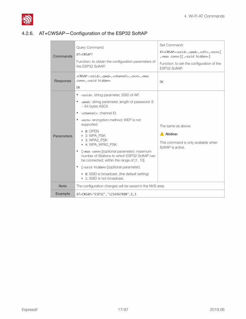
4.2.6. AT+CWSAP—Configuration of the ESP32 SoftAP
Commands
Query Command:
AT+CWSAP?
Function: to obtain the configuration parameters of the ESP32 SoftAP.
Set Command:
AT+CWSAP=<ssid>,<pwd>,<chl>,<ecn>[,<maxconn>][,<ssidhidden>]
Function: to set the configuration of the ESP32 SoftAP.
Response+CWSAP:<ssid>,<pwd>,<channel>,<ecn>,<maxconn>,<ssidhidden>
OK
OK
Parameters
• <ssid>: string parameter, SSID of AP. • <pwd>: string parameter, length of password: 8
~ 64 bytes ASCII. • <channel>: channel ID. • <ecn>: encryption method; WEP is not
supported.
‣ 0: OPEN ‣ 2: WPA_PSK ‣ 3: WPA2_PSK ‣ 4: WPA_WPA2_PSK
• [<maxconn>](optional parameter): maximum number of Stations to which ESP32 SoftAP can be connected; within the range of [1, 10].
• [<ssidhidden>](optional parameter):
‣ 0: SSID is broadcast. (the default setting) ‣ 1: SSID is not broadcast.
The same as above.
⚠ Notice:
This command is only available when SoftAP is active.
Note The configuration changes will be saved in the NVS area.
Example AT+CWSAP="ESP32","1234567890",5,3
Espressif ! /!17 97 2019.06
!
4. Wi-Fi AT Commands
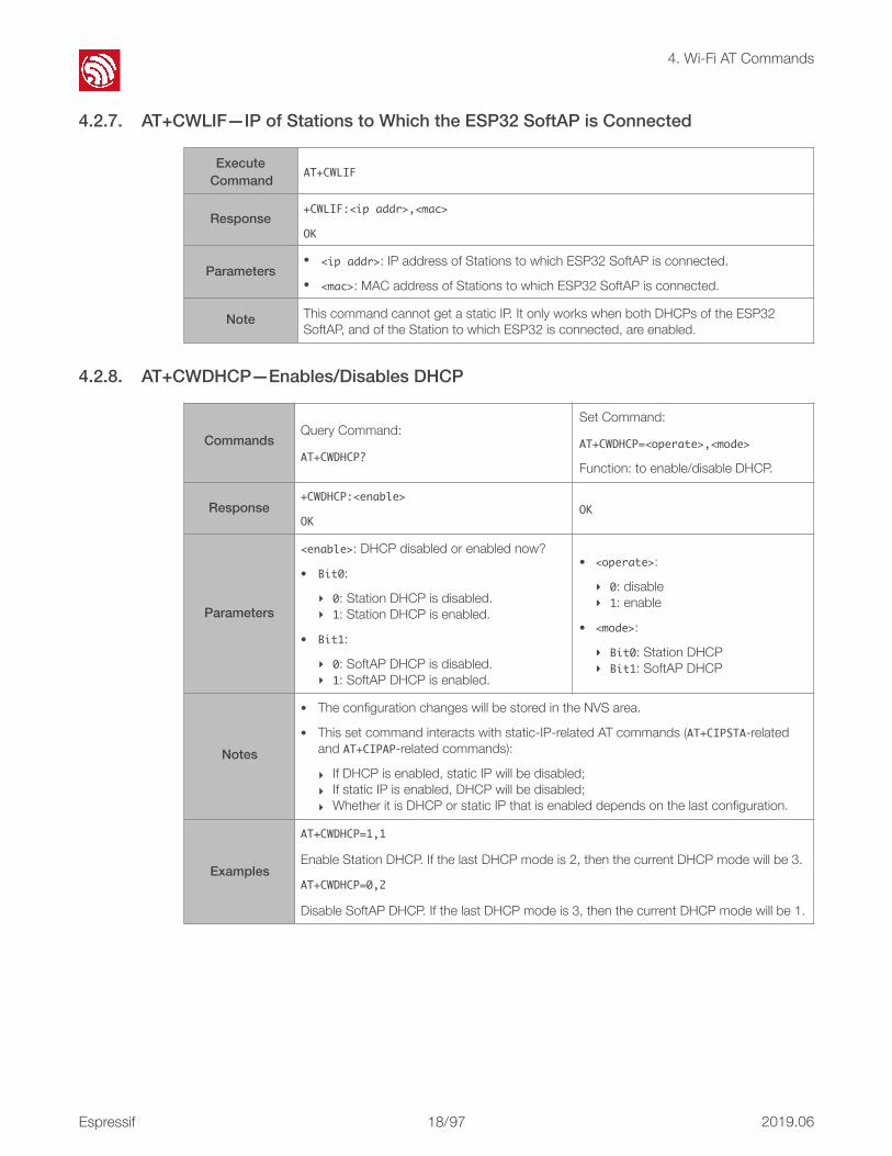
4.2.7. AT+CWLIF—IP of Stations to Which the ESP32 SoftAP is Connected
4.2.8. AT+CWDHCP—Enables/Disables DHCP
Execute Command AT+CWLIF
Response+CWLIF:<ipaddr>,<mac>
OK
Parameters• <ipaddr>: IP address of Stations to which ESP32 SoftAP is connected. • <mac>: MAC address of Stations to which ESP32 SoftAP is connected.
Note This command cannot get a static IP. It only works when both DHCPs of the ESP32 SoftAP, and of the Station to which ESP32 is connected, are enabled.
CommandsQuery Command:
AT+CWDHCP?
Set Command:
AT+CWDHCP=<operate>,<mode>
Function: to enable/disable DHCP.
Response+CWDHCP:<enable>
OKOK
Parameters
<enable>: DHCP disabled or enabled now?
• Bit0:
‣ 0: Station DHCP is disabled. ‣ 1: Station DHCP is enabled.
• Bit1:
‣ 0: SoftAP DHCP is disabled. ‣ 1: SoftAP DHCP is enabled.
• <operate>:
‣ 0: disable ‣ 1: enable
• <mode>:
‣ Bit0: Station DHCP ‣ Bit1: SoftAP DHCP
Notes
• The configuration changes will be stored in the NVS area.
• This set command interacts with static-IP-related AT commands (AT+CIPSTA-relatedand AT+CIPAP-related commands):
‣ If DHCP is enabled, static IP will be disabled; ‣ If static IP is enabled, DHCP will be disabled; ‣ Whether it is DHCP or static IP that is enabled depends on the last configuration.
Examples
AT+CWDHCP=1,1
Enable Station DHCP. If the last DHCP mode is 2, then the current DHCP mode will be 3.
AT+CWDHCP=0,2
Disable SoftAP DHCP. If the last DHCP mode is 3, then the current DHCP mode will be 1.
Espressif ! /!18 97 2019.06

!
4. Wi-Fi AT Commands
4.2.9. AT+CWDHCPS—Sets the IP Address Allocated by ESP32 SoftAP DHCP (The configuration is saved in Flash.)
4.2.10. AT+CWAUTOCONN—Auto-Connects to the AP or Not
Commands
Query Command:
AT+CWDHCPS?
Set Command:
AT+CWDHCPS=<enable>,<leasetime>,<startIP>,<endIP>
Function: sets the IP address range of the ESP32 SoftAP DHCP server.
Response+CWDHCPS:<leasetime>,<startIP>,<endIP>
OK
OK
Parameters
• <enable>:
‣ 0: Disable the settings and use the default IP range. ‣ 1: Enable setting the IP range, and the parameters below have to be set.
• <leasetime>: lease time, unit: minute, range [1, 2880].
• <startIP>: start IP of the IP range that can be obtained from ESP32 SoftAP DHCP server.
• <endIP>: end IP of the IP range that can be obtained from ESP32 SoftAP DHCP server.
Notes
• The configuration changes will be saved in the NVS area.
• This AT command can only be called when ESP32 runs as SoftAP, and when DHCP is enabled. The IP address should be in the same network segment as the IP address of ESP32 SoftAP.
Examples
AT+CWDHCPS=1,3,"192.168.4.10","192.168.4.15"
or
AT+CWDHCPS=0//DisablethesettingsandusethedefaultIPrange.
Set Command AT+CWAUTOCONN=<enable>
Response OK
Parameters
<enable>:
‣ 0: does NOT auto-connect to AP on power-up. ‣ 1: connects to AP automatically on power-up.
The ESP32 Station connects to the AP automatically on power-up by default.
Note The configuration changes will be saved in the NVS area.
Example AT+CWAUTOCONN=1
Espressif ! /!19 97 2019.06

!
4. Wi-Fi AT Commands
4.2.11. AT+CWSTARTSMART—Starts SmartConfig
4.2.12. AT+CWSTOPSMART—Stops SmartConfig
Commands
Set Command:
AT+CWSTARTSMART=<type>
Function: to start SmartConfig of a designated type.
Set Command:
AT+CWSTARTSMART
Function: enable ESP-TOUCH+AirKiss SmartConfig.
Response OK OK
Parameters
<type>:
‣ 1: ESP-TOUCH ‣ 2: AirKiss ‣ 3: ESP-TOUCH+AirKiss
none
Messages
When smartconfig starts, it will prompt messages as below:
smartconfig type: <type> // AIRKISS, ESPTOUCH or UNKNOWN
Smart get wifi info // got SSID and password
ssid:<AP's SSID>
password:<AP's password>
// ESP32 will try to connect to the AP
WIFI CONNECTED
WIFI GOT IP
smartconfig connected wifi // if the connection failed, it will prompt "smartconfig connect fail"
Notes
• For details on SmartConfig please see ESP-TOUCH User Guide.
• SmartConfig is only available in the ESP32 Station mode.
• The message Smartgetwifiinfo means that SmartConfig has successfully acquired the AP information. ESP32 will try to connect to the target AP.
• Message smartconfigconnectedwifi is printed if the connection is successful.
• Use command AT+CWSTOPSMART to stop SmartConfig before running other commands. Please make sure that you do not execute other commands during SmartConfig.
ExampleAT+CWMODE=1
AT+CWSTARTSMART=3
Execute Command AT+CWSTOPSMART
Response OK
Parameters -
NoteIrrespective of whether SmartConfig succeeds or not, before executing any other AT commands, please always call AT+CWSTOPSMART to release the internal memory taken up by SmartConfig.
Example AT+CWSTOPSMART
Espressif ! /!20 97 2019.06

!
4. Wi-Fi AT Commands
4.2.13. AT+WPS—Enables the WPS Function
4.2.14. AT+CWHOSTNAME—Configures the Host Name of ESP32 Station *
4.2.15. AT+MDNS—Configures the MDNS Function *
Set Command AT+WPS=<enable>
ResponseOK
or
ERROR
Parameters
<enable>:
‣ 1: enable WPS/Wi-Fi Protected Setup (implemented by PBC/Push Button Configuration).
‣ 0: disable WPS (implemented by PBC).
Notes• WPS must be used when the ESP32 Station is enabled. • WPS does not support WEP/Wired-Equivalent Privacy encryption.
ExampleAT+CWMODE=1
AT+WPS=1
Commands
Query Command:
AT+CWHOSTNAME?
Function: Checks the host name of ESP32 Station.
Set Command:
AT+CWHOSTNAME=<hostname>
Function: Sets the host name of ESP32 Station.
Response
+CWHOSTNAME:<hostname>
OK
If the station mode is not enabled, the command will return:
+CWHOSTNAME:<null>
OK
OK
If the station mode is not enabled, the command will return:
ERROR
Parameters <hostname>: the host name of the ESP32 Station, maximum length: 32 bytes
Notes• The configuration changes are not saved in the flash.
• The default host name of the ESP32 Station is ESP_XXXXXX; XXXXXX is the lower 3 bytes of the MAC address, for example, +CWHOSTNAME:<ESP_A378DA>.
ExampleAT+CWMODE=3
AT+CWHOSTNAME="my_test"
Set Command AT+MDNS=<enable>[,<hostname>,<service_name>,<port>]
Response OK
Espressif ! /!21 97 2019.06

!
4. Wi-Fi AT Commands
Parameters
• <enable>:
‣ 1: enables the MDNS function; the following three parameters need to be set.
‣ 0: disables the MDNS function; the following three parameters need not to be set.
• <hostname>: MDNS host name
• <service_name>: MDNS service name, it should start with "_"
• <port>: MDNS port
Notes • Please do not use other special characters (such as.) for <hostname> and <service_name>.
ExampleAT+MDNS=1,"espressif","_iot",8080
OrAT+MDNS=0
Espressif ! /!22 97 2019.06

!
5. TCP/IP-Related AT Commands
5. TCP/IP-Related AT Commands 5.1. Overview
Commands Description
AT+CIPSTATUS Gets the connection status.
AT+CIPDOMAIN DNS function.
AT+CIPDNS Sets user-defined DNS server.
AT+CIPSTAMAC Sets the MAC address of ESP32 Station.
AT+CIPAPMAC Sets the MAC address of ESP32 SoftAP.
AT+CIPSTA Sets the IP address of ESP32 Station.
AT+CIPAP Sets the IP address of ESP32 SoftAP.
AT+CIPSTART Establishes TCP connection, UDP transmission or SSL connection.
AT+CIPSSLCCONF Sets configuration of SSL client
AT+CIPSEND Sends data.
AT+CIPSENDEXSends data when length of data is <length>, or when \0 appears in the data.
AT+CIPCLOSE Closes TCP/UDP/SSL connection.
AT+CIFSR Gets the local IP address.
AT+CIPMUX Configures the multiple connections mode.
AT+CIPSERVER Deletes/Creates TCP or SSL server.
AT+CIPSERVERMAXCONN Set the maximum connections that server allows
AT+CIPMODE Configures the transmission mode.
AT+SAVETRANSLINK Saves the transparent transmission link in flash.
AT+CIPSTO Sets timeout when ESP32 runs as a TCP server.
AT+CIUPDATE Updates the software through Wi-Fi.
AT+CIPDINFO Shows remote IP and remote port with +IPD.
AT+CIPSNTPCFG Configures the time domain and SNTP server.
AT+CIPSNTPTIME Queries the SNTP time.
AT+PING Ping packets
Espressif ! /!23 97 2019.06

!
5. TCP/IP-Related AT Commands
5.2. Commands 5.2.1. AT+CIPSTATUS—Gets the Connection Status
5.2.2. AT+CIPDOMAIN—DNS Function
5.2.3. AT+CIPDNS—Sets User-defined DNS Servers; Configuration Saved in the Flash
Execute Command AT+CIPSTATUS
ResponseSTATUS:<stat>
+CIPSTATUS:<linkID>,<type>,<remoteIP>,<remoteport>,<localport>,<tetype>
Parameters
• <stat>: status of the ESP32 Station interface.
‣ 2: The ESP32 Station is connected to an AP and its IP is obtained. ‣ 3: The ESP32 Station has created a TCP or UDP transmission. ‣ 4: The TCP or UDP transmission of ESP32 Station is disconnected. ‣ 5: The ESP32 Station does NOT connect to an AP.
• <linkID>: ID of the connection (0~4), used for multiple connections.
• <type>: string parameter, "TCP" or "UDP".
• <remoteIP>: string parameter indicating the remote IP address.
• <remoteport>: the remote port number.
• <localport>: ESP32 local port number.
• <tetype>:
‣ 0: ESP32 runs as a client. ‣ 1: ESP32 runs as a server.
Execute Command AT+CIPDOMAIN=<domainname>
Response +CIPDOMAIN:<IPaddress>
Parameter <domainname>: the domain name.
ExampleAT+CWMODE=1//setStationmode
AT+CWJAP="SSID","password"//accesstotheinternet
AT+CIPDOMAIN="iot.espressif.cn"//DNSfunction
Commands
Query Command:
AT+CIPDNS?
Function: Get the user-defined DNS servers which saved in flash.
Set Command:
AT+CIPDNS=<enable>[,<DNSserver0>,<DNSserver1>]
Function: Set user-defined DNS servers.
Response
+CIPDNS:<DNSserver0>
[+CIPDNS:<DNSserver1>]
OK
OK
Espressif ! /!24 97 2019.06

!
5. TCP/IP-Related AT Commands
5.2.4. AT+CIPSTAMAC—Sets the MAC Address of the ESP32 Station
5.2.5. AT+CIPAPMAC—Sets the MAC Address of the ESP32 SoftAP
Parameters
• <enable>:
‣ 0: disable to use a user-defined DNS server;‣ 1: enable to use a user-defined DNS server.
• <DNSserver0>: optional parameter indicating the first DNS server;
• <DNSserver1>: optional parameter indicating the second DNS serve.
Example AT+CIPDNS=1,"208.67.220.220"
Note
• This configuration will be saved in flash.
• For command: AT+CIPDNS=0 (disable to use user-defined DNS servers), "208.67.222.222" will be used as DNS server by default. And the DNS server may change according to the configuration of the router which the chip connected to.
• For command: AT+CIPDNS=1 (enable to use user-defined DNS servers, but the <DNS server> parameters are not set), servers "208.67.222.222"will be used as DNS server by default.
• If users set two DNS servers with this command, please note that these two DNS servers should not be the same.
Commands
Query Command:
AT+CIPSTAMAC?
Function: to obtain the MAC address of the ESP32 Station.
Set Command:
AT+CIPSTAMAC=<mac>
Function: to set the MAC address of the ESP32 Station.
Response+CIPSTAMAC:<mac>
OKOK
Parameters <mac>: string parameter, MAC address of the ESP Station.
Notes
• The configuration changes will be saved in the NVS area.
• The MAC address of ESP32 SoftAP is different from that of the ESP32 Station. Please make sure that you do not set the same MAC address for both of them.
• Bit 0 of the ESP32 MAC address CANNOT be 1. For example, a MAC address can be "1a:…" but not "15:…".
• FF:FF:FF:FF:FF:FF and 00:00:00:00:00:00 are invalid MAC and cannot be set.
Example AT+CIPSTAMAC="1a:fe:35:98:d3:7b"
Commands
Query Command:
AT+CIPAPMAC?
Function: to obtain the MAC address of the ESP32 SoftAP.
Set Command:
AT+CIPAPMAC=<mac>
Function: to set the MAC address of the ESP32 SoftAP.
Response+CIPAPMAC:<mac>
OKOK
Espressif ! /!25 97 2019.06

!
5. TCP/IP-Related AT Commands
5.2.6. AT+CIPSTA—Sets the IP Address of the ESP32 Station
5.2.7. AT+CIPAP—Sets the IP Address of the ESP32 SoftAP
Parameters <mac>: string parameter, MAC address of ESP32 SoftAP.
Notes
• The configuration changes will be saved in the NVS area. • The MAC address of ESP32 SoftAP is different from that of the ESP32 Station. Please
make sure you do not set the same MAC address for both of them. • Bit 0 of the ESP32 MAC address CANNOT be 1. For example, a MAC address can be "18:
…" but not "15:…". • FF:FF:FF:FF:FF:FF and 00:00:00:00:00:00 are invalid MAC and cannot be set.
Example AT+CIPAPMAC="18:fe:36:97:d5:7b"
Commands
Query Command:
AT+CIPSTA?
Function: to obtain the IP address of the ESP32 Station.
Set Command:
AT+CIPSTA=<ip>[,<gateway>,<netmask>]
Function: to set the IP address of the ESP32 Station.
Response+CIPSTA:<ip>
OKOK
Parameters⚠ Notice:
Only when the ESP32 Station is connected to an AP can its IP address be queried.
• <ip>: string parameter, the IP address of the ESP32 Station.
• [<gateway>]: gateway.
• [<netmask>]: netmask.
Notes
• The configuration changes will be saved in the NVS area.
• The set command interacts with DHCP-related AT commands (AT+CWDHCP-relatedcommands):
‣ If static IP is enabled, DHCP will be disabled; ‣ If DHCP is enabled, static IP will be disabled; ‣ Whether it is DHCP or static IP that is enabled depends on the last configuration.
Example AT+CIPSTA="192.168.6.100","192.168.6.1","255.255.255.0"
Commands
Query Command:
AT+CIPAP?
Function: to obtain the IP address of the ESP32 SoftAP.
Set Command:
AT+CIPAP=<ip>[,<gateway>,<netmask>]
Function: to set the IP address of the ESP32 SoftAP.
Response+CIPAP:<ip>,<gateway>,<netmask>
OKOK
Parameters
• <ip>: string parameter, the IP address of the ESP32 SoftAP.
• [<gateway>]: gateway.
• [<netmask>]: netmask.
Espressif ! /!26 97 2019.06

!
5. TCP/IP-Related AT Commands
5.2.8. AT+CIPSTART—Establishes TCP Connection, UDP Transmission or SSL Connection
Notes
• The configuration changes will be saved in the NVS area.
• Currently, ESP32 only supports class C IP addresses.
• The set command interacts with DHCP-related AT commands (AT+CWDHCP-relatedcommands):
‣ If static IP is enabled, DHCP will be disabled; ‣ If DHCP is enabled, static IP will be disabled; ‣ Whether it is DHCP or static IP that is enabled depends on the last configuration.
Example AT+CIPAP="192.168.5.1","192.168.5.1","255.255.255.0"
Establish TCP Connection
Set Command
Single TCP connection (AT+CIPMUX=0):
AT+CIPSTART=<type>,<remoteIP>,<remoteport>[,<TCPkeepalive>]
Multiple TCP Connections (AT+CIPMUX=1):
AT+CIPSTART=<linkID>,<type>,<remoteIP>,<remoteport>[,<TCPkeepalive>]
Response OK
Parameters
• <linkID>: ID of network connection (0~4), used for multiple connections.
• <type>: string parameter indicating the connection type: "TCP", "UDP"or "SSL".
• <remoteIP>: string parameter indicating the remote IP address.
• <remoteport>: remote port number.
• [<TCPkeepalive>] (optional parameter): detection time interval when TCP is kept alive. This function is disabled by default. Users are recommended to enable this function when establishing a TCP connection.
‣ 0: disable TCP keep-alive. ‣ 1~7200: detection time interval, unit: second(s).
Messages
// If the TCP connection is established, a message appears as below:
[<link ID>,] CONNECT
// If the TCP connection ends, a message appears as below:
[<link ID>,] CLOSED
Note Users are recommended to enable this function when establishing a TCP connection.
ExamplesAT+CIPSTART="TCP","iot.espressif.cn",8000
AT+CIPSTART="TCP","192.168.101.110",1000
For more information please see Chapter 9: AT Command Examples.
Establish UDP Transmission
Set Command
Single connection (AT+CIPMUX=0):
AT+CIPSTART=<type>,<remoteIP>,<remoteport>[,<UDPlocalport>,<UDPmode>]
Multiple connections (AT+CIPMUX=1):
AT+CIPSTART=<linkID>,<type>,<remoteIP>,<remoteport>[,<UDPlocalport>,<UDPmode>]
Espressif ! /!27 97 2019.06

!
5. TCP/IP-Related AT Commands
Response OK
Parameters
• <linkID>: ID of network connection (0~4), used for multiple connections. • <type>: string parameter indicating the connection type: "TCP", "UDP"or "SSL". • <remoteIP>: string parameter indicating the remote IP address. • <remoteport>: remote port number. • [<UDPlocalport>]: optional. It is the UDP port of ESP32. • [<UDPmode>] (optional parameter): the entity of UDP transmission. For UDP transparent
transmission, the value of this parameter has to be 0.
‣ 0: the destination peer entity of UDP will not change; this is the default setting. ‣ 1: the destination peer entity of UDP will change once. ‣ 2: the destination peer entity of UDP is allowed to change.
⚠ Notice:
To use <UDPmode> , <UDPlocalport> must be set first.
Messages
// If the UDP transmission is established, a message appears as below
[<link ID>,] CONNECT
// If the UDP transmission ends, a message appears as below
[<link ID>,] CLOSED
ExampleAT+CIPSTART="UDP","192.168.101.110",1000,1002,2
For more information please see Chapter 9: AT Command Examples.
Establish SSL Connection
Set Command AT+CIPSTART=[<linkID>,]<type>,<remoteIP>,<remoteport>[,<TCPkeepalive>]
Response OK
Parameters
• <linkID>: ID of network connection (0~4), used for multiple connections. • <type>: string parameter indicating the connection type: "TCP", "UDP"or "SSL". • <remoteIP>: string parameter indicating the remote IP address. • <remoteport>: the remote port number. • [<TCPkeepalive>] (optional parameter): detection time interval when TCP is kept alive.
This function is disabled by default. Users are recommended to enable this function when establishing a TCP
‣ 0: disable the TCP keep-alive function. ‣ 1~7200: detection time interval, unit: second (s).
Messages
// If the SSL connection is established, a message appears as below
[<link ID>,] CONNECT
// If the SSL connection ends, a message appears as below
[<link ID>,] CLOSED
Espressif ! /!28 97 2019.06

!
5. TCP/IP-Related AT Commands
5.2.9. AT+CIPSSLCCONF—Set Configuration of SSL Client *
Notes• SSL connection needs much memory. Lack of available memory may cause system
reboot.
• Users are recommended to enable this function when establishing a TCP connection.
Example AT+CIPSTART="SSL","iot.espressif.cn",8443
Set Command
1. For single connection: (AT+CIPMUX=0) AT+CIPSSLCCONF=<type>,<cert_key_ID>,<CA_ID>
2. For multiple connections: (AT+CIPMUX=1) AT+CIPSSLCCONF=<linkID>,<type>,<cert_key_ID>,<CA_ID>
Response OK
Parameters
• [<link_id>]: ID of the connection (0~4) for multiple connections. If it is omitted in multi-connections mode, then the configuration will take effect on all connections.
• <type>:
‣ 0: no authentication ‣ 1: loading cert and private key for the authentication server may request ‣ 2: loading CA to authenticate server ‣ 3: bi-directional authentication, both SSL server and client will authenticate certificate of
each other
• <cert_key_ID>: The ID of the certificate, starting from 0. ESP32 AT supports multiple certificates. On how to generate the bin file, please refer to PKI Bin in esp32-at/tools/readme.md.
• <CA_ID>: The CA ID that starts from 0. ESP32 AT supports multiple certificates. On how to generate the bin file, please refer to PKI Bin in esp32-at/tools/readme.md.
Note
• Please call this command before establishing the SSL connection, if it is needed.
• This configuration will be saved in the NVS area of flash. And if a SSL connection is saved in flash by command AT+SAVETRANSLINK, the SSL connection will be established according to this configuration in next start-up.
ExampleAT+CIPMUX=1// enable multiple connections
AT+CIPSSLCCONF=1,3,0,0// to set the NO.1 link, loading certificates (with ID 0) for authentication.
Espressif ! /!29 97 2019.06

!
5. TCP/IP-Related AT Commands
5.2.10. AT+CIPSEND—Sends Data
Commands
Set Command:
1. For single connection: (AT+CIPMUX=0) AT+CIPSEND=<length>
2. For multiple connections: (AT+CIPMUX=1)
AT+CIPSEND=<linkID>,<length>
3. Remote IP and ports can be set in UDP transmission:
AT+CIPSEND=[<linkID>,]<length>[,<remoteIP>,<remoteport>]
Function: to configure the data length in normal transmission mode.
Execute Command:
AT+CIPSEND
Function: to start sending data in transparent transmission mode.
Response
Send data of designated length.
Wrap return > after the set command. Begin receiving serial data. When the requirement of data length is met, the transmission of data starts.
If the connection cannot be established or gets disrupted during data transmission, the system returns:
ERROR
If data is transmitted successfully, the system returns:
SENDOK
Otherwise, the system returns:
SENDFAIL
Wrap return > after executing this command.
After entering the transparent transmission, the data will be sent every 2048 bytes or every 20ms.
When a single packet containing +++ is received, ESP32 returns to normal command mode. Please wait for at least one second before sending the next AT command.
This command can only be used in transparent transmission mode which requires single connection.
For UDP transparent transmission, the value of <UDPmode>has to be 0 when using AT+CIPSTART.
Parameters
• <linkID>: ID of the connection (0~4), for multiple connections.
• <length>: data length, MAX: 2048 bytes.
• [<remoteIP>]: remote IP can be set in UDP transmission.
• [<remoteport>]: remote port can be set in UDP transmission.
-
Example For more information please see Chapter 9: AT Command Examples.
Espressif ! /!30 97 2019.06

!
5. TCP/IP-Related AT Commands
5.2.11. AT+CIPSENDEX—Sends Data
5.2.12. AT+CIPCLOSE—Closes TCP/UDP/SSL Connection
Commands
Set Command:
1. Single connection: (+CIPMUX=0)
AT+CIPSENDEX=<length>
2. Multiple connections: (+CIPMUX=1)
AT+CIPSENDEX=<linkID>,<length>
3. Remote IP and ports can be set in UDP transmission:
AT+CIPSENDEX=[<linkID>,]<length>[,<remoteIP>,<remoteport>]
Function: to configure the data length in normal transmission mode.
Response
Send data of designated length.
Wrap return > after the set command. Begin receiving serial data. When the requirement of data length, determined by <length>, is met, or when \0appears in the data, the transmission starts.
If connection cannot be established or gets disconnected during transmission, the system returns:
ERROR
If data are successfully transmitted, the system returns:
SENDOK
Otherwise, the system returns:
SENDFAIL
Parameters
• <linkID>: ID of the connection (0~4), for multiple connections.
• <length>: data length, MAX: 2048 bytes.
• When the requirement of data length, determined by <length>, is met, or when \0 appears, the transmission of data starts. Go back to the normal command mode and wait for the next AT command.
• When sending \0, please send it as \\0.
CommandsSet Command (for multiple connections):
AT+CIPCLOSE=<linkID>
Function: to close TCP/UDP connection.
Execute Command (for single connection):
AT+CIPCLOSE
Response OK
Parameters <linkID>: ID number of connections to be closed; when ID=5, all connections will be closed. -
Messages// When connection ends, it will prompt message as below
[<link ID>,] CLOSED
Espressif ! /!31 97 2019.06

!
5. TCP/IP-Related AT Commands
5.2.13. AT+CIFSR—Gets the Local IP Address
5.2.14. AT+CIPMUX—Enables/Disables Multiple Connections
Execute Command AT+CIFSR
Response
+CIFSR:APIP,<SoftAPIPaddress>
+CIFSR:APMAC,<SoftAPMACaddress>
+CIFSR:STAIP,<StationIPaddress>
+CIFSR:STAMAC,<StationMACaddress>
OK
Parameters
<IPaddress>:
IP address of the ESP32 SoftAP;
IP address of the ESP32 Station.
<MACaddress>:
MAC address of the ESP32 SoftAP;
MAC address of the ESP32 Station.
Notes Only when the ESP32 Station is connected to an AP can the Station IP be queried.
CommandsQuery Command:
AT+CIPMUX?
Set Command:
AT+CIPMUX=<mode>
Function: to set the connection type.
Response+CIPMUX:<mode>
OKOK
Parameters<mode>:
‣ 0: single connection ‣ 1: multiple connections
Notes
• The default mode is single connection mode.
• Multiple connections can only be set when transparent transmission is disabled (AT+CIPMODE=0).
• This mode can only be changed after all connections are disconnected.
• If the TCP server is running, it must be deleted (AT+CIPSERVER=0) before the single connection mode is activated.
Example AT+CIPMUX=1
Espressif ! /!32 97 2019.06

!
5. TCP/IP-Related AT Commands
5.2.15. AT+CIPSERVER—Deletes/Creates TCP or SSL Server *
5.2.16. AT+CIPSERVERMAXCONN—Set the Maximum Connections Allowed by Server *
Command
Query Command:
AT+CIPSERVER?
Function: to obtain information about the server mode.
Set Command:
AT+CIPSERVER=<mode>[,<port>][,<SSL>,<SSLCAenable>]
Function: to set a TCP or SSL server.
Response+CIPSERVER:<mode>,<port>,<SSL>,<SSLCAenable>
OK
OK
Parameters
<mode>:
‣ 0: delete server. ‣ 1: create server.
<port> (optional parameter): port number; 333 by default.
[<SSL>] (optional parameter): string "SSL", to set an SSL server
[<SSLCAenable>] (optional parameter):
‣ 0: disable CA. ‣ 1: enable CA.
Notes
• A server can only be created when multiple connections are activated (AT+CIPMUX=1).
• Only one server is allowed to be created.
• A server monitor will be automatically created when the server is created.
• Connecting of a client to the ESP server will take up one connection. The connection will be assigned an ID.
Messages
// If a connection is established, a message appears as below:
[<link ID>,] CONNECT
// If a connection ends, a message appears as below:
[<link ID>,] CLOSED
Example
• To create a TCP server: AT+CIPMUX=1
AT+CIPSERVER=1,80
• To create an SSL server: AT+CIPMUX=1
AT+CIPSERVER=1,443,"SSL",1
Commands
Query Command:
AT+CIPSERVERMAXCONN?
Function: obtain the maximum number of clients allowed to connect to the TCP or SSL server.
Set Command:
AT+CIPSERVERMAXCONN=<num>
Function: set the maximum number of clients allowed to connect to the TCP or SSL server.
Espressif ! /!33 97 2019.06

!
5. TCP/IP-Related AT Commands
5.2.17. AT+CIPMODE—Configures the Transmission Mode
Response+CIPSERVERMAXCONN:<num>
OKOK
Parameters <num>: the maximum number of clients allowed to connect to the TCP or SSL server, range: [1, 5]
Notes To set this configuration, you should call the command AT+CIPSERVERMAXCONN=<num>before creating a server.
ExampleAT+CIPMUX=1
AT+CIPSERVERMAXCONN=2
AT+CIPSERVER=1,80
Commands
Query Command:
AT+CIPMODE?
Function: to obtain information about transmission mode.
Set Command:
AT+CIPMODE=<mode>
Function: to set the transmission mode.
Response+CIPMODE:<mode>
OKOK
Parameters
<mode>:
‣ 0: normal transmission mode. ‣ 1: UART-Wi-Fi passthrough mode (transparent transmission), which can only be enabled
in TCP/SSL single connection mode or in UDP mode when the remote IP and port do not change.
Notes
• The configuration changes will NOT be saved in flash.
• During the UART-Wi-Fi passthrough transmission, if the TCP connection breaks, ESP32 will keep trying to reconnect until +++ is input to exit the transmission. If it is a normal TCP transmission and the TCP connection breaks, ESP32 will give a prompt and will not attempt to reconnect.
• The UART-Wi-Fi passthrough mode and the BLE commands cannot be used together, so before enabling UART-WiFi passthrough mode, please ensure that the BLE commands are not enabled (AT+BLEINIT=0).
Example AT+CIPMODE=1
Espressif ! /!34 97 2019.06

!
5. TCP/IP-Related AT Commands
5.2.18. AT+SAVETRANSLINK—Saves the Transparent Transmission Link in Flash
Save TCP Single Connection in Flash
Set Command
AT+SAVETRANSLINK=<mode>,<remoteIPordomainname>,<remoteport>[,<type>,<TCPkeepalive>]
Response OK
Parameters
• <mode>:
‣ 0: normal mode, ESP32 will NOT enter UART-Wi-Fi passthrough mode on power-up. ‣ 1: ESP32 will enter UART-Wi-Fi passthrough mode on power-up.
• <remoteIP>: remote IP or domain name.
• <remoteport>: remote port.
• [<type>](optional): TCP, SSL or UDP,TCPby default. • [<TCPkeepalive>](optional): TCP is kept alive. This function is disabled by default.
‣ 0: disables the TCP keep-alive function. ‣ 1~7200: keep-alive detection time interval, unit: second (s).
Notes
• This command will save the UART-Wi-Fi passthrough mode and its link in the NVS area. ESP32 will enter the UART-Wi-Fi passthrough mode on any subsequent power cycles.
• As long as the remote IP (or domain name) and port are valid, the configuration will be saved in flash.
Example AT+SAVETRANSLINK=1,"192.168.6.110",1002,"TCP"
Save UDP Transmission in Flash
Set Command AT+SAVETRANSLINK=<mode>,<remoteIP>,<remoteport>,<type>[,<UDPlocalport>]
Response OK
Parameters
• <mode>:
‣ 0: normal mode; ESP32 will NOT enter UART-Wi-Fi passthrough mode on power-up. ‣ 1: ESP32 enters UART-Wi-Fi passthrough mode on power-up.
• <remoteIP>: remote IP or domain name.
• <remoteport>: remote port.
• [<type>](optional): UDP, TCPby default. • [<UDPlocalport>] (optional): local port when UDP transparent transmission is
enabled on power-up.
Notes
• This command will save the UART-Wi-Fi passthrough mode and its link in the NVS area. ESP32 will enter the UART-Wi-Fi passthrough mode on any subsequent power cycles.
• As long as the remote IP (or domain name) and port are valid, the configuration will be saved in flash.
Example AT+SAVETRANSLINK=1,"192.168.6.110",1002,"UDP",1005
Espressif ! /!35 97 2019.06

!
5. TCP/IP-Related AT Commands
5.2.19. AT+CIPSTO—Sets the TCP Server Timeout
Save SSL Single Connection in Flash
Set Command
AT+SAVETRANSLINK=<mode>,<remoteIPordomainname>,<remoteport>[,<type>,<TCPkeepalive>]
Response OK
Parameters
• <mode>:
‣ 0: normal mode, ESP32 will NOT enter UART-Wi-Fi passthrough mode on power-up. ‣ 1: ESP32 will enter UART-Wi-Fi passthrough mode on power-up.
• <remoteIP>: remote IP or domain name.
• <remoteport>: remote port.
• [<type>](optional): SSL,TCPby default. • [<TCPkeepalive>](optional): TCP is kept alive. This function is disabled by default.
‣ 0: disables the TCP keep-alive function. ‣ 1~7200: keep-alive detection time interval, unit: second (s).
Notes
• This command will save the UART-Wi-Fi passthrough mode and its link in the NVS area. ESP32 will enter the UART-Wi-Fi passthrough mode on any subsequent power cycles.
• As long as the remote IP (or domain name) and port are valid, the configuration will be saved in flash.
Example AT+SAVETRANSLINK=1,"192.168.6.110",443,"SSL"
Commands
Query Command:
AT+CIPSTO?
Function: to check the TCP server timeout.
Set Command:
AT+CIPSTO=<time>
Function: to set the TCP server timeout.
Response+CIPSTO:<time>
OKOK
Parameter <time>: TCP server timeout within the range of 0 ~ 7200s.
Notes
• ESP32 configured as a TCP server will disconnect from the TCP client that does not communicate with it until timeout.
• If AT+CIPSTO=0, the connection will never time out. This configuration is not recommended.
ExampleAT+CIPMUX=1
AT+CIPSERVER=1,1001
AT+CIPSTO=10
Espressif ! /!36 97 2019.06

!
5. TCP/IP-Related AT Commands
5.2.20. AT+CIPSNTPCFG—Sets the Time Zone and the SNTP Server
5.2.21. AT+CIPSNTPTIME—Queries the SNTP Time
5.2.22. AT+CIUPDATE—Updates the Software Through Wi-Fi
Commands
Query Command:
AT+CIPSNTPCFG?
Set Command:
AT+CIPSNTPCFG=<enable>[,<timezone>][,<SNTPserver0>,<SNTPserver1>,<SNTPserver2>]
Response
+CIPSNTPCFG:<enable>,<timezone>,<SNTPserver1>[,<SNTPserver2>,<SNTPserver3>]
OK
OK
Parameters
• <enable>:
‣ 0: SNTP is disabled;‣ 1: SNTP is enabled.
• <timezone>: time zone; range: [-11,13]; if SNTP is enabled, the <timezone> has to be set;
• <SNTPserver0>: optional parameter indicating the first SNTP server;
• <SNTPserver1>: optional parameter indicating the second SNTP server;
• <SNTPserver2>: optional parameter indicating the third SNTP server.
Example AT+CIPSNTPCFG=1,8,"cn.ntp.org.cn","ntp.sjtu.edu.cn","us.pool.ntp.org"
Note If the <SNTP server> parameters are not set, servers "cn.ntp.org.cn","ntp.sjtu.edu.cn","us.pool.ntp.org" will be used by default.
Query Command AT+CIPSNTPTIME?
Response+CIPSNTPTIME:SNTPtime
OK
Parameters -
Example
AT+CIPSNTPCFG=1,8,"cn.ntp.org.cn","ntp.sjtu.edu.cn"
OK
AT+CIPSNTPTIME?
+CIPSNTPTIME:MonDec1202:33:322016
OK
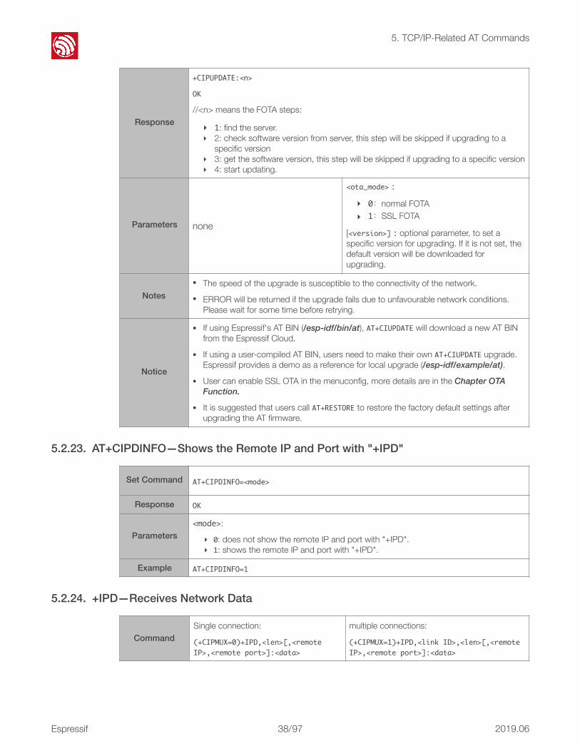
CommandExecute Command:
AT+CIUPDATE
Function: normal FOTA.
Set Command:
AT+CIUPDATE=<ota_mode>[,<version>]
Function: set FOTA mode and upgrade to a specific version.
Espressif ! /!37 97 2019.06
!
5. TCP/IP-Related AT Commands
5.2.23. AT+CIPDINFO—Shows the Remote IP and Port with "+IPD"
5.2.24. +IPD—Receives Network Data
Response
+CIPUPDATE:<n>
OK
//<n> means the FOTA steps:
‣ 1: find the server. ‣ 2: check software version from server, this step will be skipped if upgrading to a
specific version ‣ 3: get the software version, this step will be skipped if upgrading to a specific version ‣ 4: start updating.
Parameters none
<ota_mode>:
‣ 0:normal FOTA ‣ 1:SSL FOTA
[<version>]:optional parameter, to set a specific version for upgrading. If it is not set, the default version will be downloaded for upgrading.
Notes• The speed of the upgrade is susceptible to the connectivity of the network. • ERROR will be returned if the upgrade fails due to unfavourable network conditions.
Please wait for some time before retrying.
Notice
• If using Espressif's AT BIN (/esp-idf/bin/at), AT+CIUPDATE will download a new AT BIN from the Espressif Cloud.
• If using a user-compiled AT BIN, users need to make their own AT+CIUPDATE upgrade. Espressif provides a demo as a reference for local upgrade (/esp-idf/example/at).
• User can enable SSL OTA in the menuconfig, more details are in the Chapter OTA Function.
• It is suggested that users call AT+RESTORE to restore the factory default settings after upgrading the AT firmware.
Set Command AT+CIPDINFO=<mode>
Response OK
Parameters<mode>:
‣ 0: does not show the remote IP and port with "+IPD". ‣ 1: shows the remote IP and port with "+IPD".
Example AT+CIPDINFO=1
CommandSingle connection:
(+CIPMUX=0)+IPD,<len>[,<remoteIP>,<remoteport>]:<data>
multiple connections:
(+CIPMUX=1)+IPD,<linkID>,<len>[,<remoteIP>,<remoteport>]:<data>
Espressif ! /!38 97 2019.06

!
5. TCP/IP-Related AT Commands
5.2.25. AT+PING—Ping Packets
Parameters
The command is valid in normal command mode. When the module receives network data, it will send the data through the serial port using the +IPD command.
• [<remoteIP>]: remote IP, enabled by command AT+CIPDINFO=1.
• [<remoteport>]: remote port, enabled by command AT+CIPDINFO=1.
• <linkID>: ID number of connection.
• <len>: data length.
• <data>: data received.
Set CommandAT+PING=<IP>
Function: Ping packets.
Response
+PING:<time>
OK
or
+PING:TIMEOUT
ERROR
Parameters• <IP>: string; host IP or domain name • <time>: the response time of ping
NotesAT+PING="192.168.1.1"
AT+PING="www.baidu.com"
Espressif ! /!39 97 2019.06

!
6. BLE-Related AT Commands
6. BLE-Related AT Commands 6.1. Overview
Commands Description
AT+BLEINIT Bluetooth Low Energy (BLE) initialization
AT+BLEADDR Sets BLE device's address
AT+BLENAME Sets BLE device's name
AT+BLESCANPARAM Sets parameters of BLE scanning
AT+BLESCAN Enables BLE scanning
AT+BLESCANRSPDATA Sets BLE scan response
AT+BLEADVPARAM Sets parameters of BLE advertising
AT+BLEADVDATA Sets BLE advertising data
AT+BLEADVSTART Starts BLE advertising
AT+BLEADVSTOP Stops BLE advertising
AT+BLECONN Establishes BLE connection
AT+BLECONNPARAM Updates parameters of BLE connection
AT+BLEDISCONN Ends BLE connection
AT+BLEDATALEN Sets BLE data length
AT+BLECFGMTU Sets BLE MTU length
AT+BLEGATTSSRVCRE Generic Attributes Server (GATTS) creates services
AT+BLEGATTSSRVSTART GATTS starts services
AT+BLEGATTSSRVSTOP GATTS stops services
AT+BLEGATTSSRV GATTS discovers services
AT+BLEGATTSCHAR GATTS discovers characteristics
AT+BLEGATTSNTFY GATTS notifies of characteristics
AT+BLEGATTSIND GATTS indicates characteristics
AT+BLEGATTSSETATTR GATTS sets attributes
AT+BLEGATTCPRIMSRV Generic Attributes Client (GATTC) discovers primary services
AT+BLEGATTCINCLSRV GATTC discovers included services
Commands
Espressif ! /!40 97 2019.06

!
6. BLE-Related AT Commands
AT+BLEGATTCCHAR GATTC discovers characteristics
AT+BLEGATTCRD GATTC reads characteristics
AT+BLEGATTCWR GATTC writes characteristics
AT+BLESPPCFG Configures BLE SPP (Serial Port Profile)
AT+BLESPP Enables BLE SPP
AT+BLESECPARAM Sets Parameters of BLE SMP (Security Manager Specification)
AT+BLEENC Starts a Pairing Request
AT+BLEENCRSP Sets a Pairing Response
AT+BLEKEYREPLY Reply to a Pairing Key
AT+BLECONFREPLY Reply to a Pairing Result
AT+BLEENCDEV Lists All Devices that Bonded
AT+BLEENCCLEAR Unbinds Device
DescriptionCommands
⚠ Notice: • Download BLE Spec (ESP32 supports Core Version 4.2): https://www.bluetooth.com/specifications/
adopted-specifications
• The BLE commands and the UART-Wi-Fi passthrough mode cannot be used together, so before BLE initialization, please ensure that the UART-Wi-Fi passthrough mode is not enabled (AT+CIPMODE=0).
Espressif ! /!41 97 2019.06

!
6. BLE-Related AT Commands
6.2. Commands 6.2.1. AT+BLEINIT—BLE Initialization
6.2.2. AT+BLEADDR—Sets BLE Device's Address
Commands
Query Command:
AT+BLEINIT?
Function: to check the initialization status of BLE.
Set Command:
AT+BLEINIT=<init>
Function: to initialize the role of BLE.
Response
If BLE is not initialized, it will return:
+BLEINIT:0
OK
If BLE is initialized, it will return:
+BLEINIT:<role>
OK
OK
Parameter
<init>:
‣ 0: de-init BLE, disable BLE RF * ‣ 1: client role ‣ 2: server role
Notes
• Before using BLE AT commands, this command has to be called first to trigger the initialization process.
• After being initialized, the BLE role cannot be changed directly. If the user wants to change the BLE role, AT+RST or AT+BLEINIT=0 needs to be called first.
• If using ESP32 as a BLE server, a service bin should be downloaded into Flash.
‣ at_customize.bin has to be downloaded, so that the relevant commands can be used. Please refer to the ESP32_Customize_Partitions for more details.
‣ To learn how to generate a service bin, please refer to esp32-at/tools/readme.md.
‣ The download address of the service bin is the "ble_data" address in esp32-at/at_customize.csv.
Example AT+BLEINIT=1
CommandsQuery Command:
AT+BLEADDR?
Function: to get the BLE public address.
Set Command:
AT+BLEADDR=<addr_type>,<random_addr>
Function: to set the BLE random address.
Response+BLEADDR:<BLE_public_addr>
OKOK
Parameter<addr_type>:
‣ 0: public address ‣ 1: random address
Espressif ! /!42 97 2019.06
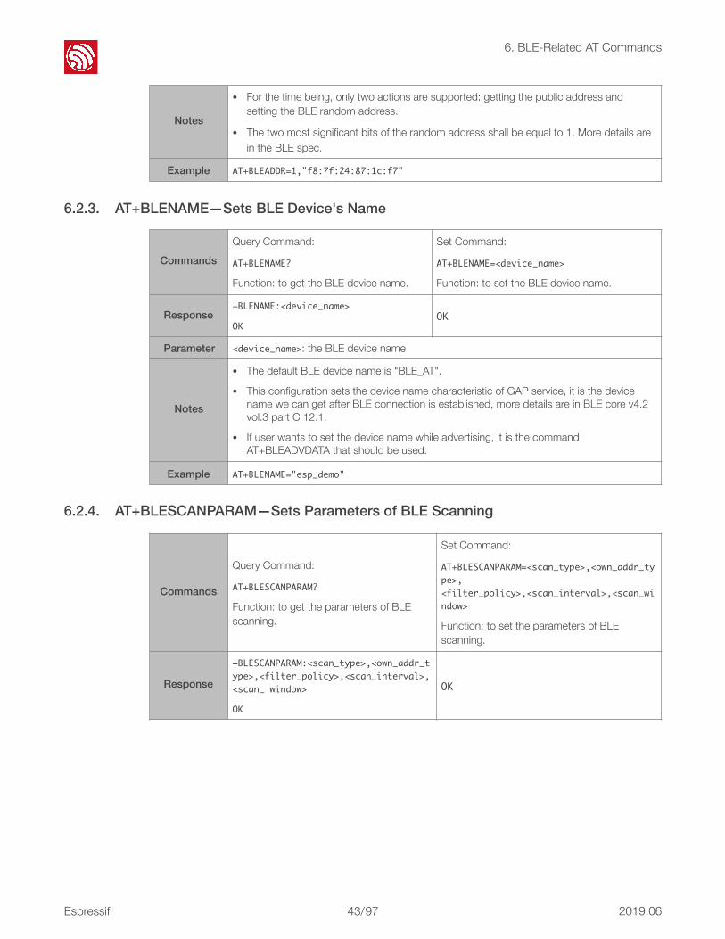
!
6. BLE-Related AT Commands
6.2.3. AT+BLENAME—Sets BLE Device's Name
6.2.4. AT+BLESCANPARAM—Sets Parameters of BLE Scanning
Notes
• For the time being, only two actions are supported: getting the public address and setting the BLE random address.
• The two most significant bits of the random address shall be equal to 1. More details are in the BLE spec.
Example AT+BLEADDR=1,"f8:7f:24:87:1c:f7"
CommandsQuery Command:
AT+BLENAME?
Function: to get the BLE device name.
Set Command:
AT+BLENAME=<device_name>
Function: to set the BLE device name.
Response+BLENAME:<device_name>
OKOK
Parameter <device_name>: the BLE device name
Notes
• The default BLE device name is "BLE_AT".
• This configuration sets the device name characteristic of GAP service, it is the device name we can get after BLE connection is established, more details are in BLE core v4.2 vol.3 part C 12.1.
• If user wants to set the device name while advertising, it is the command AT+BLEADVDATA that should be used.
Example AT+BLENAME="esp_demo"
Commands
Query Command:
AT+BLESCANPARAM?
Function: to get the parameters of BLE scanning.
Set Command:
AT+BLESCANPARAM=<scan_type>,<own_addr_type>,<filter_policy>,<scan_interval>,<scan_window>
Function: to set the parameters of BLE scanning.
Response
+BLESCANPARAM:<scan_type>,<own_addr_type>,<filter_policy>,<scan_interval>,<scan_window>
OK
OK
Espressif ! /!43 97 2019.06

!
6. BLE-Related AT Commands
6.2.5. AT+BLESCAN—Enables BLE Scanning
Parameters
<scan_type>:
‣ 0: passive scan ‣ 1: active scan
<own_addr_type>:
‣ 0: public address ‣ 1: random address ‣ 2: RPA public address ‣ 3: RPA random address
<filter_policy>:
‣ 0: BLE_SCAN_FILTER_ALLOW_ALL ‣ 1: BLE_SCAN_FILTER_ALLOW_ONLY_WLST ‣ 2: BLE_SCAN_FILTER_ALLOW_UND_RPA_DIR ‣ 3: BLE_SCAN_FILTER_ALLOW_WLIST_PRA_DIR
<scan_interval>: scan interval
<scan_window>: scan window
Notes <scan_window> CANNOT be larger than <scan_interval>
ExampleAT+BLEINIT=1// role: client
AT+BLESCANPARAM=0,0,0,100,50
CommandsSet Command:
AT+BLESCAN=<enable>[,<interval>]
Function: to enable/disable scanning.
Response+BLESCAN:<addr>,<rssi>,<adv_data>,<scan_rsp_data>,<addr_type>
OK
Espressif ! /!44 97 2019.06

!
6. BLE-Related AT Commands
6.2.6. AT+BLESCANRSPDATA—Sets BLE Scan Response
Parameters
<enable>:
‣ 0: disable scanning ‣ 1: enable scanning
[<interval>]: optional parameter, unit: second
‣ When disabling the scanning, this parameter should be omitted ‣ When enabling the scanning,
- if the <interval> is 0 or omitted, it means that scanning is continuous - if the <interval> is NOT 0, for example, command AT+BLESCAN=1,3 , it means
that scanning should last for 3 seconds and then stop automatically, so that the scanning results be returned.
<addr>: BLE address
<rssi>: signal strength
<adv_data>: advertising data
<scan_rsp_data>: scan response data
<addr_type>:BLE address type
‣ 0: public address ‣ 1: random address ‣ 2: RPA (Resolvable Private Address) public ‣ 3: RPA (Resolvable Private Address) random
Example
AT+BLEINIT=1// role: client
AT+BLESCAN=1 // start scanning
AT+BLESCAN=0 // stop scanning
CommandsSet Command:
AT+BLESCANRSPDATA=<scan_rsp_data>
Function: to set scan response.
Response OK
Parameter<scan_rsp_data>: scan response data is a HEX string. For example, to set the response data as "0x11 0x22 0x33 0x44 0x55", the command should be AT+BLESCANRSPDATA="1122334455".
Note The maximum length of the scan response is 31 bytes.
ExampleAT+BLEINIT=2// role: server
AT+BLESCANRSPDATA="1122334455"
Espressif ! /!45 97 2019.06

!
6. BLE-Related AT Commands
6.2.7. AT+BLEADVPARAM—Sets Parameters of Advertising
Commands
Query Command:
AT+BLEADVPARAM?
Function: to query the parameters of advertising.
Set Command:
AT+BLEADVPARAM=<adv_int_min>,<adv_int_max>,<adv_type>,<own_addr_type>,<channel_map>[,<adv_filter_policy>,<peer_addr_type>,<peer_addr>]
Function: to set the parameters of advertising.
Response
+BLEADVPARAM:<adv_int_min>,<adv_int_max>,<adv_type>,<own_addr_type>,<channel_map>,<adv_filter_policy>,<peer_addr_type>,<peer_addr>
OK
OK
Parameters
<adv_int_min>:minimum value of advertising interval; range: 0x0020 ~ 0x4000
<adv_int_max>:maximum value of advertising interval; range: 0x0020 ~ 0x4000
<adv_type>:
‣ 0: ADV_TYPE_IND ‣ 1: ADV_TYPE_DIRECT_IND_HIGH‣ 2: ADV_TYPE_SCAN_IND‣ 3: ADV_TYPE_NONCONN_IND
<own_addr_type>: own BLE address type
‣ 0: BLE_ADDR_TYPE_PUBLIC‣ 1: BLE_ADDR_TYPE_RANDOM
<channel_map>: channel of advertising
‣ 1: ADV_CHNL_37‣ 2: ADV_CHNL_38‣ 4: ADV_CHNL_39‣ 7: ADV_CHNL_ALL
[<adv_filter_policy>](optional parameter): filter policy of advertising
‣ 0: ADV_FILTER_ALLOW_SCAN_ANY_CON_ANY‣ 1: ADV_FILTER_ALLOW_SCAN_WLST_CON_ANY‣ 2: ADV_FILTER_ALLOW_SCAN_ANY_CON_WLST‣ 3: ADV_FILTER_ALLOW_SCAN_WLST_CON_WLST
[<peer_addr_type>](optional parameter): remote BLE address type
‣ 0: PUBLIC‣ 1: RANDOM
[<peer_addr>](optional parameter): remote BLE address
Note <adv_filter_policy>,<peer_addr_type>,<peer_addr> these three parameters should be set together, or be omitted together.
ExampleAT+BLEINIT=2// role: server
AT+BLEADVPARAM=50,50,0,0,4,0,0,"12:34:45:78:66:88"
Espressif ! /!46 97 2019.06

!
6. BLE-Related AT Commands
6.2.8. AT+BLEADVDATA—Sets Advertising Data
6.2.9. AT+BLEADVSTART—Starts Advertising
6.2.10. AT+BLEADVSTOP—Stops Advertising
CommandsSet Command:
AT+BLEADVDATA=<adv_data>
Function: to set advertising data.
Response OK
Parameters <adv_data>: advertising data; this is a HEX string. For example, to set the advertising data as "0x11 0x22 0x33 0x44 0x55", the command should be AT+BLEADVDATA="1122334455".
Note The maximum length of the advertising data is 31 bytes.
ExampleAT+BLEINIT=2// role: server
AT+BLEADVDATA="1122334455"
CommandsExecute Command:
AT+BLEADVSTART
Function: to start advertising.
Response OK
Parameter None
Notes
• If advertising parameters are NOT set by command AT+BLEADVPARAM=<adv_parameter>, the default parameters will be used.
• If advertising data is NOT set by command AT+BLEADVDATA=<adv_data>, the all zeros data will be sent.
ExampleAT+BLEINIT=2// role: server
AT+BLEADVSTART
CommandsExecute Command:
AT+BLEADVSTOP
Function: to stop advertising.
Response OK
Parameter None
Notes After having started advertising, if the BLE connection is established successfully, it will stop advertising automatically. In such a case, this command does NOT need to be called.
ExampleAT+BLEINIT=2// role: server
AT+BLEADVSTART
AT+BLEADVSTOP
Espressif ! /!47 97 2019.06

!
6. BLE-Related AT Commands
6.2.11. AT+BLECONN—Establishes BLE connection
6.2.12. AT+BLECONNPARAM—Updates parameters of BLE connection
CommandsQuery Command:
AT+BLECONN?
Function: to query the BLE connection.
Set Command:
AT+BLECONN=<conn_index>,<remote_address>[,<addr_type>]
Function: to establish the BLE connection.
Response
+BLECONN:<conn_index>,<remote_address>
OK
If the connection has not been established, there will NOT be <conn_index>and<remote_address>
OK
If the connection established successfully, it will prompt message
+BLECONN:<conn_index>,<remote_address>
It will prompt the message below, if NOT:
+BLECONN:<conn_index>,fail
Parameters
<conn_index>: index of BLE connection; only 0 is supported for the single connection right now, but multiple BLE connections will be supported in the future.
<remote_address>: remote BLE address
[<addr_type>]: optional parameter, default type is public address
‣ 0: public address ‣ 1: random address ‣ 2: RPA (Resolvable Private Address) public ‣ 3: RPA (Resolvable Private Address) random
ExampleAT+BLEINIT=1// role: client
AT+BLECONN=0,"24:0a:c4:09:34:23"
Commands
Query Command:
AT+BLECONNPARAM?
Function: to query the parameters of BLE connection.
Set Command:
AT+BLECONNPARAM=<conn_index>,<min_interval>,<max_interval>,<latency>,<timeout>
Function: to update the parameters of BLE connection.
Response+BLECONNPARAM:<conn_index>,<min_interval>,<max_interval>,<cur_interval>,<latency>,<timeout>
OK
OK// command received
If the setting failed, it will prompt message below:
+BLECONNPARAM:<conn_index>,-1
Espressif ! /!48 97 2019.06
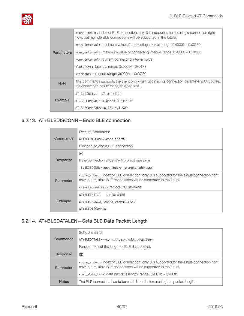
!
6. BLE-Related AT Commands
6.2.13. AT+BLEDISCONN—Ends BLE connection
6.2.14. AT+BLEDATALEN—Sets BLE Data Packet Length
Parameters
<conn_index>: index of BLE connection; only 0 is supported for the single connection right now, but multiple BLE connections will be supported in the future.
<min_interval>: minimum value of connecting interval; range: 0x0006 ~ 0x0C80
<max_interval>: maximum value of connecting interval; range: 0x0006 ~ 0x0C80
<cur_interval>: current connecting interval value
<latency>:latency; range: 0x0000 ~ 0x01F3
<timeout>: timeout; range: 0x000A ~ 0x0C80
Note This commands supports the client only when updating its connection parameters. Of course, the connection has to be established first.
ExampleAT+BLEINIT=1// role: client
AT+BLECONN=0,"24:0a:c4:09:34:23"
AT+BLECONNPARAM=0,12,14,1,500
CommandsExecute Command:
AT+BLEDISCONN=<conn_index>
Function: to end a BLE connection.
ResponseOK
If the connection ends, it will prompt message
+BLEDISCONN:<conn_index>,<remote_address>
Parameter<conn_index>: index of BLE connection; only 0 is supported for the single connection right now, but multiple BLE connections will be supported in the future.
<remote_address>: remote BLE address
ExampleAT+BLEINIT=1// role: client
AT+BLECONN=0,"24:0a:c4:09:34:23"
AT+BLEDISCONN=0
CommandsSet Command:
AT+BLEDATALEN=<conn_index>,<pkt_data_len>
Function: to set the length of BLE data packet.
Response OK
Parameter<conn_index>: index of BLE connection; only 0 is supported for the single connection right now, but multiple BLE connections will be supported in the future.
<pkt_data_len>: data packet's length; range: 0x001b ~ 0x00fb
Notes The BLE connection has to be established before setting the packet length.
Espressif ! /!49 97 2019.06

!
6. BLE-Related AT Commands
6.2.15. AT+BLECFGMTU—Sets GATT MTU Length
6.2.16. AT+BLEGATTSSRVCRE—GATTS Creates Services
ExampleAT+BLEINIT=1// role: client
AT+BLECONN=0,"24:0a:c4:09:34:23"
AT+BLEDATALEN=0,30
Commands
Query Command:
AT+BLECFGMTU?
Function: to query the length of the maximum transmission unit (MTU).
Set Command:
AT+BLECFGMTU=<conn_index>,<mtu_size>
Function: to set the length of the maximum transmission unit (MTU).
Response+BLECFGMTU:<conn_index>,<mtu_size>
OK OK// the command is received
Parameter<conn_index>: index of BLE connection; only 0 is supported for the single connection right now, but multiple BLE connections will be supported in the future.
<mtu_size>: MTU length
Notes
• Only the client can call this command to set the length of MTU. However, the BLE connection has to be established first.
• The actual length of MTU needs to be negotiated. The "OK" response only means that the MTU length must be set. So, the user should use command AT+BLECFGMTU? to query the actual MTU length.
ExampleAT+BLEINIT=1// role: client
AT+BLECONN=0,"24:0a:c4:09:34:23"
AT+BLECFGMTU=0,300
CommandsExecute Command:
AT+BLEGATTSSRVCRE
Function: The Generic Attributes Server (GATTS) creates BLE services.
Response OK
Parameter None
Notes
• If using ESP32 as a BLE server, a service bin should be downloaded into Flash in order to provide services.
‣ To learn how to generate a service bin, please refer to esp32-at/tools/readme.md.
‣ The download address of the service bin is the "ble_data" address in esp32-at/at_customize.csv.
• This command should be called immediately to create services, right after the BLE server is initialized. If a BLE connection is established first, the service creation will fail.
ExampleAT+BLEINIT=2// role: server
AT+BLEGATTSSRVCRE
Espressif ! /!50 97 2019.06

!
6. BLE-Related AT Commands
6.2.17. AT+BLEGATTSSRVSTART—GATTS Starts Services
6.2.18. AT+BLEGATTSSRVSTOP—GATTS Stops Services
6.2.19. AT+BLEGATTSSRV—GATTS Discovers Services
CommandsExecute Command:
AT+BLEGATTSSTART
Function: GATTS starts all services.
Set Command:
AT+BLEGATTSSRVSTART=<srv_index>
Function: GATTS starts a specific service.
Response OK
Parameter None <srv_index>: service's index starting from 1
ExampleAT+BLEINIT=2// role: server
AT+BLEGATTSSRVCRE
AT+BLEGATTSSRVSTART
CommandsExecute Command:
AT+BLEGATTSSTOP
Function: GATTS stops all services.
Set Command:
AT+BLEGATTSSRVSTOP=<srv_index>
Function: GATTS stops a specific service.
Response OK
Parameter None <srv_index>: service's index starting from 1
Example
AT+BLEINIT=2// role: server
AT+BLEGATTSSRVCRE
AT+BLEGATTSSRVSTART
AT+BLEGATTSSRVSTOP
CommandsQuery Command:
AT+BLEGATTSSRV?
Function: GATTS services discovery.
Response+BLEGATTSSRV:<srv_index>,<start>,<srv_uuid>,<srv_type>
OK
Parameters
<srv_index>:service's index starting from 1
<start>:
‣ 0: the service has not started‣ 1: the service has already started
<srv_uuid>:service's UUID
<srv_type>:service's type
‣ 0: is not a primary service‣ 1: is a primary service
Espressif ! /!51 97 2019.06
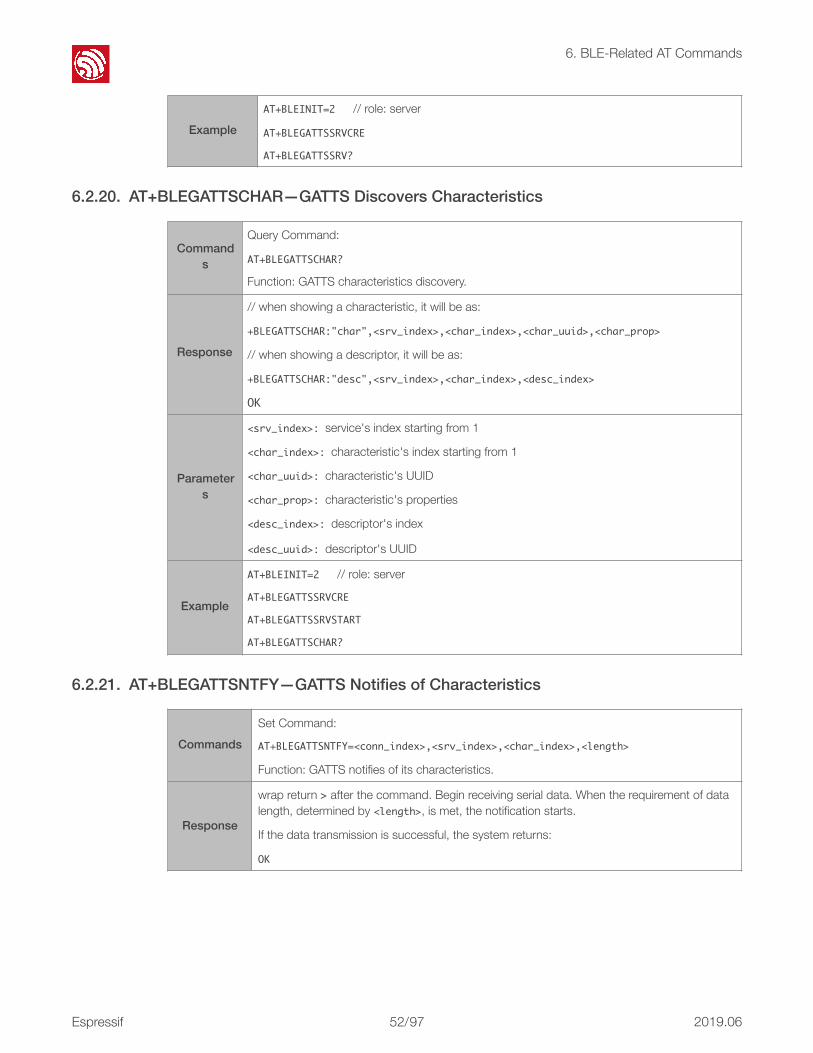
!
6. BLE-Related AT Commands
6.2.20. AT+BLEGATTSCHAR—GATTS Discovers Characteristics
6.2.21. AT+BLEGATTSNTFY—GATTS Notifies of Characteristics
ExampleAT+BLEINIT=2// role: server
AT+BLEGATTSSRVCRE
AT+BLEGATTSSRV?
Commands
Query Command:
AT+BLEGATTSCHAR?
Function: GATTS characteristics discovery.
Response
// when showing a characteristic, it will be as:
+BLEGATTSCHAR:"char",<srv_index>,<char_index>,<char_uuid>,<char_prop>
// when showing a descriptor, it will be as:
+BLEGATTSCHAR:"desc",<srv_index>,<char_index>,<desc_index>
OK
Parameters
<srv_index>:service's index starting from 1
<char_index>:characteristic's index starting from 1
<char_uuid>:characteristic's UUID
<char_prop>:characteristic's properties
<desc_index>:descriptor's index
<desc_uuid>:descriptor's UUID
Example
AT+BLEINIT=2// role: server
AT+BLEGATTSSRVCRE
AT+BLEGATTSSRVSTART
AT+BLEGATTSCHAR?
CommandsSet Command:
AT+BLEGATTSNTFY=<conn_index>,<srv_index>,<char_index>,<length>
Function: GATTS notifies of its characteristics.
Response
wrap return > after the command. Begin receiving serial data. When the requirement of data length, determined by <length>, is met, the notification starts.
If the data transmission is successful, the system returns:
OK
Espressif ! /!52 97 2019.06

!
6. BLE-Related AT Commands
6.2.22. AT+BLEGATTSIND—GATTS Indicates Characteristics
Parameters
<conn_index>: index of BLE connection; only 0 is supported for the single connection right now, but multiple BLE connections will be supported in the future.
<srv_index>:service's index; it can be fetched with command AT+BLEGATTSCHAR?
<char_index>:characteristic's index; it can be fetched with command AT+BLEGATTSCHAR?
<length>: data length
Example
A simple workflow is shown below. Users can refer to Section 9.5 BLE AT Examples for more details.
AT+BLEINIT=2// role: server
AT+BLEGATTSSRVCRE
AT+BLEGATTSSRVSTART
AT+BLEADVSTART// starts advertising. After the client is connected, it must be configured to receive notifications.
AT+BLEGATTSCHAR?// check which characteristic the client will be notified of
// for example, to notify of 4 bytes of data using the 6th characteristic in the 3rd service, use the following command:
AT+BLEGATTSNTFY=0,3,6,4
// after > shows, inputs 4 bytes of data, such as "1234"; then, the data will be transmitted automatically
CommandsSet Command:
AT+BLEGATTSIND=<conn_index>,<srv_index>,<char_index>,<length>
Function: GATTS indicates its characteristics.
Response
wrap return > after the command. Begin receiving serial data. When the requirement of data length, determined by <length>, is met, the indication starts.
If the data transmission is successful, the system returns:
OK
Parameters
<conn_index>:index of BLE connection; only 0 is supported for the single connection right now, but multiple BLE connections will be supported in the future.
<srv_index>:service's index; it can be fetched with command AT+BLEGATTSCHAR?
<char_index>:characteristic's index; it can be fetched with command AT+BLEGATTSCHAR?
<length>: data length
Espressif ! /!53 97 2019.06

!
6. BLE-Related AT Commands
6.2.23. AT+BLEGATTSSETATTR—GATTS Sets Characteristic
Example
A simple workflow is shown below. Users can refer to Section 9.5 BLE AT Examples for more details.
AT+BLEINIT=2// role: server
AT+BLEGATTSSRVCRE
AT+BLEGATTSSRVSTART
AT+BLEADVSTART// starts advertising. After the client is connected, it must be configured to receive indications.
AT+BLEGATTSCHAR?// check for which characteristic the client can receive indications
// for example, to indicate 4 bytes of data using the 7th characteristic in the 3rd service, use the following command:
AT+BLEGATTSIND=0,3,7,4
// after > shows, inputs 4 bytes of data, such as "1234"; then, the data will be transmitted automatically
CommandsSet Command:
AT+BLEGATTSSETATTR=<srv_index>,<char_index>[,<desc_index>],<length>
Function: GATTS sets its characteristic (descriptor).
Response
wrap return > after the command. Begin receiving serial data. When the requirement of data length, determined by <length>, is met, the setting starts.
If the setting is successful, the system returns:
OK
Parameters
<srv_index>:service's index; it can be fetched with command AT+BLEGATTSCHAR?
<char_index>:characteristic's index; it can be fetched with command AT+BLEGATTSCHAR?
[<desc_index>](Optional parameter): descriptor's index. If it is set, this command is used to set the value of the descriptor; if it is not, this command is used to set the value of the characteristic.
<length>:data length
Note If the <length> is larger than the maximum length allowed, the setting will fail.
Example
A simple workflow is shown below. Users can refer to Section 9.5 BLE AT Examples for more details.
AT+BLEINIT=2// role: server
AT+BLEGATTSSRVCRE
AT+BLEGATTSSRVSTART
AT+BLEGATTSCHAR?
// for example, to set 4 bytes of data of the 1st characteristic in the 1st service, use the following command:
AT+BLEGATTSSETATTR=1,1,,4
// after > shows, inputs 4 bytes of data, such as "1234"; then, the setting starts
Espressif ! /!54 97 2019.06
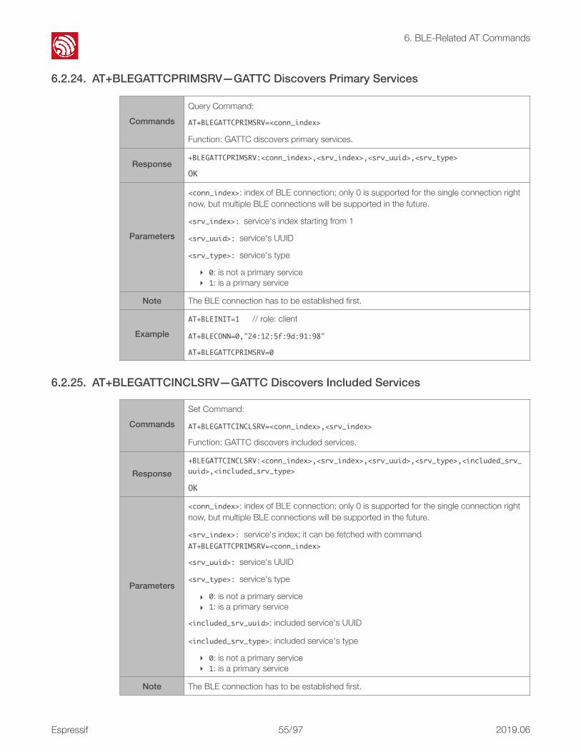
!
6. BLE-Related AT Commands
6.2.24. AT+BLEGATTCPRIMSRV—GATTC Discovers Primary Services
6.2.25. AT+BLEGATTCINCLSRV—GATTC Discovers Included Services
CommandsQuery Command:
AT+BLEGATTCPRIMSRV=<conn_index>
Function: GATTC discovers primary services.
Response+BLEGATTCPRIMSRV:<conn_index>,<srv_index>,<srv_uuid>,<srv_type>
OK
Parameters
<conn_index>: index of BLE connection; only 0 is supported for the single connection right now, but multiple BLE connections will be supported in the future.
<srv_index>:service's index starting from 1
<srv_uuid>:service's UUID
<srv_type>:service's type
‣ 0: is not a primary service‣ 1: is a primary service
Note The BLE connection has to be established first.
ExampleAT+BLEINIT=1// role: client
AT+BLECONN=0,"24:12:5f:9d:91:98"
AT+BLEGATTCPRIMSRV=0
CommandsSet Command:
AT+BLEGATTCINCLSRV=<conn_index>,<srv_index>
Function: GATTC discovers included services.
Response+BLEGATTCINCLSRV:<conn_index>,<srv_index>,<srv_uuid>,<srv_type>,<included_srv_uuid>,<included_srv_type>
OK
Parameters
<conn_index>: index of BLE connection; only 0 is supported for the single connection right now, but multiple BLE connections will be supported in the future.
<srv_index>:service's index; it can be fetched with command AT+BLEGATTCPRIMSRV=<conn_index>
<srv_uuid>:service's UUID
<srv_type>:service's type
‣ 0: is not a primary service‣ 1: is a primary service
<included_srv_uuid>: included service's UUID
<included_srv_type>: included service's type
‣ 0: is not a primary service‣ 1: is a primary service
Note The BLE connection has to be established first.
Espressif ! /!55 97 2019.06

!
6. BLE-Related AT Commands
6.2.26. AT+BLEGATTCCHAR—GATTC Discovers Characteristics
6.2.27. AT+BLEGATTCRD—GATTC Reads a Characteristic
Example
AT+BLEINIT=1// role: client
AT+BLECONN=0,"24:12:5f:9d:91:98"
AT+BLEGATTCPRIMSRV=0
AT+BLEGATTCINCLSRV=0,1// set a specific index according to the result of the previous command
CommandsSet Command:
AT+BLEGATTCCHAR=<conn_index>,<srv_index>
Function: GATTC discovers characteristics.
Response
// when showing a characteristic, it will be as:
+BLEGATTCCHAR:"char",<conn_index>,<srv_index>,<char_index>,<char_uuid>,<char_prop>
// when showing a descriptor, it will be as:
+BLEGATTCCHAR:"desc",<conn_index>,<srv_index>,<char_index>,<desc_index>,<desc_uuid>
OK
Parameters
<conn_index>: index of BLE connection; only 0 is supported for the single connection right now, but multiple BLE connections will be supported in the future.
<srv_index>:service's index; it can be fetched with command AT+BLEGATTCPRIMSRV=<conn_index>
<char_index>:characteristic's index starting from 1
<char_uuid>:characteristic's UUID
<char_prop>:characteristic's properties
<desc_index>:descriptor's index
<desc_uuid>:descriptor's UUID
Note The BLE connection has to be established first.
Example
AT+BLEINIT=1// role: client
AT+BLECONN=0,"24:12:5f:9d:91:98"
AT+BLEGATTCPRIMSRV=0
AT+BLEGATTCCHAR=0,1// set a specific index, according to the result of the previous command
CommandsSet Command:
AT+BLEGATTCRD=<conn_index>,<srv_index>,<char_index>[,<desc_index>]
Function: GATTC to read a characteristic or descriptor.
Espressif ! /!56 97 2019.06

!
6. BLE-Related AT Commands
6.2.28. AT+BLEGATTCWR—GATTC Writes Characteristic
Response+BLEGATTCRD:<conn_index>,<len>,<value>
OK
Parameters
<conn_index>: index of BLE connection; only 0 is supported for the single connection right now, but multiple BLE connections will be supported in the future.
<srv_index>:service's index; it can be fetched with command AT+BLEGATTCPRIMSRV=<conn_index>
<char_index>:characteristic's index; it can be fetched with command AT+BLEGATTCCHAR=<conn_index>,<srv_index>
[<desc_index>](Optional parameter): descriptor's index. If it is set, the value of the target descriptor will be read; if it is not set, the value of the target characteristic will be read.
<len>:data length
<value>:HEX string
‣ Characteristic's value, read by command AT+BLEGATTCRD=<conn_index>,<srv_index>,<char_index>. For example, if the response is "+BLEGATTCRD:0,1,30", it means that the value length is 1, and the content is "0x30".
‣ Descriptor's value, read by command AT+BLEGATTCRD=<conn_index>,<srv_index>,<char_index>,<desc_index>. For example, if the response is "+BLEGATTCRD:0,4,30313233", it means that the value length is 4, and the content is "0x30 0x31 0x32 0x33".
Note• The BLE connection has to be established first.
• If the target characteristic cannot be read, it will return "ERROR".
Example
AT+BLEINIT=1// role: client
AT+BLECONN=0,"24:12:5f:9d:91:98"
AT+BLEGATTCPRIMSRV=0
AT+BLEGATTCCHAR=0,3// set a specific index, according to the result of the previous command
// for example, to read 1st descriptor of the 2nd characteristic in the 3rd service, use the following command:
AT+BLEGATTCRD=0,3,2,1
CommandsSet Command:
AT+BLEGATTCWR=<conn_index>,<srv_index>,<char_index>[,<desc_index>],<length>
Function: GATTC writes characteristics or descriptor.
Response
wrap return > after the command. Begin receiving serial data. When the requirement of data length, determined by <length>, is met, the writting starts.
If the setting is successful, the system returns:
OK
Espressif ! /!57 97 2019.06

!
6. BLE-Related AT Commands
6.2.29. AT+BLESPPCFG—Configures BLE SPP
Parameters
<conn_index>: index of BLE connection; only 0 is supported for the single connection right now, but multiple BLE connections will be supported in the future.
<srv_index>:service's index; it can be fetched with command AT+BLEGATTCPRIMSRV=<conn_index>
<char_index>:characteristic's index; it can be fetched with command AT+BLEGATTCCHAR=<conn_index>,<srv_index>
[<desc_index>] (optional parameter): descriptor's index. If it is set, the value of the target descriptor will be written; if it is not set, the value of the target characteristic will be written.
<length>:data length
Note• The BLE connection has to be established first.
• If the target characteristic cannot be written, it will return "ERROR".
Example
AT+BLEINIT=1// role: client
AT+BLECONN=0,"24:12:5f:9d:91:98"
AT+BLEGATTCPRIMSRV=0
AT+BLEGATTCCHAR=0,3// set a specific index, according to the result of the previous command
// for example, to write 6 bytes of data to the 4th characteristic in the 3rd service, use the following command:
AT+BLEGATTCWR=0,3,4,,6
// after > shows, inputs 6 bytes of data, such as "123456"; then, the writing starts
Set Command
AT+BLESPPCFG=<cfg_enable>,<tx_srv_index>,<tx_char_index>,<rx_srv_index>,<rx_srv_index>
Function: to configure BLE SPP (Serial Port Profile, UART-BLE passthrough mode). It will take two characteristics: one for sending data, the other for receiving data.
Response OK
Espressif ! /!58 97 2019.06

!
6. BLE-Related AT Commands
Parameters
<cfg_enable>:
• 0: clears BLE SPP configuration, the following four parameters need not to be set.
• 1: sets BLE SPP configuration, the following four parameters have to be set.
<tx_srv_index>: the index of the service that contains the target characteristic for sending data.
• If ESP runs as a BLE server, <tx_srv_index> will be a local service ID which can be obtained by using the command AT+BLEGATTSSRVCRE.
• If ESP runs as a BLE client, <tx_srv_index> will be a remote service ID which can be obtained by using the command AT+BLEGATTCPRIMSRV=<conn_index>.
<tx_char_index>: the index of the characteristic that is used for sending data.
• If ESP runs as a BLE server, <tx_char_index> will be a local characteristic ID which can be obtained by using the command AT+BLEGATTSCHAR. The characteristic should support notification or indication.
• If ESP runs as a BLE client, <tx_char_index> will be a remote characteristic ID which can be obtained by using the command AT+BLEGATTCCHAR=<conn_index>,<srv_index>. The characteristic should support writing access.
<rx_srv_index>: the index of the service that contains the target characteristic for receiving data.
• If ESP runs as a BLE server, <rx_srv_index> will be a local service ID which can be obtained by using the command AT+BLEGATTSSRVCRE.
• If ESP runs as a BLE client, <rx_srv_index> will be a remote service ID which can be obtained by using the command AT+BLEGATTCPRIMSRV=<conn_index>.
<rx_char_index>: the index of the characteristic that is used for receiving data.
• If ESP runs as a BLE server, <rx_char_index> will be a local characteristic ID which can be obtained by using the command AT+BLEGATTSCHAR. The characteristic should support writing access.
• If ESP runs as a BLE client, <rx_char_index> will be a remote characteristic ID which can be obtained by using the command AT+BLEGATTCCHAR=<conn_index>,<srv_index>. The characteristic should support notification or indication.
Note
• This command can be called after initializing BLE. • This command can be called multiple times, the final configuration depends on the last
setting. • If the target characteristic cannot be written, it will return "ERROR". This configuration will
not be saved in flash, and will be cleared after system reboot or BLE shutdown.
Espressif ! /!59 97 2019.06

!
6. BLE-Related AT Commands
6.2.30. AT+BLESPP—Enables BLE SPP
Example
AT+BLEINIT=2// role: server
AT+BLEGATTSSRVCRE
AT+BLEGATTSSRVSTART
AT+BLEGATTSCHAR?
AT+BLEADVSTART// start advertising
// After a BLE client connects to the ESP server, the message +BLECONN:0,<clientMAC> will appear.
// For example, to configure the 7th characteristic in the 1st service as a TX channel for sending data; and configure the 5th characteristic in the 1st service as a RX channel for receiving data, use the following command:
AT+BLESPPCFG=1,1,7,1,5
// The client needs to listen to the notification/indication from TX channel which is the 7th characteristic in this example.
Execute Command
AT+BLESPP
Function: to enable BLE SPP (Serial Port Profile, UART-BLE passthrough mode).
Response
OK
> // waiting for serial data
The wrap return is > after this command is executed. Then, ESP32 enters UART-BLE passthrough mode.
When a single packet containing +++ is received, ESP32 returns to normal command mode. Please wait for at least one second before sending the next AT command.
Note
• When calling this command to enable BLE SPP, the configuration set by AT+BLESPPCFG will be checked. If the configuration has not been set, cleared, or is invalid (for example, the characteristic fails to meet requirements), the command will return "ERROR".
• If the UART-WiFi passthrough mode has been enabled, the command will return "ERROR".
• If the BLE connection is not established, or the multiple connections mode is enabled, the command will return "ERROR".
• If the BLE is advertising, the command will return "ERROR". However, the command will be enabled successfully if the advertising type is ADV_TYPE_NONCONN_IND.
• If the BLE connection breaks unexpectedly in UART-BLE passthrough mode, the ESP will keep trying to restore the connection.
Espressif ! /!60 97 2019.06

!
6. BLE-Related AT Commands
6.2.31. AT+BLESECPARAM—Set Parameters of BLE SMP
Example
AT+BLEINIT=2// role: server
AT+BLEGATTSSRVCRE
AT+BLEGATTSSRVSTART
AT+BLEGATTSCHAR?
AT+BLEADVSTART// start advertising
// After a BLE client connects to the ESP server, the message +BLECONN:0,<clientMAC> will return.
// For example, to configure the 7th characteristic in the 1st service as a TX channel for sending data; and configure the 5th characteristic in the 1st service as a RX channel for receiving data, use the following command:
AT+BLESPPCFG=1,1,7,1,5
// The client needs to listen to the notification/indication from TX channel which is the 7th characteristic in this example.
AT+BLESPP // enable BLE SPP
Commands
Query Command:
AT+BLESECPARAM?
Function: to query parameters of BLE SMP (Security Manager Specification).
Set Command:
AT+BLESECPARAM=<auth_req>,<iocap>,<key_size>,<init_key>,<rsp_key>
Function: to set parameters of BLE SMP.
Response+BLESECPARAM:<auth_req>,<iocap>,<key_size>,<init_key>,<rsp_key>
OK
OK
Espressif ! /!61 97 2019.06

!
6. BLE-Related AT Commands
6.2.32. AT+BLEENC—Starts a Pairing Request
Parameters
<auth_req>:authentication requirements
‣ 0:ESP_LE_AUTH_NO_BOND‣ 1:ESP_LE_AUTH_BOND‣ 2:ESP_LE_AUTH_REQ_MITM‣ 4:ESP_LE_AUTH_REQ_SC_ONLY‣ 5:ESP_LE_AUTH_REQ_SC_BOND‣ 6:ESP_LE_AUTH_REQ_SC_MITM‣ 7:ESP_LE_AUTH_REQ_SC_MITM_BOND
<iocap>:IO capabilities
‣ 0:ESP_IO_CAP_OUT /*!<DisplayOnly*/ ‣ 1:ESP_IO_CAP_IO /*!<DisplayYesNo*/ ‣ 2:ESP_IO_CAP_IN /*!<KeyboardOnly*/ ‣ 3:ESP_IO_CAP_NONE /*!<NoInputNoOutput*/ ‣ 4:ESP_IO_CAP_KBDISP /*!<Keyboarddisplay*/
<key_size>:encryption key size, range : [7, 16]
<init_key>:
‣ if bit0 is 1, it meansESP_BLE_ENC_KEY_MASK //exchangetheencryptionkey‣ if bit1 is 1, it means ESP_BLE_ID_KEY_MASK //exchangetheIRKkey‣ if bit2 is 1, it means ESP_BLE_CSR_KEY_MASK //exchangetheCSRKkey‣ if bit3 is 1, it means ESP_BLE_LINK_KEY_MASK //exchangethelinkkey(thiskey
isusedonlyintheBLE&BR/EDR-coexistmode)
<rsp_key>:response key
‣ if bit0 is 1, it meansESP_BLE_ENC_KEY_MASK //exchangetheencryptionkey‣ if bit1 is 1, it means ESP_BLE_ID_KEY_MASK //exchangetheIRKkey‣ if bit2 is 1, it means ESP_BLE_CSR_KEY_MASK //exchangetheCSRKkey‣ if bit3 is 1, it meansESP_BLE_LINK_KEY_MASK //exchangethelinkkey(thiskey
isusedonlyintheBLE&BR/EDR-coexistmode)
Note This configuration should be set before the BLE connection is established.
Example AT+BLESECPARAM=1,4,16,3,3
CommandsSet Command:
AT+BLEENC=<conn_index>,<sec_act>
Function: to start a pairing request.
Response OK
Parameters
<conn_index>: index of BLE connection; only 0 is supported for the single connection right now, but multiple BLE connections will be supported in the future.
<sec_act>:
‣ 0:ESP_BLE_SEC_NONE ‣ 1:ESP_BLE_SEC_ENCRYPT ‣ 2:ESP_BLE_SEC_ENCRYPT_NO_MITM ‣ 3:ESP_BLE_SEC_ENCRYPT_MITM
ExampleAT+BLESECPARAM=1,4,16,3,3
AT+BLEENC=0,3
Espressif ! /!62 97 2019.06

!
6. BLE-Related AT Commands
6.2.33. AT+BLEENCRSP—Sets a Pairing Response
6.2.34. AT+BLEKEYREPLY—Reply to a Pairing Key
6.2.35. AT+BLECONFREPLY—Reply to a Pairing Result
CommandsSet Command:
AT+BLEENCRSP=<conn_index>,<accept>
Function: to set a pairing response.
Response OK
Parameters
<conn_index>: index of BLE connection; only 0 is supported for the single connection right now, but multiple BLE connections will be supported in the future.
<accept>:
‣ 0:reject ‣ 1:accept
Example AT+BLEENCRSP=0,1
CommandsSet Command:
AT+BLEKEYREPLY=<conn_index>,<key>
Function: to reply to a pairing key.
Response OK
Parameters<conn_index>: index of BLE connection; only 0 is supported for the single connection right now, but multiple BLE connections will be supported in the future.
<key>: pairing key
Example AT+BLEKEYREPLY=0,649784
CommandsSet Command:
AT+BLECONFREPLY=<conn_index>,<confirm>
Function: to reply to a pairing result when the pairing key cannot be used.
Response OK
Parameters
<conn_index>: index of BLE connection; only 0 is supported for the single connection right now, but multiple BLE connections will be supported in the future.
<confirm>:
‣ 0:No ‣ 1:Yes
Example// confirm that pairing succeeded
AT+BLECONFREPLY=0,1
Espressif ! /!63 97 2019.06

!
6. BLE-Related AT Commands
6.2.36. AT+BLEENCDEV—Lists All Devices that Bonded
6.2.37. AT+BLEENCCLEAR—Unbind Device
CommandQuery Command:
AT+BLEENCDEV?
Response+BLEENCDEV:<enc_dev_index>,<mac_address>
OK
Parameters<enc_dev_index>: index of bonded devices; only 0 is supported for the single connection right now, but multiple BLE connections will be supported in the future.
<mac_address>: Mac address
Example AT+BLEENCDEV?
Commands
Set Command:
AT+BLEENCCLEAR=<enc_dev_index>
Function: unbind a device with a specific index.
Execute Command:
AT+BLEENCCLEAR
Function: unbind all devices.
Response OK
Parameters
<enc_dev_index>: index of bonded devices; only 0 is supported for the single connection right now, but multiple BLE connections will be supported in the future.
Example AT+BLEENCCLEAR
Espressif ! /!64 97 2019.06

!
7. AT Commands with Configuration Saved in the NVS Area
7. AT Commands with Configuration Saved in the
NVS Area Commands Examples
AT+UART AT+UART=115200,8,1,0,3
AT+UART_DEF AT+UART_DEF=115200,8,1,0,3
AT+CWDHCP AT+CWDHCP=1,1
AT+CIPSTAMAC AT+CIPSTAMAC="18:fe:35:98:d3:7b"
AT+CIPAPMAC AT+CIPAPMAC="1a:fe:36:97:d5:7b"
AT+CIPSTA AT+CIPSTA="192.168.6.100"
AT+CIPAP AT+CIPAP="192.168.5.1"
AT+CWDHCPS AT+CWDHCPS=1,3,"192.168.4.10","192.168.4.15"
AT+SAVETRANSLINK AT+SAVETRANSLINK=1,"192.168.6.10",1001
AT+CWMODE AT+CWMODE=3
AT+CWJAP AT+CWJAP="abc","0123456789"
AT+CWSAP AT+CWSAP="ESP32","12345678",5,3
AT+CWAUTOCONN AT+CWAUTOCONN=1
AT+CIPSSLCCONF AT+CIPSSLCCONF=1,3,0,0
⚠ Notice:
NVS parameter area is 0xFA000 ~ 0x110000, and it is 88 KB in size.
Espressif ! /!65 97 2019.06

!
8. AT Messages
8. AT Messages Messages of ESP32 AT are as below:
Messages Description
ready The AT firmware is ready.
ERROR AT command error, or error occurred during execution.
WIFICONNECTED ESP station connected to an AP.
WIFIGOTIP ESP station got IP address.
WIFIDISCONNECT ESP station disconnected from an AP.
busyp...Busy processing. The system is in process of handling the previous command, cannot accept the newly input.
<conn_id>,CONNECT A network connection of which ID is <conn_id> is established.
<conn_id>,CLOSED A network connection of which ID is <conn_id> ends.
+IPD Network data received.
+STA_CONNECTED:<sta_mac> A station connects to the ESP softAP.
+DIST_STA_IP:<sta_mac>,<sta_ip>
ESP softAP distributes an IP address to the station connected.
+STA_DISCONNECTED:<sta_mac>
A station disconnects from the ESP softAP.
+BLECONN A BLE connection established.
+BLEDISCONN A BLE connection ends.
+READ A read operation from BLE connection
+WRITE A write operation from BLE connection
+NOTIFY A notification from BLE connection
+INDICATE An indication from BLE connection
+BLESECNTFYKEY BLE SMP key
+BLEAUTHCMPL BLE SMP pairing completed.
Espressif ! /!66 97 2019.06

!
9. AT Commands Examples
9. AT Commands Examples Herein we introduce some examples of how to use Espressif's AT Commands.
9.1. ESP32 as a TCP Client in Single Connection 1. Set the Wi-Fi mode:
AT+CWMODE=3//SoftAP+Stationmode
Response:
OK
2. Connect to the router:
AT+CWJAP="SSID","password"//SSIDandpasswordofrouter
Response:
OK
3. Query the device's IP:
AT+CIFSR
Response:
192.168.3.106//devicegotanIPfromrouter
4. Connect the PC to the same router which ESP32 is connected to. Use a network tool on the PC to create a TCP server.
- For example, the TCP server on PC is 192.168.3.116, port 8080.
5. ESP32 is connected to the TCP server as a client:
AT+CIPSTART="TCP","192.168.3.116",8080//protocol、serverIP&port
6. Send data:
AT+CIPSEND=4//setdatelengthwhichwillbesent,suchas4bytes
>TEST//enterthedata,noCR
Response:
SENDOK
⚠ Notice:
• If the number of bytes inputted are more than the size defined (n):
- the system will reply busy, and send the first n bytes.
- and after sending the first n bytes, the system will reply SENDOK.
Espressif ! /!67 97 2019.06

!
9. AT Commands Examples
7. Receive data:
+IPD,n:xxxxxxxxxx//receivednbytes,data=xxxxxxxxxxx
9.2. UDP Transmission UDP transmission is established via AT+CIPSTART. There is no such distinction between UDP server and UDP client.
1. Set the Wi-Fi mode:
AT+CWMODE=3//SoftAP+Stationmode
Response:
OK
2. Connect to the router:
AT+CWJAP="SSID","password"//SSIDandpasswordofrouter
Response:
OK
3. Query the device's IP:
AT+CIFSR
Response:
+CIFSR:STAIP,"192.168.101.104"//IPaddressofESP32Station
4. Connect the PC to the same router which ESP32 is connected to. Use a network tool on the PC to create UDP transmission.
- For example, the PC's IP address is 192.168.101.116 and the port is 8080.
5. Below are two examples of UDP transmission:
9.2.1. UDP (with Fixed Remote IP and Port)
In UDP transmission, whether the remote IP and port are fixed or not is determined by the last parameter of AT+CIPSTART, namely 0. 0 means that the remote IP and port are fixed and cannot be changed. A specific ID is given to such a connection, ensuring that the data sender and receiver will not be replaced by other devices.
1. Enable multiple connections:
AT+CIPMUX=1
Response:
OK
2. Create a UDP transmission, with the ID being 4, for example.
AT+CIPSTART=4,"UDP","192.168.101.110",8080,1112,0
Espressif ! /!68 97 2019.06

!
9. AT Commands Examples
Response:
4,CONNECT
OK
3. Send data:
AT+CIPSEND=4,7//send7bytestotransmissionNO.4
>UDPtest//enterthedata,noCR
Response:
SENDOK
4. Receive data:
+IPD,4,n:xxxxxxxxxx//receivednbytes,data=xxxxxxxxxxx
5. Close UDP transmission No.4:
AT+CIPCLOSE=4
Response:
4,CLOSED
OK
9.2.2. UDP (with Changeable Remote IP and Port)
1. Create a UDP transmission with the last parameter being 2.
AT+CIPSTART="UDP","192.168.101.110",8080,1112,2
Response:
CONNECT
OK
📖 Notes:
• "192.168.101.110" and 8080 are the remote IP and port of UDP transmission on the remote side, i.e., the UDP configuration set by PC.
• 1112 is the local port number of ESP32. Users can define this port number. The value of this parameter will be random if it is not defined beforehand.
• 0 means that the remote IP and port are fixed and cannot be changed. For example, if another PC also creates a UDP entity and sends data to ESP32 port 1112, ESP32 can receive the data sent from UDP port 1112. But when data are sent using AT command AT+CIPSEND=4,X, it will still be sent to the first PC end. If parameter 0is not used, the data will be sent to the new PC.
⚠ Notice:
• If the number of bytes inputted are more than the size defined (n):
- the system will reply busy, and send the first n bytes.
- and after sending the first n bytes, the system will reply SENDOK.
Espressif ! /!69 97 2019.06

!
9. AT Commands Examples
2. Send data:
AT+CIPSEND=7//send7bytes
>UDPtest//enterthedata,noCR
Response:
SENDOK
3. If you want to send data to any other UDP terminals, please designate the IP and port of the target terminal in the command.
AT+CIPSEND=6,"192.168.101.111",1000//sendsixbytes
>abcdef//enterthedata,noCR
Response:
SENDOK
4. Receive data:
+IPD,n:xxxxxxxxxx//receivednbytes,data=xxxxxxxxxxx
5. Close UDP transmission:
AT+CIPCLOSE
Response:
CLOSED
OK
9.3. Transparent Transmission AT Demo supports transparent transmission only when ESP32 works as a TCP client in single connection or UDP transmission.
📖 Notes:
• "192.168.101.110" and 8080 here refer to the IP and port of the remote UDP transmission terminal which is created on a PC in Section 9.2.1.
• 1112 is the local port of ESP32. Users can define this port. The value of this parameter will be random if it is not defined beforehand.
• 2 means the means the opposite terminal of UDP transmission can be changed. The remote IP and port will be automatically changed to those of the last UDP connection to ESP32.
⚠ Notice:
• If the number of bytes inputted are more than the size defined (n):
- the system will reply busy, and send the first n bytes.
- and after sending the first n bytes, the system will reply SENDOK.
Espressif ! /!70 97 2019.06

!
9. AT Commands Examples
9.3.1. ESP32 as a TCP Client in UART-Wi-Fi Passthrough (Single Connection Mode)
Here is an example of the ESP32 Station working as a TCP client in single connection mode of transparent transmission.
1. Set the Wi-Fi mode:
AT+CWMODE=3//SoftAP+Stationmode
Response:
OK
2. Connect to the router:
AT+CWJAP="SSID","password"//SSIDandpasswordofrouter
Response:
OK
3. Query the device's IP:
AT+CIFSR
Response:
192.168.101.105//device'sIPthatgotfromrouter
4. Connect the PC to the same router to which ESP32 is connected. Use a network tool on the PC to create a TCP server.
- For example, the PC's IP address is 192.168.101.110 and the port is 8080.
5. Connect the device to the TCP server as a TCP client:
AT+CIPSTART="TCP","192.168.101.110",8080//protocol,serverIP&port
Response:
OK
6. Enable the transparent transmission mode:
AT+CIPMODE=1
Response:
OK
7. Send data:
AT+CIPSEND
Response:
>//Fromnowon,datareceivedfromUARTwillbetransparenttransmittedtoserver
8. Stop sending data:
Espressif ! /!71 97 2019.06

!
9. AT Commands Examples
When receiving a packet that contains only “+++”, the UART-WiFi passthrough transmission process will be stopped. Then please wait at least 1 second before sending next AT command.
Please be noted that if you input “+++” directly by typing, the “+++”, may not be recognised as three consecutive “+” because of the Prolonged time when typing.
9. Exit the transparent transmission mode:
AT+CIPMODE=0
Response:
OK
10.Close the TCP connection:
AT+CIPCLOSE
Response:
CLOSED
OK
9.3.2. UDP Transmission (UART-Wi-Fi PassthroughTransmission)
Here is an example of the ESP32 working as a SoftAP in UDP transparent transmission.
1. Set the Wi-Fi mode:
AT+CWMODE=3//SoftAP+Stationmode
Response:
OK
2. Connect the PC to the ESP32 SoftAP:
!
3. Use a network tool on PC to create a UDP.
- For example, the PC's IP address is 192.168.4.2 and the port is 1001.
⚠ Notice:
The aim of ending the packet with +++ is to exit transparent transmission and to accept normal AT commands, while TCP still remains connected. However, users can also deploy command AT+CIPSEND to go back into transparent transmission.
Espressif ! /!72 97 2019.06

!
9. AT Commands Examples
4. Create a UDP transmission between ESP32 and the PC with a fixed remote IP and port.
AT+CIPSTART="UDP","192.168.4.2",1001,2233,0
Response:
OK
5. Enable the transparent transmission mode:
AT+CIPMODE=1
Response:
OK
6. Send data:
AT+CIPSEND
Response:
>//fromnowon,datareceivedfromUARTwillbetransparenttransmittedtoserver
7. Stop sending data:
When receiving a packet that contains only “+++”, the UART-WiFi passthrough transmission process will be stopped. Then please wait at least 1 second before sending next AT command.
Please be noted that if you input “+++” directly by typing, the “+++”, may not be recognized as three consecutive “+” because of the Prolonged time when typing.
9. Exit the transparent transmission mode:
AT+CIPMODE=0
Response:
OK
10.Close the UDP transmission:
AT+CIPCLOSE
Response:
CLOSED
OK
⚠ Notice:
The aim of ending the packet with +++ is to exit transparent transmission and to accept normal AT commands, while TCP still remains connected. However, users can also use command AT+CIPSEND to go back into transparent transmission.
Espressif ! /!73 97 2019.06

!
9. AT Commands Examples
9.4. ESP32 as a TCP Server in Multiple Connections When ESP32 works as a TCP server, multiple connections should be enabled; that is to say, there should be more than one client connecting to ESP32.
Below is an example showing how a TCP server is established when ESP32 works in the SoftAP mode. If ESP32 works as a Station, set up a server in the same way after connecting ESP32 to the router.
1. Set the Wi-Fi mode:
AT+CWMODE=3//SoftAP+Stationmode
Response:
OK
2. Enable multiple connections:
AT+CIPMUX=1
Response:
OK
3. Set up a TCP server:
AT+CIPSERVER=1//defaultport=333
Response:
OK
4. Connect the PC to the ESP32 SoftAP:
!
5. Using a network tool on PC to create a TCP client and connect to the TCP server that ESP created.
⚠ Notice:
When ESP32 works as a TCP server, there is a timeout mechanism. If the TCP client is connected to the ESP32 TCP server, while there is no data transmission for a period of time, the server will disconnect from the client. To avoid such a problem, please set up a data transmission cycle every two seconds.
Espressif ! /!74 97 2019.06

!
9. AT Commands Examples
6. Send data:
//IDnumberofconnectionisdefaultedtobe0
AT+CIPSEND=0,4//send4bytestoconnectionNO.0
>TEST//enterthedata,noCR
Response:
SENDOK
7. Receive data:
+IPD,0,n:xxxxxxxxxx//receivednbytes,data=xxxxxxxxxx
8. Close the TCP connection:
AT+CIPCLOSE=0//deleteNO.0connection
Response:
0,CLOSED
OK
⚠ Notice:
• If the number of bytes inputted are more than the size defined (n):
- the system will reply busy, and send the first n bytes.
- and after sending the first n bytes, the system will reply SEND OK.
Espressif ! /!75 97 2019.06
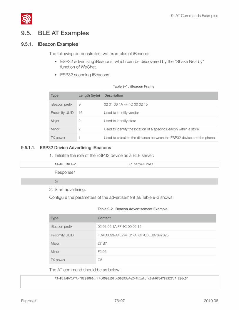
!
9. AT Commands Examples
9.5. BLE AT Examples 9.5.1. iBeacon Examples
The following demonstrates two examples of iBeacon:
• ESP32 advertising iBeacons, which can be discovered by the “Shake Nearby” function of WeChat.
• ESP32 scanning iBeacons.
9.5.1.1. ESP32 Device Advertising iBeacons
1. Initialize the role of the ESP32 device as a BLE server:
AT+BLEINIT=2//serverrole
Response:
OK
2. Start advertising.
Configure the parameters of the advertisement as Table 9-2 shows:
The AT command should be as below:
AT+BLEADVDATA="0201061aff4c000215fda50693a4e24fb1afcfc6eb0764782527b7f206c5"
Table 9-1. iBeacon Frame
Type Length (byte) Description
iBeacon prefix 9 02 01 06 1A FF 4C 00 02 15
Proximity UUID 16 Used to identify vendor
Major 2 Used to identify store
Minor 2 Used to identify the location of a specific Beacon within a store
TX power 1 Used to calculate the distance between the ESP32 device and the phone
Table 9-2. iBeacon Advertisement Example
Type Content
iBeacon prefix 02 01 06 1A FF 4C 00 02 15
Proximity UUID FDA50693-A4E2-4FB1-AFCF-C6EB07647825
Major 27 B7
Minor F2 06
TX power C5
Espressif ! /!76 97 2019.06

!
9. AT Commands Examples
Response:
OK
Start advertising:
AT+BLEADVSTART
Response:
OK
Open WeChat on your mobile phone and then select “Shake Nearby” to discover the ESP32 device that is advertising, as shown in Figure 9-1.
! Figure 9-1. “Shake Nearby” on WeChat
9.5.1.2. ESP32 Device Scanning for iBeacons
Not only can the ESP32 device transmits iBeacons, but it can also work as a BLE client that scans for iBeacons and gets the advertisement data which can then be parsed by the host MCU.
1. Initialize the role of the ESP32 device as a BLE client:
AT+BLEINIT=1//clientrole
⚠ Notice:
If the ESP32 device has already been initialized as a BLE server, you need to call AT+BLEINIT=0 to de-init it first, and then re-init it as a BLE client.
Espressif ! /!77 97 2019.06

!
9. AT Commands Examples
Response:
OK
2. Enable a scanning for three seconds:
AT+BLESCAN=1,3
Response:
OK
You will get a scanning result that looks like:
+BLESCAN:24:0a:c4:02:10:0e,-33,0201061aff4c000215fda50693a4e24fb1afcfc6eb0764782527b7f206c5,
+BLESCAN:24:0a:c4:01:4d:fe,-74,02010207097a4f68664b43020aeb051220004000,
+BLESCAN:24:0a:c4:02:10:0e,-33,0201061aff4c000215fda50693a4e24fb1afcfc6eb0764782527b7f206c5,
The result shows the advertisement that has been configured in Section 9.5.1.1. Then, the host MCU can parse the data whose frame is shown in Table 9-1.
9.5.2. BLE Communication Examples
9.5.2.1. Basic Communication
Below is an example of using two ESP32 modules, one as a BLE server (hereafter named "ESP32 Server") and the other one as a BLE client (hereafter named "ESP32 Client"). The example shows how to use BLE functions with AT commands.
1. BLE initialization:
• ESP32 Server:
AT+BLEINIT=2//serverrole
Response:
OK
- Create services.
AT+BLEGATTSSRVCRE
Response:
OK
- Start services.
AT+BLEGATTSSRVSTART
⚠ Notice:
The ESP32 Server needs to download a "service bin" into Flash to provide BLE services.
• To learn how to generate a "service bin", please refer to esp32-at/tools/readme.md.
• The download address of the "service bin" is the address of "ble_data" in esp32-at/at_customize.csv.
Espressif ! /!78 97 2019.06

!
9. AT Commands Examples
Response:
OK
• ESP32 Client:
AT+BLEINIT=1//clientrole
Response:
OK
2. Establish BLE connection:
• ESP32 Server:
- Query the BLE address. For example, if the address is "24:0a:c4:03:f4:d6".
AT+BLEADDR?//getserver'sBLEaddress
Response:
+BLEADDR:24:0a:c4:03:f4:d6
OK
- Configure parameters of advertisements. This is optional, though. If you do not configure the parameters of advertisements, default parameters will be applied.
AT+BLEADVPARAM=32,64,0,0,7
Response:
OK
- Configure advertisement data:
AT+BLEADVDATA="0201060B09457370726573736966030302A0"
/*Theadvdatais
*020106//<length>,<type>,<data>
*0A09457370726573736966//<length>,<type>,<data>
*030302A0//<length>,<type>,<data>
*/
Response:
OK
If you do not configure the advertisement data, then the payload will be empty when scanned.
You can also configure the response data of the scanning (ScanRspData):
AT+BLESCANRSPDATA="0201060B09457370726573736966030302A0"
OK
The ScanRspData can be discovered in an active scan.
- Start advertising.
Espressif ! /!79 97 2019.06

!
9. AT Commands Examples
AT+BLEADVSTART
Response:
OK
• ESP32 Client:
- Configure the scanning parameters. This is optional, though. For example, in the active-scan mode, the command is as follows:
AT+BLESCANPARAM=1,0,0,100,50
Response:
OK
- Start scanning.
AT+BLESCAN=1,3
Response:
+BLESCAN:<BLEaddress>,<rssi>,<adv_data>,<scan_rsp_data>
OK
- Establish the BLE connection, when the server is scanned successfully.
AT+BLECONN=0,"24:0a:c4:03:f4:d6"
Response:
OK
+BLECONN:0,"24:0a:c4:03:f4:d6"
- Update the connection parameters:
AT+BLECONNPARAM=0,30,30,0,600
OK
You can also query the result:
AT+BLECONNPARAM?
+BLECONNPARAM:0,30,30,30,0,600
OK
- Set the Maximum Transmission Unit (MTU)
The client can initiate an Exchange MTU Request after the connection has been established:
📖 Notes:
• If the BLE connection is established successfully, it will prompt +BLECONN:<conn_index>,<remote_BLE_address>
• If the BLE connection is broken, it will prompt +BLEDISCONN:<conn_index>,<remote_BLE_address>
Espressif ! /!80 97 2019.06

!
9. AT Commands Examples
AT+BLECFGMTU=0,200
OK
You can also query the result:
AT+BLECFGMTU?
+BLECFGMTU:0,200
OK
3. Read/Write a characteristic:
• ESP32 Server:
- Discover local services.
AT+BLEGATTSSRV?
Response:
+BLEGATTSSRV:1,1,0xA002,1
OK
- Discover characteristics.
AT+BLEGATTSCHAR?
Response:
+BLEGATTSCHAR:"char",1,1,0xC300
+BLEGATTSCHAR:"desc",1,1,1
+BLEGATTSCHAR:"char",1,2,0xC301
+BLEGATTSCHAR:"desc",1,2,1
+BLEGATTSCHAR:"char",1,3,0xC302
+BLEGATTSCHAR:"desc",1,3,1
OK
• ESP32 Client:
- Discover services:
AT+BLEGATTCPRIMSRV=0
Response:
+BLEGATTCPRIMSRV:0,1,0x1801,1
+BLEGATTCPRIMSRV:0,2,0x1800,1
+BLEGATTCPRIMSRV:0,3,0xA002,1
OK
Espressif ! /!81 97 2019.06

!
9. AT Commands Examples
- Discover characteristics.
AT+BLEGATTCCHAR=0,3
Response:
+BLEGATTCCHAR:"char",0,3,1,0xC300,2
+BLEGATTCCHAR:"desc",0,3,1,1,0x2901
+BLEGATTCCHAR:"char",0,3,2,0xC301,2
+BLEGATTCCHAR:"desc",0,3,2,1,0x2901
+BLEGATTCCHAR:"char",0,3,3,0xC302,8
+BLEGATTCCHAR:"desc",0,3,3,1,0x2901
+BLEGATTCCHAR:"char",0,3,4,0xC303,4
+BLEGATTCCHAR:"desc",0,3,4,1,0x2901
+BLEGATTCCHAR:"char",0,3,5,0xC304,8
+BLEGATTCCHAR:"char",0,3,6,0xC305,16
+BLEGATTCCHAR:"desc",0,3,6,1,0x2902
+BLEGATTCCHAR:"char",0,3,7,0xC306,32
+BLEGATTCCHAR:"desc",0,3,7,1,0x2902
OK
- Read a characteristic. Please note that the target characteristic's properties have to include the read operation.
AT+BLEGATTCRD=0,3,1
Response:
+BLEGATTCRD:0,1,30
OK
- Write a characteristic. Please note that the target characteristic's properties have to include the write operation.
AT+BLEGATTCWR=0,3,3,,2
Response:
⚠ Notice:
• When discovering services, the ESP32 Client will get two more default services (UUID:0x1800 and 0x1801) than what the ESP32 Server will get.
• So, for the same service, the <srv_index> received by the ESP32 Client equals the <srv_index> received by ESP32 Server + 2.
• For example, the <srv_index> of the above-mentioned service, 0xA002, is 3 when the ESP32 Client is in the process of discovering services. But if the ESP32 Server tries to discover it with command AT+BLEGATTSSRV?, the <srv_index> will be 1.
📖 Note:
If the ESP32 Client reads the characteristic successfully, message +READ:<conn_index>,<remoteBLEaddress> will be prompted on the ESP32 Server side.
Espressif ! /!82 97 2019.06

!
9. AT Commands Examples
> //waitingfordata
OK
4. Notify of a characteristic:
• ESP32 Client:
- Configure the characteristic's descriptor. Please note that the target characteristic's properties have to include notifications.
AT+BLEGATTCWR=0,3,6,1,2
Response:
> //waitingfordata,shouldinputHEXstring"01"here
OK
• ESP32 Server:
- Notify of a characteristic. Please note that the target characteristic's properties have to include notifications.
AT+BLEGATTSNTFY=0,1,6,3
Response:
> //waitingfordata
OK
5. Indicate a characteristic:
• ESP32 Client:
📖 Note:
If the ESP32 Client writes the characteristic successfully, message +WRITE:<conn_index>,<srv_index>,<char_index>,[<desc_index>],<len>,<value> will be prompted on the ESP32 Server side.
📖 Note:
If the ESP32 Client writes the descriptor successfully, message +WRITE:<conn_index>,<srv_index>,<char_index>,<desc_index>,<len>,<value> will be prompted on the ESP32 Server side.
📖 Note:
• If the ESP32 Client receives the notification, it will prompt message +NOTIFY:<conn_index>,<srv_index>,<char_index>,<len>,<value>.
• For the same service, the <srv_index> on the ESP32 Client side equals the <srv_index> on the ESP32 Server side + 2.
Espressif ! /!83 97 2019.06

!
9. AT Commands Examples
- Configure the characteristic's descriptor. Please note that the target characteristic's property has to support the indicate operation.
AT+BLEGATTCWR=0,3,7,1,2
Response:
> //waitingforserialdata,shouldinputHEXstring"02"here
OK
• ESP32 Server:
- Indicate characteristic. Please note that the target characteristic's property has to support the indicate operation.
AT+BLEGATTSIND=0,1,7,3
Response:
> //waitingforserialdata
OK
9.5.2.2. UART-BLE Passthrough Mode
Below is an example of using two ESP32 modules: one as a BLE server (hereafter named as "ESP32 Server") and the other one as a BLE client (hereafter named as "ESP32 Client"). The example shows how to build BLE SPP (Serial Port Profile, UART-BLE passthrough mode) with AT commands.
1. BLE initialization:
• ESP32 Server:
- BLE server initialization: AT+BLEINIT=2//serverrole
📖 Note:
If the ESP32 Client writes the descriptor successfully, message +WRITE:<conn_index>,<srv_index>,<char_index>,<desc_index>,<len>,<value> will be prompted on the ESP32 Server side.
📖 Note:
• If the ESP32 Client receives the indication, it will prompt message +INDICATE:<conn_index>,<srv_index>,<char_index>,<len>,<value>
• For the same service, the <srv_index> on the ESP32 Client side equals the <srv_index> on the ESP32 Server side + 2.
⚠ Notice:
Download the service bin into the flash of the ESP32 Server.
• On how to generate a service bin, please refer to esp32-at/tools/readme.md.
• The download address of the "service bin" is the address of "ble_data" in esp32-at/at_customize.csv.
Espressif ! /!84 97 2019.06

!
9. AT Commands Examples
Response:
OK
- Create services:
AT+BLEGATTSSRVCRE
Response:
OK
- Start services:
AT+BLEGATTSSRVSTART
Response:
OK
• ESP32 Client:
AT+BLEINIT=1//clientrole
Response:
OK
2. Establish BLE connection:
• ESP32 Server:
- Query the BLE address. The following section takes "24:0a:c4:03:f4:d6" as a example.
AT+BLEADDR?//getserver'sBLEaddress
Response:
+BLEADDR:24:0a:c4:03:f4:d6
OK
- Configure advertisement data (optional). Without the configuration, the payload of the broadcasting packet will be empty.
AT+BLEADVDATA="0201060B09457370726573736966030302A0"
/*Theadvdatais
*020106//<length>,<type>,<data>
*0A09457370726573736966//<length>,<type>,<data>
*030302A0//<length>,<type>,<data>
*/
Response:
OK
Espressif ! /!85 97 2019.06

!
9. AT Commands Examples
- Start advertising.
AT+BLEADVSTART
Response:
+BLEADDR:24:0a:c4:03:f4:d6
OK
• ESP32 Client:
- Start scanning:
AT+BLESCAN=1,3
Response:
+BLESCAN:<BLEaddress>,<rssi>,<adv_data>,<scan_rsp_data>
OK
- Establish the BLE connection, after the server is scanned successfully.
AT+BLECONN=0,"24:0a:c4:03:f4:d6"
Response:
OK
+BLECONN:0,"24:0a:c4:03:f4:d6"
3. Discover Services:
• ESP32 Server:
- Discover local services.
AT+BLEGATTSSRV?
Response:
+BLEGATTSSRV:1,1,0xA002,1
OK
- Discover characteristics:
AT+BLEGATTSCHAR?
Response:
📖 Notes:
• If the BLE connection is established successfully, the message +BLECONN:<conn_index>,<remote_BLE_address> will appear.
• If the BLE connection is broken, the message +BLEDISCONN:<conn_index>,<remote_BLE_address> will appear.
Espressif ! /!86 97 2019.06

!
9. AT Commands Examples
+BLEGATTSCHAR:"char",1,1,0xC300
+BLEGATTSCHAR:"desc",1,1,1
+BLEGATTSCHAR:"char",1,2,0xC301
+BLEGATTSCHAR:"desc",1,2,1
+BLEGATTSCHAR:"char",1,3,0xC302
+BLEGATTSCHAR:"desc",1,3,1
OK
• ESP32 Client:
- Discover services:
AT+BLEGATTCPRIMSRV=0
Response:
+BLEGATTCPRIMSRV:0,1,0x1801,1
+BLEGATTCPRIMSRV:0,2,0x1800,1
+BLEGATTCPRIMSRV:0,3,0xA002,1
OK
- Discover characteristics.
AT+BLEGATTCCHAR=0,3
Response:
+BLEGATTCCHAR:"char",0,3,1,0xC300,2
+BLEGATTCCHAR:"desc",0,3,1,1,0x2901
+BLEGATTCCHAR:"char",0,3,2,0xC301,2
+BLEGATTCCHAR:"desc",0,3,2,1,0x2901
+BLEGATTCCHAR:"char",0,3,3,0xC302,8
+BLEGATTCCHAR:"desc",0,3,3,1,0x2901
+BLEGATTCCHAR:"char",0,3,4,0xC303,4
+BLEGATTCCHAR:"desc",0,3,4,1,0x2901
+BLEGATTCCHAR:"char",0,3,5,0xC304,8
+BLEGATTCCHAR:"char",0,3,6,0xC305,16
+BLEGATTCCHAR:"desc",0,3,6,1,0x2902
+BLEGATTCCHAR:"char",0,3,7,0xC306,32
+BLEGATTCCHAR:"desc",0,3,7,1,0x2902
⚠ Notice:
• When discovering services, the ESP32 Client will get two more default services (UUID:0x1800 and 0x1801) than what the ESP32 Server will get.
• So, for the same service, the <srv_index> received by the ESP32 Client equals the <srv_index> received by ESP32 Server plus 2.
• For example, the <srv_index> of the above-mentioned service, 0xA002, is 3 when the ESP32 Client is in the process of discovering services. But if the ESP32 Server tries to discover it with command AT+BLEGATTSSRV?, the <srv_index> will be 1.
Espressif ! /!87 97 2019.06

!
9. AT Commands Examples
OK
4. Configure BLE SPP:
• ESP32 Client:
- Set a characteristic that enables writing permission to TX channel for sending data. Set another characteristic that supports notification or indication to RX channel for receiving data.
AT+BLESPPCFG=1,3,5,3,7
Response:
OK
- Enable BLE SPP:
AT+BLESPP
Response:
OK
>//waitingforserialdata
• ESP32 Server:
- Set a characteristic that supports notification or indication to TX channel for sending data. Set another characteristic that enables writing permission to RX channel for receiving data.
AT+BLESPPCFG=1,1,7,1,5
Response:
OK
- Enable BLE SPP:
AT+BLESPP
Response:
OK
>//waitingforserialdata
📖 Note:
After ESP32 Client enabling BLE SPP, data received from serial port will be transmitted to the BLE server directly.
Espressif ! /!88 97 2019.06

!
9. AT Commands Examples
9.5.2.3. Usage Scenarios
1. Bluetooth networking
BLE can be used to transfer the Wi-Fi SSID and Password in a Bluetooth network.
• Use AT+BLEGATTCWR for the client to pass on the SSID and password to the server.
• Use AT+BLEGATTSNTFY for the server to pass on the SSID and password to the client.
Details can be found in Section 9.5.2.1.
2. Transparent data transmission
The ESP32 AT does not support transparent data transmission over BLE for the time being. However, users can use that basic data-transmission method to simulate the transparent data transmission process where Host MCU can filter the data information.
• Call AT+BLEGATTCWR continuously for the client to transfer data to the server.
• Call AT+BLEGATTSNTFY continuously for the server to transfer data to the client.
Details can be found in Section 9.5.2.1.
3. OTA firmware upgrade
OTA firmware upgrade can also be implemented over BLE.
📖 Notes:
• After ESP32 Server enables BLE SPP, the data received from serial port will be transmitted to the BLE client directly.
• If the ESP32 Client does not enable BLE SPP first, or uses other device as BLE client, then the BLE client needs to listen to the notification or indication first. For example, if the ESP32 Client does not enable BLE SPP first, then it should enable listening with command AT+BLEGATTCWR=0,3,7,1,1 first for the ESP32 Server to transmit successfully.
• For the same service, the <srv_index> on the ESP32 Client side equals the <srv_index> on the ESP32 Server side plus 2.
Espressif ! /!89 97 2019.06

!
10. OTA Update
10. OTA Update The following steps guide the users in creating a device on iot.espressif.cn and updating the OTA BIN on it.
1. Open the website iot.espressif.cn. If using SSL OTA, it should be https://iot.espressif.cn.
!
2. Click "Join" in the upper right corner of the webpage, and enter your name, email address, and password.
!
3. Click on "Device" in the upper right corner of the webpage, and click on "Create" to create a device.
Espressif ! /!90 97 2019.06

!
10. OTA Update
!
!
4. A key is generated when the device is successfully created, as the figure below shows.
Espressif ! /!91 97 2019.06

!
10. OTA Update
!
5. Use the key to compile your own OTA BIN. The process of configuring the AT OTA token key is as follows:
!
Espressif ! /!92 97 2019.06

!
10. OTA Update
!
!
6. Click on "Product" to enter the webpage, as shown below. Click on the device created. Enter version and corename under "ROM Deploy". Rename the BIN compiled in Step 5 as "ota.bin" and save the configuration.
⚠ Notice:
If using SSL OTA, the option "OTA based upon ssl" should be selected.
Espressif ! /!93 97 2019.06

!
10. OTA Update
!
!
7. Click on the ota.bin to save it as the current version.
Espressif ! /!94 97 2019.06

!
10. OTA Update
!
8. Run the command AT+CIUPDATE. If the network is connected, OTA update w.
Espressif ! /!95 97 2019.06

!
11. Q & A
11. Q & A If you have any questions about the execution of AT commands, please contact us via Espressif Technical Inquiries. Please describe the issues that you might encounter, including any relevant details, as follows:
• AT Version information or AT Command: You can use command AT+GMR to acquire information on your current AT command version.
• Hardware Module information: for example, ESP-WROOM-32.
• Screenshot of the test steps, for example:
!
• If possible, please provide the printed log information, such as:
GuruMeditationErroroftypeStoreProhibitedoccurredoncore0.Exceptionwasunhandled.
Registerdump:
PC:40135735PS:00060f30A0:800f913bA1:3ffd66c0
A2:00000000A3:3ffd6828A4:00000b68A5:b33f0000
A6:b33fffffA7:3ffb004cA8:00000003A9:3ffd66a0
A10:3ffd6828A11:00000b69A12:00060020A13:3ffc2d30
A14:00000003A15:00060023SAR:00000000EXCCAUSE:0000001d
EXCVADDR:00000038LBEG:00000000LEND:00000000LCOUNT:00000000
Rebooting...
Espressif ! /!96 97 2019.06

Disclaimer and Copyright Notice Information in this document, including URL references, is subject to change without notice. THIS DOCUMENT IS PROVIDED AS IS WITH NO WARRANTIES WHATSOEVER, INCLUDING ANY WARRANTY OF MERCHANTABILITY, NON-INFRINGEMENT, FITNESS FOR ANY PARTICULAR PURPOSE, OR ANY WARRANTY OTHERWISE ARISING OUT OF ANY PROPOSAL, SPECIFICATION OR SAMPLE. All liability, including liability for infringement of any proprietary rights, relating to the use of information in this document, is disclaimed. No licenses express or implied, by estoppel or otherwise, to any intellectual property rights are granted herein. The Wi-Fi Alliance Member logo is a trademark of the Wi-Fi Alliance. The Bluetooth logo is a registered trademark of Bluetooth SIG. All trade names, trademarks and registered trademarks mentioned in this document are property of their respective owners, and are hereby acknowledged. Copyright © 2019 Espressif Inc. All rights reserved.
Espressif IOT Teamwww.espressif.com
�