Embed Size (px)
Citation preview

ESO 210
Introduction to Electrical Engineering Lectures-32
Polyphase (3-phase) Induction Motor

2
Construction of a three-phase induction motor
Squirrel cage / wound rotors

3
Principle of operation of a three-phase induction motor
When a three-phase supply is connected to the stator windings, a rotating magnetic field is produced. As the magnetic flux cuts a bar (or conductor) on the rotor, an e.m.f. is induced in it and since it is joined, via the end conducting rings, to another bar one pole pitch away, a current flows in the bars. The magnetic field associated with this current flowing in the bars interacts with the rotating magnetic field and a force is produced, tending to turn the rotor in the same direction as the rotating magnetic field, Similar forces are applied to all the conductors on the rotor, so that a torque is produced causing the rotor to rotate.

4
The same can be better understood my Lenz’s Law which says: An induced Electro Motive Force (emf) always gives rise to a current whose magnetic field opposes the original change in Magnetic Flux.

5
Slip The force exerted by the rotor bars causes the rotor to turn in the direction of the rotating magnetic field. (As per the Lenz’s Law) The rotor speed increases from standstill to match the speed of the rotating magnetic. However rotor speed remains less than that of the magnetic field and the difference in this speed is termed as Slip of Slip speed. If the rotor runs at the same speed as the rotating magnetic field, no e.m.f.’s are induced in the rotor, hence there is no force on them and no torque on the rotor. Thus the rotor slows down. For this reason the rotor can never run at synchronous speed. When there is no load on the rotor, the resistive forces due to windage and bearing friction are small and the rotor runs very nearly at synchronous speed. As the rotor is loaded, the speed falls and this causes an increase in the frequency of the induced e.m.f.’s in the rotor bars and hence the rotor current, force and torque increase. The difference between the rotor speed, nr , and the synchronous speed, ns, is called the slip speed, i.e.

6

7

8

9

Induction Motor: working principle
10

11
Rotor e.m.f. and frequency
When an induction motor is stationary, the stator and rotor windings form the equivalent of a transformer as shown in Figure below.
The rotor e.m.f. at standstill is given by
where E1 is the supply voltage per phase to the stator. When an induction motor is running(i.e. the rotor is rotating), the induced e.m.f. in the rotor is less since the relative movement between conductors and the rotating field is less. The induced e.m.f. is proportional to the relative movement, hence it must be proportional to the slip, s
12
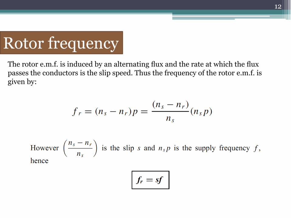
Rotor frequency The rotor e.m.f. is induced by an alternating flux and the rate at which the flux passes the conductors is the slip speed. Thus the frequency of the rotor e.m.f. is given by:

13

14
Rotor impedance and current
The rotor resistance R2 is unaffected by frequency or slip, and hence remains constant.
Rotor reactance varies with the frequency of the rotor current.

15

16
The equivalent circuit of an Induction motor:

17
Rotor copper loss

18
Induction motor losses and efficiency

19

20

21
Torque equation for an induction motor

22
Under normal conditions, the supply voltage is usually constant, hence

23

24

25

26
Induction motor torque–speed characteristics

Inductor Motor 27

28
Starting methods for induction motors Squirrel-cage rotor:
(i) Direct-on-line starting (DOL) With this method, starting current is high and may cause interference with supplies to other consumers.
(ii) Auto transformer starting With this method, an auto transformer is used to reduce the stator voltage, E1, and thus the starting current. However, the starting torque is seriously reduced so the voltage is reduced only sufficiently to give the required reduction of the starting current. A typical arrangement is shown in Figure below. A double-throw switch connects the auto transformer in circuit for starting, and when the motor is up to speed the switch is moved to the run position which connects the supply directly to the motor.

29
(iii) Star-delta starting With this method, for starting, the connections to the stator phase winding are star-connected, so that the voltage across each phase winding is 1/√3 (i.e. 0.577) of the line voltage. For running, the windings are switched to delta-connection. A typical arrangement is shown in Figure below. This method of starting is less expensive than by auto transformer.

30
Wound rotor When starting on load is necessary, a wound rotor induction motor must be used. This is because maximum torque at starting can be obtained by adding external resistance to the rotor circuit via slip rings. A face-plate type starter is used, and as the resistance is gradually reduced, the machine characteristics at each stage will be similar to Q, S, R and P. At each resistance step, the motor operation will transfer from one characteristic to the next so that the overall starting characteristic will be as shown by the bold line in Figure below. For very large induction motors, very gradual and smooth starting is achieved by a liquid type resistance.
31
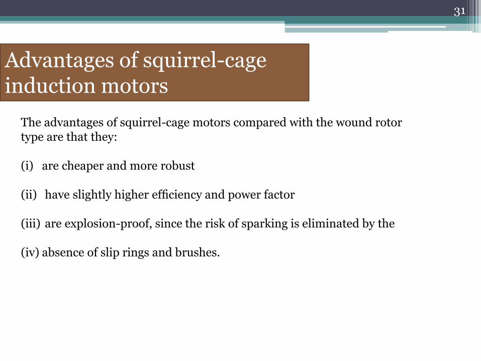
Advantages of squirrel-cage induction motors
The advantages of squirrel-cage motors compared with the wound rotor type are that they: (i) are cheaper and more robust
(ii) have slightly higher efficiency and power factor
(iii) are explosion-proof, since the risk of sparking is eliminated by the
(iv) absence of slip rings and brushes.

32
Advantages of wound rotor induction motor
The advantages of the wound rotor motor compared with the cage type are that they: (i) have a much higher starting torque
(ii) have a much lower starting current (iii) have a means of varying speed by use of external rotor resistance.

33
The advantages of squirrel-cage and wound rotor induction motors are combined in the double cage induction motor. This type of induction motor is specially constructed with the rotor having two cages, one inside the other. The outer cage has high resistance conductors so that maximum torque is achieved at or near starting. The inner cage has normal low resistance copper conductors but high reactance since it is embedded deep in the iron core. The torque-speed characteristic of the inner cage is that of a normal induction motor, as shown in Figure below. At starting, the outer cage produces the torque, but when running the inner cage produces the torque. The combined characteristic of inner and outer cages is shown in Figure below. The double cage induction motor is highly efficient when running.
Double cage induction motor

34
Single-phase Induction Motor

35

36
The winding used normally in the stator of the single-phase induction motor (IM) is a distributed one. The rotor is of squirrel cage type, which is a cheap one, as the rating of this type of motor is low, unlike that for a three-phase IM. As the stator winding is fed from a single-phase supply, the flux in the air gap is alternating only, not a synchronously rotating one produced by a poly-phase (may be two- or three-) winding in the stator of IM. This type of alternating field cannot produce a torque ( (T0)st=0.0), if the rotor is stationery ( ωr=0.0 ). So, a single-phase IM is not self-starting, unlike a three-phase one. However, as shown later, if the rotor is initially given some torque in either direction (ωr≠0.0), then immediately a torque is produced in the motor. The motor then accelerates to its final speed, which is lower than its synchronous speed. This is now explained using double field revolving theory.

37

38

39
40

41
A typical shaded-pole motor with a cage rotor is shown in Fig. above. This is a single- phase induction motor, with main winding in the stator. A small portion of each pole is covered with a short-circuited, single-turn copper coil called the shading coil. The sinusoidally varying flux created by ac (single-phase) excitation of the main winding induces emf in the shading coil. As a result, induced currents flow in the shading coil producing their own flux in the shaded portion of the pole.
The reversal of the direction of rotation, where desired, can be achieved by providing two shading coils, one on each end of every pole, and by open-circuiting one set of shading coils and by short-circuiting the other set.

42
Force of attraction between stator poles and rotor poles - resulting in production of torque in clockwise direction

43
Methods of starting synchronous motor

44

45
A phasor diagram shown in previous slide, illustrates the method of determining the counter EMF which is obtained from the phasor equation;
The phase angle δ between the terminal voltage VT and the excitation voltage Ef in is usually termed the torque angle. The torque angle is also called the load angle or power angle.

46

47
Home Assignmen-3
Explain the contruction and working of a Stepper motor
Synchonous motor power equation and V curves
Last date April 21


![11 S.. · 11 s.. aq.. s.. 11.2 s.. aq.. 11.2.1 s 37 aq.. [nm] ... 44.22 155 210 260 155 210 260 155 210 260 155 210 260 47.32 155 210 260 155 210 260 155 210 260 155 210 260](https://img.dokumen.tips/doc/110x75/5b189dcc7f8b9a19258bfc6f/11-s-11-s-aq-s-112-s-aq-1121-s-37-aq-nm-4422-155-210.jpg)