Embed Size (px)
Citation preview

CHAPTER ONE
INTRODUCTION
1.1 Concepts of Power Factor Correction
Power Factor is a characteristic of alternating current, and can be defined as the ratio of
working power to total power. Alternating current has the following components
Real Power: Power which produces work (kW)
Available:
Power-
Power delivered or total volt amps (kVA)
Reactive Power-Power needed to generate magnetic fields required for the operation of
Inductive electrical equipment, such as motors and transformers, therefore
must take from the electrical distribution system more current than is
necessary to perform the work involved. (kVAR) No useful work is
performed with reactive power.
Therefore the unit less Power Factor is obtained from
Power Factor = Real Power = kW
Available
Power
kVA
Power Factor is generally represented as a percentage or a decimal. Perfect power factor,
often referred to as unity power factor would be 100% or 1.0.
1.2. What is Power Factor Correction?
All flowing current causes losses in the supply and distribution system. A load with a power
factor of 1.0 result is the most efficient loading for the supply and a load with a power factor
of 0.6 will have much higher losses in the supply system. These loses have to be paid for,
and result in higher utility bills. It is possible to modify the supply and distribution system
to bring the power factor closer to unity. This is called power factor correction.

1.3 Correcting Power Factor
The simplest form of power factor correction, sometimes referred to as static correction, is by
the addition of capacitors in parallel with the connected inductive load. The resulting capacitive
current is a leading current and is used to cancel the lagging inductive current flowing from the
supply. The capacitors can be applied at the starter or the switchboard or at the distribution panel.
Note that power factor correction should not be used when a motor is controlled by a variable
speed drive. Rather than correcting each individual load, the total current supplied to the
distribution board can be monitored by a controller which switches capacitor banks to maintain
the power factor at its predetermined setting. The controller switching in capacitors as new loads
come on line, and switching out capacitors as loads go off line. This type of correction is
sometimes referred to as bulk correction.
1.1.1. General objective
Specific objective
Significance of the project
The customer utility bill will be smaller.
Low power factor requires an increase in the electric utility’s generation and transmission
capacity to handle the reactive power component caused by inductive loads.
Utilities usually charge a penalty fee to customers with power factors less than 0.95.
The customer can avoid this additional fee by increasing his power factor.
The customer electrical system’s branch capacity will increase. Uncorrected power factor
will cause power losses in his distribution system.
The customer may experience voltage drops as power losses increase. Excessive voltage
drops can cause overheating and premature failure of motors and other inductive
equipment.
Installation of our equipment to furnish the non-productive current requirements of the
facility makes it possible to increase the plant's connected load as much as 20% without a

corresponding increase in the size of transformers, conductors and protective devices
servicing the load.
Improved voltage regulation due to reduced lower voltage drop.
By considering power factor correction at the design stage it is possible to reduce capital
investment through reduction in the size of transformers, switchgear and cable diameters
and the like
. Scope of the project
. Methodology

CHAPTER TWO
POWER FACTOR CORRECTION OF THREE PHASE
TRANSFORMER AND HARMONIC DESTORATION
2.1 power factor correction of three phase transformer
Transformers are electrical machines of primary importance; due to installation reasons they
often are in constant service. In particular, in the electrical plants constituted by different
transformation and supply substations it is advisable that power factor correction is carried out
by keeping into account the transformer reactive power so that an average power factor equal to
0.9 on the MV side is guaranteed. Generally speaking, the compensation power Qc in a
transformer having a rated Sr [kVA], shall not exceed the reactive power absorbed under
minimum reference load conditions. Deriving from the nameplate characteristics of the
transformer the percentage no-load current i0%, the percentage short-circuit voltage uk%, the iron
losses Pfe and the copper losses Pcu [kW], the required compensation power results to be about:
QC=√( I 0%
100.SR)
2
−PFE
2+KL
2√(U K %
100.SR)
2
−PCU
2≃( I 0%
100.S R)+K L
2+(UK %
100.S R)[ KVar ]
Where KL is the load factor, defined as the ratio between the minimum reference load and the
rated power of the transformer.
2.2 Harmonic Distortion:
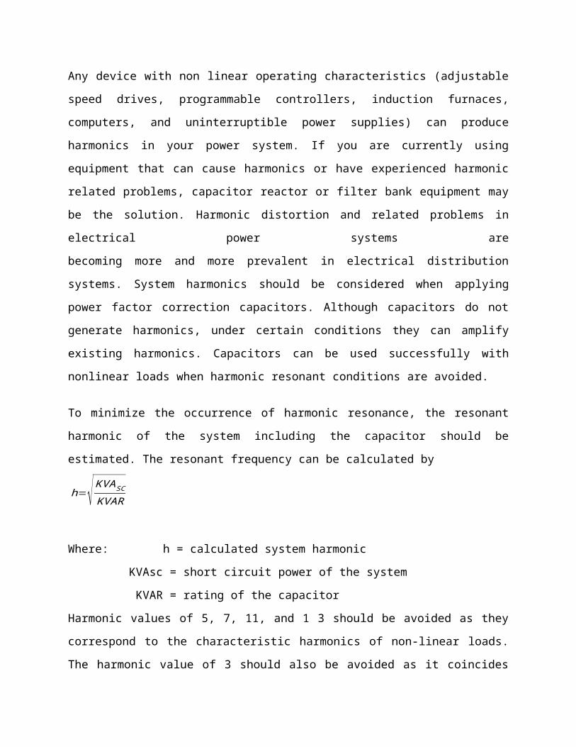
Any device with non linear operating characteristics (adjustable speed drives, programmable
controllers, induction furnaces, computers, and uninterruptible power supplies) can produce
harmonics in your power system. If you are currently using equipment that can cause harmonics
or have experienced harmonic related problems, capacitor reactor or filter bank equipment may
be the solution. Harmonic distortion and related problems in electrical power systems are
becoming more and more prevalent in electrical distribution systems. System harmonics should
be considered when applying power factor correction capacitors. Although capacitors do not

generate harmonics, under certain conditions they can amplify existing harmonics. Capacitors
can be used successfully with nonlinear loads when harmonic resonant conditions are avoided.
To minimize the occurrence of harmonic resonance, the resonant harmonic of the system
including the capacitor should be estimated. The resonant frequency can be calculated by
h=√ KVASC
KVAR
Where: h = calculated system harmonic
KVAsc = short circuit power of the system
KVAR = rating of the capacitor
Harmonic values of 5, 7, 11, and 1 3 should be avoided as they correspond to the characteristic
harmonics of non-linear loads. The harmonic value of 3 should also be avoided as it coincides
with harmonics produced during transformer energization and/or operation of the transformer
above rated voltage.
Once identified the resonant harmonics can be avoided in several ways:
1. Change the applied kVAR to avoid unwanted harmonics
Although this is the least expensive way to avoid resonant harmonics, it is not always successful
because typically some portion of the applied kVAR is switched on and off as load conditions
require. The calculation of system harmonics should be repeated for each level of compensation.
Adjusting the size of the capacitor(s) may be necessary to avoid the harmonic values.
2. Add harmonic filters
In order to filter harmonics at a specific site, tuned harmonic filters can be applied. A capacitor is
connected in series with an inductor such that the resonant frequency of the filter equals the
harmonic to be eliminated. Tuned filters should never be applied without a detailed analysis of
the Power Factor Correction system. The currents expected to flow in the filter are difficult to
predict and are a complex function of the system and load characteristics.

3. Add blocking inductors
Inductors added to the lines feeding the capacitor can be sized to block higher than 4th harmonic
currents. This method protects the capacitor from the harmonics but does not eliminate the
harmonics from the system. A system study is required to determine correct ratings for the
capacitor and inductors.
Fig 2.1
Problems Created by Harmonics
Excessive heating and failure of capacitors, capacitor fuses, transformers, motors,
fluorescent lighting ballasts, etc.
Nuisance tripping of circuit breaker or blown fuses
Presence of the third harmonic & multiples of the 3rd harmonic in neutral grounding
systems may require the derating of neutral conductors
Noise from harmonics that lead to erroneous operation of control system components
Damage to sensitive electronic equipment
Electronic communications interference
The following is a discussion of harmonics; the characteristics of the problem; and a discussion
of our solution:
2.1 Origins of Harmonic Distortion
The ever increasing demand of industry and commerce for stability, adjustability and accuracy of
control in electrical equipment led to the development of relatively low cost power diodes,
thrusters, SCRs and other power semi conductors. Now used widely in rectifier circuits for
U.P.S. systems, static converters and A.C. & D.C. motor control, these modern devices replace
the mercury arc rectifiers of earlier years and create new and challenging conditions for the
power engineer of today. Although solid state devices, such as the thruster, have brought
significant improvements in control designs and efficiency, they have the disadvantage of
producing harmonic currents. Harmonic currents can cause a disturbance on the supply network
and adversely affect the operation of other electrical equipment including power factor correction
capacitors.
We are concentrating our discussions on harmonic current sources associated with solid state
power electronics but there are actually many other sources of harmonic currents. These sources
can be grouped into three main areas:
1. Power electronic equipment: Variable speed drives (AC VFDÕs, DC drives, PWM
drives, etc.); UPS systems, rectifiers, switch mode power supplies, static converters,
thyristor systems, diode bridges, SCR controlled induction furnaces and SCR
controlled systems.
2. Arcing equipment: Arc furnaces, welders, lighting (mercury vapor, fluorescent)
3. Saturable devices: Transformers, motors, generators, etc. The harmonic amplitudes
on these devices are usually insignificant compared to power electronic and arcing
equipment, unless saturation occurs.
Transient problems are usually solved by installing suppression or isolation devices such as
surge capacitors, isolation transformers or M.O.V.s. These devices will help solve the transient
problems but will not affect the mitigation of low order harmonics or solve harmonic resonance
problems.
2.2. Harmonic Content
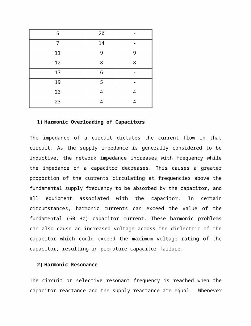
Thyristor and SCR converters are usually referred to by the number of DC current pulses they
produce each cycle. The most commonly used are 6 pulse and 12 pulse.

Table 2-1 Harmonic Content
ORDER OF HARMONICTYPICAL PERCENTAGE OF
HARMONIC CURRENT
- 6 Pulse 12 Pulse
1 100 100
5 20 -
7 14 -
11 9 9
12 8 8
17 6 -
19 5 -
23 4 4
23 4 4
1) Harmonic Overloading of Capacitors
The impedance of a circuit dictates the current flow in that circuit. As the supply impedance is
generally considered to be inductive, the network impedance increases with frequency while the
impedance of a capacitor decreases. This causes a greater proportion of the currents circulating at
frequencies above the fundamental supply frequency to be absorbed by the capacitor, and all
equipment associated with the capacitor. In certain circumstances, harmonic currents can exceed
the value of the fundamental (60 Hz) capacitor current. These harmonic problems can also cause
an increased voltage across the dielectric of the capacitor which could exceed the maximum
voltage rating of the capacitor, resulting in premature capacitor failure.
2) Harmonic Resonance
The circuit or selective resonant frequency is reached when the capacitor reactance and the
supply reactance are equal. Whenever power factor correction capacitors are applied to a
distribution network, which combines capacitance and inductance, there will always be a
frequency at which the capacitors are in parallel resonance with the supply. If this condition
occurs on, or close to, one of the harmonics generated by solid state control equipment, then

large harmonic currents can circulate between the supply network and the capacitor equipment.
These currents are limited only by the damping resistance in the circuit. Such currents will add to
the harmonic voltage disturbance in the network causing an increased voltage distortion. This
results in a higher voltage across the capacitor and excessive current through all capacitor
components. Resonance can occur on any frequency, but in general, the resonance we are
concerned with is on, or close to, the 5th, 7th, 11th and 13th harmonics for 6 pulse systems
3) Avoiding Resonance
There are a number of ways to avoid resonance when
installing capacitors. In larger systems it may be
possible to install them in a part of the system that will
not result in a parallel resonance with the supply.
Varying the kvar output rating of the capacitor bank
will alter the resonant frequency. With capacitor
switching there will be a different resonant frequency
for each step. Changing the number of switching steps
may avoid resonance at each step of switching
Fig 2.1 Filtering resonance
4) Overcoming Resonance
Resonance cannot be avoided, an alternative solution is required. A reactor must be connected in
series with each capacitor such that the capacitor/reactor combination is inductive at the critical
frequencies but capacitive at the fundamental frequency. To achieve this, the capacitor and series
connected reactor must have a tuning frequency below the lowest critical order of harmonic,
which is usually the 5th. This means the tuning frequency is in the range of 175 Hz to 270 Hz,
although the actual frequency will depend upon the magnitude and order of the harmonic
currents present. The addition of a reactor in the capacitor circuit increases the fundamental
voltage across the capacitor. Therefore, care should be taken when adding reactors to existing
capacitors.

Figure 2-2 Detuned capacitor/reactor system
5) Reduction of Harmonic Distortion
Harmonic currents can be significantly reduced in an electrical system by using a harmonic filter.
In its basic form, a filter consists of a capacitor connected in series with a reactor tuned to a
specific harmonic frequency. In theory, the impedance of the filter is zero at the tuning
frequency; therefore, the harmonic current is absorbed by the filter. This, together with the
natural resistance of the circuit, means that only a small level of harmonic current will flow in
the network.
2.3 Types of Filters
Effectiveness of any filter design depends on the reactive output of the filter, tuning accuracy
and the impedance of the network at the point of connection. Harmonics below the filter tuning
frequency will be amplified. The filter design is important to ensure that distortion is not
amplified to unacceptable levels. Where there are several harmonics present, a filter may reduce
some harmonics while increasing others. A filter for the 7th harmonic creates a parallel
resonance in the vicinity of the 5th harmonic with magnification of the existing 5th harmonic;
therefore, a 7th harmonic filter requires a 5th harmonic filter. Consequently, it is often necessary
to use a multiple filter design where each filter is tuned to a
different frequency.

Experience is extremely important in the design of such filters to ensure:
A) the most efficient and cost effective solution is selected;
B) No adverse interaction between the system and the filter.
Whenever load expansion is considered, the network is likely to change and existing filter
equipment should be evaluated in conjunction with the new load condition. It is not
recommended to have two or more filters tuned to the same frequency connected on the same
distribution system. Slight tuning differences may cause one filter to take a much larger share of
the harmonic distortion. Or, it may cause amplification of the harmonic order which the
equipment has been designed to reduce. When there is a need to vary the power factor correction
component of a harmonic filter, careful consideration of all load parameters is necessary.
2.3.1. Harmonic Analysis
The first step in solving harmonic related problems is to perform an analysis to determine the
specific needs of your electrical distribution system. To determine capacitor and filter
requirements, it is necessary to establish the impedance of the supply network and the value of
each harmonic current. Capacitor, reactor and filter bank equipment are then specified under
very detailed and stringent computer analysis to meet your needs.
The Harmonic Solution
The following three options to solve the problems associated with applying capacitors to systems
having harmonic distortion:
1. Apply the correct amount of capacitance (kvar) to the network to avoid resonance with the
source. This may be difficult, especially in automatic systems as the capacitance is always
changing. This solution usually means connecting less capacitance to the system than is
actually needed for optimum power factor correction.
2. Install reactors in series with capacitors to lower the resonance below critical order
harmonics; i.e., 5th, 7th, 11th & 13th. This design tunes the resonant frequency of the
system well below the 5th harmonic and is called a detuned filter bank. This solution
allows the capacitors to operate in a harmonic environment.
3. Filters are recommended if a problem exists with harmonic distortion before the
application of power factor correction, or if the harmonic distortion is above the limits
recommended in IEEE 519, Guide for Harmonic Control and Reactive Compensation of
Static Power Converters. (The recommended limits for voltage distortion in IEEE 519 are
presently 5% for general applications.) Tuned filters sized to reduce the harmonic
distortion at critical frequencies have the benefits of correcting the power factor and
improving the network power quality.
With our knowledge of harmonics, ABB Control provides a complete range of products from
individual capacitors, fixed banks and automatic banks, to power filter systems. All these
products utilize dry type low voltage ABB power factor correction capacitor elements which are
self-healing for internal faults.
To maintain stringent quality control standards, most control components found in ABB Control
automatic, reactor and filter capacitor bank products are also ABB products. These products
include contactors, circuit breakers, control relays, and disconnect switches, power factor relays
and push-button devices. ABB Capacitor Features & Services Every ABB Control low voltage
capacitor product incorporates our unique dry type design. Therefore, environmental and
personnel concerns associated with leakage or flammability of conventional oil-filled units are
eliminated.
2.3.2. How to Improve Power Factor without Causing Harmonic Problem?
Capacitors should be replaced by harmonic suppression filters (series combination of suitable
series reactor & capacitors) so that, It offers capacitive reactance at fundamental frequency for
necessary power factor correction. It offers inductive reactance at all higher order dominant
harmonic frequencies to avoid resonance. Its self series resonance frequency “f R” do not
coincide with predominant harmonics. Network With Harmonic Filters No resonance at

harmonic frequencies as filter is inductive at such frequencies Harmonic currents flow towards
Grid, as it offers least impedance compared to filter Predominantly fundamental current flows
through Capacitors Moderate THD (V) in the Bus No harmonic overloading of Capacitors.

CHAPTER THREE
LOW VOLTAGE MULTISTEP FILTER BANK SPECFICATION
3.1. General Requirement and Rating
a) Furnish one (1) metal enclosed harmonic filter banks tuned to the 4.2nd harmonic
as follows: 9000kVAr effective with one (1) fixed stage of 4000kVAr and two (2)
automatically switched stages of 2500kVAr each, 13,800Volts, 95kVbil, 3phase, 50
Hertz, Ungrounded Wye Connected, indoor/outdoor.
b) The equipment shall be factory assembled and tested prior to shipment and, in
general, consist of the following:
1. Incoming Section with provisions for the following:
a) Incoming Line Lugs
b) Group-Operated Disconnect Switch
c) Surge Arrestors
d) Potential Transformers
e) Control Power Transformers
f) Current Transformers
2. Capacitor Section with provisions for the following:
a) Vacuum Switches: three (3) single-phase 15kV, 200A vacuum switches per
switched
b) Stage.
c) Capacitor Fuses: one (1) per capacitor
d) Iron Core Reactors
e) Main Bus
f) Ground Bus
g) Ground Switch
h) Heating and Ventilation Equipment
3. Control Section
a) Controller
b) Relays

c) Lights
3.2. Enclosure
A) General
1. Enclosure to be pad mounted self supporting steel structure of a fully welded
construction with necessary provisions for ventilation and handling. It shall be
fabricated from diameter 11 gauge minimum Standard sheet metal. The enclosure
shall be constructed such that it can be moved by a crane or forklift and lifted, slid or
rolled into place on a pad without damage to any portion of the enclosure or its
contents.
2. There shall be thermostatically controlled heaters for condensation control located in
all non ventilated compartments.
3. The enclosure shall utilize a highly corrosion-resistant finishing system. All surfaces
shall undergo a thorough pretreatment process before any protective coatings are
applied.
4. Protective coatings shall be applied after pretreatment that resist corrosion and
protect the steel enclosure.
5. The enclosure shall have hinged doors with padlock provisions to provide access to
all components of the capacitor bank. The doors shall have 3-point latches. Door
stops shall be provided on all doors to limit the door swing to 90° and prevent the
doors from being blown shut. Removable bolted panels shall also be provided for
maintenance and access to all components.
6. Doors shall feature bulkhead style doors and all-welded construction for long-term
durability and weatherproof operation.
7. Viewing windows to permit visual observation of the position of the disconnect
switch and ground switch are to be provided.
8. A structural steel base is to be provided. The entire base is to be undercoated with a
black, phenolic coating for additional protection against environmental conditions.
9. As evidence of durability, enclosure and construction will be certified by a
registered professional engineer to comply with Seismic Zone 4 requirements.

10. The enclosure shall be equipped with vents for ventilation. Vents will be provided
with aluminum filters to prevent dust and insect entry. Filters are to be removable
for cleaning purposes.
11. The capacitor bank shall be comprised of three sections electrically separated via
twelve gauge minimum steel barriers. Each section of the unit shall be an integral
part of the enclosure. Bolted construction will not be acceptable. The three sections
are the incoming, capacitor and control sections.
12. Thermostatically controlled forced air ventilation shall be provided in the capacitor
and reactor sections.
13. Aluminum/copper bus shall be provided and properly sized to handle continuous
current rating of capacitor bank. Horizontal main bus shall feed the individual steps
from the incoming line section. Provisions shall be made to allow for the expansion
of the bank in the future. Bus shall be conductor, round edge, electrical grade copper
bar.
14. Barriers between compartments shall extend from floor to ceiling. Bus shall extend
through feed-through bushings within barriers.
15. The enclosure shall be equipped with four (4) removable lifting hooks which bolt
directly to the top corners of the enclosure.
B) Incoming Section
1. Disconnect Switch: This section shall include a 15kV, 600Amp, load break
disconnect switch for isolation/servicing of the capacitor bank. Disconnect switch
shall utilize direct drive handle. Chain drive will not be acceptable.
2. Control Power Transformer: One (1) 13,800/120 Volt, 3 kVA, oil filled control
power transformer shall be provided for 120 Vac control power and voltage for the
power factor controller.
3.3. Capacitor Section
1. Single-Phase Capacitor Units: Capacitors shall be low loss, 2 bushing, and single
phase, properly sized and connected per the specification. The capacitors shall have
the following features:

a. Internal discharge resistors to drain voltage to 50 volts or less in five
minutes. Suitable for operation at 110 percent of rated voltage, and 135
percent of rated current.
b. Edge stress on the dielectric fluid will be reduced by using rolled edge foil.
c. Shall not contain PCB’s.
d. Capacitors will have passed transient overvoltage endurance testing.
2. Individual Capacitor Current Limiting Fuses: A current limiting capacitor fuse with
current and voltage ratings appropriate for that capacitor shall protect each
capacitor.
3. Vacuum Switch: Each switched stage shall be switched via a capacitor rated
switching device with appropriate voltage and current ratings for the system design.
The vacuum switches will have been tested for capacitor switching and meet the
following criteria: Solenoid operated, rated for 50,000 operations (open & close),
do not utilize oil or gas insulation and utilize porcelain housing.
4. Ground Switch: One three pole, group operated ground switch shall be provided to
ground and short the main phase bus of the capacitor bank. Upon locking the
ground switch in the closed position, the individual step vacuum switching devices
shall sequentially and temporarily close into the main phase bus and ground the
capacitors. Ground switch must be direct-drive. Chain driven drive not acceptable.
5. Iron-Core Reactors: The harmonic filter bank shall be equipped with single-phase
iron core reactors. Reactors shall be equipped with copper or aluminum windings
and a 220 Degree C. insulation system with a 115 Degree C temperature rise over a
40 Degree C. ambient.
A) Reactors shall be rated as follows:
9000 kVar Banks:
Tuning KVAR Irms I1 I5 I7 I11 I13 I17 I19
Stage
1
4.2 4000 212.61 192.45 83.67 33.47 3.35 3.35 3.35 3.35
Stage
2
4.2 2500 132.88 120.28 52.3 20.92 20.92 20.92 20.9
2
20.92

Stage
3
4.2 2500 132.88 120.28 52.3 20.92 20.92 20.92 20.9
2
20.92
B) Reactors shall be tested according to the exact amounts of fundamental and harmonic
frequency currents as specified. A report of such testing shall be provided. Mathematical
modeling shall not be acceptable.
C) To reduce gap magnetic losses and extraneous magnetic fields, reactor design shall
utilize at least twelve (12) individual gaps per phase.
D) Reactors shall have taps at +/- 5%.
A. Control Section
1. VAR Sensing Controller: This section shall include a power factor controller with a
digital power factor meter.
a. The controller shall provide complete, automatic control and allow for
manual switching control for the bank in order to maintain optimum power
factor regulation.
b. The controller shall provide indication of Total Harmonic Distortion on
Voltage (THD V%) and Total Harmonic Distortion on Current (THD I%).
c. Controller shall feature a large graphics display (at least 64 x 132 pixels) and
monitor the following: Active Power (kW), Apparent Power (kVA), reactive
power (kVAr), reactive power to reach the target power factor, Voltage,
Current, Total Harmonic Distortion on Voltage (THD V %) and Total
Harmonic Distortion on Current (THD I%).
2. PLC: A programmable logic controller shall be provided. This controller will
provide relaying and timing functions otherwise needed by individual components.
3. Manual Control Switches: On-Off-Auto toggle switches shall be provided for
operation of the switched steps.
4. Circuit breakers shall be provided for operation of the heater and ventilator circuit.
5. 5. Lights: Capacitor "Step on" indicating lights shall be provided.
6. Operations Counter: Each switched stage shall have an operation counter to log
close operations for maintenance and statistical purposes.

7. Output Contacts for each stage consisting of a pair of electrically separate “A” and
“B” contacts maintained to allow for operation of switching devices.
8. Key Release: Solenoid key release unit shall be located in this compartment (see key
interlock system below).
3.4. KEY INTERLOCK SYSTEM
a) A solenoid key interlock shall be provided such that the key to operate the
disconnect switch cannot be removed unless all the capacitor switching devices
have been open for five minutes.
Removal of the key will disable the "normal" control of the capacitor switching devices.
b) The disconnect switch cannot open unless the solenoid key is available. The
disconnect switch shall not closed unless the ground switch is locked open.
c) The ground switch cannot close unless the disconnect switch is locked open. The
ground switch cannot open unless all the capacitor section doors have been locked
closed.
d) The capacitor compartment doors shall not open unless the ground switch is locked
closed.
3.5. BANK PROTECTION
Provisions shall be included to alarm the customer in the event power factor or
harmonics are not within stated guidelines.
3.6. TESTING
All testing shall be performed in accordance with NETA Sections 7.20.1 and 70.20.2 under
actual standards and conditions. Certified test reports shall be provided.
3.7. MISCELLANEOUS
a. One remote current transformer (5VA minimum) for the VAr controller to be
provided by customer for each bank.
b. Equipment shall be neatly constructed and finished.
c. Bank shall be supplied with appropriate cautionary nameplates.
d. Any miscellaneous components not specifically named, but required for proper
operation, shall be included.
e. Filter bank manufacturer to have over 20 years of experience as a supplier to major
utilities and industrial partners. References to be provided with proposal.
CHAPTER FOUR
SYSTEM DESIGN OF POWER FACTOR CORRECTION
4.1 Determining the Capacity of the Compensator
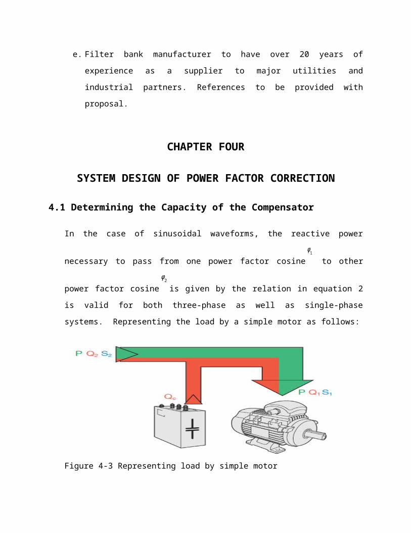
In the case of sinusoidal waveforms, the reactive power necessary to pass from one power
factor cosine
ϕ1
to other power factor cosine
ϕ2
is given by the relation in equation 2 is valid
for both three-phase as well as single-phase systems. Representing the load by a simple
motor as follows:
Figure 4-3 Representing load by simple motor

Figure 4.2 phase diagrams of power & current
)(coscos)( 1 pf
S
P
I
IpfFactorPower R
tan ϕ1=Q 1
P⇒Q 1=P tan ϕ1 , tan ϕ2=
Q 2
P⇒Q 2=P tan ϕ2 ,
Q 2=Q1 −QC , ⇒Q C=Q 1− Q2 =P tan ϕ1−P tan ϕ2
Q C=P [ tan ϕ1− tan ϕ2 ]=P [ tan( cos−1 ( pf 1 ))−tan (cos−1 ( pf 2 ))] (2)
Where:
P is the active power
Q 1 , ϕ1
are the reactive power and the phase displacement angle before power factor
correction
Q 2 , ϕ2
are the reactive power and the phase displacement angle after power factor correction
Q C
is the reactive power for power factor correction
4.2 Technical Advantage of Power Factor Correction
As previously mentioned, by correcting the power factor of an installation supplying locally the
necessary reactive power, at the same level of required output power, it is possible to reduce the
current value and consequently the total power absorbed on the load side; this implies numerous
advantages, among which a better utilization of electrical machines (generators and transformers)
and of electrical lines (transmission and distribution lines). In the case of sinusoidal waveforms,
the reactive power necessary to pass from one power factor cosine
ϕ 1
to a power factor cosine
ϕ 2
is given by in equation (2) (valid for both three-phase as well as single-phase systems).

4.2.1 Better utilization of electrical machines (transformers)
Generators and transformers are sized according to the apparent power S. At the same active
power P, the smaller the reactive power Q to be delivered, the smaller the apparent power. Thus,
by improving the power factor of the installation, these machines can be sized for a lower
apparent power, but still deliver the same active power.
Table 4-2 Rating of transformers at different power factor
Power of the Transformer in KW at different PF (cosineϕ )
KVA 0.5 0.6 0.7 0.8 0.9 0.95 1
63 32 38 44 50 57 63
100 50 60 70 80 90 100
125 63 75 88 100 113 125
160 80 96 112 128 144 160
200 100 120 140 160 180 200
250 125 150 175 200 225 250
315 158 189 221 252 284 315
400 200 240 280 320 360 400
630 315 378 441 504 567 630
800 400 480 560 640 720 800
1000 500 600 700 800 900 1000
1250 625 750 875 1000 1125 1250
4.2.2. Better utilization of electrical lines
Power factor correction allows obtaining advantages also for cable sizing. In fact, as previously
said, at the same output power, by increasing the power factor the current diminishes. This
reduction in current can be such as to allow the choice of conductors with lower cross sectional
area.

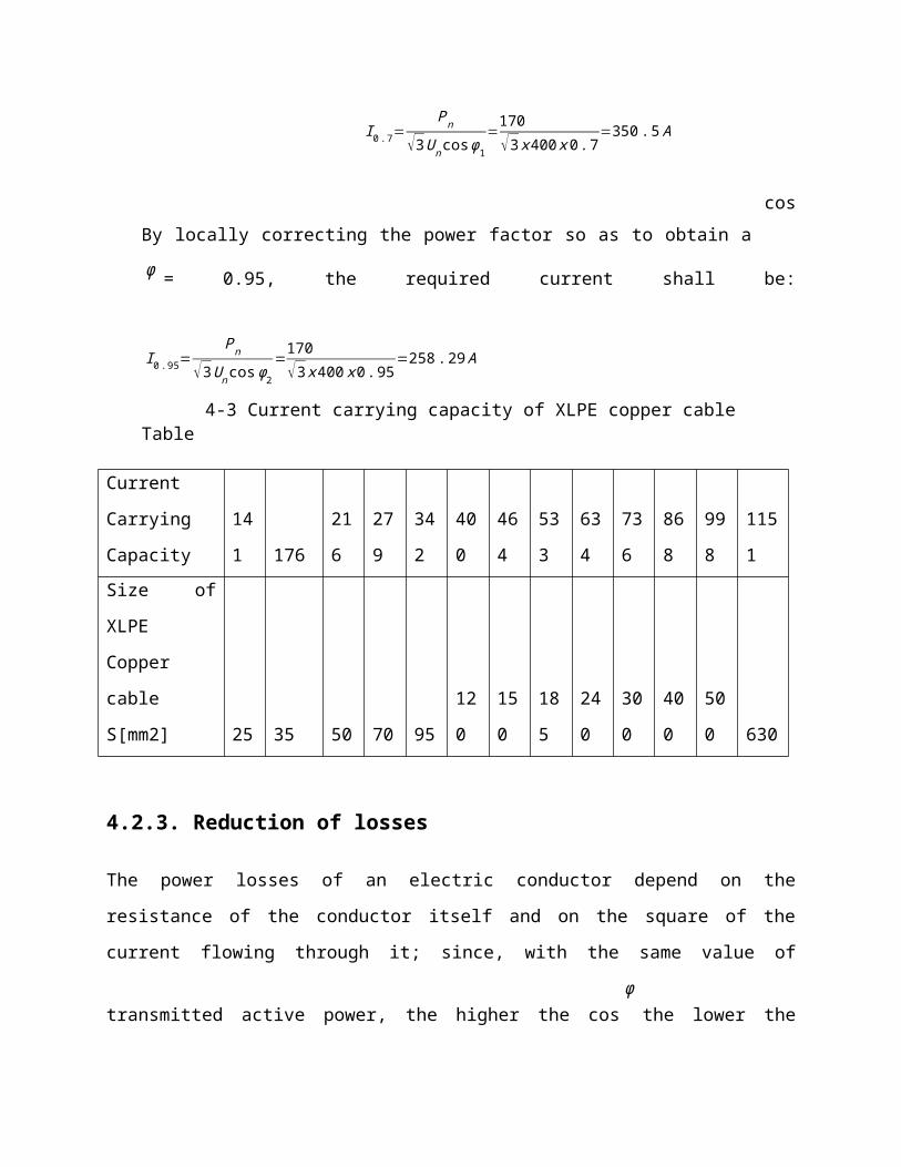
To make it clear through a practical example, take into consideration a load requiring a power Pn
equal to 170 kW with cosϕ = 0.7, at a voltage Un= 400 V; the absorbed current I 0 . 7 is:
I 0.7=P n
√3U ncosϕ1
=170√3 x400 x 0 .7
=350. 5 A
By locally correcting the power factor so as to obtain a
cosϕ = 0.95, the required current
shall be:
I 0.95=P n
√3Uncos ϕ2
=170√3 x 400 x0 .95
=258 . 29 A
Table 4-3 Current carrying capacity of XLPE copper cable
Current
Carrying
Capacity
14
1 176
21
6
27
9
34
2
40
0
46
4
53
3
63
4
73
6
86
8
99
8
115
1
Size of XLPE
Copper cable
S[mm2] 25 35 50 70 95
12
0
15
0
18
5
24
0
30
0
40
0
50
0 630
4.2.3. Reduction of losses
The power losses of an electric conductor depend on the resistance of the conductor itself and on
the square of the current flowing through it; since, with the same value of transmitted active
power, the higher the cos
ϕthe lower the current, it follows that when the power factor rises, the
losses in the conductor on the supply side of the point where the power factor correction has
been carried out will decrease.
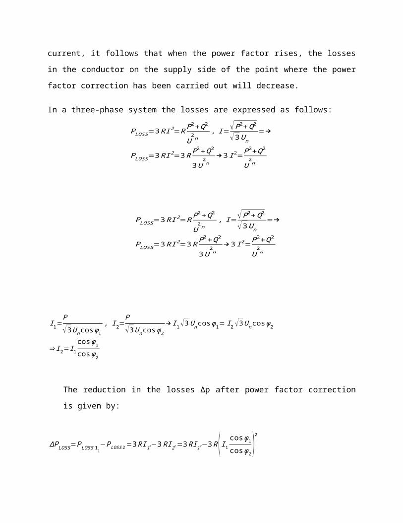
In a three-phase system the losses are expressed as follows:

PLOSS=3RI 2=RP2+Q2
U2n
, I=√P2+Q2
√3Un
=→
PLOSS=3RI 2=3RP2+Q2
3U2n
→3 I 2=P2+Q2
U2n
PLOSS=3RI 2=RP2+Q2
U2n
, I=√P2+Q2
√3Un
=→
PLOSS=3RI 2=3RP2+Q2
3U2n
→3 I 2=P2+Q2
U2n
I 1=P
√3Un cosϕ1
, I 2=P
√3U ncos ϕ2
→I 1√3Uncos ϕ1= I 2 √3Uncos ϕ2
⇒ I 2=I 1
cosϕ1
cosϕ2
The reduction in the losses Δp after power factor correction is given by:
ΔP LOSS=PLOSS 11−PLOSS 2=3 RI 12−3 RI 22=3RI 12−3R (I 1
cosϕ1
cosϕ2)
2
ΔP LOSS=PLOSS 11[1−(cosϕ1
cos ϕ2)
2] (3)
4.2.4. Reduction of voltage drop
At the same level of transmitted active power, the voltage drop shall be the smaller, the higher
the power factor. As it can be noticed in the following figures showing the diagrams of the phase
voltage drop ΔV, the smaller the phase displacement angle
ϕbetween voltage and current (with
the same active component of the load current and therefore with the same active power) the
smaller the voltage variation; moreover, this variation is minimum if there is no reactive power
absorption (current in phase).
The voltage drop in a line to line voltage of three phase line expressed as:-
ΔU=√3 . I .(R cosϕ+X sinϕ )
(4)
Excessive voltage drops can make your motors sluggish, and cause them to overheat. Low
voltage also interferes with lighting, the proper application of motor controls and electrical and
electronic instruments. Capacitors will raise your plant voltage level, and keep it up along your
feeders, right out to the last motors. Motor performance is improved and so is production. An
estimate of voltage rise from the installation of power capacitors to a factory electrical system
can be made. [2]
% voltage rise=KVar of capacitor*% impedance of TransformerKVA of Transformer
(5)
4.3. Economic advantages of power factor correction
Power supply authorities apply a tariff system which imposes penalties on the drawing of energy
with a monthly average power factor lower than 0.9. The contracts applied are different from
country to country and can vary also according to the type of costumer: as a consequence, the
following remarks are to be considered as a mere didactic and indicative information aimed at
showing the economic saving which can be obtained thanks to the power factor correction.
Generally speaking, the power supply contractual clauses require the payment of the absorbed
reactive energy when the power factor is included below 0.9, whereas nothing is due if it is
higher than 0.9.

For cosϕ < 0.7 power supply authorities can oblige consumers to carry out power factor
correction. (Put EEPCo standard here)
It is to be noted that having a monthly average power factor higher than or equal to 0.9 means
requesting from the network a reactive energy lower than or equal to 50% of the active energy:
tan ϕ=QP⊆0 .5→cosϕ⊇ 0. 89
Therefore no penalties are applied if the requirements for reactive energy do not exceed 50% of
the active one. The cost that the consumer bears on a yearly base when drawing a reactive energy
exceeding that corresponding to a power factor equal to 0.9 can be expressed by the following
relation:
PF penalty=Latest max demand∗KW cons tan t∗PF difference∗penalty factor in birrKW constant=CT ratio*assignment of the meter property (1div=xx watt)
E.g 1div=30w, 360w…
Difference of power factor=desired power factor-actual power factor
Penalty factor in birr (current EEPCo penalty factor is 68.369 for lv & 61.634 birr for mv)). If
the power factor is corrected at 0.9 not to pay the consumption of reactive energy, the cost of the
capacitor bank and of the relevant installation will be:
CQC=QC .CC
(6)
Where:
CQC is the yearly cost in birr to get a power factor equal to 0.9;
QC is the power of the capacitor bank necessary to have a cosϕ of 0.9, in kvar;
CC is the yearly installation cost of the capacitor bank in birr/kvar.
The saving for the consumer shall be:
CEQ−CQC=(EQ−0 .5 EP ) .C−CQCC
(7)
Where CEQ is the sum of 12 month power factor penalty
It is necessary to note that the capacitor bank represents an “installation cost” to be divided
suitably for the years of life of the installation itself applying one or more economic coefficients;

in the practice, the savings obtained by correcting the power factor allow the payback of the
installation cost of the capacitor bank within the first years of use. If an automatically-controlled
capacitor bank for power factor correction with Qc=xkvar, against a total installation cost per
year Cc of x birr/kvar, a total cost of xx birr is obtained. The saving for the consumer, without
keeping into account the payback and the financial charges, shall be in equation (7):
4.4. Types of power factor correction
In the previous topics the technical and economic advantages of power factor correction have
been discussed. Now it is important to understand where the capacitors are to be installed for a
better exploitation of such advantages. There are no general rules applicable to every type of
installation and, in theory, capacitors can be installed at any point, but it is necessary to evaluate
the relevant practical and economical feasibility. According to the location modalities of the
capacitors, the main methods of power factor correction are:
distributed power factor correction;
group power factor correction;
centralized power factor correction;
combined power factor correction;
Automatic power factor correction.
4.4.1. Distributed power factor correction
Distributed power factor correction is achieved by connecting a capacitor bank properly sized
directly to the terminals of the load which demands reactive power. The installation is simple and
inexpensive; capacitor and load can use the same protective devices against over currents and are
connected and disconnected simultaneously. This type of power factor correction is advisable in
the case of large electrical equipment with constant load and power and long connection times
and it is generally used for motors and fluorescent lamps.
Figure 2.3 shows the common connection diagrams for the power factor correction of motors. In
case of direct connection (diagrams 1 and 2), the following risk may be run: after the
disconnection from the supply, the motor will continue to rotate (residual kinetic energy) and
self-excite with the reactive energy drawn from the capacitor bank, and may turn into an
asynchronous generator. In this case, the voltage on the load side of the switching and control
device is maintained, with the risk of dangerous over voltages (up to twice the rated voltage
value). When using diagram 3, the compensation bank is connected only after the motor has been
started and disconnected in advance with respect to the switching off of the motor supply. With
this type of power factor correction the network on the supply side of the load works with a high
power factor.
Figure 4-4 common connection diagrams for the power factor correction

ADVANTAGES:
Can be switched on or off with the motors, eliminating the need for separate switching devices or
over current protection. Also, only energized when the motor is running, since kVAR is located
where it is required, line losses and voltage drops are minimized; while system capacity is
maximized.
4.4.2 Group power factor correction
It consists in improving locally the power factor of groups of loads having similar functioning
characteristics by installing a dedicated capacitor bank. This is the method reaching a
compromise between the inexpensive solution and the proper management of the installation
since the benefits deriving from power factor correction shall be felt only by the line upstream
the point where the capacitor bank is located.
Figure 4-5 Group power factor corrections
4.4.3 Centralized power factor correction
The profile of loads connected during the day has a primary importance for the choice of the
most convenient type of power factor correction. For installations with many loads, where not all
the loads function simultaneously and/or some loads are connected for just a few hours a day, it
is evident that the solution of distributed power factor correction becomes too onerous since
many of the installed capacitors stay idle for a long time. Therefore the use of one compensation
system only located at the origin of the installation allows a remarkable reduction of the total
power of the installed capacitors.
Figure 4-6 centralized power factor corrections
In centralized power factor correction automatic assemblies are normally used (see below
automatic power factor correction) with banks divided into steps, installed directly in the main
distribution boards; the use of a permanently connected bank is possible only if the absorption of
reactive energy is quite constant all day long. The centralized solution allows an optimization of
the costs of the capacitor bank, but presents the disadvantage that the distribution lines on the
load side of the power factor correction device shall be sized keeping into account the full
reactive power absorbed by the loads.
4.4.4. Combined power factor correction
This solution derives from a compromise between the two solutions of distributed and
centralized power factor correction and it exploits the advantages they offer. In such way, the
distributed compensation is used for high power electrical equipment and the centralized
modality for the remaining part. Combined power factor correction is prevailingly used in
installations where large equipment only are frequently used; in such circumstances their power

factor is corrected individually, whereas the power factor of small equipment is corrected by the
centralized modality.
4.5 Automatic power factor correction
In most installations there is not a constant absorption of reactive power for example due to
working cycles for which machines with different electrical characteristics are used. In such
installations there are systems for automatic power factor correction which, thanks to a
monitoring varmetric device and a power factor regulator, allow the automatic switching of
different capacitor banks, thus following the variations of the absorbed reactive power and
keeping constant the power factor of the installation constant.
An automatic compensation system is formed by:
some sensors detecting current and voltage signals;
an intelligent unit which compares the measured power factor with the desired one and
operates the connection and disconnection of the capacitor banks with the necessary
reactive power (power factor regulator);
an electric power board comprising switching and protection devices;
Some capacitor banks.
To supply a power as near as possible to the demanded one, the connection of the capacitors is
implemented step by step with a control accuracy which will be the greater the more steps are
foreseen and the smaller the difference is between them.
Benefits of Automatic Power Factor Correction
Consistently high power factor under fluctuating loads
Prevention of leading power factor
Eliminate power factor penalty
Lower energy consumption by reducing losses.
Continuously sense and monitor load
Automatically switch on/off relevant capacitors steps for consistent power factor.
Ensures easy user interface
Protect under any internal fault

Working principle of Automatic Power Factor Correction (APFC):
Suitable switching devices with coupled with inrush current limiting devices are
provided for each step
Power Factor sensed by CT in line side
kVAr required to achieve target PF is computed by the Microprocessor based APFC
relay
APFC relay switches appropriate capacitor steps
CT senses improved PF and gives feedback
Thus target PF is achieved
Wiring diagram of APFC system
Figure 4-7 Wiring diagram of APFC system
4.6 Choice of switching and protection device

A system for power factor correction is constituted essentially by:
a protective device;
a switching device (contactor);
one or more capacitors suitably connected;
Resistors for capacitor discharge.
In case of an automatic compensation system, also a control station unit to command switching
on/off of the capacitors.
4.6.1 Choice of the protective device
The devices used for the protection of capacitor banks shall satisfy the following requirements
and therefore shall:
1. Sustain the transient current which occurs when connecting and disconnecting the
capacitor banks. In particular, the instantaneous protections of the thermal magnetic and
electronic trip units shall not trip due to inrush currents;
2. sustain the periodic or permanent over currents due to the voltage harmonics and to the
tolerance on the rated capacitance value;
3. Be coordinated with any external switching device (contactors).
Furthermore, the making and breaking capacity of the circuit-breaker shall be suitable to the
short-circuit level of the installation.
The Standards IEC 60831-1 and IEC 60931-1 prescribe that:
capacitors shall be able to operate under steady-state conditions with an r.m.s. current
value up to 30% higher than their rated current Icn (this is due to the possible presence of
voltage harmonics in the network);
a tolerance of +10% on the capacitance for banks up to 100 kvar and of 5% for banks
exceeding 100 kvar is admitted (Amendment 1 of the above mentioned standards).
Therefore, a capacitor bank can absorb a maximum current Icmax of:
QC⊆100K var→ IC max=1. 3 x1 .1 xQC
√3.Un
=1. 43 ICn
QC⊇100K var→ IC max=1.3 x1 .05xQC
√3 .U n
=1 .365 ICn
Where:
Qc is the reactive power;
Un is the rated line-to-line voltage;
Icn is the rated current.
To summarize, depending on the rated reactive power of the capacitor bank, to guarantee a
correct protection against overload:
the rated current of the circuit-breaker shall be higher than the above mentioned values;
The setting of the overload protection shall be equal to the given values.
The connection of a capacitor bank, comparable to a making operation under short-circuit
condition, is associated with transient currents, at high frequency (1 to 15 kHz), of short duration
(1 to 3 ms), with high peak (25 to 200x.Icn).
For the protection of the capacitor bank:
the circuit-breaker shall have an adequate making capacity;
The setting of the instantaneous protection against short-circuit shall not cause unwanted
tripping.
The second condition is usually respected:
for thermal magnetic trip units, by setting the magnetic protection IT at values not lower
than 10.Icmax IT⊇10 xICmax
For electronic trip units, by setting in OFF the instantaneous protection against short
circuit (IT = OFF).
4.6.2 Choice of the switching device (contactor)
Capacitors or capacitors banks are usually switched by a contactor which shall be chosen so that
it can operate properly; more precisely, the contactor shall be sized so that:
it can sustain a current equal to the Icmax of the capacitor bank;
It can sustain without damages the inrush current of the capacitors.
Furthermore the contactor must be protected against short-circuit by the protection device.
4.7 Choice of the capacitor
The capacitor supplies the reactive power necessary to increase the power factor up to the
desired value. The characteristics of a capacitor, reported on its nameplate, are:
rated voltage Un;
rated frequency f;
Reactive power Qc, expressed in kvar (reactive power of the capacitor bank).
It is necessary to note that the reactive power at the service voltage is different from the rated
power given on the nameplate and referred to the rated voltage; the following formula allows to
calculate the effective power of a capacitor or of a capacitor bank:
Qsup plied=⊆QC (U e
U n)2
Where: Qc is the reactive power at the rated voltage Un;
Qsupplied is the effective power at the service voltage Ue.
Three phase circuit
In a three-phase circuit, the capacitors can be star or delta connected. The following table shows
the values of power and rated current according to the connection modality.
Figure 4-7 capacitors in star- or delta-connected
4.8. Discharge of capacitors
When installing a capacitor it is necessary to verify that at the moment when it is switched off it
can discharge so that the presence, at it terminals, of a voltage dangerous for people and things
can be avoided. In compliance with the Standard IEC 60252-2 for the power factor correction of

motors discharge devices are not often required, in particular when the capacitors are
permanently connected to the terminals of the motor windings functioning as discharge
resistances. When a discharge device is provided, it shall reduce the voltage at the capacitor
terminals from the peak value of the rated voltage to a value of 50 V or less in the time of 1 min
from the moment the capacitor is switched off. A discharge device may sometimes be specified,
not for safety reasons, but to prevent electrical overstress on the capacitor: this may occur when a
disconnected capacitor still charged is reconnected across another capacitor of different polarity.
The Std. IEC 60364-5-55, clause 559.8) prescribes the use of discharge resistors for
compensation capacitors having a total capacitance exceeding 0.5 μF (75/25 kvar with star/delta
connection at 400 V). Resistors have the purpose of nullifying, within a short time, the residual
charge on the plates of the capacitor once it has been disconnected from the network. It is a good
rule to provide discharge resistances for all the capacitors with power exceeding 0.5 kvar, for
whatever supply voltage.
In compliance with the Std. IEC 60831-1 clause 22 ‘Each capacitor unit and/or bank shall be
provided with a means for discharging each unit in 3 min to 75 V or less, from an initial peak
voltage of times rated voltage Un.’ Attention is drawn to the fact that in some countries smaller
discharge times and voltages are required. The discharge resistance in a single-phase unit or in a
phase of a polyphase unit is given by:
R⊆ t
KxCx ln(√2Un
Ur )Where:
R is the discharge resistance in [ohm];
t is the discharge time from Un to Ur, in [s];
Un is the rated voltage in [V];
Ur is the admitted residual voltage in [V];
k is a coefficient depending on the connection modality of resistors to
capacitor units, see in the following table;
C is the capacitance of the capacitor bank [F].

Figure 4.8 Discharge of capacitors

CHAPTER FIVE
CONCLUSION AND RECOMMANDETION