Embed Size (px)
Citation preview
esd Protocol for CAN Modules Rev. 3.2
esd Protocolfor
CAN Modules

esd Protocol for CAN Modules Rev. 3.2
N O T E
The information in this document has been carefully checked and is believed to be entirely reliable. esdmakes no warranty of any kind with regard to the material in this document, and assumes noresponsibility for any errors that may appear in this document. esd reserves the right to make changeswithout notice to this, or any of its products, to improve reliability, performance or design.
esd assumes no responsibility for the use of any circuitry other than circuitry which is part of a productof esd gmbh.
esd does not convey to the purchaser of the product described herein any license under the patent rightsof esd gmbh nor the rights of others.
esd electronic system design gmbhVahrenwalder Str. 205D-30165 HannoverGermany
Phone: +49-511-372-980FAX: +49-511-633-650Email: [email protected]: http://www.esd-electronics.com
This document shall not be duplicated, nor its contents used for any purpose, unless express permission has been granted.
Copyright by esd
esd Protocol for CAN Modules Rev. 3.2
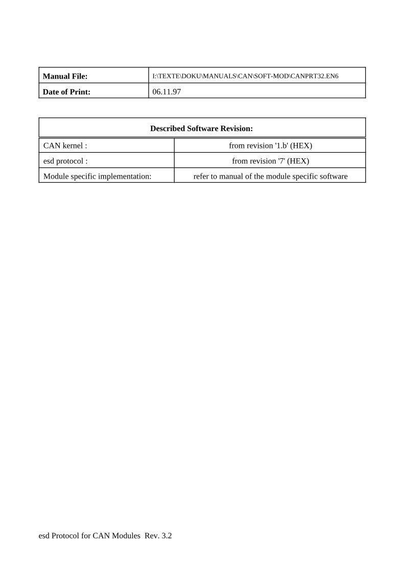
Manual File: I:\TEXTE\DOKU\MANUALS\CAN\SOFT-MOD\CANPRT32.EN6
Date of Print: 06.11.97
Described Software Revision:
CAN kernel : from revision '1.b' (HEX)
esd protocol : from revision '7' (HEX)
Module specific implementation: refer to manual of the module specific software

esd Protocol for CAN Modules Rev. 3.2
Changes in the chapters
The changes in the user's manual listed below affect changes in the firmware, as well as changes thedescription of the facts only.
Chapter Changes versus revision
Further technical changes are subject to change without notice.
esd Protocol for CAN Modules Rev. 3.2 i - 1
Content Page
1. Introduction . . . . . . . . . . . . . . . . . . . . . . . . . . . . . . . . . . . . . . . . . . . . . . . . . . . . . . . . . . . . . . 1 - 11.1 Notes to this Manual . . . . . . . . . . . . . . . . . . . . . . . . . . . . . . . . . . . . . . . . . . . . . . . . . 1 - 11.2 Specification of the esd Protocol . . . . . . . . . . . . . . . . . . . . . . . . . . . . . . . . . . . . . . . . 1 - 11.3 General Notes on Data Transmission . . . . . . . . . . . . . . . . . . . . . . . . . . . . . . . . . . . . . 1 - 11.4 General Hardware Functions . . . . . . . . . . . . . . . . . . . . . . . . . . . . . . . . . . . . . . . . . . 1 - 21.5 Parameters after a RESET . . . . . . . . . . . . . . . . . . . . . . . . . . . . . . . . . . . . . . . . . . . . . 1 - 21.6 Calling the Commands and Setting the Parameters . . . . . . . . . . . . . . . . . . . . . . . . . 1 - 6
2. Overview of the Implemented Commands and Parameters . . . . . . . . . . . . . . . . . . . . . . . 2 - 12.1 Overview of the Commands . . . . . . . . . . . . . . . . . . . . . . . . . . . . . . . . . . . . . . . . . . . 2 - 12.2 Overview of the Returned Parameter Values . . . . . . . . . . . . . . . . . . . . . . . . . . . . . . . 2 - 5
3. Description of the Individual Commands and Parameters . . . . . . . . . . . . . . . . . . . . . . . . 3 - 13.1 Configuration Reply . . . . . . . . . . . . . . . . . . . . . . . . . . . . . . . . . . . . . . . . . . . . . . . . . . 3 - 13.2 System Parameters . . . . . . . . . . . . . . . . . . . . . . . . . . . . . . . . . . . . . . . . . . . . . . . . . . . 3 - 73.3 Process TxIds . . . . . . . . . . . . . . . . . . . . . . . . . . . . . . . . . . . . . . . . . . . . . . . . . . . . . . 3 - 203.4 Process RxIds . . . . . . . . . . . . . . . . . . . . . . . . . . . . . . . . . . . . . . . . . . . . . . . . . . . . . . 3 - 233.5 Cyclic Tx Transfers (Tx Activate Time) . . . . . . . . . . . . . . . . . . . . . . . . . . . . . . . . . 3 - 263.6 Process Module Memory . . . . . . . . . . . . . . . . . . . . . . . . . . . . . . . . . . . . . . . . . . . . . 3 - 29
3.6.1 Internal RAM and XRAM, EEPROM . . . . . . . . . . . . . . . . . . . . . . . . . . . 3 - 293.6.2 External Memory . . . . . . . . . . . . . . . . . . . . . . . . . . . . . . . . . . . . . . . . . . . 3 - 333.6.3 Extended Memory . . . . . . . . . . . . . . . . . . . . . . . . . . . . . . . . . . . . . . . . . . . 3 - 353.6.4 Program Code . . . . . . . . . . . . . . . . . . . . . . . . . . . . . . . . . . . . . . . . . . . . . . 3 - 38
3.7 Process User Parameters . . . . . . . . . . . . . . . . . . . . . . . . . . . . . . . . . . . . . . . . . . . . . 3 - 403.8 Process Rx Mode . . . . . . . . . . . . . . . . . . . . . . . . . . . . . . . . . . . . . . . . . . . . . . . . . . . 3 - 423.9 Allocation of Pin Names . . . . . . . . . . . . . . . . . . . . . . . . . . . . . . . . . . . . . . . . . . . . . 3 - 463.10 Service Request . . . . . . . . . . . . . . . . . . . . . . . . . . . . . . . . . . . . . . . . . . . . . . . . . . . 3 - 493.11 Setting the Absolute Module-Time and Synchronisation of the Modules . . . . . . . 3 - 513.12 Supervisor Commands . . . . . . . . . . . . . . . . . . . . . . . . . . . . . . . . . . . . . . . . . . . . . . 3 - 53
4. Examples for Parameterization . . . . . . . . . . . . . . . . . . . . . . . . . . . . . . . . . . . . . . . . . . . . . . 4 - 14.1 Setting the Tx Identifier TxId1 . . . . . . . . . . . . . . . . . . . . . . . . . . . . . . . . . . . . . . . . . 4 - 14.2 Restoring the Default Parameters . . . . . . . . . . . . . . . . . . . . . . . . . . . . . . . . . . . . . . . 4 - 3
4.2.1 ...if the actual module no. is unknown . . . . . . . . . . . . . . . . . . . . . . . . . . . . 4 - 34.2.2 ...if the module no. is known . . . . . . . . . . . . . . . . . . . . . . . . . . . . . . . . . . . . 4 - 4

esd Protocol for CAN Modules Rev. 3.2i - 2
Overview
esd Protocol for CAN Modules Rev. 3.2 1 - 1
1. Introduction
1.1 Notes to this Manual
This manual describes the 'esd-CAN protocol' for esd-CAN modules. By this protocol it is possible toset the CAN parameters of the modules, as for example, the Rx and Tx identifiers or the baudrate.Apart from the CAN parameters it is also possible to set and play back module-specific parameters(user parameters) with the help of the protocol.
In the chapter 'Overview of the implemented commands and parameters' all commands supported at themoment are shown in a tabular summary.
Depending on the respective module type restrictions of the functions might possibly occur. Notes onthis can be found in the description of the module-specific software. There the individual userparameters of the used module are described in detail, too.
1.2 Specification of the esd Protocol
On the basis of its problem-oriented structure the esd protocol cannot be categorized clearly into a layerof the ISO layer model: It offers services which range from fundamental functions, as e.g., the inquiryof the status of the CAN hardware controller up to application-specific adjustments, as, e.g., the settingof so-called 'user parameters'.
The esd protocol offers functions which are comparable, e.g., with the LMT (layer management) in theCAL (CAN application layer). Because the identifier allocation occurs by the esd protocol, too, itsfunctionalities are partly similar to those of the DBT (identifier distributor) in the CAL, as well.
But the esd protocol is operated totally independently and has got no interface to the CAL!
1.3 General Notes on Data Transmission
In the following descriptions the transmission direction of data is looked at, if not other wisely stated,from the module. The module receives data on the 'Rx identifier' and transmits data on the 'Txidentifier'.
The data bytes are counted from 1 to 8 and are always transmitted in the order byte 1...byte 8. Thenumber of transmitted bytes can vary from 0 to 8. The data transmission has to start with byte 1 andprogress in continuous order (e.g., byte 1, byte 2, byte 3 - not possible, e.g., byte 1, byte 7, byte 8).
Generally only those bytes are overwritten which are received by the module. The data of not recordedbytes remain unchanged.
Overview
esd Protocol for CAN Modules Rev. 3.21 - 2
1.4 General Hardware Functions
To use the esd CAN protocol at the CAN modules at each module the following hardware circuits arenecessary:
CAN controller 8xC592 (or compatible)The controller has a internal RAM, that is used as a working memory. In this RAM thedynamical parameters are stored. The RAM ist deleted with each RESET.
I²C EEPROMThe I²C EEPROM is used for storing the configuration parameters. The data will remain storedin power off condition or after a RESET.
Coding switchVia the coding switch, e.g. the default value of the module no. is set.
Further descriptions can be read in the hardware manual of the module.
1.5 Parameters after a RESET
The module offers various possibilities to trigger a RESET:
A power-on RESET, a RESET by the EMERGENCY-STOP inputs and a RESET by the generalcommand 'RESET module' reset the local components.Furthermore the module is able to trigger a RESET independently when the hardware watchdog hasexpired. This RESET also resets the local components without changing the stored parameters.
The listed RESETs only change the parameters of the module filed in the I²C EEPROM, if theconditions apply which are listed in the table below.
The module also supports the command 'default RESET'. By this command a local RESET is triggeredand the parameters of the module are always overwritten with the default parameters.
The used parameters with which the module operates after a power-on RESET, a RESET by theEMERGENCY STOP inputs or a RESET by the general command 'RESET module', depend mainlyon three factors:
The switch position of the coding switches, the availability of the I²C EEPROM data and the modulenumber (parameter 'module no.') stored in the I²C EEPROM.
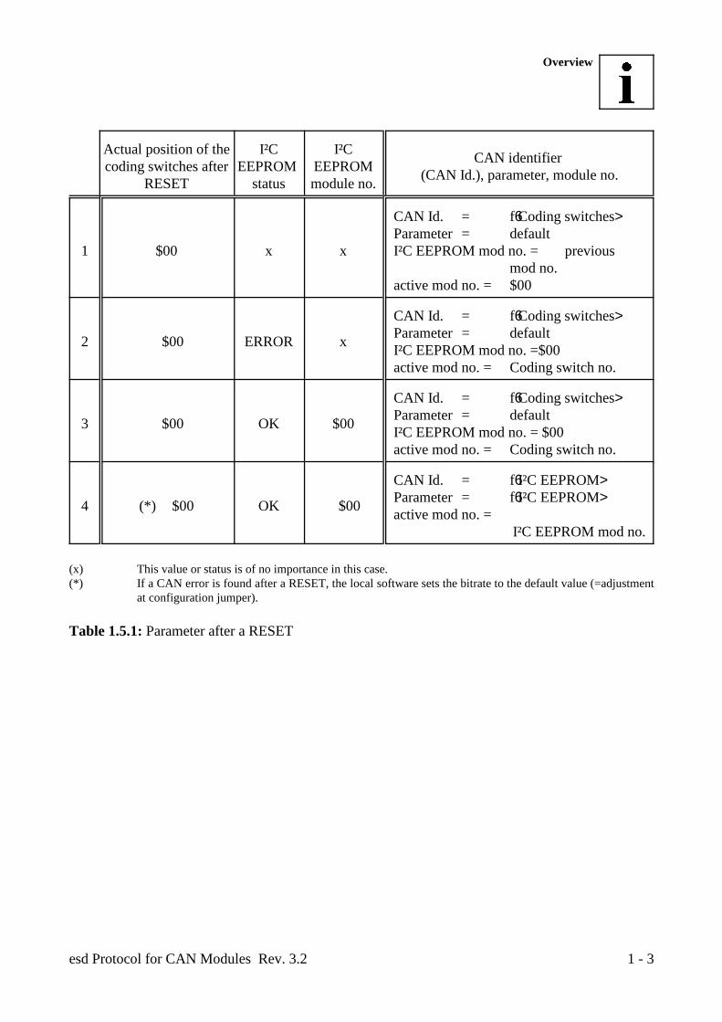
The following table should give an overview of the resulting parameters. It does not contain the 'defaultRESET', because this does always lead to the activation of the default parameters.
Overview
esd Protocol for CAN Modules Rev. 3.2 1 - 3
Actual position of the I²C I²Ccoding switches after EEPROM EEPROM
RESET status module no.
CAN identifier (CAN Id.), parameter, module no.
1 $00 x x I²C EEPROM mod no. = previous
CAN Id. = f6Coding switches>Parameter = default
mod no.active mod no. = $00
2 Ö $00 ERROR x
CAN Id. = f6Coding switches>Parameter = defaultI²C EEPROM mod no. =$00active mod no. = Coding switch no.
3 Ö $00 OK $00
CAN Id. = f6Coding switches>Parameter = defaultI²C EEPROM mod no. = $00active mod no. = Coding switch no.
4 (*) Ö $00 OK Ö $00
CAN Id. = f6I²C EEPROM>Parameter = f6I²C EEPROM>active mod no. =
I²C EEPROM mod no.
(x) This value or status is of no importance in this case.(*) If a CAN error is found after a RESET, the local software sets the bitrate to the default value (=adjustment
at configuration jumper). Table 1.5.1: Parameter after a RESET
Overview
esd Protocol for CAN Modules Rev. 3.21 - 4
Explanations to Table 1.5.1:
Some of the terms from the table above will be described in detail in following sections of this manual.For a general understanding of the table, a short explanation of the terms:
Module no. ... Serial number (1...255) which can be allocated to the module by the userindependently from the module type.
active mod no. ... The module no. with which the module is selected by the initialisation identifier(INIT Id) during the parameter interchange.
I²C EEPROM mod no. ... The module no. which was stored in the local I²C EEPROM of the module. If no
change in this number had been made after the storing, the actual mod no. isidentical with the I²C EEPROM module no..
Below the combinations of factors, shown in table 1.4.1, which are decisive for the selection of thedefault parameters will be explained:
Combination 1
If the positions of the coding switches are $00 when the module starts after a RESET, the I²CEEPROM data, previously stored, will be overwritten at the moment in which the adjustment ischanged from $00 to any other value. The firmware needs about five seconds for this. Afterwards alocal RESET is triggered by the firmware. During the RESET the message outputs are activated.
The CAN identifier corresponds to the value adjusted at the coding switches.
The module operates with the default parameters.
Combination 2
The second listed combination occurs if no I²C EEPROM is available or the I²C EEPROM data arefaulty. If this is the case, the local software would use the default parameters.
The CAN identifier corresponds to the value adjusted at the coding switches. The actual module no.corresponds to the value which is adjusted on the coding switches.
Overview
esd Protocol for CAN Modules Rev. 3.2 1 - 5
Combination 3
The third combination describes the condition of the module which occurs, e.g., if the position of thecoding switches is changed from $00 to any other value.
The I²C EEPROM module no. had been set by the local software (see combination 1) to $00. (The I²CEEPROM module no. can also be set to $00 by interchanging the parameter 'module no.')
If the status of the I²C EEPROM data are correct, the module operates with the identifier on the CAN,in this combination, which is adjusted by the coding switches. The actual module no. corresponds to the value adjusted on the coding switches.
Combination 4
In this combination of the factors listed above, the module operates after a RESET with the previouslychanged and in the I²C EEPROM stored parameters.
Requirements for this are a faultless CRC check of the I²C EEPROM data (I²C EEPROM status=OK),a coding switch position unequal $00 and a module no., stored in the I²C EEPROM, which has got avalue unequal $00.
The CAN identifier with which the module operates and all used parameters are taken from the I²CEEPROM.
The actual module no. with which the module is selected in the initialisation phase corresponds to themodule no. stored in the I²C EEPROM.
Overview
esd Protocol for CAN Modules Rev. 3.21 - 6
1.6 Calling the Commands and Setting the Parameters
If an esd-CAN module is in original condition (default condition at delivery), it operates only by theCAN identifiers on the CAN (see hardware manual) adjusted by hardware.
To report the initialisation parameters to the module nevertheless, a special CAN identifier (INIT Id)has been reserved which is the same for all esd-CAN modules.
In spite of the identifier adjusted by the coding switches, the module receives and processes every CANframe transmitted on the INIT Id.
The INIT Id determined by esd has got the value:
$700
(valid since software version V0.8, subject to alterations)
The identifier $700 is reserved for the initialisation, i.e., if this identifier should wrongly be allocatedto other functions, the transmitted data will be interpreted as initialisation parameter, nevertheless!
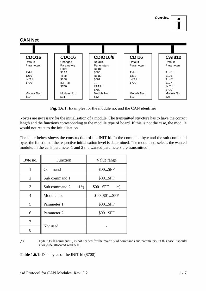
Generally not all modules should be initialized with the same parameters. To distinguish the modulesthe fourth byte of the six INIT Id bytes has to have the 'actual Module no.' of the wanted module at theinitialisation.
The module no. is a characteristic number in the area of $00...$FF which can be freely defined by theuser. It is possible, e.g., to number all existing modules (max. 255 modules), independent from thetype, continuously.
In a CAN net the same module no. should only be used once. The module no. $00 should not be used,because it is used during the initialisation sequence with global commands, which are valid for allmodules.
The actual module no. is identical with the number adjusted at the coding switches, when the moduleis operated with the default parameters.
But it is also possible to program the module no. freely during the initialisation.
RxId:$210INIT Id:$700
Module No.:$10
RxId1:$090RxId2:$091....INIT Id:$700Module No.:$12
DefaultParameters
CDO16 CDIO16/8
TxId:$313INIT Id:$700
Module No.:$13
CDI16
TxId1:$126TxId2:$127INIT Id:$700Module No.:$26
CAI812
CAN Net
RxId:$1AATxId:$258INIT Id:$700
Module No.:$11
ChangedParameters
CDO16DefaultParameters
DefaultParameters
DefaultParameters
Overview
esd Protocol for CAN Modules Rev. 3.2 1 - 7
Fig. 1.6.1: Examples for the module no. and the CAN identifier
6 bytes are necessary for the initialisation of a module. The transmitted structure has to have the correctlength and the functions corresponding to the module type of board. If this is not the case, the modulewould not react to the initialisation.
The table below shows the construction of the INIT Id. In the command byte and the sub commandbytes the function of the respective initialisation level is determined. The module no. selects the wantedmodule. In the cells parameter 1 and 2 the wanted parameters are transmitted.
Byte no. Function Value range
1 Command $00...$FF
2 Sub command 1 $00...$FF
3 Sub command 2 1*) $00...$FF 1*)
4 Module no. $00, $01...$FF
5 Parameter 1 $00...$FF
6 Parameter 2 $00...$FF
7Not used -
8
(*) Byte 3 (sub command 2) is not needed for the majority of commands and parameters. In this case it shouldalways be allocated with $00.
Table 1.6.1: Data bytes of the INIT Id ($700)
Overview
esd Protocol for CAN Modules Rev. 3.21 - 8
The parameter interchange can lead to the setting of parameters, to the reply of already adjustedparameters or to the execution of a command. At the command interchange and the setting ofparameters the highest bit of the command byte is always '1', at the request of parameters it is always'0'.
The requested reply of the module is only sent once by the module. The identifier (CTxId) which hadbeen allocated to the module for this transmission is not stored on the module. If another transmissionis desired an INIT Id with the corresponding parameters has to be transmitted to the module again.
If the module processes faultlessly and the CAN is free, it transmits the reply within 10msec.
Normally, at the reply of the actual parameter condition of the modules, in the first byte the contentsof the received command byte and in the second byte the contents of the sub command byte is given.
This is not the case if the second byte is used for the display of other parameters or an unknowncommand or sub command byte had been sent to the module. In the second case a message containingonly one byte with the contents $FF is given back to the CAN.
The given value ranges of the parameters have to be kept, because otherwise the faultlessexecution of commands is not guaranteed! No error message occurs after wrong entry of theparameter values.
Below the parameters and commands will be specified. The instructions are kept general, so that theyapply to all esd-CAN modules which have the software versions from V1.4c. The examples addedsubsequently to the specification should clarify the function course further.
The description of the bytes of the INIT Id restricts to those which are relevant for the correspondingmode.
Byte 3 (sub command 2) should, if it is not needed, always be recorded with $00. In byte 4 the actualmodule no. has to be entered, as already mentioned above.
Overview
esd Protocol for CAN Modules Rev. 3.2 2 - 1
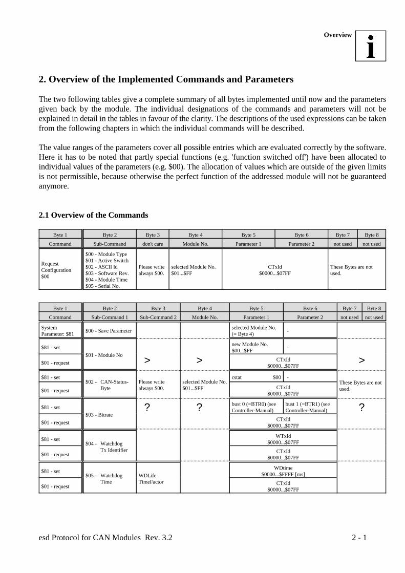
2. Overview of the Implemented Commands and Parameters
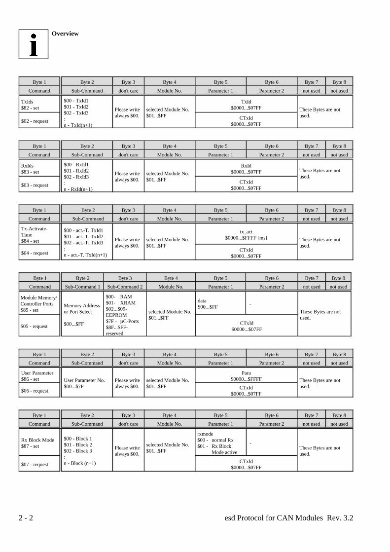
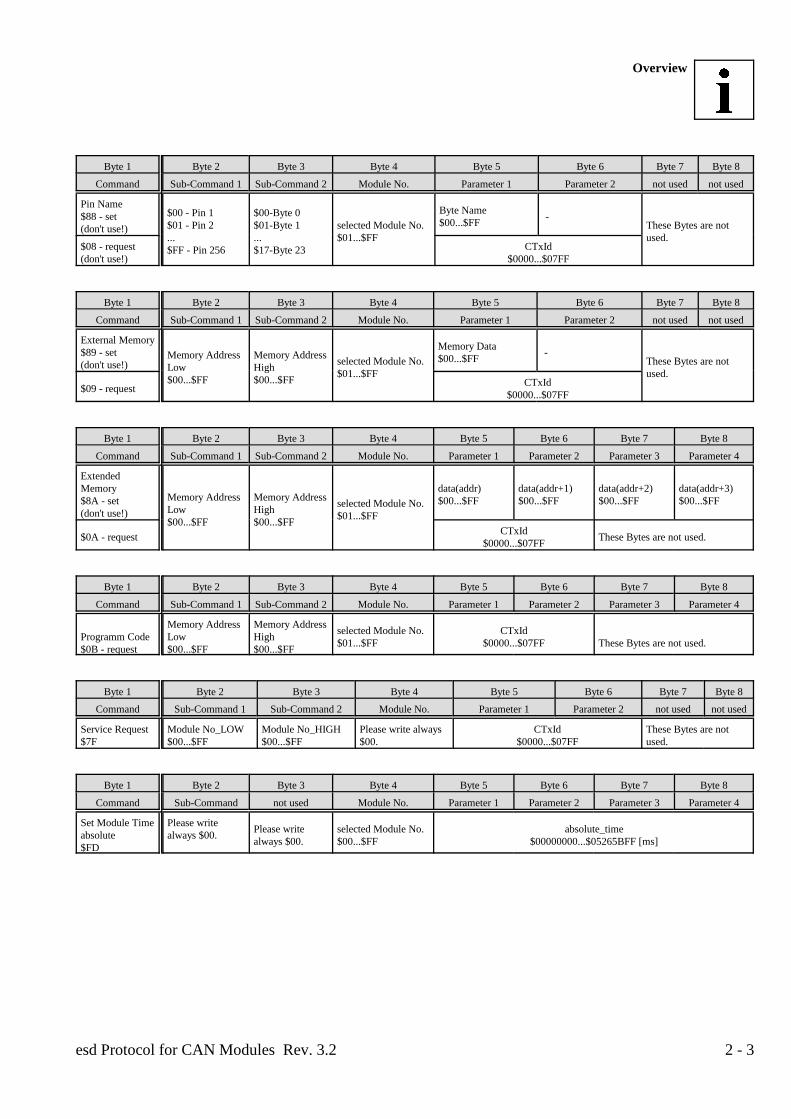
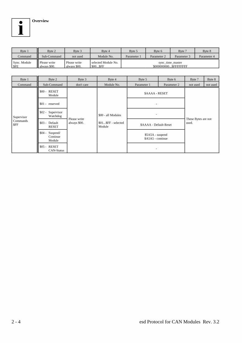
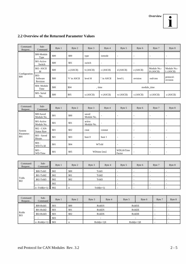
The two following tables give a complete summary of all bytes implemented until now and the parametersgiven back by the module. The individual designations of the commands and parameters will not beexplained in detail in the tables in favour of the clarity. The descriptions of the used expressions can be takenfrom the following chapters in which the individual commands will be described.
The value ranges of the parameters cover all possible entries which are evaluated correctly by the software.Here it has to be noted that partly special functions (e.g. 'function switched off') have been allocated toindividual values of the parameters (e.g. $00). The allocation of values which are outside of the given limitsis not permissible, because otherwise the perfect function of the addressed module will not be guaranteedanymore.
2.1 Overview of the Commands
Byte 1 Byte 2 Byte 3 Byte 4 Byte 5 Byte 6 Byte 7 Byte 8
Command Sub-Command don't care Module No. Parameter 1 Parameter 2 not used not used
RequestConfiguration$00
$00 - Module Type$01 - Active Switch$02 - ASCII Id Please write selected Module No. CTxId These Bytes are not$03 - Software Rev. always $00. $01...$FF $0000...$07FF used.$04 - Module Time$05 - Serial No.
Byte 1 Byte 2 Byte 3 Byte 4 Byte 5 Byte 6 Byte 7 Byte 8
Command Sub-Command 1 Sub-Command 2 Module No. Parameter 1 Parameter 2 not used not used
System selected Module No.Parameter: $81 (= Byte 4)$00 - Save Parameter -
$81 - set -$01 - Module No
> > >new Module No.$00...$FF
$01 - request CTxId$0000...$07FF
$81 - set cstat $00 - $02 - CAN-Status- Please write selected Module No.
Byte always $00. $01...$FFThese Bytes are notused.$01 - request CTxId
$0000...$07FF
$81 - set$03 - Bitrate
? ? ?bust 0 (=BTR0) (see bust 1 (=BTR1) (seeController-Manual) Controller-Manual)
$01 - request CTxId$0000...$07FF
$81 - set$04 - Watchdog
Tx Identifier
WTxId$0000...$07FF
$01 - request CTxId$0000...$07FF
$81 - set$05 - Watchdog WDLife
Time TimeFactor
WDtime$0000...$FFFF [ms]
$01 - request CTxId$0000...$07FF
Overview
esd Protocol for CAN Modules Rev. 3.22 - 2
Byte 1 Byte 2 Byte 3 Byte 4 Byte 5 Byte 6 Byte 7 Byte 8
Command Sub-Command don't care Module No. Parameter 1 Parameter 2 not used not used
TxIds TxId$82 - set $0000...$07FF
$00 - TxId1$01 - TxId2$02 - TxId3:n - TxId(n+1)
Please write selected Module No. These Bytes are notalways $00. $01...$FF used.
$02 - request CTxId$0000...$07FF
Byte 1 Byte 2 Byte 3 Byte 4 Byte 5 Byte 6 Byte 7 Byte 8
Command Sub-Command don't care Module No. Parameter 1 Parameter 2 not used not used
RxIds RxId$83 - set $0000...$07FF
$00 - RxId1$01 - RxId2$02 - RxId3:n - RxId(n+1)
Please write selected Module No.always $00. $01...$FF
These Bytes are notused.
$03 - request CTxId$0000...$07FF
Byte 1 Byte 2 Byte 3 Byte 4 Byte 5 Byte 6 Byte 7 Byte 8
Command Sub-Command don't care Module No. Parameter 1 Parameter 2 not used not used
Tx-Activate-Time$84 - set
$00 - act.-T. TxId1$01 - act.-T. TxId2$02 - act.-T. TxId3:n - act.-T. TxId(n+1)
Please write selected Module No. These Bytes are notalways $00. $01...$FF used.
tx_act$0000...$FFFF [ms]
$04 - request CTxId$0000...$07FF
Byte 1 Byte 2 Byte 3 Byte 4 Byte 5 Byte 6 Byte 7 Byte 8
Command Sub-Command 1 Sub-Command 2 Module No. Parameter 1 Parameter 2 not used not used
Module Memory/Controller Ports - $85 - set
Memory Addressor Port Select selected Module No. These Bytes are not
$00...$FF
$00- RAM$01- XRAM$02...$09-EEPROM$7F - µC-Ports$8F...$FF-reserved
$01...$FF used.
data$00...$FF
$05 - request CTxId$0000...$07FF
Byte 1 Byte 2 Byte 3 Byte 4 Byte 5 Byte 6 Byte 7 Byte 8
Command Sub-Command don't care Module No. Parameter 1 Parameter 2 not used not used
User Parameter Para$86 - set $0000...$FFFFUser Parameter No. Please write selected Module No. These Bytes are not
$00...$7F always $00. $01...$FF used.$06 - request CTxId
$0000...$07FF
Byte 1 Byte 2 Byte 3 Byte 4 Byte 5 Byte 6 Byte 7 Byte 8
Command Sub-Command don't care Module No. Parameter 1 Parameter 2 not used not used
Rx Block Mode $00 - normal Rx$87 - set $01 - Rx Block
$00 - Block 1$01 - Block 2 selected Module No.$02 - Block 3 $01...$FF:n - Block (n+1)
Please write These Bytes are notalways $00. used.
rxmode
Mode active
-
$07 - request CTxId$0000...$07FF
Overview
esd Protocol for CAN Modules Rev. 3.2 2 - 3
Byte 1 Byte 2 Byte 3 Byte 4 Byte 5 Byte 6 Byte 7 Byte 8
Command Sub-Command 1 Sub-Command 2 Module No. Parameter 1 Parameter 2 not used not used
Pin Name$88 - set - (don't use!)
$00 - Pin 1 $00-Byte 0$01 - Pin 2 $01-Byte 1 selected Module No. These Bytes are not... ... $01...$FF used.$FF - Pin 256 $17-Byte 23
Byte Name$00...$FF
$08 - request CTxId(don't use!) $0000...$07FF
Byte 1 Byte 2 Byte 3 Byte 4 Byte 5 Byte 6 Byte 7 Byte 8
Command Sub-Command 1 Sub-Command 2 Module No. Parameter 1 Parameter 2 not used not used
External Memory$89 - set - (don't use!)
Memory Address Memory AddressLow High$00...$FF $00...$FF
selected Module No. These Bytes are not$01...$FF used.
Memory Data$00...$FF
$09 - request CTxId$0000...$07FF
Byte 1 Byte 2 Byte 3 Byte 4 Byte 5 Byte 6 Byte 7 Byte 8
Command Sub-Command 1 Sub-Command 2 Module No. Parameter 1 Parameter 2 Parameter 3 Parameter 4
ExtendedMemory data(addr) data(addr+1) data(addr+2) data(addr+3)$8A - set $00...$FF $00...$FF $00...$FF $00...$FF(don't use!)
Memory Address Memory AddressLow High$00...$FF $00...$FF
selected Module No.$01...$FF
$0A - request These Bytes are not used.CTxId$0000...$07FF
Byte 1 Byte 2 Byte 3 Byte 4 Byte 5 Byte 6 Byte 7 Byte 8
Command Sub-Command 1 Sub-Command 2 Module No. Parameter 1 Parameter 2 Parameter 3 Parameter 4
Programm Code Low High$0B - request $00...$FF $00...$FF
Memory Address Memory Address selected Module No. CTxId$01...$FF $0000...$07FF These Bytes are not used.
Byte 1 Byte 2 Byte 3 Byte 4 Byte 5 Byte 6 Byte 7 Byte 8
Command Sub-Command 1 Sub-Command 2 Module No. Parameter 1 Parameter 2 not used not used
Service Request Module No_LOW Module No_HIGH Please write always CTxId These Bytes are not$7F $00...$FF $00...$FF $00. $0000...$07FF used.
Byte 1 Byte 2 Byte 3 Byte 4 Byte 5 Byte 6 Byte 7 Byte 8
Command Sub-Command not used Module No. Parameter 1 Parameter 2 Parameter 3 Parameter 4
Set Module Time Please writeabsolute always $00.$FD
Please write selected Module No. absolute_timealways $00. $00...$FF $00000000...$05265BFF [ms]
Overview
esd Protocol for CAN Modules Rev. 3.22 - 4
Byte 1 Byte 2 Byte 3 Byte 4 Byte 5 Byte 6 Byte 7 Byte 8
Command Sub-Command not used Module No. Parameter 1 Parameter 2 Parameter 3 Parameter 4
Sync. Module Please write Please write selected Module No. sync_time_master$FE always $00. always $00. $00...$FF $000000000...$FFFFFFFF
Byte 1 Byte 2 Byte 3 Byte 4 Byte 5 Byte 6 Byte 7 Byte 8
Command Sub-Command don't care Module No. Parameter 1 Parameter 2 not used not used
SupervisorCommands$FF
$00 - RESETModule
Please write These Bytes are notalways $00. $01...$FF - selected used.
$00 - all Modules
Module
$AAAA - RESET
$01 - reserved -
$02 - SupervisorWatchdog -
$03 - DefaultRESET $AAAA - Default-Reset
$04 - Suspend/ContinueModule
$5A5A - suspend$A5A5 - continue
$05 - RESETCAN-Status -
Overview
esd Protocol for CAN Modules Rev. 3.2 2 - 5
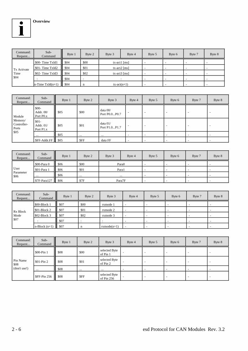
2.2 Overview of the Returned Parameter Values
Command: Sub- Request... Command Byte 1 Byte 2 Byte 3 Byte 4 Byte 5 Byte 6 Byte 7 Byte 8
Configuration$00
$00-Module Type $00 $00 type iomode - - - -
$01-Active Switch $00 $01 switch - - - - -
$02- ASCII Module No.- Module No.- Id H (ASCII) L (ASCII) $00 a (ASCII) b (ASCII) c (ASCII) d (ASCII) e (ASCII)
$03- Software $00 'V' in ASCII level H '.' in ASCII level L revision esd/cms Revision
protocol-revision
$04- Module Time $00 $04 Îtime module_time
$05- Serial No. $00 $05 u (ASCII) v (ASCII) w (ASCII) x (ASCII) y (ASCII) z (ASCII)
Command: Sub- Request... Command Byte 1 Byte 2 Byte 3 Byte 4 Byte 5 Byte 6 Byte 7 Byte 8
SystemParameter:$01
$00-Saved savedModule No. Module No. $01 $00 - - - - -
$01-Active activeModule No. Module No. $01 $01 - - - - -
$02 - CAN-Status Byte $01 $02 cstat constat - - - -
$03 - SavedBitrate $01 $03 bust 0 bust 1 - - - -
$04 - WD-Tx-Id $01 $04 WTxId - - - -
$05 - WDLifeTimeWD-Time Factor $01 $05 WDtime [ms] - - -
Command: Sub- Request... Command Byte 1 Byte 2 Byte 3 Byte 4 Byte 5 Byte 6 Byte 7 Byte 8
TxIds$02
$00-TxId1 $02 $00 TxId1 - - - -
$01-TxId2 $02 $01 TxId2 - - - -
$02-TxId3 $02 $02 TxId3 - - - -
: $02 : : - - - -
n -TxId(n+1) $02 n TxId(n+1) - - - -
Command: Sub- Request... Command Byte 1 Byte 2 Byte 3 Byte 4 Byte 5 Byte 6 Byte 7 Byte 8
RxIds$03
$00-RxId1 $03 $00 RxId1S RxId1E - -
$01-RxId2 $03 $01 RxId2S RxId2E - -
$02-RxId3 $03 $02 RxId3S RxId3E - -
: $03 : : : - -
n -RxId(n+1) $03 n RxId(n+1)S RxId(n+1)E - -
Overview
esd Protocol for CAN Modules Rev. 3.22 - 6
Command: Sub- Request... Command Byte 1 Byte 2 Byte 3 Byte 4 Byte 5 Byte 6 Byte 7 Byte 8
Tx ActivateTime $02- Time TxId3 $04 $02 tx-act3 [ms] - - - - $04
$00- Time TxId1 $04 $00 tx-act1 [ms] - - - -
$01- Time TxId2 $04 $01 tx-act2 [ms] - - - -
: $04 : : - - - -
n-Time TxId(n+1) $04 n tx-act(n+1) - - - -
Command: Sub- Request... Command Byte 1 Byte 2 Byte 3 Byte 4 Byte 5 Byte 6 Byte 7 Byte 8
ModuleMemory/Controller-Ports$05
$00-Addr. 00/ $05 $00 - - - - - Port P0.x
data 00/Port P0.0...P0.7
$01-Addr. 01/ $05 $01 - - - - - Port P1.x
data 01/Port P1.0...P1.7
... $05 ... ... - - - - -
$FF-Addr.FF $05 $FF data FF - - - - -
Command: Sub- Request... Command Byte 1 Byte 2 Byte 3 Byte 4 Byte 5 Byte 6 Byte 7 Byte 8
UserParameter$06
$00-Para 0 $06 $00 Para0 - - - -
$01-Para 1 $06 $01 Para1 - - - -
... $06 ... ... - - - -
$7F-Para127 $06 $7F Para7F - - - -
Command: Sub- Request... Command Byte 1 Byte 2 Byte 3 Byte 4 Byte 5 Byte 6 Byte 7 Byte 8
Rx BlockMode $02-Block 3 $07 $02 rxmode 3 - - - - - $07
$00-Block 1 $07 $00 rxmode 1 - - - - -
$01-Block 2 $07 $01 rxmode 2 - - - - -
: $07 : : - - - - -
n-Block (n+1) $07 n rxmode(n+1) - - - - -
Command: Sub- Request... Command Byte 1 Byte 2 Byte 3 Byte 4 Byte 5 Byte 6 Byte 7 Byte 8
Pin Name$08(don't use!)
$00-Pin 1 $08 $00 - - - - - selected Byteof Pin 1
$01-Pin 2 $08 $01 - - - - - selected Byteof Pin 2
... $08 ... ... - - - - -
$FF-Pin 256 $08 $FF - - - - - selected Byteof Pin 256
Overview
esd Protocol for CAN Modules Rev. 3.2 2 - 7
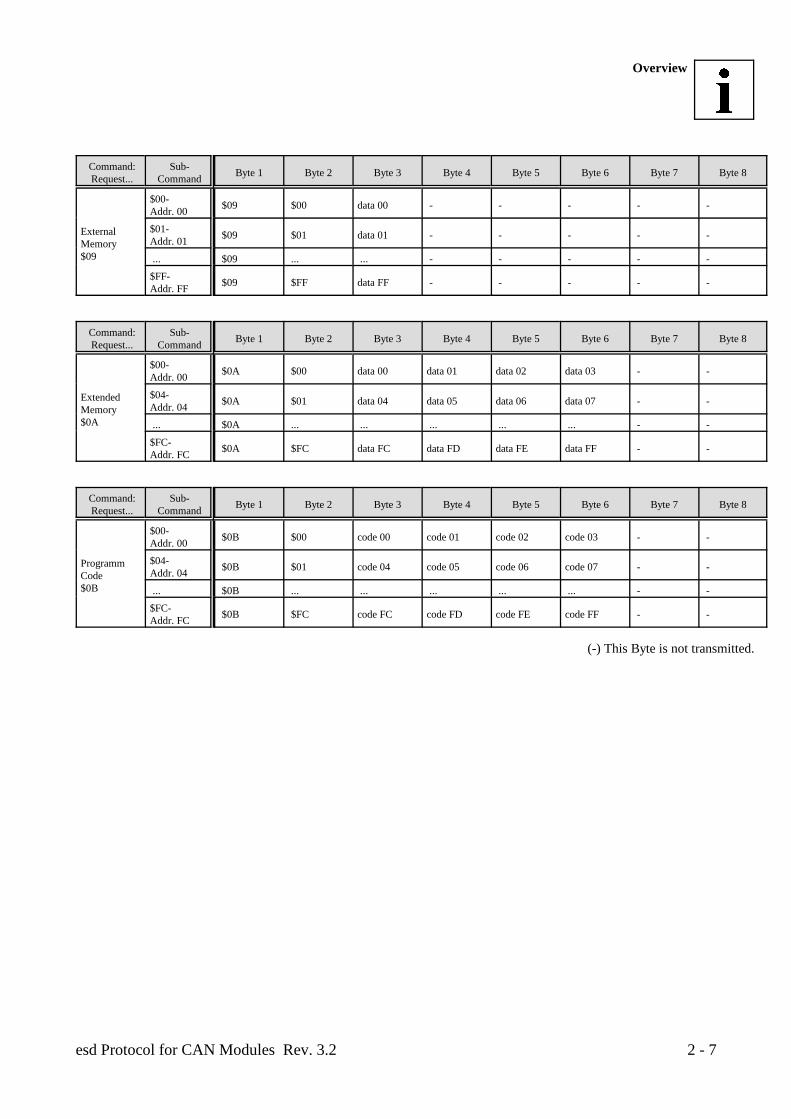
Command: Sub- Request... Command Byte 1 Byte 2 Byte 3 Byte 4 Byte 5 Byte 6 Byte 7 Byte 8
ExternalMemory$09
$00-Addr. 00 $09 $00 data 00 - - - - -
$01-Addr. 01 $09 $01 data 01 - - - - -
... $09 ... ... - - - - -
$FF-Addr. FF $09 $FF data FF - - - - -
Command: Sub- Request... Command Byte 1 Byte 2 Byte 3 Byte 4 Byte 5 Byte 6 Byte 7 Byte 8
ExtendedMemory$0A
$00-Addr. 00 $0A $00 data 00 data 01 data 02 data 03 - -
$04-Addr. 04 $0A $01 data 04 data 05 data 06 data 07 - -
... $0A ... ... ... ... ... - -
$FC-Addr. FC $0A $FC data FC data FD data FE data FF - -
Command: Sub- Request... Command Byte 1 Byte 2 Byte 3 Byte 4 Byte 5 Byte 6 Byte 7 Byte 8
ProgrammCode$0B
$00-Addr. 00 $0B $00 code 00 code 01 code 02 code 03 - -
$04-Addr. 04 $0B $01 code 04 code 05 code 06 code 07 - -
... $0B ... ... ... ... ... - -
$FC-Addr. FC $0B $FC code FC code FD code FE code FF - -
(-) This Byte is not transmitted.

esd Protocol for CAN Modules Rev. 3.22 - 8
Commands and Parameters
esd Protocol for CAN Modules Rev. 3.2 3 - 1
3. Description of the Individual Commands and Parameters
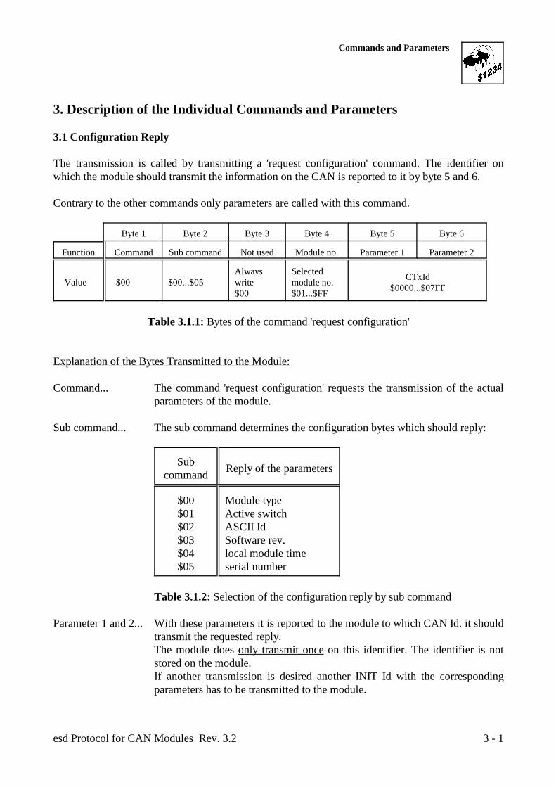
3.1 Configuration Reply
The transmission is called by transmitting a 'request configuration' command. The identifier onwhich the module should transmit the information on the CAN is reported to it by byte 5 and 6.
Contrary to the other commands only parameters are called with this command.
Byte 1 Byte 2 Byte 3 Byte 4 Byte 5 Byte 6
Function Command Sub command Not used Module no. Parameter 1 Parameter 2
Value $00 $00...$05 write module no.Always Selected
$00 $01...$FF
CTxId$0000...$07FF
Table 3.1.1: Bytes of the command 'request configuration'
Explanation of the Bytes Transmitted to the Module:
Command... The command 'request configuration' requests the transmission of the actualparameters of the module.
Sub command... The sub command determines the configuration bytes which should reply:
Subcommand Reply of the parameters
$00 Module type$01 Active switch$02 ASCII Id$03 Software rev.$04 local module time$05 serial number
Table 3.1.2: Selection of the configuration reply by sub command
Parameter 1 and 2... With these parameters it is reported to the module to which CAN Id. it shouldtransmit the requested reply.The module does only transmit once on this identifier. The identifier is notstored on the module.If another transmission is desired another INIT Id with the correspondingparameters has to be transmitted to the module.
Commands and Parameters
esd Protocol for CAN Modules Rev. 3.23 - 2
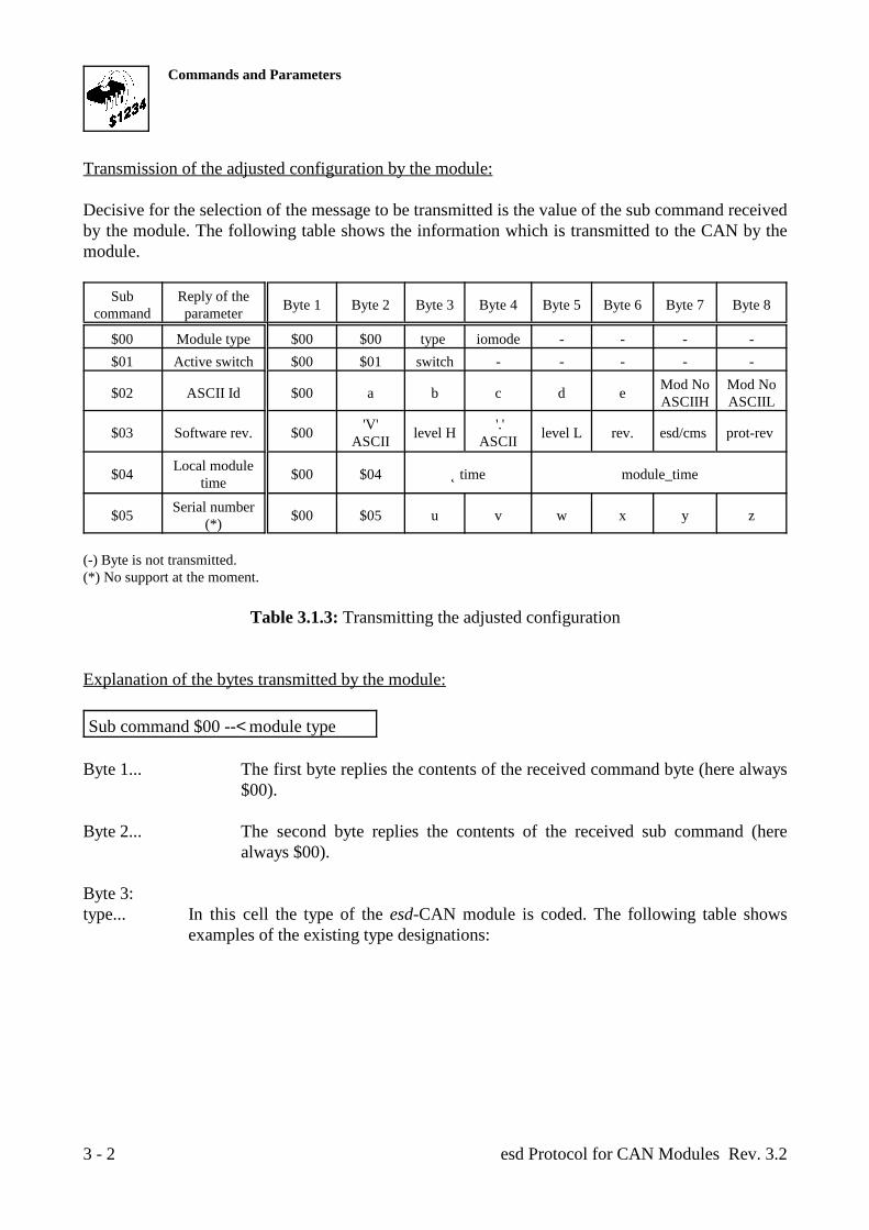
Transmission of the adjusted configuration by the module:
Decisive for the selection of the message to be transmitted is the value of the sub command receivedby the module. The following table shows the information which is transmitted to the CAN by themodule.
Sub Reply of thecommand parameter Byte 1 Byte 2 Byte 3 Byte 4 Byte 5 Byte 6 Byte 7 Byte 8
$00 Module type $00 $00 type iomode - - - - $01 Active switch $00 $01 switch - - - - -
$02 ASCII Id $00 a b c d e Mod No Mod NoASCIIH ASCIIL
$03 Software rev. $00 level H level L rev. esd/cms prot-rev 'V' '.'ASCII ASCII
$04 $00 $04 Îtime module_timeLocal moduletime
$05 $00 $05 u v w x y zSerial number(*)
(-) Byte is not transmitted.(*) No support at the moment.
Table 3.1.3: Transmitting the adjusted configuration
Explanation of the bytes transmitted by the module:
Sub command $00 --< module type
Byte 1... The first byte replies the contents of the received command byte (here always$00).
Byte 2... The second byte replies the contents of the received sub command (herealways $00).
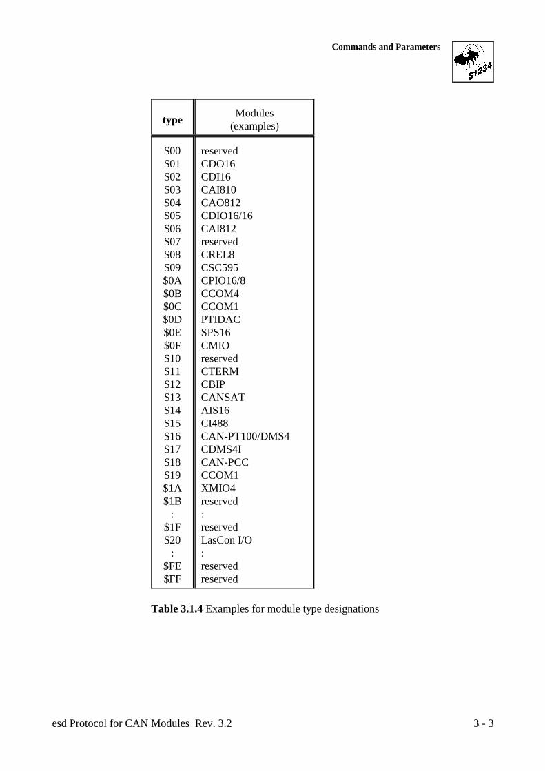
Byte 3:type... In this cell the type of the esd-CAN module is coded. The following table shows
examples of the existing type designations:
Commands and Parameters
esd Protocol for CAN Modules Rev. 3.2 3 - 3
type Modules(examples)
$00 reserved$01 CDO16$02 CDI16$03 CAI810$04 CAO812$05 CDIO16/16$06 CAI812$07 reserved$08 CREL8$09 CSC595$0A CPIO16/8$0B CCOM4$0C CCOM1$0D PTIDAC$0E SPS16$0F CMIO$10 reserved$11 CTERM$12 CBIP$13 CANSAT$14 AIS16$15 CI488$16 CAN-PT100/DMS4$17 CDMS4I$18 CAN-PCC$19 CCOM1$1A XMIO4$1B reserved
: :$1F reserved$20 LasCon I/O
: :$FE reserved$FF reserved
Table 3.1.4 Examples for module type designations
Commands and Parameters
esd Protocol for CAN Modules Rev. 3.23 - 4
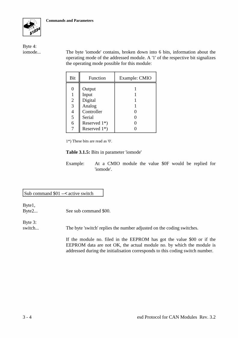
Byte 4:iomode... The byte 'iomode' contains, broken down into 6 bits, information about the
operating mode of the addressed module. A '1' of the respective bit signalizesthe operating mode possible for this module:
Bit Function Example: CMIO
0 Output 11 Input 12 Digital 13 Analog 14 Controller 05 Serial 06 Reserved 1*) 07 Reserved 1*) 0
1*) These bits are read as '0'.
Table 3.1.5: Bits in parameter 'iomode'
Example: At a CMIO module the value $0F would be replied for'iomode'.
Sub command $01 --< active switch
Byte1, Byte2... See sub command $00.
Byte 3:switch... The byte 'switch' replies the number adjusted on the coding switches.
If the module no. filed in the EEPROM has got the value $00 or if theEEPROM data are not OK, the actual module no. by which the module isaddressed during the initialisation corresponds to this coding switch number.
Commands and Parameters
esd Protocol for CAN Modules Rev. 3.2 3 - 5
Sub command $02 --< ASCII Id
Byte 1... See sub command $00.
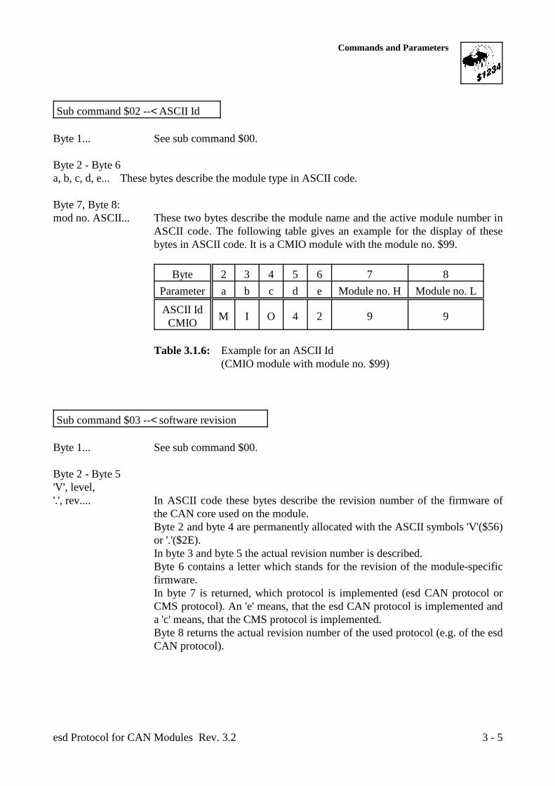
Byte 2 - Byte 6a, b, c, d, e... These bytes describe the module type in ASCII code.
Byte 7, Byte 8:mod no. ASCII... These two bytes describe the module name and the active module number in
ASCII code. The following table gives an example for the display of thesebytes in ASCII code. It is a CMIO module with the module no. $99.
Byte 2 3 4 5 6 7 8Parameter a b c d e Module no. H Module no. L
ASCII IdCMIO M I O 4 2 9 9
Table 3.1.6: Example for an ASCII Id(CMIO module with module no. $99)
Sub command $03 --< software revision
Byte 1... See sub command $00.
Byte 2 - Byte 5'V', level,'.', rev.... In ASCII code these bytes describe the revision number of the firmware of
the CAN core used on the module. Byte 2 and byte 4 are permanently allocated with the ASCII symbols 'V'($56)or '.'($2E). In byte 3 and byte 5 the actual revision number is described. Byte 6 contains a letter which stands for the revision of the module-specificfirmware. In byte 7 is returned, which protocol is implemented (esd CAN protocol orCMS protocol). An 'e' means, that the esd CAN protocol is implemented anda 'c' means, that the CMS protocol is implemented.Byte 8 returns the actual revision number of the used protocol (e.g. of the esdCAN protocol).
Commands and Parameters
esd Protocol for CAN Modules Rev. 3.23 - 6
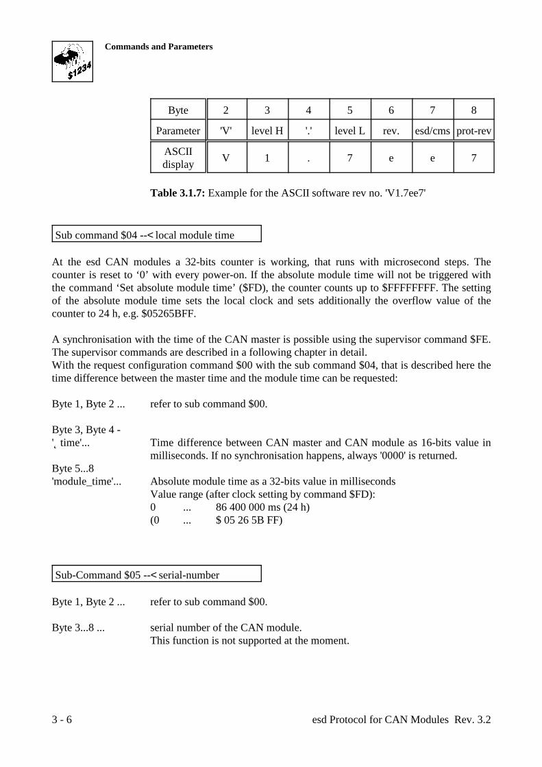
Byte 2 3 4 5 6 7 8
Parameter 'V' level H '.' level L rev. esd/cms prot-rev
ASCIIdisplay V 1 . 7 e e 7
Table 3.1.7: Example for the ASCII software rev no. 'V1.7ee7'
Sub command $04 --< local module time
At the esd CAN modules a 32-bits counter is working, that runs with microsecond steps. Thecounter is reset to ‘0’ with every power-on. If the absolute module time will not be triggered withthe command ‘Set absolute module time’ ($FD), the counter counts up to $FFFFFFFF. The settingof the absolute module time sets the local clock and sets additionally the overflow value of thecounter to 24 h, e.g. $05265BFF.
A synchronisation with the time of the CAN master is possible using the supervisor command $FE.The supervisor commands are described in a following chapter in detail.With the request configuration command $00 with the sub command $04, that is described here thetime difference between the master time and the module time can be requested:
Byte 1, Byte 2 ... refer to sub command $00.
Byte 3, Byte 4 -'Îtime'... Time difference between CAN master and CAN module as 16-bits value in
milliseconds. If no synchronisation happens, always '0000' is returned.Byte 5...8'module_time'... Absolute module time as a 32-bits value in milliseconds
Value range (after clock setting by command $FD):0 ... 86 400 000 ms (24 h)(0 ... $ 05 26 5B FF)
Sub-Command $05 --< serial-number
Byte 1, Byte 2 ... refer to sub command $00.
Byte 3...8 ... serial number of the CAN module.This function is not supported at the moment.
Commands and Parameters
esd Protocol for CAN Modules Rev. 3.2 3 - 7
3.2 System Parameters
With the command $81 the parameters described below are set. By command $01 and the accordingsub command the module is lead to reply the actual parameters.
If the command 'store parameter' (sub command $00) is transmitted to the module, all previouslyinterchanged parameters are stored in the local I²C EEPROM. If the module is reset (RESET) or the supply voltage is switched off, the entered parameters are lostif this command has not been entered before.
After a RESET command or a power-on RESET the module operates with the stored parameters(identifiers etc.). If the programming has been unsuccessful (e.g. no I²C EEPROM or defect) themodule uses the standard parameters (e.g. identifier =< coding switches).
The module no. with which the module is selected at the parameter interchange corresponds to theadjustment of the coding switches (provided no modification had been made so far). By the subcommand $01 it is possible to allocate another module no. to the module. The new number is activeimmediately after the setting and the number adjusted by the coding switches is ignored.
The CAN-status byte offers various information about the condition of the module: It is shown ifthe module had previously not been connected to the CAN, if the default parameters had beenactivated after a RESET, if the last RESET had been caused by a power-on cycle, etc.
By the sub command $03 it is possible to change the CAN bitrate of the module which was adjustedby the configuration jumper of the module. The new bitrate is only activated after the parametershave been stored by sub command $00Command and a RESET has been triggered.
Between the modules and a supervisor (master) a mutual function control by a watchdog protocolsimilar to the CMS specification can occur. By the sub commands $04 and $05 it is possible tointerchange a watchdog identifier and a watchdog time.
Commands and Parameters
esd Protocol for CAN Modules Rev. 3.23 - 8
Byte 1 Byte 2 Byte 3 Byte 4 Byte 5 Byte 6
Function Command Sub command Not used Module no. Parameter 1 Parameter 2
Value $01..$FF$02 status cstat -
Request: $01 $00...$03
Alwaysallocate $00
Selectedmodule no.
= activemodule no.
CTxId$0000...$07FF
Set: $81
$00 store parameter - active modno.
$01 module no. new mod no. -
$03 bitrate bust 0 bust 1
$04 watchdog Id WTxId$0000...$07FF
$05 watchdog time TimeFactorWDLife
$00...$FF
WDtime$0000...$FFFF
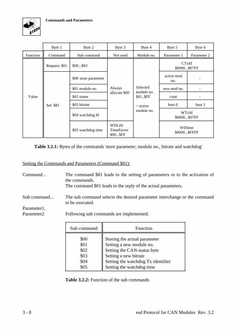
Table 3.2.1: Bytes of the commands 'store parameter, module no., bitrate and watchdog'
Setting the Commands and Parameters (Command $81):
Command... The command $81 leads to the setting of parameters or to the activation ofthe commands.The command $01 leads to the reply of the actual parameters.
Sub command... The sub command selects the desired parameter interchange or the commandto be executed.
Parameter1,Parameter2 Following sub commands are implemented:
Sub command Function
$00 Storing the actual parameter$01 Setting a new module no.$02 Setting the CAN-status byte$03 Setting a new bitrate$04 Setting the watchdog Tx identifier$05 Setting the watchdog time
Table 3.2.2: Function of the sub commands
Commands and Parameters
esd Protocol for CAN Modules Rev. 3.2 3 - 9
The kind of the parameters interchanged to the module depends on theselected sub command:
Sub command $00 --< store parameter
active mod. no... To store all interchanged parameters (also those of other commands) the
actual module no. has to be entered into byte 5 when calling this subcommand.The actual module no. is either the number adjusted by the coding switches(default parameter active) or the number changed by sub command 'setmodule no.'.
Sub command $01 --< set module no.
new. mod. no.. Here the desired new module no. is entered. The module is addressedimmediately after this command by the new module no. The module no.adjusted by the coding switches is ignored.If the new module no. should remain active after a RESET, the parametershave to be stored by the sub command 'store parameters' before a power downor a RESET.
Sub command $02 --< set CAN-status byte
cstat... A 'set' access onto the CAN-status byte sets the bits 2 and 7 of the byte to '0'.All other bits of the status byte remain unchanged, because they serve as readonly information (see also 'requesting the actual parameters').
Bit 2 shows that a CAN error has been detected by the module. The bit servesthe documentation of errors which do not cause a 'standstill' for the CAN, butremain only for a short period. Error arising for a short time can easily beoverlooked, because they make themselves visible only by a temporal limitedflashing of the status LED.The bit is set to '1' when an error has been detected. A 'set' access with anydata (recommended: byte 5 = $00) onto the status byte or each RESET resetthe bit back to '0'.
The CAN-error bit can also be reset by the supervisor command 'reset CANerror' (sub command $05). The other bits remain unchanged by thiscommand.
Commands and Parameters
esd Protocol for CAN Modules Rev. 3.23 - 10
Notes on the internal management of the CAN-error bit:The CAN-error bit is set by the local software if the status bit of theCAN controller 'error status' is activated. (see constat). After the first recognition of a CAN error the controller at first tries totransmit or receive data repeatedly. If it recognizes after severalattempts that the error does not occur anymore, it does not take backits error bit at once. First further successful transmissions have to takeplace to count back the internal error counter again. Supervised Txtransfers which are addressed to other modules are also counted assuccessful transmissions. But if only one module and one CANmaster are installed on the bus, the master possibly has to transmitsome messages first to reset the error counter and therefore reset thecontroller status bit.Therefore it is possible that the CAN-error bit of the CAN-status byteis still active after only one reset, because the error bit of thecontroller is still active.
Bit 7 of the byte has got the designation 'new on bus' and shows if the moduleprocesses for the first time on the CAN: A CAN master is able to evaluate and set the bit to zero to document on themodule that it noted the presence of the module on the CAN. If the bit has gotthe value '1' at the reading, in this application of the bit the module had notbeen found by a master so far after the last RESET.
A 'set' access with any data (recommended: byte 5 = $00) onto the status bytesets the bit onto '0'.
Sub command $03 --< set bitrate
bust0, bust1.. These two bytes set the contents of the registers BTR0 and BTR1 of the CANcontroller 8xC592/82C200 which determine the bitrate of the CAN interface.
An allocation of the register contents to the bit rates can be taken from thetable below.
Contrary to the other commands this parameters only become active after theactual parameter set was stored in the EEPROM (store parameters) and aRESET was triggered on the module.
Commands and Parameters
esd Protocol for CAN Modules Rev. 3.2 3 - 11
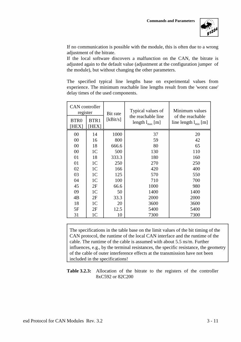
If no communication is possible with the module, this is often due to a wrongadjustment of the bitrate. If the local software discovers a malfunction on the CAN, the bitrate isadjusted again to the default value (adjustment at the configuration jumper ofthe module), but without changing the other parameters.
The specified typical line lengths base on experimental values fromexperience. The minimum reachable line lengths result from the 'worst case'delay times of the used components.
CAN controllerregister Bit rate
[kBit/s]
Typical values of Minimum valuesthe reachable line of the reachable
length l [m] line length l [m]max minBTR0 BTR1[HEX] [HEX]
00 14 1000 37 20 00 16 800 59 42 00 18 666.6 80 65 00 1C 500 130 110 01 18 333.3 180 160 01 1C 250 270 250 02 1C 166 420 400 03 1C 125 570 550 04 1C 100 710 700 45 2F 66.6 1000 980 09 1C 50 1400 1400 4B 2F 33.3 2000 2000 18 1C 20 3600 3600 5F 2F 12.5 5400 5400 31 1C 10 7300 7300
The specifications in the table base on the limit values of the bit timing of theCAN protocol, the runtime of the local CAN interface and the runtime of thecable. The runtime of the cable is assumed with about 5.5 ns/m. Furtherinfluences, e.g., by the terminal resistances, the specific resistance, the geometryof the cable of outer interference effects at the transmission have not beenincluded in the specifications!
Table 3.2.3: Allocation of the bitrate to the registers of the controller8xC592 or 82C200
Commands and Parameters
esd Protocol for CAN Modules Rev. 3.23 - 12
Sub command $04 --< set watchdog Tx identifierSub command $05 --< set watchdog time (guard time)
The watchdog protocol functions with following scheme:
1. After a RESET, the watchdog is inactive. The 'master' interchanges with these subcommands a Tx identifier, a watchdog time (Guard Time) and a life time factor to themodule. Setting the watchdog time to values > '0' and setting the life time factor to values >'0' enables the local watchdog on the module. The watchdog is not activated at that moment!
2. First a remote request has to be received for this Tx identifier or the command 'SupervisorWatchdog' ($FF) has to be received, before the watchdog time is counted down for the firsttime. After this the master has to send a RTR or a supervisor command at the given Txidentifier within the time (WDtime x WDLifeTimeFactor), otherwise a RESET is triggeredat the module.Receiving the RTR or the command shows the module that the master is still active.
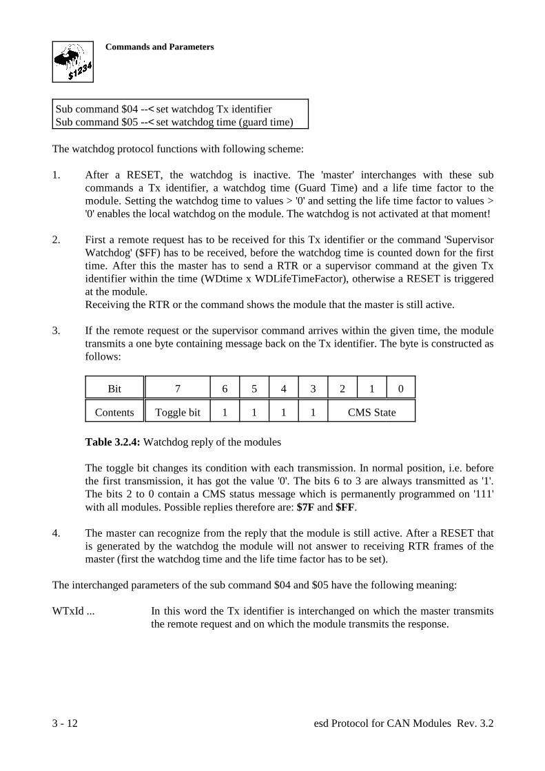
3. If the remote request or the supervisor command arrives within the given time, the moduletransmits a one byte containing message back on the Tx identifier. The byte is constructed asfollows:
Bit 7 6 5 4 3 2 1 0
Contents Toggle bit 1 1 1 1 CMS State
Table 3.2.4: Watchdog reply of the modules
The toggle bit changes its condition with each transmission. In normal position, i.e. beforethe first transmission, it has got the value '0'. The bits 6 to 3 are always transmitted as '1'.The bits 2 to 0 contain a CMS status message which is permanently programmed on '111'with all modules. Possible replies therefore are: $7F and $FF.
4. The master can recognize from the reply that the module is still active. After a RESET thatis generated by the watchdog the module will not answer to receiving RTR frames of themaster (first the watchdog time and the life time factor has to be set).
The interchanged parameters of the sub command $04 and $05 have the following meaning:
WTxId ... In this word the Tx identifier is interchanged on which the master transmitsthe remote request and on which the module transmits the response.
Commands and Parameters
esd Protocol for CAN Modules Rev. 3.2 3 - 13
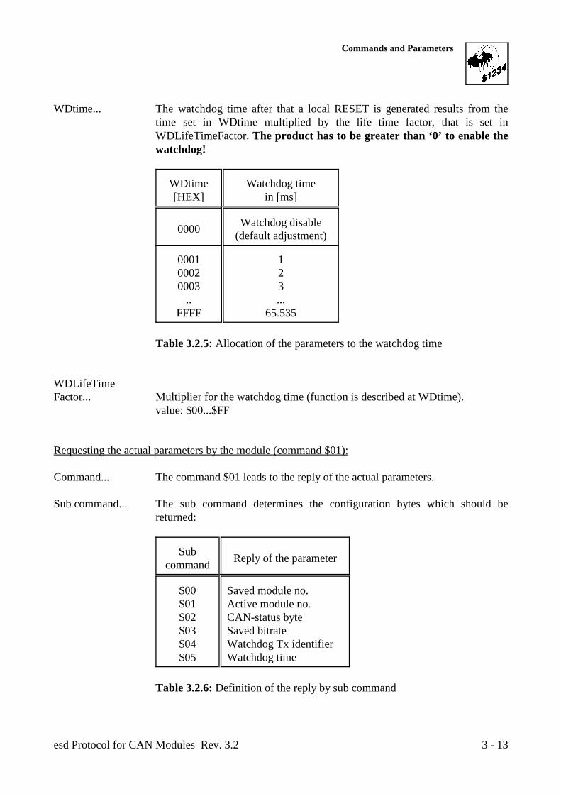
WDtime... The watchdog time after that a local RESET is generated results from thetime set in WDtime multiplied by the life time factor, that is set inWDLifeTimeFactor. The product has to be greater than ‘0’ to enable thewatchdog!
WDtime Watchdog time[HEX] in [ms]
0000 Watchdog disable(default adjustment)
0001 10002 20003 3
.. ...FFFF 65.535
Table 3.2.5: Allocation of the parameters to the watchdog time
WDLifeTimeFactor... Multiplier for the watchdog time (function is described at WDtime).
value: $00...$FF
Requesting the actual parameters by the module (command $01):
Command... The command $01 leads to the reply of the actual parameters.
Sub command... The sub command determines the configuration bytes which should bereturned:
Subcommand Reply of the parameter
$00 Saved module no.$01 Active module no.$02 CAN-status byte$03 Saved bitrate$04 Watchdog Tx identifier$05 Watchdog time
Table 3.2.6: Definition of the reply by sub command
Commands and Parameters
esd Protocol for CAN Modules Rev. 3.23 - 14
Parameter 1 and 2... With these parameters it is reported to the module onto which CAN Id itshould transmit the requested reply.
Decisive for the selection of the requested message is the sub command value received by themodule.
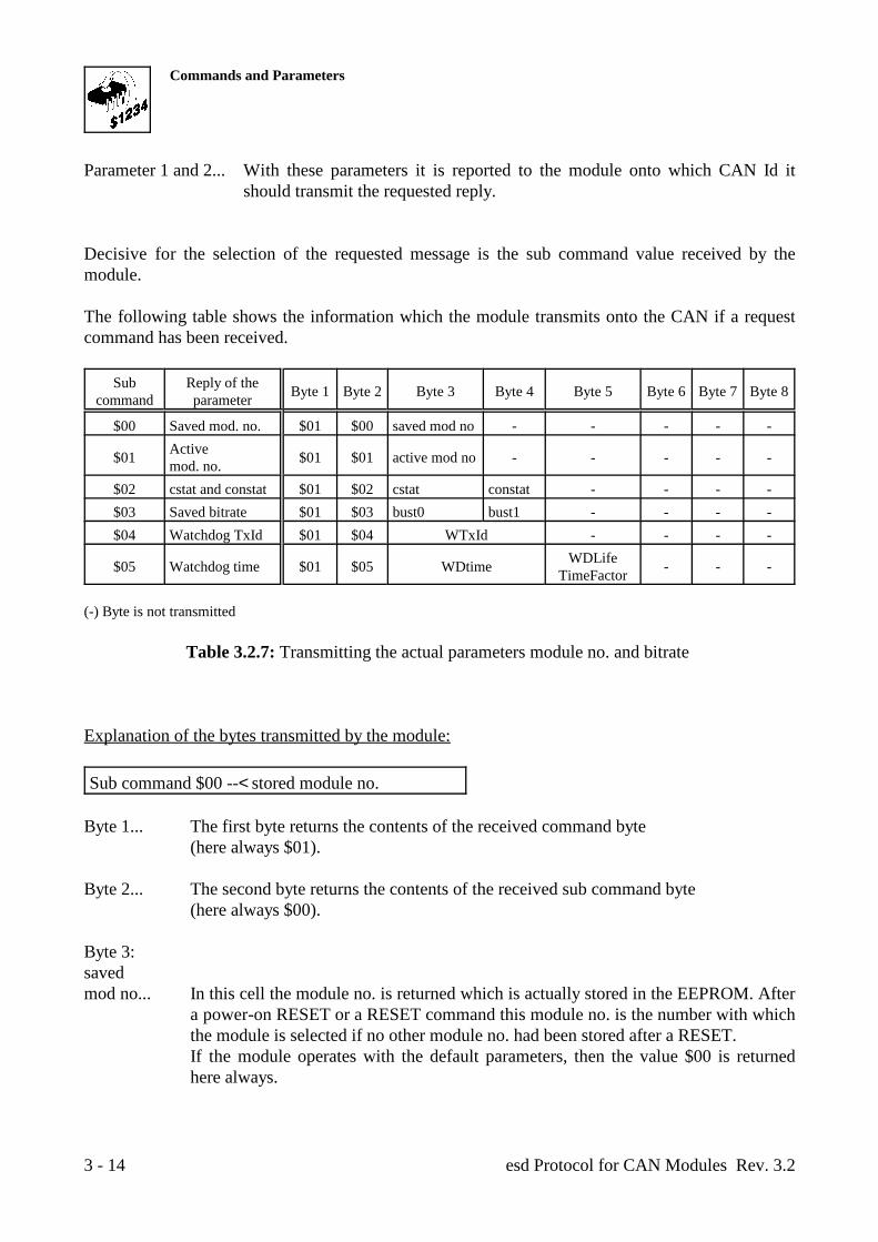
The following table shows the information which the module transmits onto the CAN if a requestcommand has been received.
Sub Reply of thecommand parameter Byte 1 Byte 2 Byte 3 Byte 4 Byte 5 Byte 6 Byte 7 Byte 8
$00 Saved mod. no. $01 $00 saved mod no - - - - -
$01 $01 $01 active mod no - - - - -Active mod. no.
$02 cstat and constat $01 $02 cstat constat - - - -$03 Saved bitrate $01 $03 bust0 bust1 - - - -$04 Watchdog TxId $01 $04 WTxId - - - -
$05 Watchdog time $01 $05 WDtime - - -WDLifeTimeFactor
(-) Byte is not transmitted
Table 3.2.7: Transmitting the actual parameters module no. and bitrate
Explanation of the bytes transmitted by the module:
Sub command $00 --< stored module no.
Byte 1... The first byte returns the contents of the received command byte (here always $01).
Byte 2... The second byte returns the contents of the received sub command byte(here always $00).
Byte 3:savedmod no... In this cell the module no. is returned which is actually stored in the EEPROM. After
a power-on RESET or a RESET command this module no. is the number with whichthe module is selected if no other module no. had been stored after a RESET.If the module operates with the default parameters, then the value $00 is returnedhere always.
Commands and Parameters
esd Protocol for CAN Modules Rev. 3.2 3 - 15
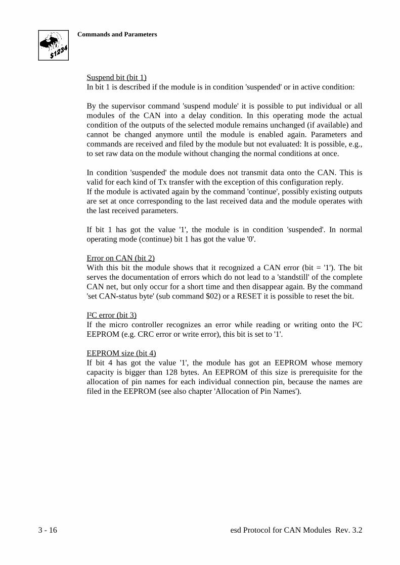
Sub command $01 --< actual module no.
Byte1, Byte2... See sub command $00.
Byte 3:activemod no... Here the module no. is returned which is active at the moment. This number is
identical with the number of this INIT Id entered into byte 4.
Sub command $02 --< CAN-status byte
Byte1, Byte2... See sub command $00.
cstat... Byte 3 describes status information about the condition of the CAN components ofthe selected module (see the following table).
Bit Designation
0 Power-down RESET1 Suspend bit2 Error on CAN3 I²C error4 EEPROM size5 I²C busy6 Default wake up7 New on bus
Table 3.2.8: Bits of the parameter 'cstat'
Explanation of the bits of parameter 'cstat':
Power-down RESET (bit 0)Bit 0 shows if the last RESET on the module had been triggered by a power-downRESET. If the bit has got the value '1', the last RESET had been triggered byremoving the supply voltage. For all other RESET causes (RESET by supervisorcommand, RESET by EMERGENCY STOP) the bit is '0'.
Commands and Parameters
esd Protocol for CAN Modules Rev. 3.23 - 16
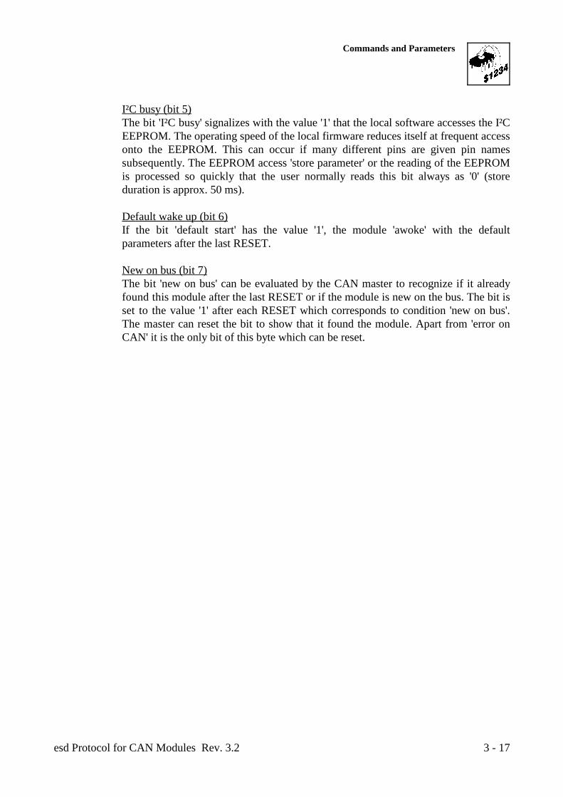
Suspend bit (bit 1)In bit 1 is described if the module is in condition 'suspended' or in active condition:
By the supervisor command 'suspend module' it is possible to put individual or allmodules of the CAN into a delay condition. In this operating mode the actualcondition of the outputs of the selected module remains unchanged (if available) andcannot be changed anymore until the module is enabled again. Parameters andcommands are received and filed by the module but not evaluated: It is possible, e.g.,to set raw data on the module without changing the normal conditions at once.
In condition 'suspended' the module does not transmit data onto the CAN. This isvalid for each kind of Tx transfer with the exception of this configuration reply.If the module is activated again by the command 'continue', possibly existing outputsare set at once corresponding to the last received data and the module operates withthe last received parameters.
If bit 1 has got the value '1', the module is in condition 'suspended'. In normaloperating mode (continue) bit 1 has got the value '0'.
Error on CAN (bit 2)With this bit the module shows that it recognized a CAN error (bit = '1'). The bitserves the documentation of errors which do not lead to a 'standstill' of the completeCAN net, but only occur for a short time and then disappear again. By the command'set CAN-status byte' (sub command $02) or a RESET it is possible to reset the bit.
I²C error (bit 3)If the micro controller recognizes an error while reading or writing onto the I²CEEPROM (e.g. CRC error or write error), this bit is set to '1'.
EEPROM size (bit 4)If bit 4 has got the value '1', the module has got an EEPROM whose memorycapacity is bigger than 128 bytes. An EEPROM of this size is prerequisite for theallocation of pin names for each individual connection pin, because the names arefiled in the EEPROM (see also chapter 'Allocation of Pin Names').
Commands and Parameters
esd Protocol for CAN Modules Rev. 3.2 3 - 17
I²C busy (bit 5)The bit 'I²C busy' signalizes with the value '1' that the local software accesses the I²CEEPROM. The operating speed of the local firmware reduces itself at frequent accessonto the EEPROM. This can occur if many different pins are given pin namessubsequently. The EEPROM access 'store parameter' or the reading of the EEPROMis processed so quickly that the user normally reads this bit always as '0' (storeduration is approx. 50 ms).
Default wake up (bit 6)If the bit 'default start' has the value '1', the module 'awoke' with the defaultparameters after the last RESET.
New on bus (bit 7)The bit 'new on bus' can be evaluated by the CAN master to recognize if it alreadyfound this module after the last RESET or if the module is new on the bus. The bit isset to the value '1' after each RESET which corresponds to condition 'new on bus'.The master can reset the bit to show that it found the module. Apart from 'error onCAN' it is the only bit of this byte which can be reset.
Commands and Parameters
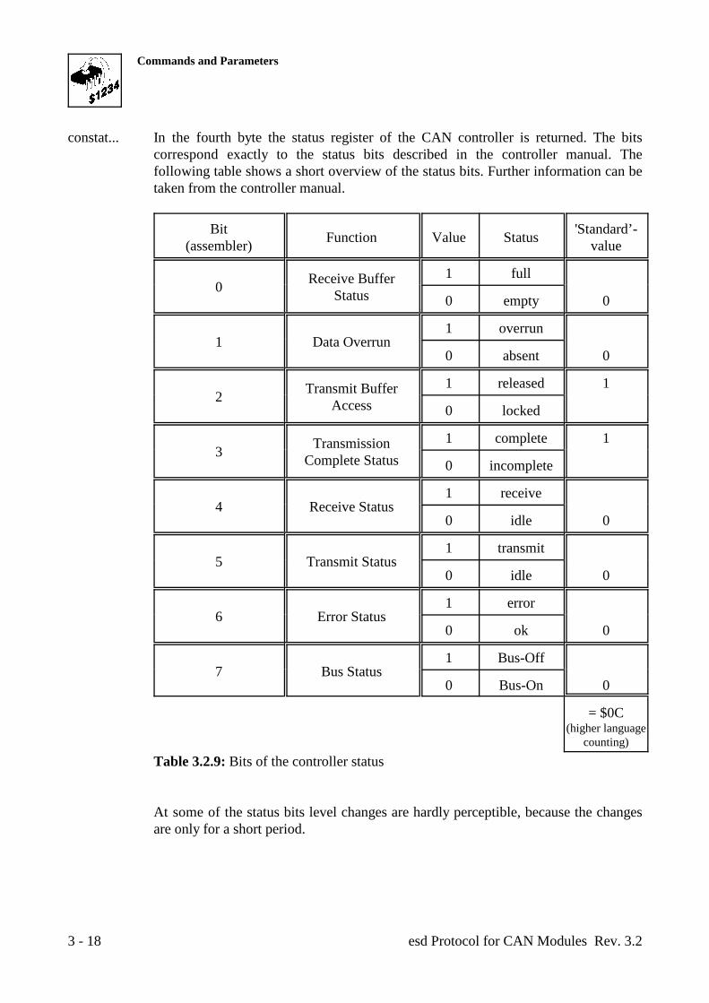
esd Protocol for CAN Modules Rev. 3.23 - 18
constat... In the fourth byte the status register of the CAN controller is returned. The bitscorrespond exactly to the status bits described in the controller manual. Thefollowing table shows a short overview of the status bits. Further information can betaken from the controller manual.
Bit 'Standard’-(assembler) valueFunction Value Status
0 Receive BufferStatus
1 full
0 empty 0
1 Data Overrun1 overrun
0 absent 0
2 Transmit BufferAccess
1 released 1
0 locked
3 TransmissionComplete Status
1 complete 1
0 incomplete
4 Receive Status1 receive
0 idle 0
5 Transmit Status1 transmit
0 idle 0
6 Error Status1 error
0 ok 0
7 Bus Status1 Bus-Off
0 Bus-On 0
= $0C(higher language
counting)
Table 3.2.9: Bits of the controller status
At some of the status bits level changes are hardly perceptible, because the changesare only for a short period.
Commands and Parameters
esd Protocol for CAN Modules Rev. 3.2 3 - 19
Sub command $03 --< stored bitrate
Byte1, Byte2... See sub command $00.
Byte 3, 4:bust 0,bust1 ... These two bytes describe the contents of the registers BTR0 and BTR1 of the CAN
controller 8xC592/82C200 which determine the bitrate of the CAN interface. Theallocation of the register contents to the bit rates has already been explained in thedescription of setting these registers.
Sub command $04 --< watchdog Tx identifier
Byte1, Byte2... See sub command $00.
Byte 3, 4:WTxId-H,WTxId-L ... These two bytes return Tx identifiers on which the module transmits the watchdog
reply.
Sub command $05 --< watchdog time
Byte1, Byte2... See sub command $00.
Byte 3, 4:WDtime... Here the watchdog time is returned (value range see 'Setting the watchdog time').
Byte 5:WDLifeTimeFactor... Return of the Life Time Factor ($00...$FF).
Commands and Parameters
esd Protocol for CAN Modules Rev. 3.23 - 20
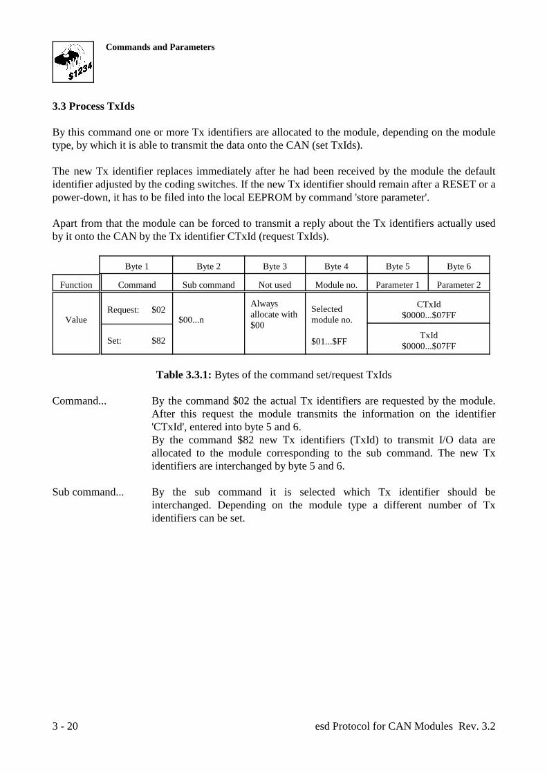
3.3 Process TxIds
By this command one or more Tx identifiers are allocated to the module, depending on the moduletype, by which it is able to transmit the data onto the CAN (set TxIds).
The new Tx identifier replaces immediately after he had been received by the module the defaultidentifier adjusted by the coding switches. If the new Tx identifier should remain after a RESET or apower-down, it has to be filed into the local EEPROM by command 'store parameter'.
Apart from that the module can be forced to transmit a reply about the Tx identifiers actually usedby it onto the CAN by the Tx identifier CTxId (request TxIds).
Byte 1 Byte 2 Byte 3 Byte 4 Byte 5 Byte 6
Function Command Sub command Not used Module no. Parameter 1 Parameter 2
Value $00...n module no.Request: $02
Alwaysallocate with$00
Selected
$01...$FF
CTxId$0000...$07FF
Set: $82 TxId$0000...$07FF
Table 3.3.1: Bytes of the command set/request TxIds
Command... By the command $02 the actual Tx identifiers are requested by the module.After this request the module transmits the information on the identifier'CTxId', entered into byte 5 and 6.By the command $82 new Tx identifiers (TxId) to transmit I/O data areallocated to the module corresponding to the sub command. The new Txidentifiers are interchanged by byte 5 and 6.
Sub command... By the sub command it is selected which Tx identifier should beinterchanged. Depending on the module type a different number of Txidentifiers can be set.
Commands and Parameters
esd Protocol for CAN Modules Rev. 3.2 3 - 21
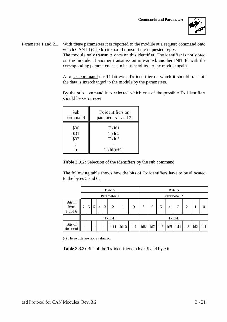
Parameter 1 and 2... With these parameters it is reported to the module at a request command ontowhich CAN Id (CTxId) it should transmit the requested reply.The module only transmits once on this identifier. The identifier is not storedon the module. If another transmission is wanted, another INIT Id with thecorresponding parameters has to be transmitted to the module again.
At a set command the 11 bit wide Tx identifier on which it should transmitthe data is interchanged to the module by the parameters.
By the sub command it is selected which one of the possible Tx identifiersshould be set or reset:
Sub Tx identifiers oncommand parameters 1 and 2
$00 TxId1$01 TxId2$02 TxId3
: :n TxId(n+1)
Table 3.3.2: Selection of the identifiers by the sub command
The following table shows how the bits of Tx identifiers have to be allocatedto the bytes 5 and 6:
Byte 5 Byte 6Parameter 1 Parameter 2
Bits inbyte 7 6 5 4 3 2 1 0 7 6 5 4 3 2 1 0
5 and 6
TxId-H TxId-L
Bits ofthe TxId - - - - - id11 id10 id9 id8 id7 id6 id5 id4 id3 id2 id1
(-) These bits are not evaluated.
Table 3.3.3: Bits of the Tx identifiers in byte 5 and byte 6
Commands and Parameters
esd Protocol for CAN Modules Rev. 3.23 - 22
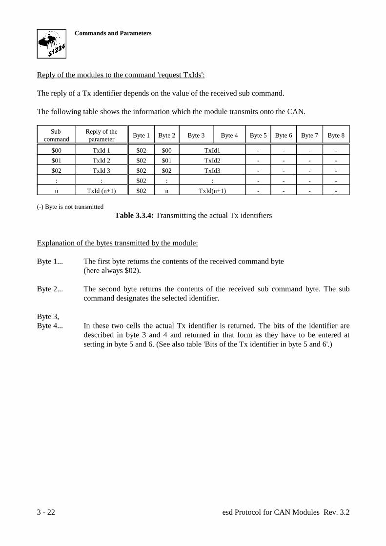
Reply of the modules to the command 'request TxIds':
The reply of a Tx identifier depends on the value of the received sub command.
The following table shows the information which the module transmits onto the CAN.
Sub Reply of thecommand parameter Byte 1 Byte 2 Byte 3 Byte 4 Byte 5 Byte 6 Byte 7 Byte 8
$00 TxId 1 $02 $00 TxId1 - - - -$01 TxId 2 $02 $01 TxId2 - - - -$02 TxId 3 $02 $02 TxId3 - - - -
: : $02 : : - - - -n TxId (n+1) $02 n TxId(n+1) - - - -
(-) Byte is not transmittedTable 3.3.4: Transmitting the actual Tx identifiers
Explanation of the bytes transmitted by the module:
Byte 1... The first byte returns the contents of the received command byte (here always $02).
Byte 2... The second byte returns the contents of the received sub command byte. The subcommand designates the selected identifier.
Byte 3,Byte 4... In these two cells the actual Tx identifier is returned. The bits of the identifier are
described in byte 3 and 4 and returned in that form as they have to be entered atsetting in byte 5 and 6. (See also table 'Bits of the Tx identifier in byte 5 and 6'.)
Commands and Parameters
esd Protocol for CAN Modules Rev. 3.2 3 - 23
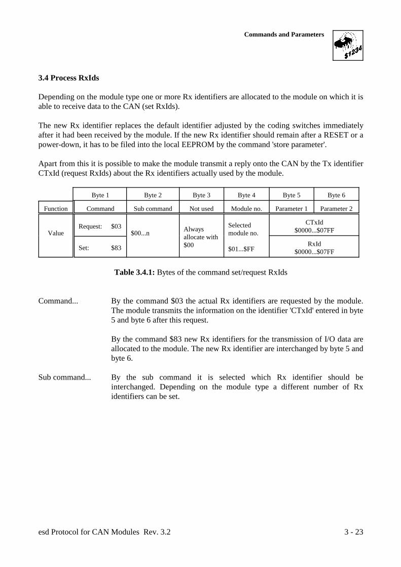
3.4 Process RxIds
Depending on the module type one or more Rx identifiers are allocated to the module on which it isable to receive data to the CAN (set RxIds).
The new Rx identifier replaces the default identifier adjusted by the coding switches immediatelyafter it had been received by the module. If the new Rx identifier should remain after a RESET or apower-down, it has to be filed into the local EEPROM by the command 'store parameter'.
Apart from this it is possible to make the module transmit a reply onto the CAN by the Tx identifierCTxId (request RxIds) about the Rx identifiers actually used by the module.
Byte 1 Byte 2 Byte 3 Byte 4 Byte 5 Byte 6
Function Command Sub command Not used Module no. Parameter 1 Parameter 2
Value $00...n module no.Request: $03 Always
allocate with $00
Selected
$01...$FF
CTxId$0000...$07FF
Set: $83 RxId$0000...$07FF
Table 3.4.1: Bytes of the command set/request RxIds
Command... By the command $03 the actual Rx identifiers are requested by the module.The module transmits the information on the identifier 'CTxId' entered in byte5 and byte 6 after this request.
By the command $83 new Rx identifiers for the transmission of I/O data areallocated to the module. The new Rx identifier are interchanged by byte 5 andbyte 6.
Sub command... By the sub command it is selected which Rx identifier should beinterchanged. Depending on the module type a different number of Rxidentifiers can be set.
Commands and Parameters
esd Protocol for CAN Modules Rev. 3.23 - 24
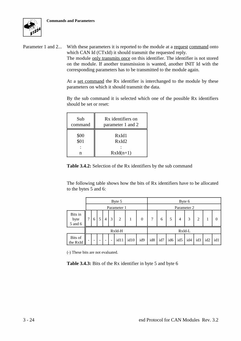
Parameter 1 and 2... With these parameters it is reported to the module at a request command ontowhich CAN Id (CTxId) it should transmit the requested reply.The module only transmits once on this identifier. The identifier is not storedon the module. If another transmission is wanted, another INIT Id with thecorresponding parameters has to be transmitted to the module again.
At a set command the Rx identifier is interchanged to the module by theseparameters on which it should transmit the data.
By the sub command it is selected which one of the possible Rx identifiersshould be set or reset:
Sub Rx identifiers oncommand parameter 1 and 2
$00 RxId1$01 RxId2
: :n RxId(n+1)
Table 3.4.2: Selection of the Rx identifiers by the sub command
The following table shows how the bits of Rx identifiers have to be allocatedto the bytes 5 and 6:
Byte 5 Byte 6Parameter 1 Parameter 2
Bits inbyte 7 6 5 4 3 2 1 0 7 6 5 4 3 2 1 0
5 and 6
RxId-H RxId-L
Bits ofthe RxId - - - - - id11 id10 id9 id8 id7 id6 id5 id4 id3 id2 id1
(-) These bits are not evaluated.
Table 3.4.3: Bits of the Rx identifier in byte 5 and byte 6
Commands and Parameters
esd Protocol for CAN Modules Rev. 3.2 3 - 25
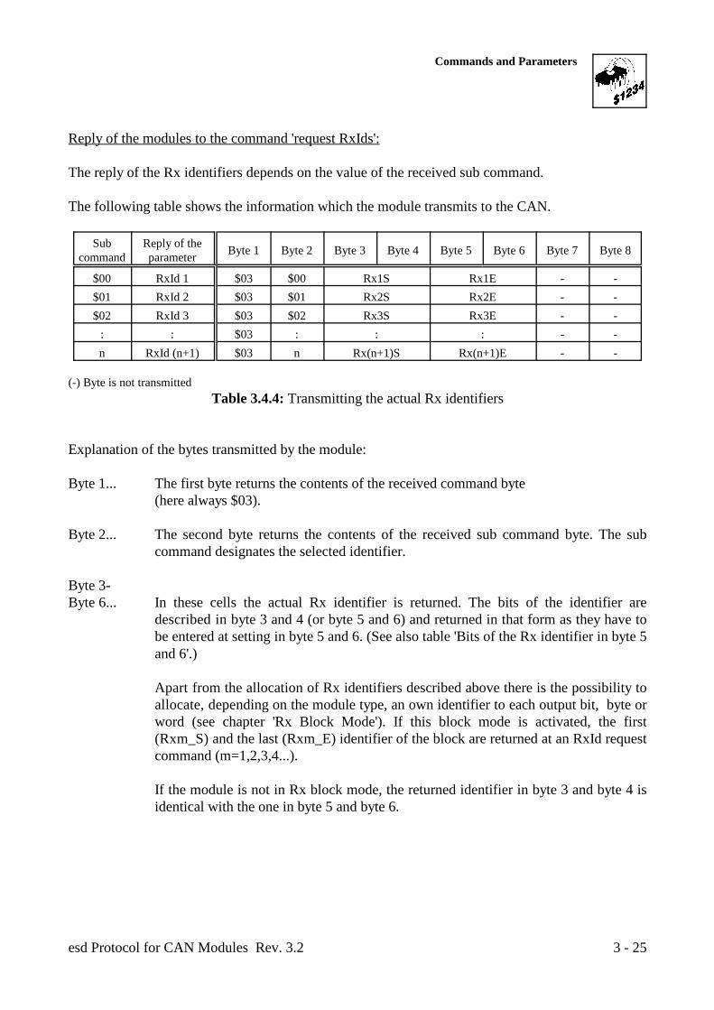
Reply of the modules to the command 'request RxIds':
The reply of the Rx identifiers depends on the value of the received sub command.
The following table shows the information which the module transmits to the CAN.
Sub Reply of thecommand parameter Byte 1 Byte 2 Byte 3 Byte 4 Byte 5 Byte 6 Byte 7 Byte 8
$00 RxId 1 $03 $00 Rx1S Rx1E - -$01 RxId 2 $03 $01 Rx2S Rx2E - -$02 RxId 3 $03 $02 Rx3S Rx3E - -
: : $03 : : : - -n RxId (n+1) $03 n Rx(n+1)S Rx(n+1)E - -
(-) Byte is not transmittedTable 3.4.4: Transmitting the actual Rx identifiers
Explanation of the bytes transmitted by the module:
Byte 1... The first byte returns the contents of the received command byte (here always $03).
Byte 2... The second byte returns the contents of the received sub command byte. The subcommand designates the selected identifier.
Byte 3-Byte 6... In these cells the actual Rx identifier is returned. The bits of the identifier are
described in byte 3 and 4 (or byte 5 and 6) and returned in that form as they have tobe entered at setting in byte 5 and 6. (See also table 'Bits of the Rx identifier in byte 5and 6'.)
Apart from the allocation of Rx identifiers described above there is the possibility toallocate, depending on the module type, an own identifier to each output bit, byte orword (see chapter 'Rx Block Mode'). If this block mode is activated, the first(Rxm_S) and the last (Rxm_E) identifier of the block are returned at an RxId requestcommand (m=1,2,3,4...).
If the module is not in Rx block mode, the returned identifier in byte 3 and byte 4 isidentical with the one in byte 5 and byte 6.
Commands and Parameters
esd Protocol for CAN Modules Rev. 3.23 - 26
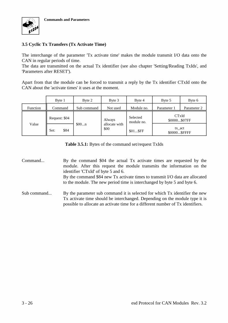
3.5 Cyclic Tx Transfers (Tx Activate Time)
The interchange of the parameter 'Tx activate time' makes the module transmit I/O data onto theCAN in regular periods of time. The data are transmitted on the actual Tx identifier (see also chapter 'Setting/Reading TxIds', and'Parameters after RESET').
Apart from that the module can be forced to transmit a reply by the Tx identifier CTxId onto theCAN about the 'activate times' it uses at the moment.
Byte 1 Byte 2 Byte 3 Byte 4 Byte 5 Byte 6
Function Command Sub command Not used Module no. Parameter 1 Parameter 2
Value $00...n allocate with
Request: $04 Always
$00
Selectedmodule no.
$01...$FF
CTxId$0000...$07FF
Set: $84 tx_act$0000...$FFFF
Table 3.5.1: Bytes of the command set/request TxIds
Command... By the command $04 the actual Tx activate times are requested by themodule. After this request the module transmits the information on theidentifier 'CTxId' of byte 5 and 6.By the command $84 new Tx activate times to transmit I/O data are allocatedto the module. The new period time is interchanged by byte 5 and byte 6.
Sub command... By the parameter sub command it is selected for which Tx identifier the newTx activate time should be interchanged. Depending on the module type it ispossible to allocate an activate time for a different number of Tx identifiers.
Commands and Parameters
esd Protocol for CAN Modules Rev. 3.2 3 - 27
Parameter 1 and 2... By these parameters it is reported to the module at a request command ontowhich CAN Id (CTxId) it should transmit the requested reply.The module transmits only once on this identifier. The identifier is not storedon the module. If another transmission is wanted, another INIT Id with thecorresponding parameters has to be transmitted to the module again.
At a set command the activate time is interchanged to the module by theseparameters.
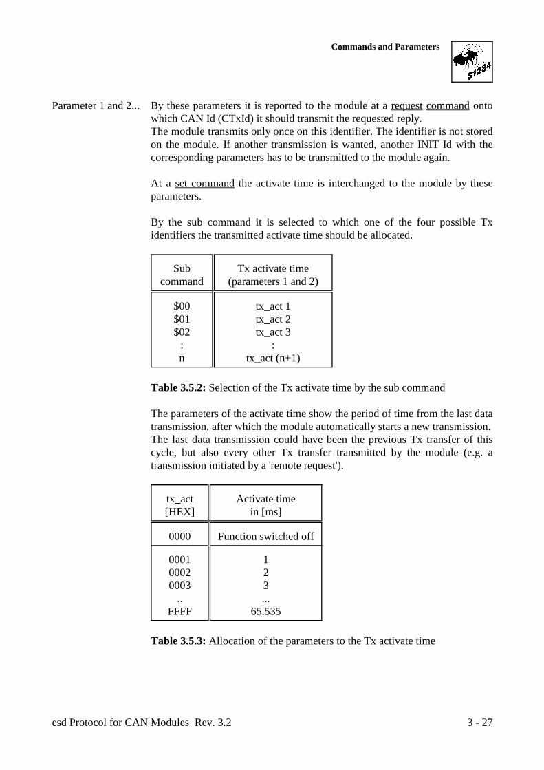
By the sub command it is selected to which one of the four possible Txidentifiers the transmitted activate time should be allocated.
Sub Tx activate timecommand (parameters 1 and 2)
$00 tx_act 1$01 tx_act 2$02 tx_act 3
: :n tx_act (n+1)
Table 3.5.2: Selection of the Tx activate time by the sub command
The parameters of the activate time show the period of time from the last datatransmission, after which the module automatically starts a new transmission.The last data transmission could have been the previous Tx transfer of thiscycle, but also every other Tx transfer transmitted by the module (e.g. atransmission initiated by a 'remote request').
tx_act Activate time[HEX] in [ms]
0000 Function switched off
0001 10002 20003 3
.. ...FFFF 65.535
Table 3.5.3: Allocation of the parameters to the Tx activate time
Commands and Parameters
esd Protocol for CAN Modules Rev. 3.23 - 28
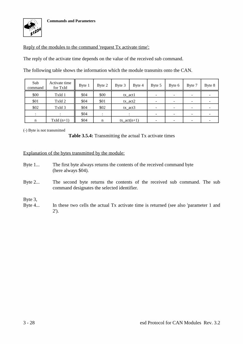
Reply of the modules to the command 'request Tx activate time':
The reply of the activate time depends on the value of the received sub command.
The following table shows the information which the module transmits onto the CAN.
Sub Activate timecommand for TxId Byte 1 Byte 2 Byte 3 Byte 4 Byte 5 Byte 6 Byte 7 Byte 8
$00 TxId 1 $04 $00 tx_act1 - - - -$01 TxId 2 $04 $01 tx_act2 - - - -$02 TxId 3 $04 $02 tx_act3 - - - -
: : $04 : : - - - -n TxId (n+1) $04 n tx_act(n+1) - - - -
(-) Byte is not transmittedTable 3.5.4: Transmitting the actual Tx activate times
Explanation of the bytes transmitted by the module:
Byte 1... The first byte always returns the contents of the received command byte(here always $04).
Byte 2... The second byte returns the contents of the received sub command. The subcommand designates the selected identifier.
Byte 3,Byte 4... In these two cells the actual Tx activate time is returned (see also 'parameter 1 and
2').
Commands and Parameters
esd Protocol for CAN Modules Rev. 3.2 3 - 29
3.6 Process Module Memory
3.6.1 Internal RAM and XRAM, EEPROM
By this command it is possible to display or change the contents of the local memories and to set orread the microcontroller’s ports. The memories contain the parameters which have already beendescribed and are still to come. The contents of the memory should only be changed by thedescribed parameter set commands and not by the command 'process module memory'.
If the command 'store parameter' is called after the modification of a memory cell of the internalRAM or XRAM of the CAN controller, the new data are filed in the local EEPROM. At directaccesses onto the EEPROM the transferred data are filed in the EEPROM at once. The user should not change the cells of the local memories by this command, because thefunctioning of the modules cannot be guaranteed at improper programming of the memories!
At write accesses onto the memory the address is interchanged by the sub command 1, the desiredmemory components by sub command 2 and the data by parameter 1. The user should only read the controller ports, because most of the ports are used for controllingthe local circuits and are set by the firmware!
The request of the port status is permitted. The assignment of the ports depends of the module type.The assignament of the ports is shown in the circuit diagrams.
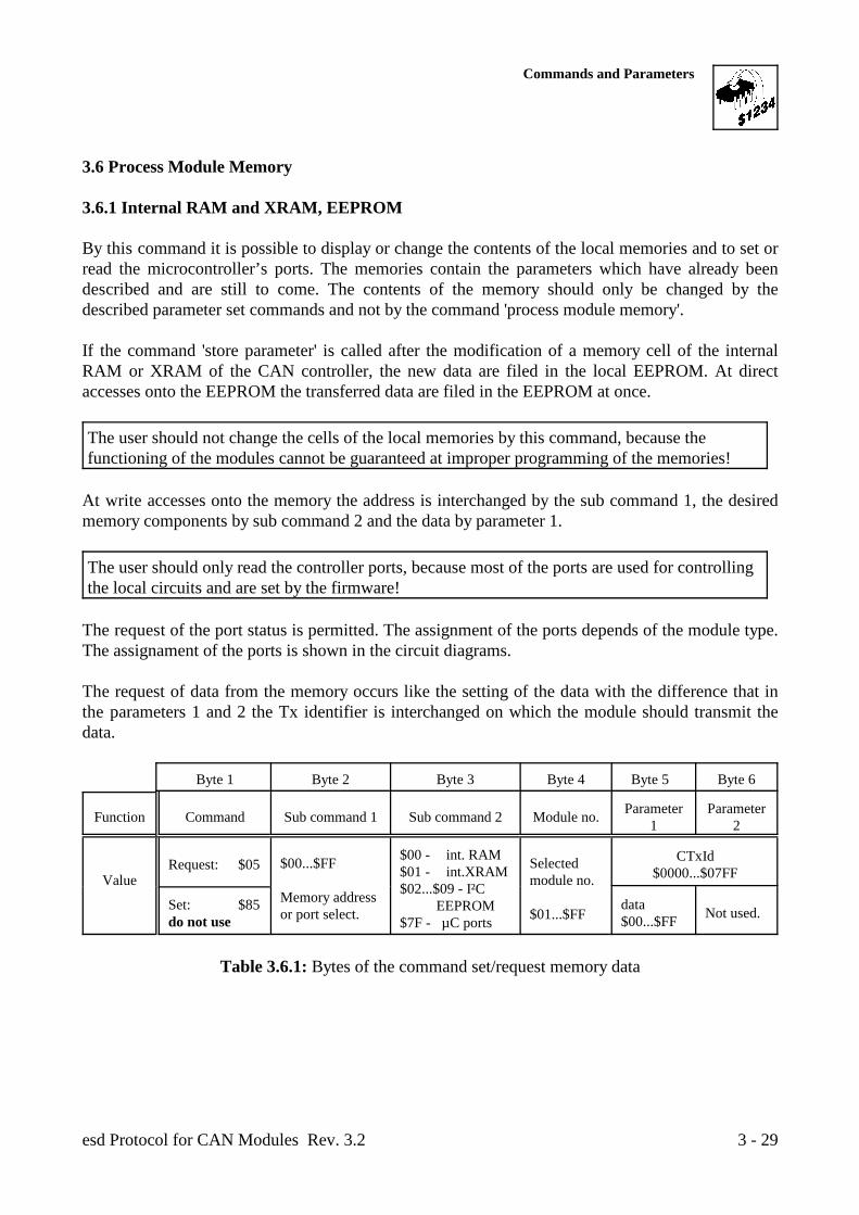
The request of data from the memory occurs like the setting of the data with the difference that inthe parameters 1 and 2 the Tx identifier is interchanged on which the module should transmit thedata.
Byte 1 Byte 2 Byte 3 Byte 4 Byte 5 Byte 6
Function Command Sub command 1 Sub command 2 Module no. Parameter Parameter1 2
Value module no.Request: $05 $00...$FF Selected
Memory addressor port select. $01...$FF
$00 - int. RAM$01 - int.XRAM$02...$09 - I²C EEPROM$7F - µC ports
CTxId$0000...$07FF
Set: $85do not use
data$00...$FF Not used.
Table 3.6.1: Bytes of the command set/request memory data
Commands and Parameters
esd Protocol for CAN Modules Rev. 3.23 - 30
Command... By the command $05 the memory data are requested by the module. Afterthis request the module transmits the information on the identifier 'CTxId' ofbyte 5 and 6.By the command $85 the available data of the memory cell selected by thesub commands is overwritten or the controller ports are set.
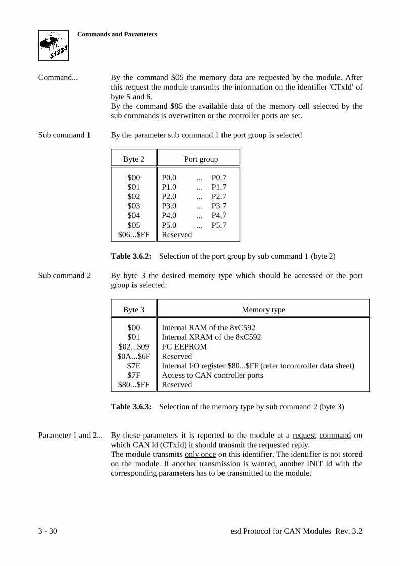
Sub command 1 By the parameter sub command 1 the port group is selected.
Byte 2 Port group
$00 P0.0 ... P0.7$01 P1.0 ... P1.7$02 P2.0 ... P2.7$03 P3.0 ... P3.7$04 P4.0 ... P4.7$05 P5.0 ... P5.7
$06...$FF Reserved
Table 3.6.2: Selection of the port group by sub command 1 (byte 2)
Sub command 2 By byte 3 the desired memory type which should be accessed or the portgroup is selected:
Byte 3 Memory type
$00 Internal RAM of the 8xC592$01 Internal XRAM of the 8xC592
$02...$09 I²C EEPROM$0A...$6F Reserved
$7E Internal I/O register $80...$FF (refer tocontroller data sheet)$7F Access to CAN controller ports
$80...$FF Reserved
Table 3.6.3: Selection of the memory type by sub command 2 (byte 3)
Parameter 1 and 2... By these parameters it is reported to the module at a request command onwhich CAN Id (CTxId) it should transmit the requested reply.The module transmits only once on this identifier. The identifier is not storedon the module. If another transmission is wanted, another INIT Id with thecorresponding parameters has to be transmitted to the module.
Commands and Parameters
esd Protocol for CAN Modules Rev. 3.2 3 - 31
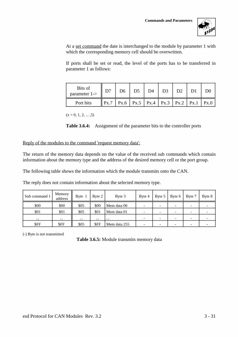
At a set command the date is interchanged to the module by parameter 1 withwhich the corresponding memory cell should be overwritten.
If ports shall be set or read, the level of the ports has to be transferred inparameter 1 as follows:
Bits ofparameter 1-> D7 D6 D5 D4 D3 D2 D1 D0
Port bits Px.7 Px.6 Px.5 Px.4 Px.3 Px.2 Px.1 Px.0
(x = 0, 1, 2, ... ,5)
Table 3.6.4: Assignment of the parameter bits to the controller ports
Reply of the modules to the command 'request memory data':
The return of the memory data depends on the value of the received sub commands which containinformation about the memory type and the address of the desired memory cell or the port group.
The following table shows the information which the module transmits onto the CAN.
The reply does not contain information about the selected memory type.
Sub command 1 Byte 1 Byte 2 Byte 3 Byte 4 Byte 5 Byte 6 Byte 7 Byte 8Memoryaddress
$00 $00 $05 $00 Mem data 00 - - - - -$01 $01 $05 $01 Mem data 01 - - - - -... ... ... ... ... - - - - -
$FF $FF $05 $FF Mem data 255 - - - - -
(-) Byte is not transmittedTable 3.6.5: Module transmits memory data

Commands and Parameters
esd Protocol for CAN Modules Rev. 3.23 - 32
Sub command 1 Byte 1 Byte 2 Byte 3 Byte 4 Byte 5 Byte 6 Byte 7 Byte 8Portgroup
$00 P0.x $05 $00 Ports P0.0 ... P0.7 - - - - -$01 P1.x $05 $01 Ports P1.0 ... P1.7 - - - - -... ... ... ... ... - - - - -
$FF P5.x $05 $FF Ports P5.0 ... P1.7 - - - - -
(-) Byte is not transmittedx = 0, 1, 2, ... ,5
Table 3.6.6: Module transmits controller ports status
Explanation of the bytes transmitted by the module:
Byte 1... The first byte returns the contents of the received command byte(here always $05).
Byte 2... The second byte returns the contents of the received sub command byte (subcommand 1). The sub command designates the memory address.
Byte 3:Mem data... In case of memory cell request this cell contains the actual date of the selected
memory.
Byte 3:Ports... In case of controller port request this cell contains the actual state of the port bits.
The assignment of the ports to the parameter bits is shown at the previous page.
Commands and Parameters
esd Protocol for CAN Modules Rev. 3.2 3 - 33
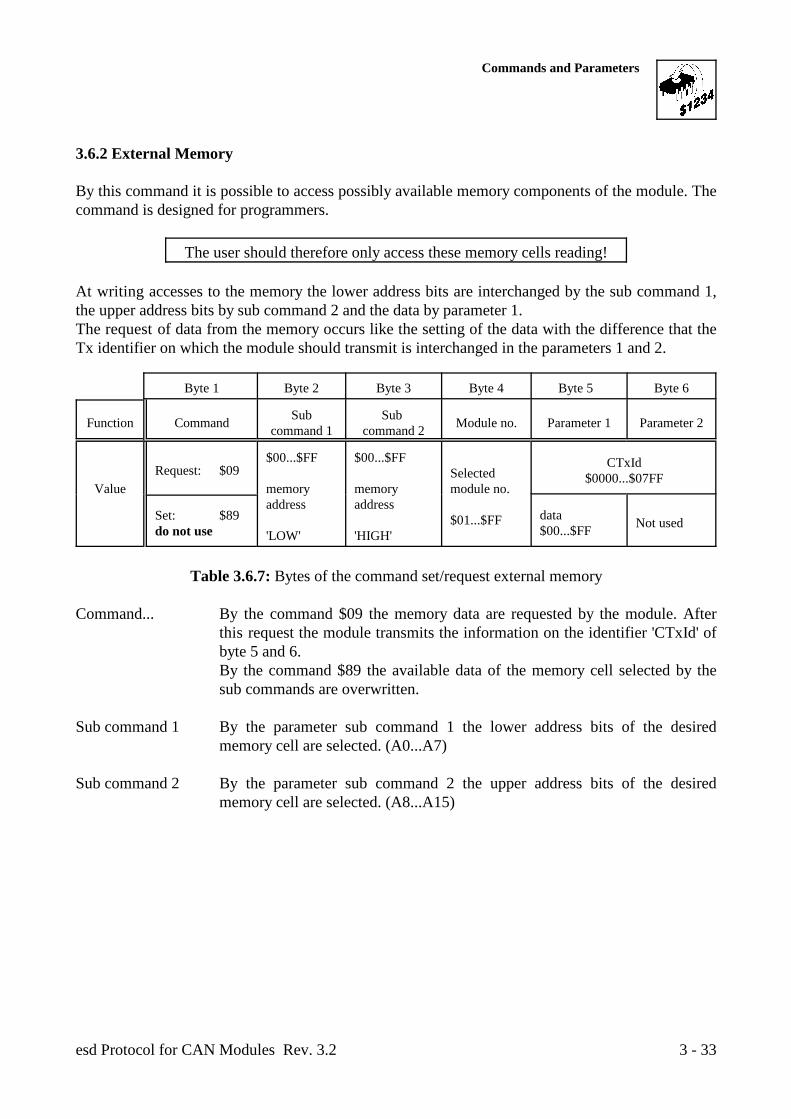
3.6.2 External Memory
By this command it is possible to access possibly available memory components of the module. Thecommand is designed for programmers.
The user should therefore only access these memory cells reading! At writing accesses to the memory the lower address bits are interchanged by the sub command 1,the upper address bits by sub command 2 and the data by parameter 1.The request of data from the memory occurs like the setting of the data with the difference that theTx identifier on which the module should transmit is interchanged in the parameters 1 and 2.
Byte 1 Byte 2 Byte 3 Byte 4 Byte 5 Byte 6
Function Command Module no. Parameter 1 Parameter 2Sub Sub command 1 command 2
Value memory memory module no.Request: $09
$00...$FF $00...$FF
address address
'LOW' 'HIGH'
Selected
$01...$FF
CTxId$0000...$07FF
Set: $89do not use
data$00...$FF Not used
Table 3.6.7: Bytes of the command set/request external memory
Command... By the command $09 the memory data are requested by the module. Afterthis request the module transmits the information on the identifier 'CTxId' ofbyte 5 and 6.By the command $89 the available data of the memory cell selected by thesub commands are overwritten.
Sub command 1 By the parameter sub command 1 the lower address bits of the desiredmemory cell are selected. (A0...A7)
Sub command 2 By the parameter sub command 2 the upper address bits of the desiredmemory cell are selected. (A8...A15)
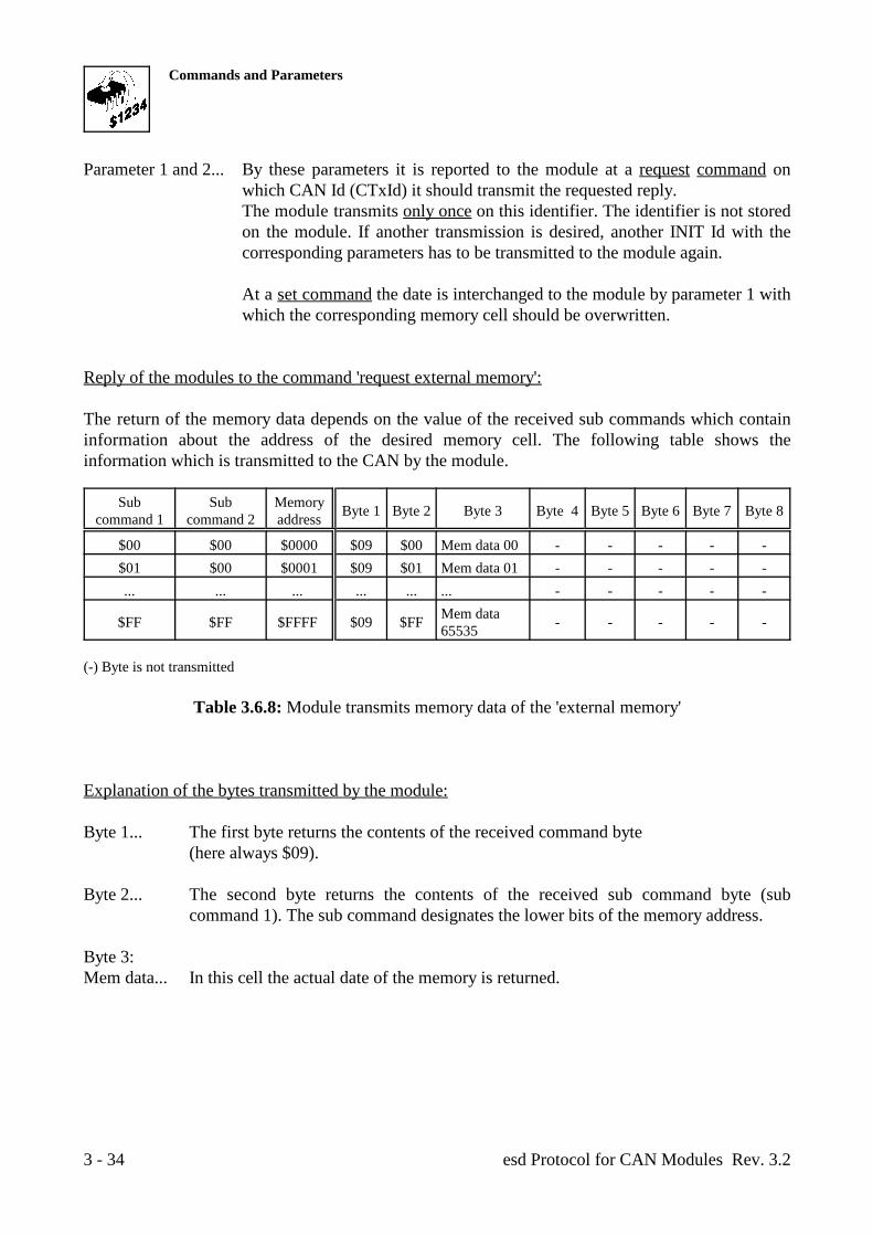
Commands and Parameters
esd Protocol for CAN Modules Rev. 3.23 - 34
Parameter 1 and 2... By these parameters it is reported to the module at a request command onwhich CAN Id (CTxId) it should transmit the requested reply.The module transmits only once on this identifier. The identifier is not storedon the module. If another transmission is desired, another INIT Id with thecorresponding parameters has to be transmitted to the module again.
At a set command the date is interchanged to the module by parameter 1 withwhich the corresponding memory cell should be overwritten.
Reply of the modules to the command 'request external memory':
The return of the memory data depends on the value of the received sub commands which containinformation about the address of the desired memory cell. The following table shows theinformation which is transmitted to the CAN by the module.
Sub Sub Memorycommand 1 command 2 address Byte 1 Byte 2 Byte 3 Byte 4 Byte 5 Byte 6 Byte 7 Byte 8
$00 $00 $0000 $09 $00 Mem data 00 - - - - -$01 $00 $0001 $09 $01 Mem data 01 - - - - -... ... ... ... ... ... - - - - -
$FF $FF $FFFF $09 $FF - - - - -Mem data65535
(-) Byte is not transmitted
Table 3.6.8: Module transmits memory data of the 'external memory'
Explanation of the bytes transmitted by the module:
Byte 1... The first byte returns the contents of the received command byte(here always $09).
Byte 2... The second byte returns the contents of the received sub command byte (subcommand 1). The sub command designates the lower bits of the memory address.
Byte 3:Mem data... In this cell the actual date of the memory is returned.
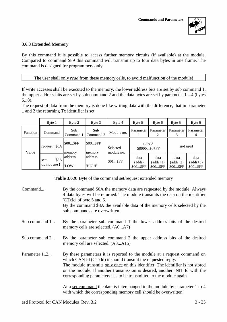
Commands and Parameters
esd Protocol for CAN Modules Rev. 3.2 3 - 35
3.6.3 Extended Memory
By this command it is possible to access further memory circuits (if available) at the module.Compared to command $89 this command will transmit up to four data bytes in one frame. Thecommand is designed for programmers only.
The user shall only read from these memory cells, to avoid malfunction of the module! If write accesses shall be executed to the memory, the lower address bits are set by sub command 1,the upper address bits are set by sub command 2 and the data bytes are set by parameter 1 ...4 (bytes5...8).The request of data from the memory is done like writing data with the difference, that in parameter1 and 2 the returning Tx identifier is set.
Byte 1 Byte 2 Byte 3 Byte 4 Byte 5 Byte 6 Byte 5 Byte 6
Function Command Module no.Sub Sub Parameter Parameter Parameter ParameterCommand 1 Command 2 1 2 3 4
Value memory memory module no.
request: $0A not used$00...$FF $00...$FF
address address
'LOW' 'HIGH'
Selected
$01...$FF
CTxId$0000...$07FF
set: $8Ado not use !
data data data data(addr) (addr+1) (addr+2) (addr+3)
$00...$FF $00...$FF $00...$FF $00...$FF
Table 3.6.9: Byte of the command set/request extended memory
Command... By the command $0A the memory data are requested by the module. Always4 data bytes will be returned. The module transmits the data on the identifier'CTxId' of byte 5 and 6.By the command $8A the available data of the memory cells selected by thesub commands are overwritten.
Sub command 1... By the parameter sub command 1 the lower address bits of the desiredmemory cells are selected. (A0...A7)
Sub command 2... By the parameter sub command 2 the upper address bits of the desiredmemory cell are selected. (A8...A15)
Parameter 1..2... By these parameters it is reported to the module at a request command onwhich CAN Id (CTxId) it should transmit the requested reply.The module transmits only once on this identifier. The identifier is not storedon the module. If another transmission is desired, another INIT Id with thecorresponding parameters has to be transmitted to the module again.
At a set command the date is interchanged to the module by parameter 1 to 4with which the corresponding memory cell should be overwritten.
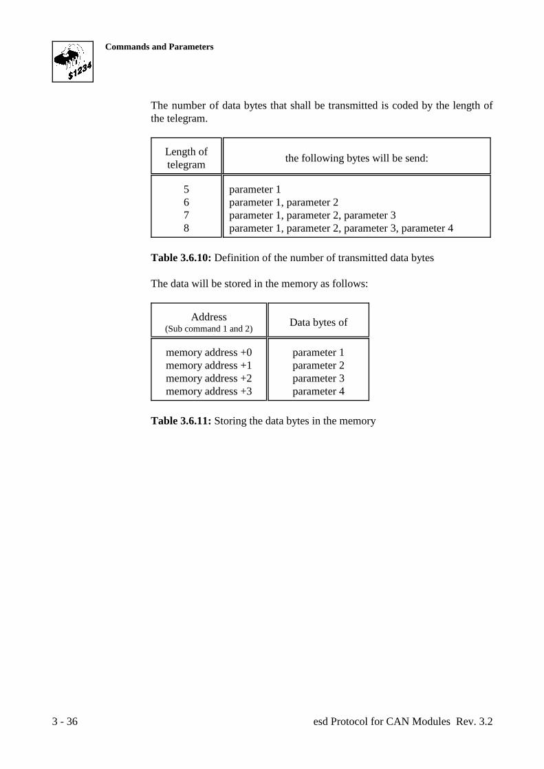
Commands and Parameters
esd Protocol for CAN Modules Rev. 3.23 - 36
The number of data bytes that shall be transmitted is coded by the length ofthe telegram.
Length oftelegram the following bytes will be send:
5 parameter 16 parameter 1, parameter 27 parameter 1, parameter 2, parameter 38 parameter 1, parameter 2, parameter 3, parameter 4
Table 3.6.10: Definition of the number of transmitted data bytes
The data will be stored in the memory as follows:
Address(Sub command 1 and 2)
Data bytes of
memory address +0 parameter 1memory address +1 parameter 2memory address +2 parameter 3memory address +3 parameter 4
Table 3.6.11: Storing the data bytes in the memory
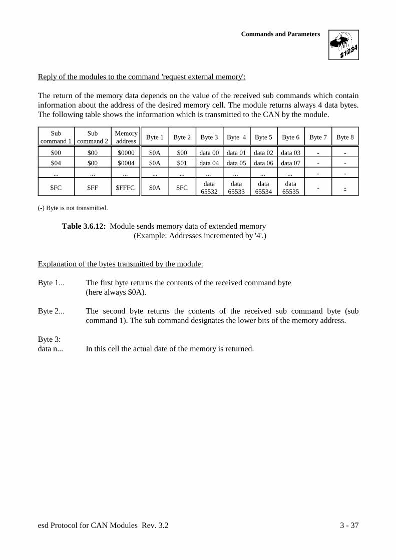
Commands and Parameters
esd Protocol for CAN Modules Rev. 3.2 3 - 37
Reply of the modules to the command 'request external memory':
The return of the memory data depends on the value of the received sub commands which containinformation about the address of the desired memory cell. The module returns always 4 data bytes.The following table shows the information which is transmitted to the CAN by the module.
Sub Sub Memorycommand 1 command 2 address Byte 1 Byte 2 Byte 3 Byte 4 Byte 5 Byte 6 Byte 7 Byte 8
$00 $00 $0000 $0A $00 data 00 data 01 data 02 data 03 - -$04 $00 $0004 $0A $01 data 04 data 05 data 06 data 07 - -... ... ... ... ... ... ... ... ... - -
$FC $FF $FFFC $0A $FC - -data data data data65532 65533 65534 65535
(-) Byte is not transmitted.
Table 3.6.12: Module sends memory data of extended memory(Example: Addresses incremented by '4'.)
Explanation of the bytes transmitted by the module:
Byte 1... The first byte returns the contents of the received command byte(here always $0A).
Byte 2... The second byte returns the contents of the received sub command byte (subcommand 1). The sub command designates the lower bits of the memory address.
Byte 3:data n... In this cell the actual date of the memory is returned.
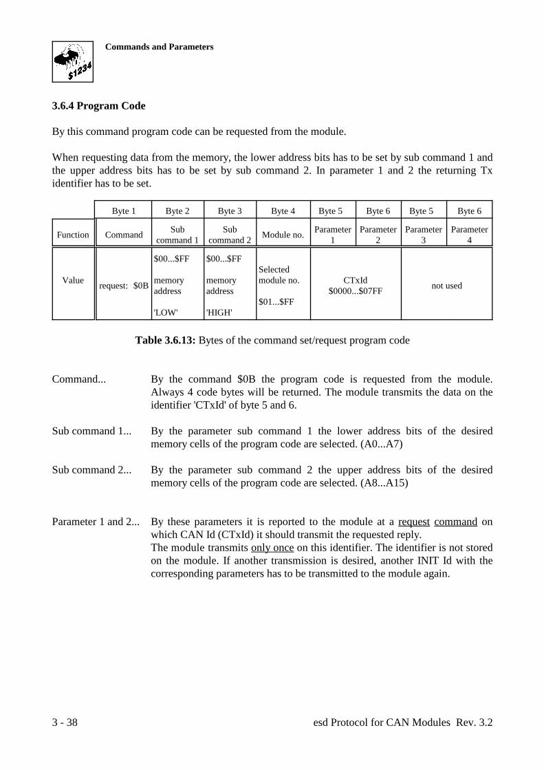
Commands and Parameters
esd Protocol for CAN Modules Rev. 3.23 - 38
3.6.4 Program Code
By this command program code can be requested from the module.
When requesting data from the memory, the lower address bits has to be set by sub command 1 andthe upper address bits has to be set by sub command 2. In parameter 1 and 2 the returning Txidentifier has to be set.
Byte 1 Byte 2 Byte 3 Byte 4 Byte 5 Byte 6 Byte 5 Byte 6
Function Command Module no.Sub Sub Parameter Parameter Parameter Parametercommand 1 command 2 1 2 3 4
Value memory memory module no. CTxIdrequest: $0B not used
$00...$FF $00...$FF
address address $0000...$07FF
'LOW' 'HIGH'
Selected
$01...$FF
Table 3.6.13: Bytes of the command set/request program code
Command... By the command $0B the program code is requested from the module.Always 4 code bytes will be returned. The module transmits the data on theidentifier 'CTxId' of byte 5 and 6.
Sub command 1... By the parameter sub command 1 the lower address bits of the desiredmemory cells of the program code are selected. (A0...A7)
Sub command 2... By the parameter sub command 2 the upper address bits of the desiredmemory cells of the program code are selected. (A8...A15)
Parameter 1 and 2... By these parameters it is reported to the module at a request command onwhich CAN Id (CTxId) it should transmit the requested reply.The module transmits only once on this identifier. The identifier is not storedon the module. If another transmission is desired, another INIT Id with thecorresponding parameters has to be transmitted to the module again.
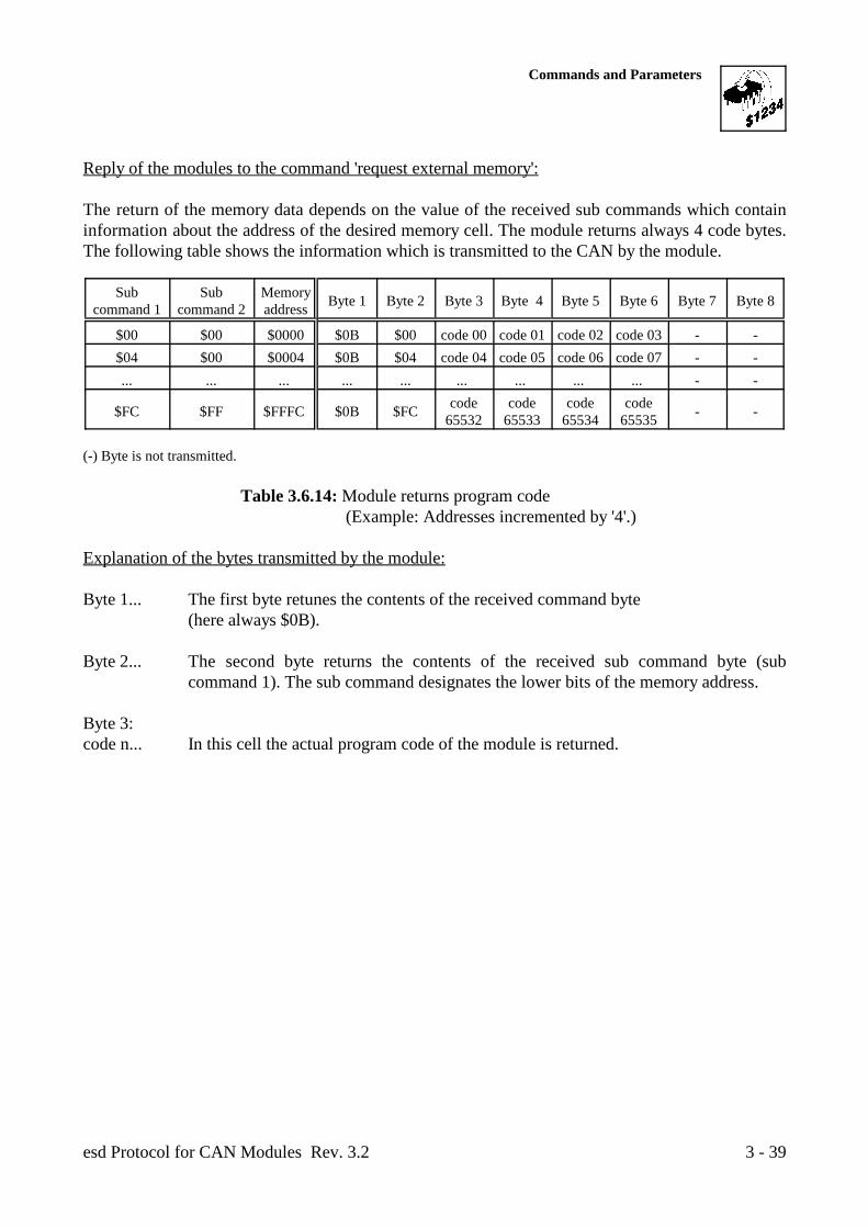
Commands and Parameters
esd Protocol for CAN Modules Rev. 3.2 3 - 39
Reply of the modules to the command 'request external memory':
The return of the memory data depends on the value of the received sub commands which containinformation about the address of the desired memory cell. The module returns always 4 code bytes.The following table shows the information which is transmitted to the CAN by the module.
Sub Sub Memorycommand 1 command 2 address Byte 1 Byte 2 Byte 3 Byte 4 Byte 5 Byte 6 Byte 7 Byte 8
$00 $00 $0000 $0B $00 code 00 code 01 code 02 code 03 - -$04 $00 $0004 $0B $04 code 04 code 05 code 06 code 07 - -... ... ... ... ... ... ... ... ... - -
$FC $FF $FFFC $0B $FC - -code code code code65532 65533 65534 65535
(-) Byte is not transmitted.
Table 3.6.14: Module returns program code(Example: Addresses incremented by '4'.)
Explanation of the bytes transmitted by the module:
Byte 1... The first byte retunes the contents of the received command byte(here always $0B).
Byte 2... The second byte returns the contents of the received sub command byte (subcommand 1). The sub command designates the lower bits of the memory address.
Byte 3:code n... In this cell the actual program code of the module is returned.
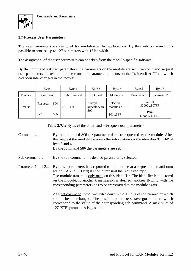
Commands and Parameters
esd Protocol for CAN Modules Rev. 3.23 - 40
3.7 Process User Parameters
The user parameters are designed for module-specific applications. By this sub command it ispossible to process up to 127 parameters with 16 bit width.
The assignment of the user parameters can be taken from the module-specific software.
By the command 'set user parameters' the parameters on the module are set. The command 'requestuser parameters' makes the module return the parameter contents on the Tx identifier CTxId whichhad been interchanged in the request.
Byte 1 Byte 2 Byte 3 Byte 4 Byte 5 Byte 6
Function Command Sub command Not used Module no. Parameter 1 Parameter 2
Value $00...$7F allocate with module no.Request: $06 Always Selected
$00 $01...$FF
CTxId$0000...$07FF
Set: $86 Para$0000...$FFFF
Table 3.7.1: Bytes of the command set/request user parameters
Command... By the command $06 the parameter data are requested by the module. Afterthis request the module transmits the information on the identifier 'CTxId' ofbyte 5 and 6.By the command $86 the parameters are set.
Sub command... By the sub command the desired parameter is selected.
Parameter 1 and 2... By these parameters it is reported to the module at a request command ontowhich CAN Id (CTxId) it should transmit the requested reply.The module transmits only once on this identifier. The identifier is not storedon the module. If another transmission is desired, another INIT Id with thecorresponding parameters has to be transmitted to the module again.
At a set command these two bytes contain the 16 bits of the parameter whichshould be interchanged. The possible parameters have got numbers whichcorrespond to the value of the corresponding sub command. A maximum of127 ($7F) parameters is possible.
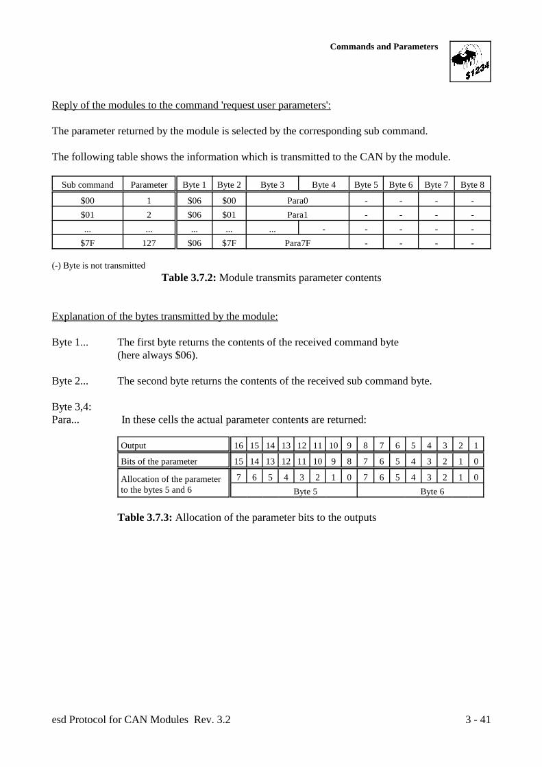
Commands and Parameters
esd Protocol for CAN Modules Rev. 3.2 3 - 41
Reply of the modules to the command 'request user parameters':
The parameter returned by the module is selected by the corresponding sub command.
The following table shows the information which is transmitted to the CAN by the module.
Sub command Parameter Byte 1 Byte 2 Byte 3 Byte 4 Byte 5 Byte 6 Byte 7 Byte 8
$00 1 $06 $00 Para0 - - - -$01 2 $06 $01 Para1 - - - -... ... ... ... ... - - - - -
$7F 127 $06 $7F Para7F - - - -
(-) Byte is not transmittedTable 3.7.2: Module transmits parameter contents
Explanation of the bytes transmitted by the module:
Byte 1... The first byte returns the contents of the received command byte(here always $06).
Byte 2... The second byte returns the contents of the received sub command byte.
Byte 3,4:Para... In these cells the actual parameter contents are returned:
Output 16 15 14 13 12 11 10 9 8 7 6 5 4 3 2 1
Bits of the parameter 15 14 13 12 11 10 9 8 7 6 5 4 3 2 1 0
Allocation of the parameterto the bytes 5 and 6
7 6 5 4 3 2 1 0 7 6 5 4 3 2 1 0 Byte 5 Byte 6
Table 3.7.3: Allocation of the parameter bits to the outputs
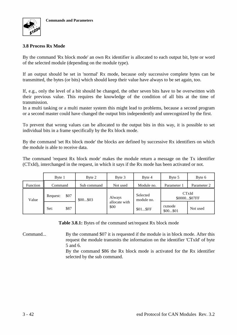
Commands and Parameters
esd Protocol for CAN Modules Rev. 3.23 - 42
3.8 Process Rx Mode
By the command 'Rx block mode' an own Rx identifier is allocated to each output bit, byte or wordof the selected module (depending on the module type).
If an output should be set in 'normal' Rx mode, because only successive complete bytes can betransmitted, the bytes (or bits) which should keep their value have always to be set again, too.
If, e.g., only the level of a bit should be changed, the other seven bits have to be overwritten withtheir previous value. This requires the knowledge of the condition of all bits at the time oftransmission.In a multi tasking or a multi master system this might lead to problems, because a second programor a second master could have changed the output bits independently and unrecognized by the first.
To prevent that wrong values can be allocated to the output bits in this way, it is possible to setindividual bits in a frame specifically by the Rx block mode.
By the command 'set Rx block mode' the blocks are defined by successive Rx identifiers on whichthe module is able to receive data.
The command 'request Rx block mode' makes the module return a message on the Tx identifier(CTxId), interchanged in the request, in which it says if the Rx mode has been activated or not.
Byte 1 Byte 2 Byte 3 Byte 4 Byte 5 Byte 6
Function Command Sub command Not used Module no. Parameter 1 Parameter 2
Value $00...$03 module no.Request: $07 Always
allocate with$00
Selected
$01...$FF
CTxId$0000...$07FF
Set: $87 Not usedrxmode$00...$01
Table 3.8.1: Bytes of the command set/request Rx block mode
Command... By the command $07 it is requested if the module is in block mode. After thisrequest the module transmits the information on the identifier 'CTxId' of byte5 and 6.By the command $86 the Rx block mode is activated for the Rx identifierselected by the sub command.
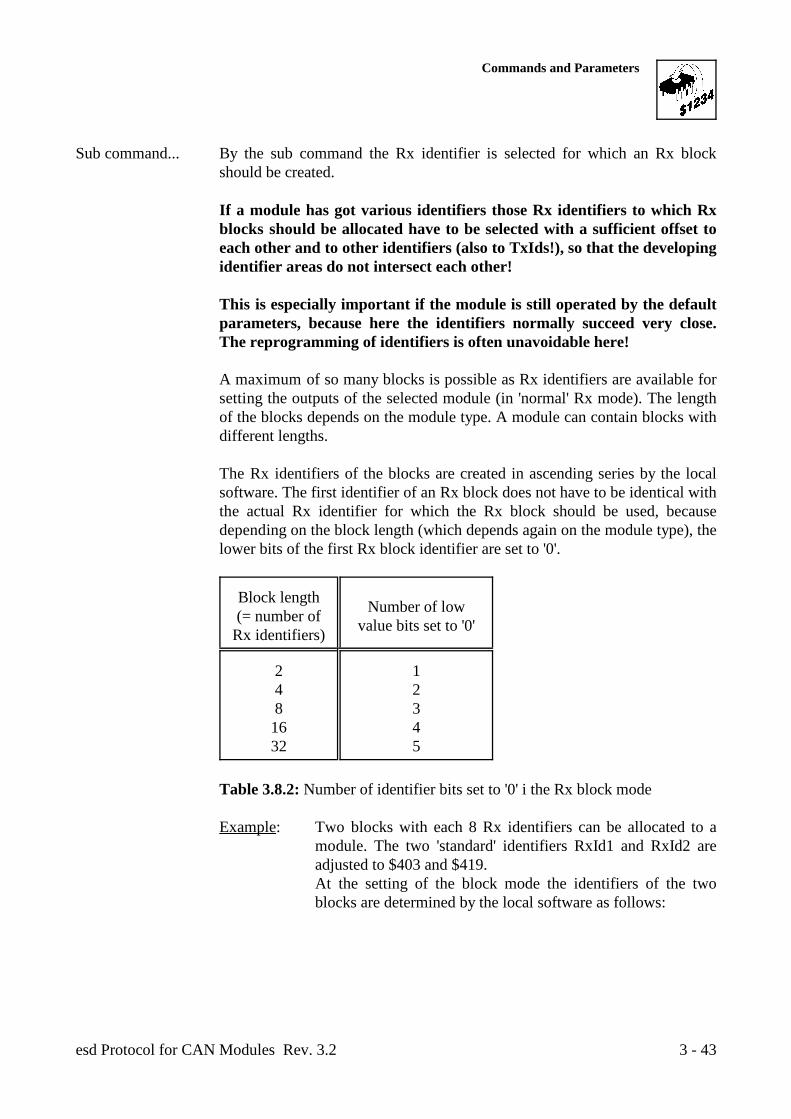
Commands and Parameters
esd Protocol for CAN Modules Rev. 3.2 3 - 43
Sub command... By the sub command the Rx identifier is selected for which an Rx blockshould be created.
If a module has got various identifiers those Rx identifiers to which Rxblocks should be allocated have to be selected with a sufficient offset toeach other and to other identifiers (also to TxIds!), so that the developingidentifier areas do not intersect each other!
This is especially important if the module is still operated by the defaultparameters, because here the identifiers normally succeed very close.The reprogramming of identifiers is often unavoidable here!
A maximum of so many blocks is possible as Rx identifiers are available forsetting the outputs of the selected module (in 'normal' Rx mode). The lengthof the blocks depends on the module type. A module can contain blocks withdifferent lengths.
The Rx identifiers of the blocks are created in ascending series by the localsoftware. The first identifier of an Rx block does not have to be identical withthe actual Rx identifier for which the Rx block should be used, becausedepending on the block length (which depends again on the module type), thelower bits of the first Rx block identifier are set to '0'.
Block length(= number of
Rx identifiers)
Number of lowvalue bits set to '0'
2 14 28 316 432 5
Table 3.8.2: Number of identifier bits set to '0' i the Rx block mode
Example: Two blocks with each 8 Rx identifiers can be allocated to amodule. The two 'standard' identifiers RxId1 and RxId2 areadjusted to $403 and $419.At the setting of the block mode the identifiers of the twoblocks are determined by the local software as follows:
Commands and Parameters
esd Protocol for CAN Modules Rev. 3.23 - 44
Block 1: RxId-B11 = $400RxId-B12 = $401
.... RxId-B18 = $407
Block 2: RxId-B21 = $418RxId-B22 = $419
.... RxId-B28 = $41F
If the block mode has been selected, after an RxId request command the firstRx identifier and the last Rx identifier of the block are returned.
After resetting the Rx block mode the Rx identifier originally entered, forwhich this block stood, is taken over again. Related to the example abovethese would be the Ids $403 or $419.
Parameter 1 and 2... By these two parameters it is reported to the module at a request command towhich CAN Id (CTxId) it should transmit the requested reply.The module transmits only once on this identifier. The identifier is not storedon the module. If another transmission is desired, another INIT Id with thecorresponding parameters has to be transmitted to the module again.
By a set command the Rx block mode is activated or deactivated byparameter 1 (rxmode).
Parameter(rxmode) Function
$00 Normal Rx mode
$01 Rx block mode activated
$02... No function
$FF
Table 3.8.3: Setting the block mode by parameter 1
Commands and Parameters
esd Protocol for CAN Modules Rev. 3.2 3 - 45
Reply of the modules to the command 'request Rx block mode':
The parameter returned by the module is selected by the corresponding sub command.
The following table shows the information which the module transmits to the CAN.
Sub Rx block forcommand RxId Byte 1 Byte 2 Byte 3 Byte 4 Byte 5 Byte 6 Byte 7 Byte 8
$00 RxId 1 $07 $00 rxmode1 - - - - -$01 RxId 2 $07 $01 rxmode2 - - - - -$02 RxId 3 $07 $02 rxmode3 - - - - -$03 RxId 4 $07 $03 rxmode4 - - - - -
(-) Byte is not transmittedTable 3.8.4: Module transmits Rx block mode status
Explanation of the bytes transmitted by the module:
Byte 1... The first byte returns the contents of the received command byte(here always $07).
Byte 2... The second byte returns the contents of the received sub command.
Byte 3:rxmode... In these cells the module returns if the block mode has been selected for the
corresponding Rx identifier and which length the block has got. The parameter cantake over following values:
rxmode(Byte 3) Block length
$00 Block mode switched off
$02 Block length = 2 RxIds$04 " = 4 RxIds$08 " = 8 RxIds$0F " = 16 RxIds$20 " = 32 RxIds
Table 3.8.5: Block length in parameter 'rxmode'
Commands and Parameters
esd Protocol for CAN Modules Rev. 3.23 - 46
3.9 Allocation of Pin Names
The allocation of names to the individual I/O pins or channels has been developed as a user specificfunction which should give the CAN master another opportunity to identify the modules. Thereading of the pin names of a module and their check by the previously entered 'set names' shouldsecure that the module is addressed correctly.
This function is only implemented if the module has got an EEPROM which has got a memorycapacity of more than 128 bytes, because the pin names have been filed in the EEPROM.
The user can find out if the function is implemented by inquiring the fourth bit ('EEPROM size') ofthe CAN-status byte 'cstat'. The description of the inquiry can be found in the previous chapter'system parameters'.
The CAN master can allocate a name in ASCII code of up to 24 bytes long to each I/O pin of amodule. The pins and the bytes of the pin names are selected by the sub commands.
The return of the Pin names also occurs byte by byte.
Byte 1 Byte 2 Byte 3 Byte 4 Byte 5 Byte 6
Function Command Sub command 1 Sub command 2 Parameter 1 Parameter 2Moduleno.
Value $00...$FF interchanged module no.
Request: $08Pin number
(module bytedependent) $00...$17 $01...$FF
Number of the SelectedCTxId
$0000...$07FF
Set: $88 $00...$FF Not usedByte name
(ASCII)
Table 3.9.1: Bytes of the command set/request pin name
Command... By the command $88 the individual bytes of the pin names are requested. Themodule transmits the information of this inquiry on the identifier 'CTxId' ofbyte 5 and 6.By the command $89 the pin names are set.
Sub command 1 By the sub command the pin is selected whose name should be processed.The number of pins depends on the module type (e.g.: CDO16 - 16 pins).
The new pin name is only saved in the EEPROM by the firmware if the 24th
byte (byte no. 23) of the name had been processed! Therefore it is onlypossible to process the bytes of one pin until the last byte (no.23) isprocessed!
Commands and Parameters
esd Protocol for CAN Modules Rev. 3.2 3 - 47
Sub command 2 In byte 3 of the INIT Id the number of the byte is entered which should bechanged in the pin name. A pin name is 24 bytes long (byte 0..byte 23).
The transmitted bytes of a pin name are only filed in the EEPROM, if thebyte no. 23 of a pin name had been transmitted.
The bytes are not filed like other parameters by the command 'saveparameters' in the EEPROM, but only by setting the byte no. 23!
Parameter 1 and 2... By these parameters it is reported to the module at a request command towhich CAN Id (CTxId) it should transmit the requested reply.The module transmits only once on this identifier. The identifier is not storedby the module. If another transmission is desired, another INIT Id with thecorresponding parameters has to be transmitted to the module.
At a set command parameter 1 contains the 8 bits of the byte of a pin namewhich should be interchanged.
Commands and Parameters
esd Protocol for CAN Modules Rev. 3.23 - 48
Reply of the modules to the command 'request pin name':
The parameter returned by the module is selected by the corresponding sub commands.
The following table shows the information which is transmitted to the CAN by the module. Thereply does not contain information about the requested byte number (sub command 2).
Sub command 1 Pin/Channel Byte 1 Byte 2 Byte 3 Byte 4 Byte 5 Byte 6 Byte 7 Byte 8
$00 Pin 1 $08 $00 byte name - - - - -$01 Pin 2 $08 $01 byte name - - - - -... ... $08 ... ... - - - - -
$FF Pin 256 $08 $FF byte name - - - - -
(-) Byte is not transmittedTable 3.9.2: Module transmits Rx block mode status
Explanation of the bytes transmitted by the module:
Byte 1... The first byte returns the contents of the received command byte(here always $08).
Byte 2... The second byte returns the contents of the received sub command byte (subcommand 1 =< pin number).
Byte 3... In byte 3 the contents of the byte which has been selected in the request is returned.
Commands and Parameters
esd Protocol for CAN Modules Rev. 3.2 3 - 49
3.10 Service Request
By this command it is possible to inquire the error condition of the esd-CAN modules. It is possibleto make various or individual modules return a transmission if they show the error status 'error onCAN' or the status bit 'new on bus' is active. The message consists of a Tx frame which has got no data.
The parameters of the modules remain unchanged when this command is requested.
The command can be used to find out which modules operate faultless on the bus and whichmodules have got transmission problems.
Byte 1 Byte 2 Byte 3 Byte 4 Byte 5 Byte 6
Function Command Sub command 1 Sub command 2 Not used Parameter 1 Parameter 2
Value $7F allocate withModule no_LOW Module no_HIGH CTxId$00...$FF $00...$FF $0000...$07FF
Always
$00
Table 3.10.1: Bytes of the command service request
Explanation of the bytes transmitted to the module:
Command... This command has got the value $7F.
Sub command1, Sub command2... By the sub commands the modules are selected which should be checked.
The modules are addressed by their module numbers. To select an area with various modules, in sub command 1 the lowest and insub command 2 the highest module no. of the desired area has to be entered.The limit values are included. If only one module should transmit a statusmessage, the same module no. has to be entered for both sub commands.
Byte 4... In contrast to most of the other commands, here byte 4 and not byte 3 shouldbe allocated with '$00'.
Parameter 1,Parameter 2... In byte 5 and byte 6 the Tx identifier is interchanged on which the module
should transmit a reply.
Commands and Parameters
esd Protocol for CAN Modules Rev. 3.23 - 50
Reply of the module to the command 'service request':
If a module receives this command, and if a short term CAN error existed (bit 'error on CAN' = 1)or/and if the bit 'new on bus' is active, the module transmits a message with the length 0 on thereceived Tx identifier. No bytes are transmitted.
TxId Byte 1 Byte 2 Byte 3 Byte 4 Byte 5 Byte 6 Byte 7 Byte 8
CTxId - - - - - - - -
(-) Byte is not transmittedTable 3.10.2: Reply by CTxId
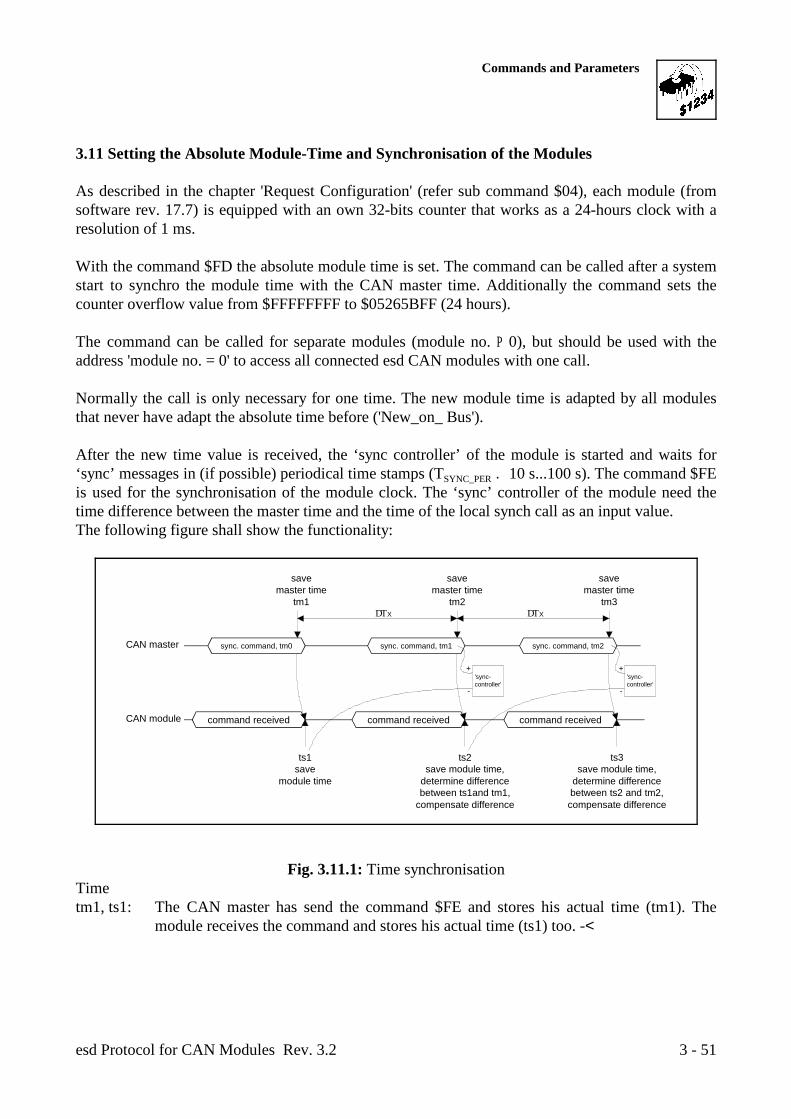
ts2save module time,
determine differencebetween ts1and tm1,
compensate difference
CAN master
CAN module
savemaster time
tm1
ts1save
module time
DTX
command received
savemaster time
tm2
savemaster time
tm3DTX
command received
sync. command, tm0 sync. command, tm1 sync. command, tm2
'sync-controller'
+
-
+
-
command received
'sync-controller'
ts3save module time,
determine differencebetween ts2 and tm2,compensate difference
Commands and Parameters
esd Protocol for CAN Modules Rev. 3.2 3 - 51
3.11 Setting the Absolute Module-Time and Synchronisation of the Modules
As described in the chapter 'Request Configuration' (refer sub command $04), each module (fromsoftware rev. 17.7) is equipped with an own 32-bits counter that works as a 24-hours clock with aresolution of 1 ms.
With the command $FD the absolute module time is set. The command can be called after a systemstart to synchro the module time with the CAN master time. Additionally the command sets thecounter overflow value from $FFFFFFFF to $05265BFF (24 hours).
The command can be called for separate modules (module no. P 0), but should be used with theaddress 'module no. = 0' to access all connected esd CAN modules with one call.
Normally the call is only necessary for one time. The new module time is adapted by all modulesthat never have adapt the absolute time before ('New_on_ Bus').
After the new time value is received, the ‘sync controller’ of the module is started and waits for‘sync’ messages in (if possible) periodical time stamps (T . 10 s...100 s). The command $FESYNC_PER
is used for the synchronisation of the module clock. The ‘sync’ controller of the module need thetime difference between the master time and the time of the local synch call as an input value.The following figure shall show the functionality:
Fig. 3.11.1: Time synchronisationTimetm1, ts1: The CAN master has send the command $FE and stores his actual time (tm1). The
module receives the command and stores his actual time (ts1) too. -<
Commands and Parameters
esd Protocol for CAN Modules Rev. 3.23 - 52
tm2, ts2: When transmitting the next synchronisation command the master sends tm1 and storesthe actual time as tm2. The slave receives tm1 and determines his difference value fromts1 and tm1.
tm3, ts3: The sequence of tm2/ts2 is repeated with every command call.
The transfer of the synchronisation command should be executed in intervals between 10 s and2 min. Is the difference between nominal value and real value (Îtime) high, a transfer between5...10 s is useful. The time difference Îtime can be requested by the command 'RequestConfiguration’.
The accuracy of the synchronisation depends on the time the CAN master needs for storing hisactual master time after the synchro command is send. The shorter this time is, the more precise isthe synchronisation. Additionally it is important that the master time is always stored after aconstant delay time after the transfer of the command. The higher the ’jitter', the higher is the errorof the synchronisation.
Byte 1 Byte 2 Byte 3 Byte 4 Byte 5 Byte 6 Byte 7 Byte 8
Function Command Module no. Parameter 2 Parameter 4Sub not Parameter Parametercommand used 1 3
Value $00 $00$FD- absolute_time absolute_timeSelected
module no.$00,$01...$FF$FE- sync_time sync_time_master
Table 3.11.1: Bytes of the commands 'setting the absolute module time' and 'synchronisation ofthe modules'
Explanation of the bytes transmitted to the module:
Command... These commands have got the values $7F (setting of the absolute moduletime) and $FE (synchronisation of the module time). With these commandsno parameters can be requested. But the actual module time can be requestedby the command ‘Request Configuration'.
Sub command ... Has always be set to '0'.
Parameter 1 toParameter 4 ... With the command $FD in byte 5 to byte 8 the absolute module time is set.
(absolute_time...).Value range: 0 ... 86 400 000 ms (24 h)
(0 ... $ 05 26 5B FF)
With the command $FE the synchronisation time of the master (sync_time_master) is set (refer to description at the previous page).
Commands and Parameters
esd Protocol for CAN Modules Rev. 3.2 3 - 53
3.12 Supervisor Commands
In contrast to the other commands, supervisor commands are able to address individual or allmodules in the CAN net.By the module no. $00 all modules are selected. Therefore it is not recommendable to adjust themodule no. $00 on a module.The supervisor commands are not able to request parameters from the module.
The command RESET has got the same consequences as a 'power-on RESET'. It resets allparameters which are not stored in the EEPROM. After the RESET the parameters filed in theEEPROM are active, or, if the EEPROM data are defective or the EEPROM is not available, thedefault parameters.
If individual or all modules should be reset in a way that they operate with the default parametersafter the RESET, this can be achieved by the command default RESET.
During a local RESET the message outputs are activated.
The command Supervisor Watchdog can be called by the Supervisor, to activate the watchdogfunctionality (precondition is that the watchdog time and the life time factor are greater than ‘0’).After the first activation the command has to be repeated within the time 'WDtime xWDLifeTimeFactor' otherwise a local RESET is generated at the module (refer to chapter 'SystemParameter').
The command suspend module causes one or all modules on the CAN to 'freeze' the actualcondition of their outputs (if available) and not transmit any messages (Tx transfers) to the CAN(exception: configuration reply).
Parameters and commands are received and filed by the module, but not evaluated: It is possibletherefore, e.g., to set output data on the module without changing the output conditions at once.
If the module is activated again by the command 'continue', possibly available outputs are setimmediately according to the last received data and the module operates with the last receivedparameters.
Commands and Parameters
esd Protocol for CAN Modules Rev. 3.23 - 54
Byte 1 Byte 2 Byte 3 Byte 4 Byte 5 Byte 6
Function Command Sub command Not used Parameter 1 Parameter 2selectedmodule no.
Value $FF allocate
$00 Trigger RESET $AAAA - RESET
Always selected
with $00 $01..$FF
$00 Allmodules
One moduleselected
$01 Reserved -
$02 Supervisor Watchdog -
$03 Default RESET $AAAA - Default RESET
$04 Suspend/continue $5A5A - Suspend module $A5A5 - Continue
$05 -Reset CAN-error bit
Table 3.12.1: Bytes of the supervisor commands
Explanation of the bytes transmitted to the module:
Command... The supervisor commands all have got the value $FF.
Sub command... The sub command selects the corresponding supervisor command:
Subcommand Function
$00 Reset module$01 Reserved$02 Supervisor Watchdog$03 Reset module and activate the default parameters$04 Suspend module$05 Reset CAN error bit
Table 3.12.2: Selection of the supervisor commands by the sub command
Commands and Parameters
esd Protocol for CAN Modules Rev. 3.2 3 - 55
Module no. ... Here the desired actual module no. is entered. The setting of individualmodules occurs by the module no. $01 to $FF.
At this command all esd modules connected to this CAN net are accessed atthe same time by the module no. $00!
Parameter 1,.. Depending on the sub command here are parameters interchanged, which arespecific for the function:
The commands RESET, default RESET, suspend/continue modules andresetting the CAN error bits are only carried out, if exactly the specifiedparameters are interchanged.

esd Protocol for CAN Modules Rev. 3.23 - 56
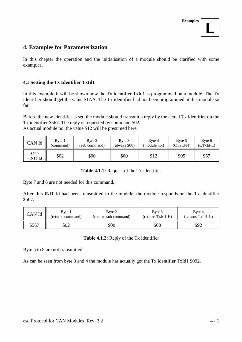
LExamples
esd Protocol for CAN Modules Rev. 3.2 4 - 1
4. Examples for Parameterization
In this chapter the operation and the initialisation of a module should be clarified with someexamples.
4.1 Setting the Tx Identifier TxId1
In this example it will be shown how the Tx identifier TxId1 is programmed on a module. The Txidentifier should get the value $1AA. The Tx identifier had not been programmed at this module sofar.
Before the new identifier is set, the module should transmit a reply by the actual Tx identifier on theTx identifier $567. The reply is requested by command $02.As actual module no. the value $12 will be presumed here.
CAN Id Byte 1 Byte 2 Byte 3 Byte 4 Byte 5 Byte 6(command) (sub command) (always $00) (module no.) (CTxId-H) (CTxId-L)
$700=INIT Id $02 $00 $00 $12 $05 $67
Table 4.1.1: Request of the Tx identifier
Byte 7 and 8 are not needed for this command.
After this INIT Id had been transmitted to the module, the module responds on the Tx identifier$567:
CAN Id Byte 1 Byte 2 Byte 3 Byte 4(returns command) (returns sub command) (returns TxId1-H) (returns TxId1-L)
$567 $02 $00 $00 $92
Table 4.1.2: Reply of the Tx identifier
Byte 5 to 8 are not transmitted.
As can be seen from byte 3 and 4 the module has actually got the Tx identifier TxId1 $092.
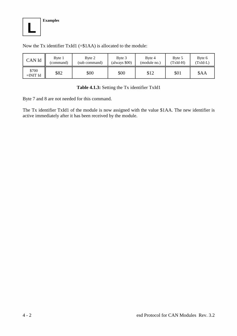
LExamples
esd Protocol for CAN Modules Rev. 3.24 - 2
Now the Tx identifier TxId1 (=$1AA) is allocated to the module:
CAN Id Byte 1 Byte 2 Byte 3 Byte 4 Byte 5 Byte 6(command) (sub command) (always $00) (module no.) (TxId-H) (TxId-L)
$700=INIT Id $82 $00 $00 $12 $01 $AA
Table 4.1.3: Setting the Tx identifier TxId1
Byte 7 and 8 are not needed for this command.
The Tx identifier TxId1 of the module is now assigned with the value $1AA. The new identifier isactive immediately after it has been received by the module.
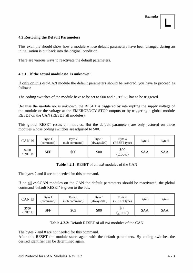
LExamples
esd Protocol for CAN Modules Rev. 3.2 4 - 3
4.2 Restoring the Default Parameters
This example should show how a module whose default parameters have been changed during aninitialisation is put back into the original condition.
There are various ways to reactivate the default parameters.
4.2.1 ...if the actual module no. is unknown:
If only on this esd-CAN module the default parameters should be restored, you have to proceed asfollows:
The coding switches of the module have to be set to $00 and a RESET has to be triggered.
Because the module no. is unknown, the RESET is triggered by interrupting the supply voltage ofthe module or the voltage at the EMERGENCY-STOP outputs or by triggering a global moduleRESET on the CAN (RESET all modules).
This global RESET resets all modules. But the default parameters are only restored on thosemodules whose coding switches are adjusted to $00.
CAN Id Byte 1 Byte 2 Byte 3 Byte 4(command) (sub command) (always $00) (RESET type) Byte 5 Byte 6
$700=INIT Id $FF $00 $00 $AA $AA$00
(global)
Table 4.2.1: RESET of all esd modules of the CAN
The bytes 7 and 8 are not needed for this command.
If on all esd-CAN modules on the CAN the default parameters should be reactivated, the globalcommand 'default RESET' is given to the bus:
CAN Id Byte 1 Byte 2 Byte 3 Byte 4(command) (sub command) (always $00) (RESET type) Byte 5 Byte 6
$700=INIT Id $FF $03 $00 $AA $AA$00
(global)
Table 4.2.2: Default RESET of all esd modules of the CAN
The bytes 7 and 8 are not needed for this command.After this RESET the module starts again with the default parameters. By coding switches thedesired identifier can be determined again.
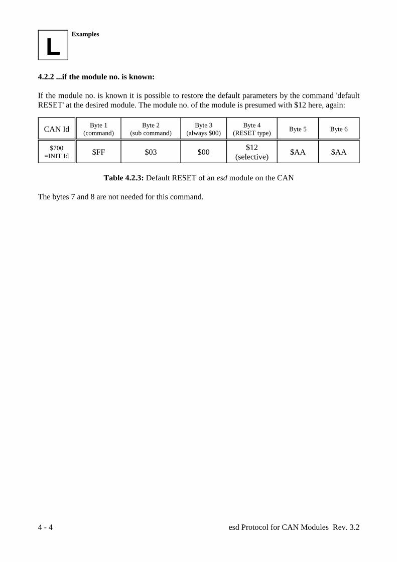
LExamples
esd Protocol for CAN Modules Rev. 3.24 - 4
4.2.2 ...if the module no. is known:
If the module no. is known it is possible to restore the default parameters by the command 'defaultRESET' at the desired module. The module no. of the module is presumed with $12 here, again:
CAN Id Byte 1 Byte 2 Byte 3 Byte 4(command) (sub command) (always $00) (RESET type) Byte 5 Byte 6
$700=INIT Id $FF $03 $00 $AA $AA$12
(selective)
Table 4.2.3: Default RESET of an esd module on the CAN
The bytes 7 and 8 are not needed for this command.